EP2940286A1 - Kraftstoffeinspritzventilfilter - Google Patents
Kraftstoffeinspritzventilfilter Download PDFInfo
- Publication number
- EP2940286A1 EP2940286A1 EP14166767.5A EP14166767A EP2940286A1 EP 2940286 A1 EP2940286 A1 EP 2940286A1 EP 14166767 A EP14166767 A EP 14166767A EP 2940286 A1 EP2940286 A1 EP 2940286A1
- Authority
- EP
- European Patent Office
- Prior art keywords
- filter
- fuel
- control valve
- injector
- flow
- Prior art date
- Legal status (The legal status is an assumption and is not a legal conclusion. Google has not performed a legal analysis and makes no representation as to the accuracy of the status listed.)
- Withdrawn
Links
Images


Classifications
-
- F—MECHANICAL ENGINEERING; LIGHTING; HEATING; WEAPONS; BLASTING
- F02—COMBUSTION ENGINES; HOT-GAS OR COMBUSTION-PRODUCT ENGINE PLANTS
- F02M—SUPPLYING COMBUSTION ENGINES IN GENERAL WITH COMBUSTIBLE MIXTURES OR CONSTITUENTS THEREOF
- F02M61/00—Fuel-injectors not provided for in groups F02M39/00 - F02M57/00 or F02M67/00
- F02M61/16—Details not provided for in, or of interest apart from, the apparatus of groups F02M61/02 - F02M61/14
- F02M61/165—Filtering elements specially adapted in fuel inlets to injector
-
- B—PERFORMING OPERATIONS; TRANSPORTING
- B01—PHYSICAL OR CHEMICAL PROCESSES OR APPARATUS IN GENERAL
- B01D—SEPARATION
- B01D29/00—Filters with filtering elements stationary during filtration, e.g. pressure or suction filters, not covered by groups B01D24/00 - B01D27/00; Filtering elements therefor
- B01D29/11—Filters with filtering elements stationary during filtration, e.g. pressure or suction filters, not covered by groups B01D24/00 - B01D27/00; Filtering elements therefor with bag, cage, hose, tube, sleeve or like filtering elements
- B01D29/114—Filters with filtering elements stationary during filtration, e.g. pressure or suction filters, not covered by groups B01D24/00 - B01D27/00; Filtering elements therefor with bag, cage, hose, tube, sleeve or like filtering elements arranged for inward flow filtration
-
- B—PERFORMING OPERATIONS; TRANSPORTING
- B01—PHYSICAL OR CHEMICAL PROCESSES OR APPARATUS IN GENERAL
- B01D—SEPARATION
- B01D35/00—Filtering devices having features not specifically covered by groups B01D24/00 - B01D33/00, or for applications not specifically covered by groups B01D24/00 - B01D33/00; Auxiliary devices for filtration; Filter housing constructions
- B01D35/005—Filters specially adapted for use in internal-combustion engine lubrication or fuel systems
-
- B—PERFORMING OPERATIONS; TRANSPORTING
- B05—SPRAYING OR ATOMISING IN GENERAL; APPLYING FLUENT MATERIALS TO SURFACES, IN GENERAL
- B05B—SPRAYING APPARATUS; ATOMISING APPARATUS; NOZZLES
- B05B1/00—Nozzles, spray heads or other outlets, with or without auxiliary devices such as valves, heating means
- B05B1/30—Nozzles, spray heads or other outlets, with or without auxiliary devices such as valves, heating means designed to control volume of flow, e.g. with adjustable passages
- B05B1/3013—Lift valves
-
- F—MECHANICAL ENGINEERING; LIGHTING; HEATING; WEAPONS; BLASTING
- F02—COMBUSTION ENGINES; HOT-GAS OR COMBUSTION-PRODUCT ENGINE PLANTS
- F02M—SUPPLYING COMBUSTION ENGINES IN GENERAL WITH COMBUSTIBLE MIXTURES OR CONSTITUENTS THEREOF
- F02M47/00—Fuel-injection apparatus operated cyclically with fuel-injection valves actuated by fluid pressure
- F02M47/02—Fuel-injection apparatus operated cyclically with fuel-injection valves actuated by fluid pressure of accumulator-injector type, i.e. having fuel pressure of accumulator tending to open, and fuel pressure in other chamber tending to close, injection valves and having means for periodically releasing that closing pressure
- F02M47/027—Electrically actuated valves draining the chamber to release the closing pressure
-
- F—MECHANICAL ENGINEERING; LIGHTING; HEATING; WEAPONS; BLASTING
- F02—COMBUSTION ENGINES; HOT-GAS OR COMBUSTION-PRODUCT ENGINE PLANTS
- F02M—SUPPLYING COMBUSTION ENGINES IN GENERAL WITH COMBUSTIBLE MIXTURES OR CONSTITUENTS THEREOF
- F02M2200/00—Details of fuel-injection apparatus, not otherwise provided for
- F02M2200/27—Fuel-injection apparatus with filters
Definitions
- the present invention relates to fuel injector for delivering fuel such as diesel to a combustion space of an internal combustion engine, and more particularly to a filter for a secondary fuel flow through a nozzle control valve of a fuel injector.
- Fuel contaminant particles which are of a smaller size than the lift of the nozzle control valve are flushed away as soon as the valve seat is opened.
- particles of a similar size to the control valve lift can become trapped at the entrance to the control valve seat and remain for a significant number of actuations, before eventually eroding a path through the control valve seat.
- contaminant particles of a dimension similar to the control valve lift which could typically be 10 to 20 microns, are most likely to cause damage to the control valve seat, leading to valve seat leakage and inefficiency of the injector.
- Control valves for common rail injectors are pressurized continuously, and it has proved necessary in prior art embodiments to apply a hard coating on the valve seat, thereby to improve tolerance to fuel contamination.
- common rail injectors are being used at increasingly high pressures, and are increasingly compact and efficient. This new generation of common rail injectors have an increasingly smaller margin in pump capacity to allow for valve seat leakage. Furthermore, the quality of fuel used in the next generation of common rail injectors cannot be ensured across a global market.
- Filters which are currently located on the main fuel inlet to a common rail injector, thereby to filter the primary flow of fuel into the injector comprise relatively large edge or mesh filters.
- the mesh size or clearance of such filters is too large to effectively filter the smaller particles which are most likely to cause damage to the control valve seat, i.e. particles which are of a similar size to the control valve lift. Reducing the mesh size or clearance of such filters is not possible as this would result in excessive pressure drop across the filter, or require a very large filter to maintain the pressure drop within a tolerable level.
- a fuel injector for use in delivering fuel in an internal combustion engine, the fuel injector comprising a housing, an inlet aperture, a control flow aperture leading to a nozzle control valve having a known lift value, a needle piston, and a nozzle cavity provided with at least one nozzle outlet opening; wherein a primary flow of fuel enters the injector through the inlet aperture, and wherein part of the primary flow forms a secondary flow of fuel which enters the control valve through the control flow aperture, and wherein the nozzle control valve controls movement of the needle piston, thereby controlling flow of fuel out of the nozzle cavity through the at least one nozzle outlet opening; characterised by a filter located such that only the secondary flow of fuel passes through the filter, the filter comprising at least one filter orifice, wherein at least one dimension of the at least one filter orifice is less than the nozzle control valve lift value.
- any contaminant particles entering the injector in the primary flow of fuel which have a dimension similar to the lift of the control valve, cannot pass through the filter into the secondary, or control flow or fuel, and therefore such particles cannot cause wear or other damage to the nozzle control valve seat.
- the present invention reduces the risk of control valve seat leakage by preventing fuel contaminant particles of a similar size to the control valve lift reaching the nozzle control valve seat.
- the present invention allows for a significantly smaller and finer filter to be used than in prior art embodiments, as the volume of fuel being filtered is significantly reduced in comparison to filtering of the primary flow of fuel injected into the cylinder.
- the smaller size of filter enabled by the present invention is also possible because a greater pressure drop across the filter can be sustained, without affecting the efficiency of the injection and/or combustion.
- the filter is located within the main fuel flow path between the inlet aperture and the nozzle cavity, such that the primary flow of fuel is directed past the upstream surface of the filter, thereby ensuring that any contaminant particles which are too large to pass through the filter and which have therefore collected on the upstream surface of the filter, are flushed away by swirl caused in the primary flow, and subsequently ejected out of the injector through the nozzle outlet openings, which are significantly larger that the contaminant particles.
- the at least one dimension of the at least one filter orifice may be between a half and a quarter of the nozzle control valve lift value.
- the filter of the present invention may comprise a plurality of holes or other perforations.
- the at least one dimension of the filter orifices which is less than the value of the nozzle control seat lift is the maximum diameter of the holes or other perforations.
- the at least one filter orifice may comprise a plurality of slots.
- the at least one dimension of the filter orifice which is less than the size of the nozzle control valve lift is the width of the slots.
- the filter may comprise a tube and wherein the plurality of holes, or plurality of slots, are provided on a surface of the tube.
- the filter may conveniently be mounted in a part of the injector housing.
- the filter orifices could alternatively be machined into a surface of an alternative further component, or the surface of existing injector part or component.
- the filter may alternatively be formed by a small clearance between two components, i.e. similar to an edge filter.
- the at least one dimension of the filter orifice which is less than the value of the nozzle control valve lift is the clearance between the two components.
- the filter may be formed by a mesh filter, comprising a plurality of mesh orifices.
- the at least one dimension of the filter orifice which is less than the value of the nozzle control valve lift is a minimum dimension of each mesh orifice.
- the present invention comprises a fuel injector 2 suitable for delivering fuel to an engine cylinder or other combustion space of an internal combustion engine.
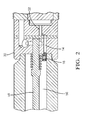
- the fuel injector 2 comprises an injector housing and an injector inlet aperture 12 (shown in Figures 2 and 3 ) through which a main, or primary fuel flow enters the injector 2, in direction A ( Figure 3 ).
- a nozzle cavity 56 is supplied with fuel from the primary flow.
- the fuel injector 2 further comprises a nozzle control valve (located generally in region 52) including a valve seat (not shown in figures), the nozzle control valve having a known value of lift.
- a nozzle control valve located generally in region 52
- the nozzle control valve having a known value of lift.
- Part of the primary fuel flow typically 10%
- forms a secondary, or control fuel flow which is directed through a control flow aperture 14, in direction B (shown in Figure 3 ) towards the control valve.
- Fuel pressure within a valve control chamber controls the motion of a needle piston 58, thereby controlling the flow of fuel from the nozzle cavity 56, through nozzle outlet openings (not shown in the figures).
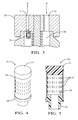
- the injector 2 further comprises a filter 16 which, in the embodiment illustrated in the figures and most clearly illustrated in Figures 4 to 8 , comprises a midsection 26 comprising an elongate tube of circular cross-section, a closed end cap 22 and a base section 24.
- the midsection 26 and the base section 24 are provided with through bores.
- the midsection 26 is provided with a plurality of filter orifices, which in the illustrated embodiment comprise elongate slots 20.
- the slots 20 have a width dimension W and a length dimension L (both shown in Figure 7 ), the width dimension W being less than the known value of lift of the nozzle control valve.
- the base 24 of the filter 16 is mounted in a section of the piston guide 30, adjacent the control flow aperture 14, such that fuel flowing through the filter 16 subsequently flows through the control flow aperture 14 to the nozzle control valve.
- a dimension of the filter orifices it is not necessary for a dimension of the filter orifices to be smaller than the smallest fuel contaminant particles. As one of the dimensions of the filter orifices is less than the nozzle control lift value, the only contaminant particles which are able to pass through the filter 16 and subsequently through the nozzle control valve, are smaller than the lift of the nozzle control valve. Damage to the seat of the nozzle control valve which would be caused by contaminant particles which are of a size similar to the lift of the nozzle control valve is thereby avoided.
- the filter 16 is located in a main fuel path, i.e. in the path of the primary supply of fuel which flows between the inlet aperture 12 and the nozzle cavity 56. Any contaminant particles in the main fuel flow which are too large to pass through the filter 16, are flushed away from the upstream surface of the filter 16, i.e. the external surface of the tube forming the midsection 26 of the filter 16, by swirl of the primary fuel flow. Particles of such size are therefore carried by the fuel flowing into the nozzle cavity 56, and are subsequently flushed out of the nozzle outlet openings.
- the diameter of the filter 16, and the length, width and number of the slots 20 may vary.
- the midsection 26 has a diameter of 1.5mm, and is provided with 2000 slots 20, each having a width of 5 microns and length of 200 microns. Accordingly, the width of the slots 20 is less than a typical value of lift of the nozzle control valve of, for example, 10 to 20 microns.
- one dimension of each filter orifice is between one half and one quarter of the size of the control valve lift.
- filter 16 is provided with 16 slots of 5 microns width by 6mm length. This filter has four times the flow area of the control seat and results in a pressure drop across the filter of approximately 1/16 th .
- the filter 16 could be formed by a small clearance between two components, such that a singular filter orifice is formed between the components.
- the dimension of the filter orifice which is smaller than the known lift of the nozzle control valve comprises the clearance between the two components.
- the filter orifices could be formed as fine holes or other perforations, machined into a surface either of a filter 16 as illustrated in the figures, or into an alternative separate component located in the piston guide 30.
- the at least one dimension which is smaller size of the known lift of the control valve is the maximum diameter of the holes or other perforations. Approximately spherical holes having a diameter larger than the maximum diameter of the holes or other perforations cannot pass through the filter 16. Furthermore, any fuel contaminant particles which are of an irregular shape, wherein the largest dimension of the particle is larger than the maximum diameter of the holes or perforations, are also prevented from passing through the filter 16.
- the filter orifices could be formed as slots or holes, machined into a surface either of an existing component of the injector 2.
- the at least one dimension which is smaller size of the known lift of the control valve is the width of the slots, or the diameter of the holes.
- the filter 16 of the present invention may be used in an injector 2 wherein the control valve comprises a two-way control valve, or a three-way control valve wherein the flow requirement is minimized due to efficient use of control fuel.
Landscapes
- Engineering & Computer Science (AREA)
- Chemical & Material Sciences (AREA)
- Combustion & Propulsion (AREA)
- Mechanical Engineering (AREA)
- General Engineering & Computer Science (AREA)
- Chemical Kinetics & Catalysis (AREA)
- Physics & Mathematics (AREA)
- Fluid Mechanics (AREA)
- Fuel-Injection Apparatus (AREA)
Priority Applications (5)
| Application Number | Priority Date | Filing Date | Title |
|---|---|---|---|
| EP14166767.5A EP2940286A1 (de) | 2014-05-01 | 2014-05-01 | Kraftstoffeinspritzventilfilter |
| US15/308,213 US20170051714A1 (en) | 2014-05-01 | 2015-04-14 | Fuel Injector Filter |
| CN201580021495.9A CN106414989B (zh) | 2014-05-01 | 2015-04-14 | 燃料喷射器过滤器 |
| PCT/EP2015/058049 WO2015165727A1 (en) | 2014-05-01 | 2015-04-14 | Fuel injector filter |
| JP2016565377A JP6544867B2 (ja) | 2014-05-01 | 2015-04-14 | 燃料噴射器フィルタ |
Applications Claiming Priority (1)
| Application Number | Priority Date | Filing Date | Title |
|---|---|---|---|
| EP14166767.5A EP2940286A1 (de) | 2014-05-01 | 2014-05-01 | Kraftstoffeinspritzventilfilter |
Publications (1)
| Publication Number | Publication Date |
|---|---|
| EP2940286A1 true EP2940286A1 (de) | 2015-11-04 |
Family
ID=50588598
Family Applications (1)
| Application Number | Title | Priority Date | Filing Date |
|---|---|---|---|
| EP14166767.5A Withdrawn EP2940286A1 (de) | 2014-05-01 | 2014-05-01 | Kraftstoffeinspritzventilfilter |
Country Status (5)
| Country | Link |
|---|---|
| US (1) | US20170051714A1 (de) |
| EP (1) | EP2940286A1 (de) |
| JP (1) | JP6544867B2 (de) |
| CN (1) | CN106414989B (de) |
| WO (1) | WO2015165727A1 (de) |
Cited By (2)
| Publication number | Priority date | Publication date | Assignee | Title |
|---|---|---|---|---|
| WO2017194625A1 (fr) * | 2016-05-13 | 2017-11-16 | Delphi International Operations Luxembourg S.À R.L. | Injecteur de carburant pour moteur à combustion interne |
| CN111212975A (zh) * | 2017-10-06 | 2020-05-29 | 维特思科科技有限责任公司 | 用于喷射阀的阀组件和喷射阀 |
Families Citing this family (4)
| Publication number | Priority date | Publication date | Assignee | Title |
|---|---|---|---|---|
| JP2019027416A (ja) * | 2017-08-03 | 2019-02-21 | 日立オートモティブシステムズ株式会社 | 燃料噴射制御装置及び燃料噴射制御方法 |
| US11098685B2 (en) * | 2019-02-19 | 2021-08-24 | Caterpillar Inc. | Fuel injector assembly having external filter and method of making same |
| CN111173662B (zh) * | 2019-12-27 | 2022-08-16 | 成立航空股份有限公司 | 一种燃油喷嘴网状油滤的设计方法 |
| US11674487B2 (en) | 2021-06-15 | 2023-06-13 | Caterpillar Inc. | Check valve for a fuel injector |
Citations (4)
| Publication number | Priority date | Publication date | Assignee | Title |
|---|---|---|---|---|
| DE102005035347B3 (de) * | 2005-07-28 | 2006-08-10 | L'orange Gmbh | Kraftstoffinjektor |
| DE102007029793A1 (de) * | 2007-06-27 | 2008-07-17 | L'orange Gmbh | Kraftstoffinjektor |
| DE102008041730A1 (de) * | 2008-09-01 | 2010-03-04 | Robert Bosch Gmbh | Injektor mit einem vor der Zulaufdrossel angeordneten Partikelfilter |
| DE102011089925A1 (de) * | 2011-12-27 | 2013-06-27 | Robert Bosch Gmbh | Kraftstoffeinspritzventil für Brennkraftmaschinen |
Family Cites Families (26)
| Publication number | Priority date | Publication date | Assignee | Title |
|---|---|---|---|---|
| DE19638201B4 (de) * | 1996-09-19 | 2005-05-04 | Robert Bosch Gmbh | Brennstoffeinspritzventil |
| GB9810208D0 (en) * | 1998-05-13 | 1998-07-08 | Lucas Ind Plc | Fuel injector |
| DE10247210A1 (de) * | 2002-10-10 | 2004-04-22 | Robert Bosch Gmbh | Filteranordnung für Kraftstoffeinspritzsysteme |
| DE102004010174B4 (de) * | 2004-03-02 | 2017-04-06 | Robert Bosch Gmbh | Pressverbund aus einem Metallteil und einem Kunststoffteil |
| DE112006000387B4 (de) * | 2005-02-22 | 2014-08-21 | Continental Automotive Systems, Inc. ( n. d. Ges. d. Staates Delaware ) | Gemeinsames Druckleitungssystem mit Druckverstärkung |
| DE102005019837A1 (de) * | 2005-04-28 | 2006-11-02 | Robert Bosch Gmbh | Brennstoffeinspritzventil und Verfahren zu dessen Montage |
| DE102005037319A1 (de) * | 2005-08-04 | 2007-02-08 | Robert Bosch Gmbh | Brennstoffeinspritzventil |
| EP2060774A1 (de) * | 2007-11-16 | 2009-05-20 | Delphi Technologies, Inc. | Kraftstoffeinspritzdüse |
| JP4492696B2 (ja) * | 2007-12-25 | 2010-06-30 | 株式会社デンソー | 燃料噴射弁 |
| JP4591593B2 (ja) * | 2008-02-13 | 2010-12-01 | 株式会社デンソー | 燃料噴射弁 |
| US7905425B2 (en) * | 2008-11-18 | 2011-03-15 | Continental Automotive Sytems US, Inc. | Modular outward opening solenoid direct fuel injector |
| US8500045B2 (en) * | 2009-07-20 | 2013-08-06 | Caterpillar Inc. | Parallel circuit fuel filtration for fuel injectors |
| US8215573B2 (en) * | 2010-05-14 | 2012-07-10 | Continental Automotive Systems Us, Inc. | Automotive gasoline solenoid double pole direct injector |
| DE102011053113B4 (de) * | 2011-08-30 | 2017-06-29 | L'orange Gmbh | Filteranordnung, insbesondere für Kraftstoffinjektoren |
| CN102352807A (zh) * | 2011-11-08 | 2012-02-15 | 中国重汽集团重庆燃油喷射系统有限公司 | 计量阀燃油过滤结构 |
| JP2013104326A (ja) * | 2011-11-11 | 2013-05-30 | Toyota Motor Corp | 内燃機関の燃料噴射システム |
| DE102012201940A1 (de) * | 2012-02-09 | 2013-08-14 | Robert Bosch Gmbh | Ventil zum Zumessen eines strömenden Mediums |
| DE102013201897A1 (de) * | 2013-02-06 | 2014-08-07 | Robert Bosch Gmbh | Ventil zum Zumessen von Fluid |
| US20150008271A1 (en) * | 2013-07-02 | 2015-01-08 | Caterpillar Inc. | Injector Orifice Plate Filter |
| EP2835520B1 (de) * | 2013-08-09 | 2022-04-06 | Vitesco Technologies GmbH | Kraftstoffeinspritzvorrichtung und Verfahren zum Betreiben einer Kraftstoffeinspritzvorrichtung |
| US9644589B2 (en) * | 2013-11-20 | 2017-05-09 | Stanadyne Llc | Debris diverter shield for fuel injector |
| DE102013225834A1 (de) * | 2013-12-13 | 2015-06-18 | Robert Bosch Gmbh | Brennstoffeinspritzventil |
| EP2940287A1 (de) * | 2014-05-01 | 2015-11-04 | Delphi International Operations Luxembourg S.à r.l. | Kraftstoffeinspritzdüsenfilter |
| EP2949917B1 (de) * | 2014-05-27 | 2017-01-04 | Continental Automotive GmbH | Kraftstoffeinspritzdüse |
| EP3076004B1 (de) * | 2015-04-02 | 2018-09-12 | Continental Automotive GmbH | Ventilanordnung mit einem Partikelrückhalteelement und Flüssigkeitsinjektionsventil |
| US9995261B2 (en) * | 2015-04-17 | 2018-06-12 | Caterpillar Inc. | Dynamic seal for fuel injector needle check |
-
2014
- 2014-05-01 EP EP14166767.5A patent/EP2940286A1/de not_active Withdrawn
-
2015
- 2015-04-14 US US15/308,213 patent/US20170051714A1/en not_active Abandoned
- 2015-04-14 CN CN201580021495.9A patent/CN106414989B/zh active Active
- 2015-04-14 JP JP2016565377A patent/JP6544867B2/ja active Active
- 2015-04-14 WO PCT/EP2015/058049 patent/WO2015165727A1/en not_active Ceased
Patent Citations (4)
| Publication number | Priority date | Publication date | Assignee | Title |
|---|---|---|---|---|
| DE102005035347B3 (de) * | 2005-07-28 | 2006-08-10 | L'orange Gmbh | Kraftstoffinjektor |
| DE102007029793A1 (de) * | 2007-06-27 | 2008-07-17 | L'orange Gmbh | Kraftstoffinjektor |
| DE102008041730A1 (de) * | 2008-09-01 | 2010-03-04 | Robert Bosch Gmbh | Injektor mit einem vor der Zulaufdrossel angeordneten Partikelfilter |
| DE102011089925A1 (de) * | 2011-12-27 | 2013-06-27 | Robert Bosch Gmbh | Kraftstoffeinspritzventil für Brennkraftmaschinen |
Cited By (4)
| Publication number | Priority date | Publication date | Assignee | Title |
|---|---|---|---|---|
| WO2017194625A1 (fr) * | 2016-05-13 | 2017-11-16 | Delphi International Operations Luxembourg S.À R.L. | Injecteur de carburant pour moteur à combustion interne |
| FR3051229A1 (fr) * | 2016-05-13 | 2017-11-17 | Delphi Int Operations Luxembourg Sarl | Injecteur de carburant pour moteur a combustion interne |
| CN111212975A (zh) * | 2017-10-06 | 2020-05-29 | 维特思科科技有限责任公司 | 用于喷射阀的阀组件和喷射阀 |
| CN111212975B (zh) * | 2017-10-06 | 2022-07-15 | 维特思科科技有限责任公司 | 用于喷射阀的阀组件和喷射阀 |
Also Published As
| Publication number | Publication date |
|---|---|
| US20170051714A1 (en) | 2017-02-23 |
| CN106414989B (zh) | 2020-02-14 |
| JP2017515039A (ja) | 2017-06-08 |
| JP6544867B2 (ja) | 2019-07-17 |
| CN106414989A (zh) | 2017-02-15 |
| WO2015165727A1 (en) | 2015-11-05 |
Similar Documents
| Publication | Publication Date | Title |
|---|---|---|
| EP2940286A1 (de) | Kraftstoffeinspritzventilfilter | |
| EP2940287A1 (de) | Kraftstoffeinspritzdüsenfilter | |
| US20150252765A1 (en) | Injection nozzle for injecting lubricating oil in engine cylinders and use thereof | |
| JP2012500938A (ja) | 改良燃料圧力調整システム及びこのシステムで使用するための改良燃料圧力調整器 | |
| EP2876295B1 (de) | Einspritzventil mit einem Schirm gegen Fremdkörper | |
| CN102691605A (zh) | 用于大型柴油发动机的电控燃料喷射器 | |
| JP6202606B2 (ja) | 燃料噴射弁 | |
| CN104081039B (zh) | 用于内燃机的燃料喷射阀 | |
| JP6245681B2 (ja) | 燃料噴射弁 | |
| DE102014105439B4 (de) | Mengenbegrenzungsventil für ein Dual-Fuel-Kraftstoffeinspritzsystem | |
| US9470197B2 (en) | Fuel injector having turbulence-reducing sac | |
| DE112019001251T5 (de) | Perforierte integrierte filterhülse für ein einspritzventil und aufbauverfahren für ein kraftstoffsystem | |
| DE10218501A1 (de) | Elektromagnetisches Ventil für eine Hochdruckkraftstoffzuführvorrichtung | |
| JP5152005B2 (ja) | フィルタ装置および燃料噴射装置 | |
| CN110740798B (zh) | 燃料喷射系统过滤器 | |
| WO2016074630A1 (zh) | 过滤器组件 | |
| CN1163667C (zh) | 用于调节一内燃机的燃料供给压力的改进电磁阀 | |
| DE19839579C1 (de) | Einspritzsystem | |
| WO2008122521A1 (de) | Ventil und einspritzanlage für eine brennkraftmaschine mit ventil | |
| DE112017002016T5 (de) | Kraftstoffeinspritzventil | |
| DE102021130528A1 (de) | Kraftstoffeinspritzdüse mit internem filterelement | |
| KR102389135B1 (ko) | 연료 분사 시스템의 고압 커먼 레일을 위한 압력 조절기 | |
| CN116857098B (zh) | 一种共轨喷油器过滤限流阀 | |
| CN204419427U (zh) | 用于旁路控制的不对称孔口及清洁燃料模块 | |
| JP6203115B2 (ja) | 燃料噴射ノズル |
Legal Events
| Date | Code | Title | Description |
|---|---|---|---|
| PUAI | Public reference made under article 153(3) epc to a published international application that has entered the european phase |
Free format text: ORIGINAL CODE: 0009012 |
|
| AK | Designated contracting states |
Kind code of ref document: A1 Designated state(s): AL AT BE BG CH CY CZ DE DK EE ES FI FR GB GR HR HU IE IS IT LI LT LU LV MC MK MT NL NO PL PT RO RS SE SI SK SM TR |
|
| AX | Request for extension of the european patent |
Extension state: BA ME |
|
| 17P | Request for examination filed |
Effective date: 20160504 |
|
| RBV | Designated contracting states (corrected) |
Designated state(s): AL AT BE BG CH CY CZ DE DK EE ES FI FR GB GR HR HU IE IS IT LI LT LU LV MC MK MT NL NO PL PT RO RS SE SI SK SM TR |
|
| 17Q | First examination report despatched |
Effective date: 20180724 |
|
| RAP1 | Party data changed (applicant data changed or rights of an application transferred) |
Owner name: DELPHI TECHNOLOGIES IP LIMITED |
|
| STAA | Information on the status of an ep patent application or granted ep patent |
Free format text: STATUS: THE APPLICATION IS DEEMED TO BE WITHDRAWN |
|
| 18D | Application deemed to be withdrawn |
Effective date: 20200220 |