EP2940321B1 - Vorrichtung zum aushärten eines elektrisch leitenden klebstoffes - Google Patents
Vorrichtung zum aushärten eines elektrisch leitenden klebstoffes Download PDFInfo
- Publication number
- EP2940321B1 EP2940321B1 EP15164224.6A EP15164224A EP2940321B1 EP 2940321 B1 EP2940321 B1 EP 2940321B1 EP 15164224 A EP15164224 A EP 15164224A EP 2940321 B1 EP2940321 B1 EP 2940321B1
- Authority
- EP
- European Patent Office
- Prior art keywords
- component
- adhesive
- components
- punch
- punches
- Prior art date
- Legal status (The legal status is an assumption and is not a legal conclusion. Google has not performed a legal analysis and makes no representation as to the accuracy of the status listed.)
- Not-in-force
Links
Images

Classifications
-
- F—MECHANICAL ENGINEERING; LIGHTING; HEATING; WEAPONS; BLASTING
- F16—ENGINEERING ELEMENTS AND UNITS; GENERAL MEASURES FOR PRODUCING AND MAINTAINING EFFECTIVE FUNCTIONING OF MACHINES OR INSTALLATIONS; THERMAL INSULATION IN GENERAL
- F16B—DEVICES FOR FASTENING OR SECURING CONSTRUCTIONAL ELEMENTS OR MACHINE PARTS TOGETHER, e.g. NAILS, BOLTS, CIRCLIPS, CLAMPS, CLIPS OR WEDGES; JOINTS OR JOINTING
- F16B11/00—Connecting constructional elements or machine parts by sticking or pressing them together, e.g. cold pressure welding
-
- B—PERFORMING OPERATIONS; TRANSPORTING
- B32—LAYERED PRODUCTS
- B32B—LAYERED PRODUCTS, i.e. PRODUCTS BUILT-UP OF STRATA OF FLAT OR NON-FLAT, e.g. CELLULAR OR HONEYCOMB, FORM
- B32B38/00—Ancillary operations in connection with laminating processes
- B32B38/0008—Electrical discharge treatment, e.g. corona, plasma treatment; wave energy or particle radiation
-
- F—MECHANICAL ENGINEERING; LIGHTING; HEATING; WEAPONS; BLASTING
- F16—ENGINEERING ELEMENTS AND UNITS; GENERAL MEASURES FOR PRODUCING AND MAINTAINING EFFECTIVE FUNCTIONING OF MACHINES OR INSTALLATIONS; THERMAL INSULATION IN GENERAL
- F16B—DEVICES FOR FASTENING OR SECURING CONSTRUCTIONAL ELEMENTS OR MACHINE PARTS TOGETHER, e.g. NAILS, BOLTS, CIRCLIPS, CLAMPS, CLIPS OR WEDGES; JOINTS OR JOINTING
- F16B11/00—Connecting constructional elements or machine parts by sticking or pressing them together, e.g. cold pressure welding
- F16B11/006—Connecting constructional elements or machine parts by sticking or pressing them together, e.g. cold pressure welding by gluing
-
- B—PERFORMING OPERATIONS; TRANSPORTING
- B32—LAYERED PRODUCTS
- B32B—LAYERED PRODUCTS, i.e. PRODUCTS BUILT-UP OF STRATA OF FLAT OR NON-FLAT, e.g. CELLULAR OR HONEYCOMB, FORM
- B32B37/00—Methods or apparatus for laminating, e.g. by curing or by ultrasonic bonding
- B32B37/10—Methods or apparatus for laminating, e.g. by curing or by ultrasonic bonding characterised by the pressing technique, e.g. using action of vacuum or fluid pressure
-
- B—PERFORMING OPERATIONS; TRANSPORTING
- B32—LAYERED PRODUCTS
- B32B—LAYERED PRODUCTS, i.e. PRODUCTS BUILT-UP OF STRATA OF FLAT OR NON-FLAT, e.g. CELLULAR OR HONEYCOMB, FORM
- B32B37/00—Methods or apparatus for laminating, e.g. by curing or by ultrasonic bonding
- B32B37/12—Methods or apparatus for laminating, e.g. by curing or by ultrasonic bonding characterised by using adhesives
- B32B37/1284—Application of adhesive
-
- B—PERFORMING OPERATIONS; TRANSPORTING
- B32—LAYERED PRODUCTS
- B32B—LAYERED PRODUCTS, i.e. PRODUCTS BUILT-UP OF STRATA OF FLAT OR NON-FLAT, e.g. CELLULAR OR HONEYCOMB, FORM
- B32B37/00—Methods or apparatus for laminating, e.g. by curing or by ultrasonic bonding
- B32B37/14—Methods or apparatus for laminating, e.g. by curing or by ultrasonic bonding characterised by the properties of the layers
- B32B37/16—Methods or apparatus for laminating, e.g. by curing or by ultrasonic bonding characterised by the properties of the layers with all layers existing as coherent layers before laminating
- B32B37/18—Methods or apparatus for laminating, e.g. by curing or by ultrasonic bonding characterised by the properties of the layers with all layers existing as coherent layers before laminating involving the assembly of discrete sheets or panels only
-
- C—CHEMISTRY; METALLURGY
- C09—DYES; PAINTS; POLISHES; NATURAL RESINS; ADHESIVES; COMPOSITIONS NOT OTHERWISE PROVIDED FOR; APPLICATIONS OF MATERIALS NOT OTHERWISE PROVIDED FOR
- C09J—ADHESIVES; NON-MECHANICAL ASPECTS OF ADHESIVE PROCESSES IN GENERAL; ADHESIVE PROCESSES NOT PROVIDED FOR ELSEWHERE; USE OF MATERIALS AS ADHESIVES
- C09J5/00—Adhesive processes in general; Adhesive processes not provided for elsewhere, e.g. relating to primers
- C09J5/06—Adhesive processes in general; Adhesive processes not provided for elsewhere, e.g. relating to primers involving heating of the applied adhesive
-
- C—CHEMISTRY; METALLURGY
- C09—DYES; PAINTS; POLISHES; NATURAL RESINS; ADHESIVES; COMPOSITIONS NOT OTHERWISE PROVIDED FOR; APPLICATIONS OF MATERIALS NOT OTHERWISE PROVIDED FOR
- C09J—ADHESIVES; NON-MECHANICAL ASPECTS OF ADHESIVE PROCESSES IN GENERAL; ADHESIVE PROCESSES NOT PROVIDED FOR ELSEWHERE; USE OF MATERIALS AS ADHESIVES
- C09J9/00—Adhesives characterised by their physical nature or the effects produced, e.g. glue sticks
- C09J9/02—Electrically-conducting adhesives
-
- B—PERFORMING OPERATIONS; TRANSPORTING
- B32—LAYERED PRODUCTS
- B32B—LAYERED PRODUCTS, i.e. PRODUCTS BUILT-UP OF STRATA OF FLAT OR NON-FLAT, e.g. CELLULAR OR HONEYCOMB, FORM
- B32B2307/00—Properties of the layers or laminate
- B32B2307/20—Properties of the layers or laminate having particular electrical or magnetic properties, e.g. piezoelectric
- B32B2307/202—Conductive
-
- B—PERFORMING OPERATIONS; TRANSPORTING
- B32—LAYERED PRODUCTS
- B32B—LAYERED PRODUCTS, i.e. PRODUCTS BUILT-UP OF STRATA OF FLAT OR NON-FLAT, e.g. CELLULAR OR HONEYCOMB, FORM
- B32B2605/00—Vehicles
Definitions
- the present invention relates to a method for curing an electrically conductive adhesive, wherein the adhesive between a first component and a second component is arranged.
- thermosetting adhesives for joining flat body components, especially sheets, in the automotive industry.
- they are usually fixed together in an adhesive process by additional tools such as screws, rivets or welding until it comes in a subsequent step to cure the adhesive in an oven.
- electrically conductive components are used, for example metal sheets for body construction, in order to conduct electricity to an adhesive introduced between the components.
- a stamp is pressed onto the first component, so that it is pressed against the adhesive and the second component and thus fixes the components, provides a contact pressure for the bond and also as voltage pole for the introduction of a current from a voltage source in the components and thus the electrically conductive adhesive is used.
- the second pole of the voltage source in particular a ground point, is applied to the second component.
- Adhesives used for this purpose may, for example, be resins, and may for example have their electrical conductivity obtained by introducing metal or carbon powders or other electrically conductive additives such as amides or sulfides.
- the injected current can be AC, DC or pulsed DC.
- the stamp preferably comprises a temperature measuring unit.
- the device then preferably comprises a unit for evaluating the temperature measured values and for controlling or regulating the temperature or the temperature profile at the temperature measuring unit and thus at the adhesive, in order to achieve optimum curing.
- the second pole is formed by a further punch, wherein the further punch is adapted to exert a compressive force on the second component in the direction of the first component.
- the two stamps therefore press against each other.
- the device according to the invention therefore comprises a pair of pliers The two stamps, so that the pressing of the stamp on the components is particularly easy.
- the further stamp can also include its own temperature measuring unit.
- a plurality of splices are applied to the first component and / or to the second component.
- a component is then used as a pole for multiple splices.
- the second component is designed as a common ground point for at least two punches.
- the at least two punches are then applied to the first component and can depress one or more first components.
- the at least two punches abut against at least two different first components, and are adapted to exert a respective compressive force on the various first components in the direction of the second component in order to act via the punches as the first pole and the second pole adjacent to the second component Current into the components and the components in each lead to the adhesive.
- the current can be alternately timed, in particular clocked, via the at least two punches. This is especially necessary if only one common supply of energy for several electrically connected in parallel stamp as the first pole. Since different electrical contact resistances can prevail in the individual splices, splices with a lower contact resistance would burden the current source unnecessarily or splices that have a high contact resistance would not cure or cure later be, if the current would be passed through a common supply line simultaneously to both stamps.
- the clock ratio ie the timing of switching the power source to the various splices or punches, depending on the temperature or the temperature profile of the temperatures measured in the punches and / or the components determined.
- the current to the at least two punches is performed independently.
- the energy supply is thus separately and each circuit of each stamp can be controlled separately to achieve a desired temperature and curing at each splice. A clocking of energy, so switching the energy from one stamp to another, is not required here.
- the stamp preferably comprises a temperature measuring unit and the current which is conducted into the adhesive is regulated such that a specific temperature or a specific temperature profile is applied to the temperature measuring unit.
- the regulation of the current can, for example as PWM control (pulse-width modulation) done. If multiple stamps are used, the current as described above via a common circuit, such as clocked, are fed or even over several separate circuits.
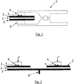
- Fig. 1 an apparatus for curing an electrically conductive adhesive 1 is shown, wherein the adhesive 1 between an electrically conductive first component 2, in particular a sheet, and an electrically conductive second component 3, in particular a second sheet, is applied.
- the device of Fig. 1 forms a pair of pliers 7, wherein on the jaws of the pliers 7 each punch 4, 6 are arranged. When the pliers 7 is closed, press the punch 4, 6 from both sides of the assembly of the first component 2, adhesive 1 and second component 3 and press so the components 2, 3 against the adhesive 1, so that the components 2, 3 are fixed and slipping of the components 2, 3 is prevented.
- the punches 4, 6 are additionally electrically connected to a voltage source, not shown, so that a current in the components 2, 3 and the adhesive 1 can be introduced by the stamp 4, 6, which hardens.
- a current in the components 2, 3 and the adhesive 1 can be introduced by the stamp 4, 6, which hardens.
- the temperature is measured by means of a temperature measuring unit 5, which is attached to the punch 4.
- the detection of the temperature and control of the power supply can be done automatically by a corresponding control unit.
- a possible temperature profile which is implemented by the control unit is in Fig. 3 shown.
- FIG. 3 illustrates an alternative embodiment of a device implementing the method according to the invention, wherein a common second component 3 is used as common ground point for at least two punches 4.
- the second component 3 is connected via an electrical connection 8 to the voltage source.
- the second pole is formed here by the at least two punches 4, which in turn press the first two components 2 with a pressure force F against the adhesive 1 to at least two splices and against the common second component 3.
- Both punches 4 can be equipped with a temperature measuring unit 5.
- the electrical power can be controlled so that the surface temperature in each individual bond corresponds to a desired temperature profile.
- the temperature T can be determined and controlled with the manipulated variable electrical power to the desired temperature profile, the respective heating curve.
- a first period A the adhesive point is heated at a constant pitch, for example at 50 degrees Celsius per minute.
- the period B represents a period in which a constant temperature T is maintained and the curing takes place predominantly.
- the supply of electrical power is turned off and open the pliers, or lifted or the stamp of the components.
- the period C then cool down the components and the adhesive.
- the duration of the period B can be varied depending on the desired degree of cure. For simple fixations, this period of time may be for example only one or a few minutes.
Landscapes
- Engineering & Computer Science (AREA)
- General Engineering & Computer Science (AREA)
- Mechanical Engineering (AREA)
- Physics & Mathematics (AREA)
- Chemical & Material Sciences (AREA)
- Organic Chemistry (AREA)
- Plasma & Fusion (AREA)
- Thermal Sciences (AREA)
- Fluid Mechanics (AREA)
- Adhesives Or Adhesive Processes (AREA)
Description
- Die vorliegende Erfindung betrifft ein Verfahren zum Aushärten eines elektrisch leitenden Klebstoffes, wobei der Klebstoff zwischen einem ersten Bauteil und einem zweiten Bauteil angeordnet ist.
- Es ist bekannt Klebstoff zwischen zwei Bauteilen zu verwenden um diese miteinander zu verbinden, insbesondere ist der Einsatz von thermisch aushärtenden Klebstoffen zum Verbinden von flachen Karosseriebauteilen, speziell von Blechen, in der Automobilindustrie bekannt. Zur raschen Fixierung der Karosseriebauteile werden diese bei einem Klebeprozess üblicherweise durch zusätzliche Hilfsmittel wie Schrauben, Nieten oder Schweißen aneinander fixiert, bis es in einem nachfolgenden Schritt zur Aushärtung des Klebstoffes in einem Ofen kommt.
- Übliche Klebstoffe verlangen dabei eine lange Vorwärmzeit und Aushärtzeit und erfordern daher zeitintensive Prozesse.
- Weiters ist, aus der
DE 10 2013 003 912 A1 , die Verwendung von elektrisch leitfähigen Klebstoffen bekannt. Diese ermöglichen durch Hindurchleiten von elektrischem Strom durch den Klebstoff ein Aushärten des Klebstoffes. Dazu ist es jedoch erforderlich das der Klebstoff, insbesondere eine aufgebrachte Kleberaupe, zur Einleitung des Stromes von außen zugänglich ist. Auch müssen dazu umständlicherweise Elektroden in die Klebstoffraupe geführt werden. - Es ist eine Aufgabe der Erfindung, ein Verfahren zum Aushärten eines elektrisch leitenden Klebstoffes anzugeben, das ein rasches Aushärten des Klebstoffes ermöglicht und dabei einfach und prozesssicher angewendet werden kann. Die Lösung der Aufgabe erfolgt durch ein Verfahren mit den Merkmalen von Anspruch 1. Erfindungsgemäß werden elektrisch leitfähige Bauteile genutzt, beispielsweise Bleche für den Karosseriebau, um Strom zu einem zwischen den Bauteilen eingebrachten Klebstoff zu leiten. Dazu wird ein Stempel auf das erste Bauteil gedrückt, so dass dieses gegen den Klebstoff und das zweite Bauteil gepresst wird und somit die Bauteile fixiert, einen Anpressdruck für die Klebung liefert und zudem als Spannungspol zur Einleitung eines Stroms von einer Spannungsquelle in die Bauteile und somit den elektrisch leitfähigen Klebstoff genutzt wird. Der zweite Pol der Spannungsquelle, insbesondere ein Massepunkt, liegt dazu am zweiten Bauteil an. Durch den so eingeführten Strom wird der Klebstoff über die elektrische Verlustleistung erhitzt und erfolgt eine rasche Aushärtung des Klebstoffs, insbesondere ohne Verwendung von zusätzlichen temporären Befestigungsmitteln und ohne den Klebstoff direkt von außen kontaktieren zu müssen.
- Hierfür verwendete Klebstoffe können zum Beispiel Harze sein, und können beispielsweise ihre elektrische Leitfähigkeit durch Einbringen von Metall- oder Kohlenstoff-Pulvern oder anderen elektrisch leitfähigen Zusatzstoffen wie Amiden oder Sulfiden erhalten haben.
- Der eingebrachte Strom kann ein Wechselstrom, Gleichstrom oder auch gepulster Gleichstrom sein.
- Weiterbildungen der Erfindung sind in den abhängigen Ansprüchen, der Beschreibung sowie den beigefügten Zeichnungen angegeben.
- Bevorzugt umfasst der Stempel eine Temperaturmesseinheit. Die Vorrichtung umfasst dann bevorzugt eine Einheit zur Auswertung der Temperaturmesswerte und zur Steuerung oder Regelung der Temperatur oder des Temperaturverlaufs an der Temperaturmesseinheit und somit am Klebstoff, um ein optimales Aushärten zu erreichen.
- Bevorzugt ist der zweite Pol durch einen weiteren Stempel ausgebildet, wobei der weitere Stempel dazu ausgebildet ist, eine Druckkraft auf das zweite Bauteil in Richtung zum ersten Bauteil auszuüben. Die beiden Stempel drücken daher gegeneinander.
- Besonders bevorzugt sind der Stempel und der weitere Stempel Teile einer Zange. Die erfindungsgemäße Vorrichtung umfasst daher eine Zange mit den beiden Stempeln, so dass das Andrücken der Stempel auf die Bauteile besonders einfach ist.
- Auch der weitere Stempel kann eine eigene Temperaturmesseinheit umfassen.
- Bevorzugt liegen am ersten Bauteil und/oder am zweiten Bauteil mehrere Klebestellen an. Ein Bauteil wird dann als Pol für mehrere Klebstellen genutzt.
- Besonders bevorzugt ist das zweite Bauteil als gemeinsamer Massepunkt eingerichtet für zumindest zwei Stempel. Die zumindest zwei Stempel liegen dann am ersten Bauteil an und können ein oder mehrere erste Bauteile niederdrücken.
- Besonders bevorzugt liegen die zumindest zwei Stempel an zumindest zwei verschiedenen ersten Bauteilen an, und sind dazu eingerichtet, jeweils eine Druckkraft auf die verschiedenen ersten Bauteile in Richtung zum zweiten Bauteil auszuüben, um über die Stempel als erster Pol und den am zweiten Bauteil anliegenden zweiten Pol Strom in die Bauteile und über die Bauteile jeweils in den Klebstoff zu führen.
- Der Strom kann über die zumindest zwei Stempel zeitlich abwechselnd, insbesondere getaktet, geführt werden. Dies ist vor allem dann notwendig, wenn nur eine gemeinsame Zuleitung der Energie für mehrere elektrisch parallel geschaltete Stempel als erster Pol erfolgt. Da in den einzelnen Klebestellen unterschiedliche elektrische Übergangswiderstände herrschen können, würden Klebestellen mit einem niedrigeren Übergangswiderstand die Stromquelle unnötig belasten bzw. Klebestellen, die einen hohen Übergangswiderstand aufweisen, nicht oder erst später ausgehärtet sein, wenn der Strom über eine gemeinsame Zuleitung gleichzeitig an beide Stempel geführt würde.
Bevorzugt wird das Taktverhältnis, also der Takt der Umschaltung der Stromquelle zu den verschiedenen Klebestellen bzw. Stempeln, in Abhängigkeit der Temperatur oder des Temperaturverlaufes der in den Stempeln und/oder den Bauteilen gemessenen Temperaturen bestimmt.
In einer anderen Ausführungsform wird der Strom zu den zumindest zwei Stempeln unabhängig voneinander geführt. Für jeden Stempel erfolgt die Energiezuführung somit separat und jeder Stromkreis eines jeden Stempels kann separat geregelt werden, um einen gewünschten Temperatur- und Aushärteverlauf an jeder Klebestelle zu erreichen.
Ein Takten der Energie, also Umschalten der Energie von einem Stempel zum anderen, ist hier nicht erforderlich. - Bevorzugt umfasst der Stempel eine Temperaturmesseinheit und der Strom, der in den Klebstoff geführt wird, wird so geregelt, dass an der Temperaturmesseinheit eine bestimmte Temperatur oder ein bestimmter Temperaturverlauf anliegt. Die Regelung des Stromes kann beispielsweise als PWM-Regelung (Puls-Weiten-Modulation) erfolgen. Wenn mehrere Stempel verwendet werden kann der Strom wie oben beschrieben über einen gemeinsamen Stromkreislauf, beispielsweise getaktet, zugeführt werden oder auch über mehrere separate Stromkreise.
- Die Erfindung wird im Folgenden beispielhaft unter Bezugnahme auf die Zeichnungen beschrieben.
- Fig. 1
- ist eine schematische Seitenansicht einer das erfindungsgemäße Verfahren ausführenden Vorrichtung.
- Fig. 2
- ist eine schematische Seitenansicht einer weiteren das erfindungsgemäße Verfahren ausführenden Vorrichtung.
- Fig. 3
- zeigt einen möglichen Temperaturverlauf in einer Klebestelle in einem erfindungsgemäßen Verfahren.
- In
Fig. 1 ist eine das erfindungsgemäße Verfahren ausführende Vorrichtung zum Aushärten eines elektrisch leitenden Klebstoffes 1 dargestellt, wobei der Klebstoff 1 zwischen einem elektrisch leitfähigen ersten Bauteil 2, insbesondere einem Blech, und einem elektrisch leitfähigen zweiten Bauteil 3, insbesondere einem zweiten Blech, aufgebracht ist, dargestellt. Die Vorrichtung derFig. 1 bildet eine Zange 7, wobei an den Greifbacken der Zange 7 jeweils Stempel 4, 6 angeordnet sind. Wenn die Zange 7 geschlossen wird, drücken die Stempel 4, 6 von beiden Seiten auf die Anordnung aus erstem Bauteil 2, Klebstoff 1 und zweitem Bauteil 3 und pressen so die Bauteile 2, 3 gegen den Klebstoff 1, so dass die Bauteile 2, 3 fixiert werden und ein verrutschen der Bauteile 2, 3 verhindert wird. Dabei sind die Stempel 4, 6 zusätzlich elektrisch mit einer nicht dargestellten Spannungsquelle verbunden, so dass durch die Stempel 4, 6 ein Strom in die Bauteile 2, 3 und den Klebstoff 1 eingebracht werden kann, der dabei aushärtet.
Beim Einbringen des Stromes wird, zum Erfassen der dabei entstehenden Wärme am ersten Bauteil 2, die Temperatur mittels einer Temperaturmesseinheit 5 gemessen, die am Stempel 4 angebracht ist. Die Erfassung der Temperatur und Regelung der Stromzuführung kann durch eine entsprechende Regelungseinheit automatisiert erfolgen. Ein möglicher Temperaturverlauf der durch die Regelungseinheit umgesetzt wird, ist inFig. 3 dargestellt. -
Fig. 2 stellt eine alternative Ausführungsform einer das erfindungsgemäße Verfahren ausführenden Vorrichtung dar, wobei ein gemeinsames zweites Bauteil 3 als gemeinsamer Massepunkt für zumindest zwei Stempel 4 verwendet wird. Das zweite Bauteil 3 ist dazu über einen elektrischen Anschluss 8 an die Spannungsquelle angeschlossen. Der zweite Pol wird hier durch die zumindest zwei Stempel 4 gebildet, die wiederum die beiden ersten Bauteile 2 mit einer Druckkraft F gegen den Klebstoff 1 an zumindest zwei Klebestellen und gegen das gemeinsame zweite Bauteil 3 pressen. Beide Stempel 4 können mit einer Temperaturmesseinheit 5 ausgestattet sein. In jeder Klebestelle kann die elektrische Leistung so geregelt sein, dass die Oberflächentemperatur in jeder einzelnen Klebstelle einem gewünschten Temperaturverlauf entspricht.
Fig. 3 stellt einen gewünschten Temperaturverlauf an einer Klebstelle bzw. an der Oberfläche eines Bauteils 2 dar, wobei vertikal die Temperatur T und horizontal die Zeit t angegeben ist. Über den oder die Temperatursensoren 5 - sieheFig. 1 und 2 ., kann jeweils die Temperatur T bestimmt werden und mit der Stellgröße elektrische Leistung auf den gewünschten Temperaturverlauf, die jeweilige Aufheizkurve, geregelt werden. Im dargestellten Beispiel wird in einem ersten Zeitabschnitt A die Klebstelle mit konstanter Steigung aufgeheizt, z.B. mit 50 Grad Celsius pro Minute. Der Zeitabschnitt B repräsentiert eine Zeitdauer in welcher eine konstante Temperatur T gehalten wird und die Aushärtung überwiegend stattfindet. Am Ende des Zeitabschnitts B wird die Zuführung der elektrischen Leistung abgestellt und die Zange geöffnet, bzw. der oder die Stempel von den Bauteilen abgehoben. Im Zeitabschnitt C kühlen daraufhin die Bauteile und der Klebstoff ab. Die Dauer des Zeitabschnitts B kann je nach gewünschtem Aushärtegrad variiert werden. Für einfache Fixierungen kann diese Zeitdauer beispielsweise nur eine oder wenige Minuten betragen. -
- 1
- Klebstoff
- 2
- erstes Bauteil
- 3
- zweites Bauteil
- 4
- Stempel
- 5
- Temperaturmesseinheit
- 6
- weiterer Stempel
- 7
- Zange
- 8
- elektrischer Anschluss
- F
- Druckkraft
- T
- Temperaturachse
- t
- Zeitachse
- A
- Zeitabschnitt
- B
- Zeitabschnitt
- C
- Zeitabschnitt
Claims (11)
- Verfahren zur Herstellung einer Klebeverbindung zwischen einem ersten Bauteil (2) und einem zweiten Bauteil (3) mittels eines elektrisch leitenden Klebstoffes (1),
dadurch gekennzeichnet, dass der Klebstoff (1) zwischen die Bauteile (2, 3) eingebrachten wird, mittels eines Stempels (4) eine Druckkraft (F) auf das erste Bauteil (2) in Richtung zum zweiten Bauteil (3) ausgeübt wird und über den Stempel (4) als erster Pol und einen am zweiten Bauteil (3) anliegenden zweiten Pol ein Strom in die Bauteile (2, 3) und über die Bauteile (2, 3) in den Klebstoff (1) geführt wird, so dass der Klebstoff erhitzt wird und aushärtet. - Verfahren nach Anspruch 1,
dadurch gekennzeichnet, dass der Stempel (4) eine Temperaturmesseinheit (5) umfasst und der Strom der in den Klebstoff (1) geführt wird so geregelt wird, dass an der Temperaturmesseinheit (5) eine bestimmte Temperatur oder ein bestimmter Temperaturverlauf anliegt. - Verfahren nach zumindest einem der vorhergehenden Ansprüche,
dadurch gekennzeichnet, dass der zweite Pol durch einen weiteren Stempel (6) ausgebildet ist, wobei der weitere Stempel (6) dazu ausgebildet ist, eine Druckkraft auf das zweite Bauteil (3) in Richtung zum ersten Bauteil (2) auszuüben. - Verfahren nach Anspruch 3,
dadurch gekennzeichnet, dass der Stempel (4) und der weitere Stempel (6) Teile einer Zange (7) sind. - Verfahren nach Anspruch 3 oder 4,
dadurch gekennzeichnet, dass der weitere Stempel (6) eine Temperaturmesseinheit (5) umfasst. - Verfahren nach zumindest einem der vorhergehenden Ansprüche,
dadurch gekennzeichnet, dass am ersten Bauteil (2) und/oder am zweiten Bauteil (3) Klebstoff (1) an mehreren Klebestellen anliegt. - Verfahren nach zumindest einem der vorhergehenden Ansprüche,
dadurch gekennzeichnet, dass das zweite Bauteil (3) als gemeinsamer Massepunkt verwendet wird für zumindest zwei Stempel (4). - Verfahren nach Anspruch 7,
dadurch gekennzeichnet, dass die zumindest zwei Stempel (4) an zumindest zwei verschiedenen ersten Bauteilen (2) anliegen, und dazu eingerichtet sind, jeweils eine Druckkraft (F) auf die verschiedenen ersten Bauteile (2) in Richtung zum zweiten Bauteil (3) auszuüben und über die Stempel (4) als erster Pol und den am zweiten Bauteil (3) anliegenden zweiten Pol ein Strom in die Bauteile (2, 3) und über die Bauteile (2, 3) jeweils in den Klebstoff (1) geführt werden kann. - Verfahren nach Anspruch 8,
dadurch gekennzeichnet, dass der Strom über die zumindest zwei Stempel (4) zeitlich abwechselnd , insbesondere getaktet geführt wird. - Verfahren nach Anspruch 9,
dadurch gekennzeichnet, dass das Taktverhältnis in Abhängigkeit der Temperatur oder des Temperaturverlaufes der in den Stempeln (4, 6) und oder den Bauteilen (2, 3) gemessenen Temperaturen bestimmt wird. - Verfahren nach Anspruch 8,
dadurch gekennzeichnet, dass Strom zu den zumindest zwei Stempeln (4) unabhängig voneinander geführt wird.
Priority Applications (1)
| Application Number | Priority Date | Filing Date | Title |
|---|---|---|---|
| EP17179529.7A EP3267048A1 (de) | 2014-04-29 | 2015-04-20 | Vorrichtung zum aushärten eines elektrisch leitenden klebstoffes |
Applications Claiming Priority (1)
| Application Number | Priority Date | Filing Date | Title |
|---|---|---|---|
| DE102014208094.0A DE102014208094A1 (de) | 2014-04-29 | 2014-04-29 | Vorrichtung zum Aushärten eines elektrisch leitenden Klebstoffes |
Related Child Applications (2)
| Application Number | Title | Priority Date | Filing Date |
|---|---|---|---|
| EP17179529.7A Division-Into EP3267048A1 (de) | 2014-04-29 | 2015-04-20 | Vorrichtung zum aushärten eines elektrisch leitenden klebstoffes |
| EP17179529.7A Division EP3267048A1 (de) | 2014-04-29 | 2015-04-20 | Vorrichtung zum aushärten eines elektrisch leitenden klebstoffes |
Publications (2)
| Publication Number | Publication Date |
|---|---|
| EP2940321A1 EP2940321A1 (de) | 2015-11-04 |
| EP2940321B1 true EP2940321B1 (de) | 2017-09-13 |
Family
ID=53487170
Family Applications (2)
| Application Number | Title | Priority Date | Filing Date |
|---|---|---|---|
| EP17179529.7A Withdrawn EP3267048A1 (de) | 2014-04-29 | 2015-04-20 | Vorrichtung zum aushärten eines elektrisch leitenden klebstoffes |
| EP15164224.6A Not-in-force EP2940321B1 (de) | 2014-04-29 | 2015-04-20 | Vorrichtung zum aushärten eines elektrisch leitenden klebstoffes |
Family Applications Before (1)
| Application Number | Title | Priority Date | Filing Date |
|---|---|---|---|
| EP17179529.7A Withdrawn EP3267048A1 (de) | 2014-04-29 | 2015-04-20 | Vorrichtung zum aushärten eines elektrisch leitenden klebstoffes |
Country Status (4)
| Country | Link |
|---|---|
| US (2) | US9757932B2 (de) |
| EP (2) | EP3267048A1 (de) |
| CN (1) | CN105041803B (de) |
| DE (1) | DE102014208094A1 (de) |
Families Citing this family (2)
| Publication number | Priority date | Publication date | Assignee | Title |
|---|---|---|---|---|
| US20180169961A1 (en) * | 2016-12-15 | 2018-06-21 | GM Global Technology Operations LLC | System and method for bonding structures |
| DE102024126854A1 (de) | 2024-09-18 | 2026-03-19 | HELLA GmbH & Co. KGaA | Verfahren zur Herstellung einer Klebeverbindung |
Family Cites Families (16)
| Publication number | Priority date | Publication date | Assignee | Title |
|---|---|---|---|---|
| GB737374A (en) * | 1951-07-11 | 1955-09-28 | Nat Res Dev | Improvements in or relating to the curing of resins and resinous materials |
| DE4332807C2 (de) * | 1992-10-20 | 2002-07-18 | Schlattl Werner Bavaria Tech | Opto-elektrischer Sensor |
| WO1994025273A1 (en) * | 1993-04-28 | 1994-11-10 | Leonte Oana M | Bonding method and system using electric current |
| DE4328337C1 (de) * | 1993-08-24 | 1994-12-15 | Siemens Ag | Verfahren zur Bestimmung der Temperatur an einer Punktschweißverbindung sowie Anwendung des Verfahrens zur Beurteilung der Qualität der Punktschweißverbindung |
| US20060134449A1 (en) * | 2004-12-20 | 2006-06-22 | Sigler David R | Weldable metal composites and methods |
| DE102007007617A1 (de) * | 2007-02-13 | 2008-08-14 | Tesa Ag | Intrinsisch erwärmbare heißschmelzklebrige Flächengebilde |
| US7877850B2 (en) * | 2007-03-27 | 2011-02-01 | GM Global Technology Operations LLC | Method for positioning and joining panels |
| DE102008015204A1 (de) | 2008-03-20 | 2009-09-24 | Still Sas | Flurförderzeug mit einem Batteriefach und einem Batteriefachdeckel |
| DE102009028583A1 (de) * | 2009-08-17 | 2011-02-24 | Robert Bosch Gmbh | Bauteilverbund sowie Verfahren zum Herstellen eines Bauteilverbundes |
| JP5468350B2 (ja) * | 2009-10-23 | 2014-04-09 | マツダ株式会社 | 異種金属板の接合方法 |
| DE102011101751A1 (de) * | 2010-05-21 | 2011-12-01 | Gm Global Technology Operations Llc (N.D.Ges.D. Staates Delaware) | Schweißsystem |
| DE202011001607U1 (de) * | 2011-01-17 | 2011-04-07 | Ifu Diagnostic Systems Gmbh | Anordnung zur online-Charakterisierung von Punktschweißnähten in Schweißrobotern |
| DE102011085412B4 (de) * | 2011-10-28 | 2017-12-21 | Lisa Dräxlmaier GmbH | Verfahren zum Herstellen eines Fahrzeugbauteils mit mehreren Schichten sowie Vorrichtung zum Applizieren eines Schmelzklebstoffs |
| DE102013003912A1 (de) | 2012-03-08 | 2013-09-12 | Faurecia Exteriors Gmbh | Verkleben von Kunststoffbauteilen mittels elektrisch leitfähigem Mehrkomponenten-Klebstoff |
| DE102012106378B4 (de) * | 2012-07-16 | 2019-12-19 | Thyssenkrupp Steel Europe Ag | Verfahren und Vorrichtung zum Fügen eines Verbundblechteils und gefügte Blechkonstruktion |
| CN102794557A (zh) * | 2012-08-30 | 2012-11-28 | 上海交通大学 | 一种用于提高差厚多层板薄板侧电阻点焊熔核尺寸的方法 |
-
2014
- 2014-04-29 DE DE102014208094.0A patent/DE102014208094A1/de not_active Withdrawn
-
2015
- 2015-04-20 EP EP17179529.7A patent/EP3267048A1/de not_active Withdrawn
- 2015-04-20 EP EP15164224.6A patent/EP2940321B1/de not_active Not-in-force
- 2015-04-27 US US14/696,738 patent/US9757932B2/en not_active Expired - Fee Related
- 2015-04-27 CN CN201510204787.8A patent/CN105041803B/zh not_active Expired - Fee Related
-
2017
- 2017-05-05 US US15/587,768 patent/US20170239928A1/en not_active Abandoned
Non-Patent Citations (1)
| Title |
|---|
| None * |
Also Published As
| Publication number | Publication date |
|---|---|
| US20150306863A1 (en) | 2015-10-29 |
| US9757932B2 (en) | 2017-09-12 |
| CN105041803B (zh) | 2018-09-25 |
| CN105041803A (zh) | 2015-11-11 |
| EP2940321A1 (de) | 2015-11-04 |
| DE102014208094A1 (de) | 2015-10-29 |
| US20170239928A1 (en) | 2017-08-24 |
| EP3267048A1 (de) | 2018-01-10 |
Similar Documents
| Publication | Publication Date | Title |
|---|---|---|
| EP3433079B1 (de) | Verfahren zum verbinden zweier fügeelemente | |
| DE10060390B4 (de) | Stanznietverfahren | |
| DE102013108563A1 (de) | Verfahren und Vorrichtung zum Widerstandsschweißen von Sandwichblechen | |
| EP1772635A2 (de) | Verbindungselement und Verfahren zu seiner Befestigung auf einer Oberfläche | |
| DE102013207284A1 (de) | Setz-Schweiß-Gerät, modulare Komponenten davon sowie ein mit ihm durchführbares kontinuierliches Verbindungsverfahren | |
| EP2739427A1 (de) | Fügen von blechartigen bauelementen mit zwischenschicht aus thermoplastischem kunststoff | |
| EP2940321B1 (de) | Vorrichtung zum aushärten eines elektrisch leitenden klebstoffes | |
| DE102014208706A1 (de) | Verfahren und Vorrichtung zum Fügen eines Verbundblechbauteils mit einem Funktionselement | |
| DE102015104635B3 (de) | Verfahren und Vorrichtung zum Widerstandsschweißen von Sandwichblechen | |
| DE102013112436A1 (de) | Mehrstufiges Widerstandsschweißen von Sandwichblechen | |
| DE102013011572A1 (de) | Verfahren zur lokalen und verzugsfreien Wärmebehandlung von Blech- oder blechartigen Bauteilen durch lokale Widerstandserwärmung | |
| EP3140069A1 (de) | Verfahren und vorrichtung zum fügen eines verbundblechbauteils mit einem weiteren bauteil | |
| DE102017126117A1 (de) | Zusammenfügen eines hybrid-werkstücks | |
| DE112011105617T5 (de) | Elektrische Heizvorrichtung | |
| DE102014109523A1 (de) | Verfahren zur Verbindung von zwei Bauteilen | |
| WO2015018716A1 (de) | Thermische abschirmvorrichtung für eine probecard und entsprechende probecardanordnung | |
| DE102018100742A1 (de) | Heizeinrichtung mit einer Mehrzahl von elektrischen Flächenheizelementen | |
| WO2013124181A1 (de) | Verfahren und vorrichtung zum konditionieren von elektroden | |
| EP3799522A1 (de) | Verfahren und vorrichtung zur elektrischen widerstandserwärmung | |
| DE102015109289B3 (de) | Verfahren und Vorrichtung zum Einbringen von Öffnungen in Faserhalbzeuge | |
| EP2722252B1 (de) | Heizvorrichtung für ein Lenkrad eines Kraftfahrzeugs, Kraftfahrzeug und entsprechendes Verfahren | |
| DE102005056808A1 (de) | Widerstandsschweißverfahren | |
| DE10218560B4 (de) | Verfahren zum Herstellen eines harzgebundenen Formteils | |
| DE102018104701A1 (de) | Verfahren zur mechanischen Verbindung und Vorrichtung zur Durchführung des Verfahrens | |
| EP3375251B1 (de) | Verfahren zur herstellung einer elektrischen heizung |
Legal Events
| Date | Code | Title | Description |
|---|---|---|---|
| PUAI | Public reference made under article 153(3) epc to a published international application that has entered the european phase |
Free format text: ORIGINAL CODE: 0009012 |
|
| AK | Designated contracting states |
Kind code of ref document: A1 Designated state(s): AL AT BE BG CH CY CZ DE DK EE ES FI FR GB GR HR HU IE IS IT LI LT LU LV MC MK MT NL NO PL PT RO RS SE SI SK SM TR |
|
| AX | Request for extension of the european patent |
Extension state: BA ME |
|
| 17P | Request for examination filed |
Effective date: 20160323 |
|
| RBV | Designated contracting states (corrected) |
Designated state(s): AL AT BE BG CH CY CZ DE DK EE ES FI FR GB GR HR HU IE IS IT LI LT LU LV MC MK MT NL NO PL PT RO RS SE SI SK SM TR |
|
| RIC1 | Information provided on ipc code assigned before grant |
Ipc: F16B 11/00 20060101AFI20170223BHEP |
|
| GRAP | Despatch of communication of intention to grant a patent |
Free format text: ORIGINAL CODE: EPIDOSNIGR1 |
|
| INTG | Intention to grant announced |
Effective date: 20170419 |
|
| GRAS | Grant fee paid |
Free format text: ORIGINAL CODE: EPIDOSNIGR3 |
|
| GRAA | (expected) grant |
Free format text: ORIGINAL CODE: 0009210 |
|
| AK | Designated contracting states |
Kind code of ref document: B1 Designated state(s): AL AT BE BG CH CY CZ DE DK EE ES FI FR GB GR HR HU IE IS IT LI LT LU LV MC MK MT NL NO PL PT RO RS SE SI SK SM TR |
|
| REG | Reference to a national code |
Ref country code: GB Ref legal event code: FG4D Free format text: NOT ENGLISH |
|
| REG | Reference to a national code |
Ref country code: CH Ref legal event code: EP |
|
| REG | Reference to a national code |
Ref country code: IE Ref legal event code: FG4D Free format text: LANGUAGE OF EP DOCUMENT: GERMAN |
|
| REG | Reference to a national code |
Ref country code: AT Ref legal event code: REF Ref document number: 928449 Country of ref document: AT Kind code of ref document: T Effective date: 20171015 |
|
| REG | Reference to a national code |
Ref country code: DE Ref legal event code: R096 Ref document number: 502015001829 Country of ref document: DE |
|
| REG | Reference to a national code |
Ref country code: NL Ref legal event code: MP Effective date: 20170913 |
|
| REG | Reference to a national code |
Ref country code: LT Ref legal event code: MG4D |
|
| PG25 | Lapsed in a contracting state [announced via postgrant information from national office to epo] |
Ref country code: HR Free format text: LAPSE BECAUSE OF FAILURE TO SUBMIT A TRANSLATION OF THE DESCRIPTION OR TO PAY THE FEE WITHIN THE PRESCRIBED TIME-LIMIT Effective date: 20170913 Ref country code: FI Free format text: LAPSE BECAUSE OF FAILURE TO SUBMIT A TRANSLATION OF THE DESCRIPTION OR TO PAY THE FEE WITHIN THE PRESCRIBED TIME-LIMIT Effective date: 20170913 Ref country code: NO Free format text: LAPSE BECAUSE OF FAILURE TO SUBMIT A TRANSLATION OF THE DESCRIPTION OR TO PAY THE FEE WITHIN THE PRESCRIBED TIME-LIMIT Effective date: 20171213 Ref country code: SE Free format text: LAPSE BECAUSE OF FAILURE TO SUBMIT A TRANSLATION OF THE DESCRIPTION OR TO PAY THE FEE WITHIN THE PRESCRIBED TIME-LIMIT Effective date: 20170913 Ref country code: LT Free format text: LAPSE BECAUSE OF FAILURE TO SUBMIT A TRANSLATION OF THE DESCRIPTION OR TO PAY THE FEE WITHIN THE PRESCRIBED TIME-LIMIT Effective date: 20170913 |
|
| PG25 | Lapsed in a contracting state [announced via postgrant information from national office to epo] |
Ref country code: BG Free format text: LAPSE BECAUSE OF FAILURE TO SUBMIT A TRANSLATION OF THE DESCRIPTION OR TO PAY THE FEE WITHIN THE PRESCRIBED TIME-LIMIT Effective date: 20171213 Ref country code: LV Free format text: LAPSE BECAUSE OF FAILURE TO SUBMIT A TRANSLATION OF THE DESCRIPTION OR TO PAY THE FEE WITHIN THE PRESCRIBED TIME-LIMIT Effective date: 20170913 Ref country code: GR Free format text: LAPSE BECAUSE OF FAILURE TO SUBMIT A TRANSLATION OF THE DESCRIPTION OR TO PAY THE FEE WITHIN THE PRESCRIBED TIME-LIMIT Effective date: 20171214 Ref country code: RS Free format text: LAPSE BECAUSE OF FAILURE TO SUBMIT A TRANSLATION OF THE DESCRIPTION OR TO PAY THE FEE WITHIN THE PRESCRIBED TIME-LIMIT Effective date: 20170913 Ref country code: ES Free format text: LAPSE BECAUSE OF FAILURE TO SUBMIT A TRANSLATION OF THE DESCRIPTION OR TO PAY THE FEE WITHIN THE PRESCRIBED TIME-LIMIT Effective date: 20170913 |
|
| PG25 | Lapsed in a contracting state [announced via postgrant information from national office to epo] |
Ref country code: NL Free format text: LAPSE BECAUSE OF FAILURE TO SUBMIT A TRANSLATION OF THE DESCRIPTION OR TO PAY THE FEE WITHIN THE PRESCRIBED TIME-LIMIT Effective date: 20170913 |
|
| REG | Reference to a national code |
Ref country code: FR Ref legal event code: PLFP Year of fee payment: 4 |
|
| PG25 | Lapsed in a contracting state [announced via postgrant information from national office to epo] |
Ref country code: RO Free format text: LAPSE BECAUSE OF FAILURE TO SUBMIT A TRANSLATION OF THE DESCRIPTION OR TO PAY THE FEE WITHIN THE PRESCRIBED TIME-LIMIT Effective date: 20170913 Ref country code: CZ Free format text: LAPSE BECAUSE OF FAILURE TO SUBMIT A TRANSLATION OF THE DESCRIPTION OR TO PAY THE FEE WITHIN THE PRESCRIBED TIME-LIMIT Effective date: 20170913 Ref country code: PL Free format text: LAPSE BECAUSE OF FAILURE TO SUBMIT A TRANSLATION OF THE DESCRIPTION OR TO PAY THE FEE WITHIN THE PRESCRIBED TIME-LIMIT Effective date: 20170913 |
|
| PG25 | Lapsed in a contracting state [announced via postgrant information from national office to epo] |
Ref country code: IT Free format text: LAPSE BECAUSE OF FAILURE TO SUBMIT A TRANSLATION OF THE DESCRIPTION OR TO PAY THE FEE WITHIN THE PRESCRIBED TIME-LIMIT Effective date: 20170913 Ref country code: SK Free format text: LAPSE BECAUSE OF FAILURE TO SUBMIT A TRANSLATION OF THE DESCRIPTION OR TO PAY THE FEE WITHIN THE PRESCRIBED TIME-LIMIT Effective date: 20170913 Ref country code: IS Free format text: LAPSE BECAUSE OF FAILURE TO SUBMIT A TRANSLATION OF THE DESCRIPTION OR TO PAY THE FEE WITHIN THE PRESCRIBED TIME-LIMIT Effective date: 20180113 Ref country code: SM Free format text: LAPSE BECAUSE OF FAILURE TO SUBMIT A TRANSLATION OF THE DESCRIPTION OR TO PAY THE FEE WITHIN THE PRESCRIBED TIME-LIMIT Effective date: 20170913 Ref country code: EE Free format text: LAPSE BECAUSE OF FAILURE TO SUBMIT A TRANSLATION OF THE DESCRIPTION OR TO PAY THE FEE WITHIN THE PRESCRIBED TIME-LIMIT Effective date: 20170913 |
|
| REG | Reference to a national code |
Ref country code: DE Ref legal event code: R097 Ref document number: 502015001829 Country of ref document: DE |
|
| PLBE | No opposition filed within time limit |
Free format text: ORIGINAL CODE: 0009261 |
|
| STAA | Information on the status of an ep patent application or granted ep patent |
Free format text: STATUS: NO OPPOSITION FILED WITHIN TIME LIMIT |
|
| PG25 | Lapsed in a contracting state [announced via postgrant information from national office to epo] |
Ref country code: DK Free format text: LAPSE BECAUSE OF FAILURE TO SUBMIT A TRANSLATION OF THE DESCRIPTION OR TO PAY THE FEE WITHIN THE PRESCRIBED TIME-LIMIT Effective date: 20170913 |
|
| 26N | No opposition filed |
Effective date: 20180614 |
|
| PG25 | Lapsed in a contracting state [announced via postgrant information from national office to epo] |
Ref country code: MT Free format text: LAPSE BECAUSE OF FAILURE TO SUBMIT A TRANSLATION OF THE DESCRIPTION OR TO PAY THE FEE WITHIN THE PRESCRIBED TIME-LIMIT Effective date: 20170913 |
|
| PG25 | Lapsed in a contracting state [announced via postgrant information from national office to epo] |
Ref country code: SI Free format text: LAPSE BECAUSE OF FAILURE TO SUBMIT A TRANSLATION OF THE DESCRIPTION OR TO PAY THE FEE WITHIN THE PRESCRIBED TIME-LIMIT Effective date: 20170913 Ref country code: MC Free format text: LAPSE BECAUSE OF FAILURE TO SUBMIT A TRANSLATION OF THE DESCRIPTION OR TO PAY THE FEE WITHIN THE PRESCRIBED TIME-LIMIT Effective date: 20170913 |
|
| REG | Reference to a national code |
Ref country code: CH Ref legal event code: PL |
|
| REG | Reference to a national code |
Ref country code: BE Ref legal event code: MM Effective date: 20180430 |
|
| REG | Reference to a national code |
Ref country code: IE Ref legal event code: MM4A |
|
| PG25 | Lapsed in a contracting state [announced via postgrant information from national office to epo] |
Ref country code: LU Free format text: LAPSE BECAUSE OF NON-PAYMENT OF DUE FEES Effective date: 20180420 |
|
| PG25 | Lapsed in a contracting state [announced via postgrant information from national office to epo] |
Ref country code: BE Free format text: LAPSE BECAUSE OF NON-PAYMENT OF DUE FEES Effective date: 20180430 Ref country code: LI Free format text: LAPSE BECAUSE OF NON-PAYMENT OF DUE FEES Effective date: 20180430 Ref country code: CH Free format text: LAPSE BECAUSE OF NON-PAYMENT OF DUE FEES Effective date: 20180430 |
|
| PG25 | Lapsed in a contracting state [announced via postgrant information from national office to epo] |
Ref country code: IE Free format text: LAPSE BECAUSE OF NON-PAYMENT OF DUE FEES Effective date: 20180420 |
|
| PGFP | Annual fee paid to national office [announced via postgrant information from national office to epo] |
Ref country code: FR Payment date: 20190418 Year of fee payment: 5 |
|
| PGFP | Annual fee paid to national office [announced via postgrant information from national office to epo] |
Ref country code: GB Payment date: 20190418 Year of fee payment: 5 |
|
| PG25 | Lapsed in a contracting state [announced via postgrant information from national office to epo] |
Ref country code: TR Free format text: LAPSE BECAUSE OF FAILURE TO SUBMIT A TRANSLATION OF THE DESCRIPTION OR TO PAY THE FEE WITHIN THE PRESCRIBED TIME-LIMIT Effective date: 20170913 |
|
| PG25 | Lapsed in a contracting state [announced via postgrant information from national office to epo] |
Ref country code: PT Free format text: LAPSE BECAUSE OF FAILURE TO SUBMIT A TRANSLATION OF THE DESCRIPTION OR TO PAY THE FEE WITHIN THE PRESCRIBED TIME-LIMIT Effective date: 20170913 |
|
| PG25 | Lapsed in a contracting state [announced via postgrant information from national office to epo] |
Ref country code: MK Free format text: LAPSE BECAUSE OF NON-PAYMENT OF DUE FEES Effective date: 20170913 Ref country code: CY Free format text: LAPSE BECAUSE OF FAILURE TO SUBMIT A TRANSLATION OF THE DESCRIPTION OR TO PAY THE FEE WITHIN THE PRESCRIBED TIME-LIMIT Effective date: 20170913 Ref country code: HU Free format text: LAPSE BECAUSE OF FAILURE TO SUBMIT A TRANSLATION OF THE DESCRIPTION OR TO PAY THE FEE WITHIN THE PRESCRIBED TIME-LIMIT; INVALID AB INITIO Effective date: 20150420 |
|
| PG25 | Lapsed in a contracting state [announced via postgrant information from national office to epo] |
Ref country code: AL Free format text: LAPSE BECAUSE OF FAILURE TO SUBMIT A TRANSLATION OF THE DESCRIPTION OR TO PAY THE FEE WITHIN THE PRESCRIBED TIME-LIMIT Effective date: 20170913 |
|
| PGFP | Annual fee paid to national office [announced via postgrant information from national office to epo] |
Ref country code: DE Payment date: 20200420 Year of fee payment: 6 |
|
| PG25 | Lapsed in a contracting state [announced via postgrant information from national office to epo] |
Ref country code: FR Free format text: LAPSE BECAUSE OF NON-PAYMENT OF DUE FEES Effective date: 20200430 |
|
| GBPC | Gb: european patent ceased through non-payment of renewal fee |
Effective date: 20200420 |
|
| PG25 | Lapsed in a contracting state [announced via postgrant information from national office to epo] |
Ref country code: GB Free format text: LAPSE BECAUSE OF NON-PAYMENT OF DUE FEES Effective date: 20200420 |
|
| REG | Reference to a national code |
Ref country code: AT Ref legal event code: MM01 Ref document number: 928449 Country of ref document: AT Kind code of ref document: T Effective date: 20200420 |
|
| PG25 | Lapsed in a contracting state [announced via postgrant information from national office to epo] |
Ref country code: AT Free format text: LAPSE BECAUSE OF NON-PAYMENT OF DUE FEES Effective date: 20200420 |
|
| REG | Reference to a national code |
Ref country code: DE Ref legal event code: R119 Ref document number: 502015001829 Country of ref document: DE |
|
| PG25 | Lapsed in a contracting state [announced via postgrant information from national office to epo] |
Ref country code: DE Free format text: LAPSE BECAUSE OF NON-PAYMENT OF DUE FEES Effective date: 20211103 |