EP2940358B1 - Dispositif pour générer un champ magnétique associé à une tige mobile d'un actionneur pneumatique et procédé de fabrication du dispositif - Google Patents
Dispositif pour générer un champ magnétique associé à une tige mobile d'un actionneur pneumatique et procédé de fabrication du dispositif Download PDFInfo
- Publication number
- EP2940358B1 EP2940358B1 EP15164733.6A EP15164733A EP2940358B1 EP 2940358 B1 EP2940358 B1 EP 2940358B1 EP 15164733 A EP15164733 A EP 15164733A EP 2940358 B1 EP2940358 B1 EP 2940358B1
- Authority
- EP
- European Patent Office
- Prior art keywords
- housing
- magnet
- mouth
- magnetic field
- annular surface
- Prior art date
- Legal status (The legal status is an assumption and is not a legal conclusion. Google has not performed a legal analysis and makes no representation as to the accuracy of the status listed.)
- Not-in-force
Links
- 238000000034 method Methods 0.000 title claims description 14
- 238000001514 detection method Methods 0.000 claims description 31
- 239000000463 material Substances 0.000 claims description 27
- 230000008878 coupling Effects 0.000 claims description 23
- 238000010168 coupling process Methods 0.000 claims description 23
- 238000005859 coupling reaction Methods 0.000 claims description 23
- 230000006835 compression Effects 0.000 claims description 5
- 238000007906 compression Methods 0.000 claims description 5
- 239000007788 liquid Substances 0.000 claims description 4
- 238000003780 insertion Methods 0.000 description 5
- 230000037431 insertion Effects 0.000 description 5
- 238000007711 solidification Methods 0.000 description 4
- 230000008023 solidification Effects 0.000 description 4
- 238000005516 engineering process Methods 0.000 description 3
- 238000004519 manufacturing process Methods 0.000 description 3
- 229920003023 plastic Polymers 0.000 description 2
- 239000004033 plastic Substances 0.000 description 2
- 230000005355 Hall effect Effects 0.000 description 1
- 238000002485 combustion reaction Methods 0.000 description 1
- 238000004891 communication Methods 0.000 description 1
- 239000012530 fluid Substances 0.000 description 1
- 238000000465 moulding Methods 0.000 description 1
- 230000010287 polarization Effects 0.000 description 1
- 229920005749 polyurethane resin Polymers 0.000 description 1
- 229920005989 resin Polymers 0.000 description 1
- 239000011347 resin Substances 0.000 description 1
- 230000000717 retained effect Effects 0.000 description 1
- 238000007789 sealing Methods 0.000 description 1
- 238000007669 thermal treatment Methods 0.000 description 1
Images


Classifications
-
- F—MECHANICAL ENGINEERING; LIGHTING; HEATING; WEAPONS; BLASTING
- F15—FLUID-PRESSURE ACTUATORS; HYDRAULICS OR PNEUMATICS IN GENERAL
- F15B—SYSTEMS ACTING BY MEANS OF FLUIDS IN GENERAL; FLUID-PRESSURE ACTUATORS, e.g. SERVOMOTORS; DETAILS OF FLUID-PRESSURE SYSTEMS, NOT OTHERWISE PROVIDED FOR
- F15B15/00—Fluid-actuated devices for displacing a member from one position to another; Gearing associated therewith
- F15B15/20—Other details, e.g. assembly with regulating devices
- F15B15/28—Means for indicating the position, e.g. end of stroke
- F15B15/2815—Position sensing, i.e. means for continuous measurement of position, e.g. LVDT
- F15B15/2861—Position sensing, i.e. means for continuous measurement of position, e.g. LVDT using magnetic means
-
- B—PERFORMING OPERATIONS; TRANSPORTING
- B29—WORKING OF PLASTICS; WORKING OF SUBSTANCES IN A PLASTIC STATE IN GENERAL
- B29C—SHAPING OR JOINING OF PLASTICS; SHAPING OF MATERIAL IN A PLASTIC STATE, NOT OTHERWISE PROVIDED FOR; AFTER-TREATMENT OF THE SHAPED PRODUCTS, e.g. REPAIRING
- B29C31/00—Handling, e.g. feeding of the material to be shaped, storage of plastics material before moulding; Automation, i.e. automated handling lines in plastics processing plants, e.g. using manipulators or robots
- B29C31/04—Feeding of the material to be moulded, e.g. into a mould cavity
-
- F—MECHANICAL ENGINEERING; LIGHTING; HEATING; WEAPONS; BLASTING
- F15—FLUID-PRESSURE ACTUATORS; HYDRAULICS OR PNEUMATICS IN GENERAL
- F15B—SYSTEMS ACTING BY MEANS OF FLUIDS IN GENERAL; FLUID-PRESSURE ACTUATORS, e.g. SERVOMOTORS; DETAILS OF FLUID-PRESSURE SYSTEMS, NOT OTHERWISE PROVIDED FOR
- F15B15/00—Fluid-actuated devices for displacing a member from one position to another; Gearing associated therewith
- F15B15/08—Characterised by the construction of the motor unit
- F15B15/10—Characterised by the construction of the motor unit the motor being of diaphragm type
-
- G—PHYSICS
- G01—MEASURING; TESTING
- G01B—MEASURING LENGTH, THICKNESS OR SIMILAR LINEAR DIMENSIONS; MEASURING ANGLES; MEASURING AREAS; MEASURING IRREGULARITIES OF SURFACES OR CONTOURS
- G01B7/00—Measuring arrangements characterised by the use of electric or magnetic techniques
- G01B7/003—Measuring arrangements characterised by the use of electric or magnetic techniques for measuring position, not involving coordinate determination
-
- G—PHYSICS
- G01—MEASURING; TESTING
- G01D—MEASURING NOT SPECIALLY ADAPTED FOR A SPECIFIC VARIABLE; ARRANGEMENTS FOR MEASURING TWO OR MORE VARIABLES NOT COVERED IN A SINGLE OTHER SUBCLASS; TARIFF METERING APPARATUS; MEASURING OR TESTING NOT OTHERWISE PROVIDED FOR
- G01D11/00—Component parts of measuring arrangements not specially adapted for a specific variable
- G01D11/24—Housings ; Casings for instruments
- G01D11/245—Housings for sensors
-
- G—PHYSICS
- G01—MEASURING; TESTING
- G01D—MEASURING NOT SPECIALLY ADAPTED FOR A SPECIFIC VARIABLE; ARRANGEMENTS FOR MEASURING TWO OR MORE VARIABLES NOT COVERED IN A SINGLE OTHER SUBCLASS; TARIFF METERING APPARATUS; MEASURING OR TESTING NOT OTHERWISE PROVIDED FOR
- G01D5/00—Mechanical means for transferring the output of a sensing member; Means for converting the output of a sensing member to another variable where the form or nature of the sensing member does not constrain the means for converting; Transducers not specially adapted for a specific variable
- G01D5/12—Mechanical means for transferring the output of a sensing member; Means for converting the output of a sensing member to another variable where the form or nature of the sensing member does not constrain the means for converting; Transducers not specially adapted for a specific variable using electric or magnetic means
- G01D5/14—Mechanical means for transferring the output of a sensing member; Means for converting the output of a sensing member to another variable where the form or nature of the sensing member does not constrain the means for converting; Transducers not specially adapted for a specific variable using electric or magnetic means influencing the magnitude of a current or voltage
-
- G—PHYSICS
- G01—MEASURING; TESTING
- G01D—MEASURING NOT SPECIALLY ADAPTED FOR A SPECIFIC VARIABLE; ARRANGEMENTS FOR MEASURING TWO OR MORE VARIABLES NOT COVERED IN A SINGLE OTHER SUBCLASS; TARIFF METERING APPARATUS; MEASURING OR TESTING NOT OTHERWISE PROVIDED FOR
- G01D5/00—Mechanical means for transferring the output of a sensing member; Means for converting the output of a sensing member to another variable where the form or nature of the sensing member does not constrain the means for converting; Transducers not specially adapted for a specific variable
- G01D5/12—Mechanical means for transferring the output of a sensing member; Means for converting the output of a sensing member to another variable where the form or nature of the sensing member does not constrain the means for converting; Transducers not specially adapted for a specific variable using electric or magnetic means
- G01D5/14—Mechanical means for transferring the output of a sensing member; Means for converting the output of a sensing member to another variable where the form or nature of the sensing member does not constrain the means for converting; Transducers not specially adapted for a specific variable using electric or magnetic means influencing the magnitude of a current or voltage
- G01D5/142—Mechanical means for transferring the output of a sensing member; Means for converting the output of a sensing member to another variable where the form or nature of the sensing member does not constrain the means for converting; Transducers not specially adapted for a specific variable using electric or magnetic means influencing the magnitude of a current or voltage using Hall-effect devices
- G01D5/145—Mechanical means for transferring the output of a sensing member; Means for converting the output of a sensing member to another variable where the form or nature of the sensing member does not constrain the means for converting; Transducers not specially adapted for a specific variable using electric or magnetic means influencing the magnitude of a current or voltage using Hall-effect devices influenced by the relative movement between the Hall device and magnetic fields
-
- B—PERFORMING OPERATIONS; TRANSPORTING
- B29—WORKING OF PLASTICS; WORKING OF SUBSTANCES IN A PLASTIC STATE IN GENERAL
- B29L—INDEXING SCHEME ASSOCIATED WITH SUBCLASS B29C, RELATING TO PARTICULAR ARTICLES
- B29L2031/00—Other particular articles
- B29L2031/748—Machines or parts thereof not otherwise provided for
-
- F—MECHANICAL ENGINEERING; LIGHTING; HEATING; WEAPONS; BLASTING
- F02—COMBUSTION ENGINES; HOT-GAS OR COMBUSTION-PRODUCT ENGINE PLANTS
- F02B—INTERNAL-COMBUSTION PISTON ENGINES; COMBUSTION ENGINES IN GENERAL
- F02B37/00—Engines characterised by provision of pumps driven at least for part of the time by exhaust
- F02B37/12—Control of the pumps
- F02B37/18—Control of the pumps by bypassing exhaust from the inlet to the outlet of turbine or to the atmosphere
- F02B37/183—Arrangements of bypass valves or actuators therefor
- F02B37/186—Arrangements of actuators or linkage for bypass valves
Definitions
- the technical purpose which forms the basis of this invention is to provide a device for generating a magnetic field associable with a movable rod of a pneumatic actuator and a method for making the device according to the invention which overcomes the above-mentioned disadvantages.
- the housing 8 extends mainly along an axis substantially perpendicular to the main plane of extension of the annular surface 11, but other mutual arrangements are possible depending on requirements.
- the magnet 10 has a cylindrical shape.
- the closing element 13 seals the housing 8 in such a way as to isolate in a fluid-tight fashion the magnet 10 present in the housing 8.
- the closing element 13 is substantially made of an elastically compressible polymeric material.
- this is a resin, preferably a polyurethane resin.
- the closing element 13, once solidified, extends substantially beyond the plane of extension of the annular surface 11 but does not extend on the annular surface 11.
- the closing element 13 as well as extending substantially beyond the plane of extension of the annular surface 11, also partly extends on the annular surface 11.
- the surface portion 16 of the annular surface 11 located between an outer edge 17 of the annular surface 11 and the closing element 13 is substantially flat.
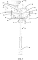
- the spring 30 is designed to oppose the variations in the volume of the first chamber 21 with variable volume. The combined action of the pressure variation and the spring 30 may therefore cause a controlled movement of the diaphragm 20 and of the coupling cup 29 and, consequently, of the movable rod 3 fixed to it.
- the method for making a device 1 for generating a magnetic field comprises first the operating step of taking a containment element 4, in turn comprising an elongate portion 5 and a flange 6 positioned at the base 7 of the elongate portion 5, a housing 8 inside the elongate portion 5, and a mouth 9 of the housing 8.
- the flange 6 comprises an annular surface 11 extending mainly flat and an inner edge 12 which surrounds the mouth 9 of the housing 8.
- the containment element 4 is made of plastic material and may be purchased on the market or prepared by moulding in one piece.
- the method according to this invention then comprises a step of inserting a magnet 10 in the housing 8 through the mouth 9 until the magnet 10 is completely inserted in the housing 8 and, preferably, until the magnet 10 is caught in the housing 8.
- the magnet 10 may be shaped to match the housing 8, whilst in the embodiments illustrated in the accompanying figures the walls of the housing 8 comprise spaced raised ribs 36, extending parallel to the line of extension of the housing 8, and which enable stable positioning of the magnet 10 in the housing 8 and prevent it from rotating relative to the housing 8.
- the magnet 10 is preferably caught between said ribs 36 even with deformation of the ribs 36.
- the polymeric material will have a viscosity suitable for allowing its insertion in the housing 8 and above all for allowing it to come out of the mouth 9 without this resulting in excessive expansion of the annular surface 11 or even outside the annular surface 11.
Landscapes
- Physics & Mathematics (AREA)
- Engineering & Computer Science (AREA)
- Mechanical Engineering (AREA)
- General Physics & Mathematics (AREA)
- Fluid Mechanics (AREA)
- General Engineering & Computer Science (AREA)
- Robotics (AREA)
- Actuator (AREA)
Claims (11)
- Un dispositif (1) pour générer un champ magnétique, pouvant être associé à une tige mobile (3) d'un actionneur pneumatique (2), comprenant un élément de confinement (4) présentant une portion allongée (5) et une bride (6) au niveau d'une base (7) de la portion allongée (5), un logement (8) à l'intérieur de la portion allongée (5), une bouche (9) du logement (8) et un aimant (10) positionné dans le logement (8), la bride (6) comprenant une surface annulaire (11) s'étendant principalement à plat avec un bord intérieur (12) entourant la bouche (9) du logement (8),
où le dispositif (1) comprend aussi un élément de fermeture (13) introduit dans le logement (8) à travers la bouche (9) du logement (8) et s'étendant à l'extérieur du logement (8) au-delà d'un plan principal d'extension de la surface annulaire (11),
caractérisé en ce que l'élément de fermeture (13) est essentiellement réalisé dans un matériau polymère compressible élastiquement qui est solidifié directement dans le logement (8) de manière à ce qu'il adhère à l'élément de confinement (4) et à ce que l'élément de fermeture (13) soit fixé à l'élément de confinement (4). - Le dispositif selon la revendication 1, caractérisé en ce que l'élément de fermeture (13) scelle le logement (8).
- Le dispositif selon l'une ou l'autre des revendications précédentes, caractérisé en ce que l'aimant (10) est entièrement introduit dans le logement (8).
- Le dispositif selon l'une quelconque des revendications précédentes, caractérisé en ce que l'aimant (10) comprend une rainure (14) sur une face (15) qui est orientée vers la bouche (9) du logement (8) dans lequel le matériau polymère solidifié est introduit.
- Le dispositif selon l'une quelconque des revendications précédentes, caractérisé en ce que l'élément de fermeture (13) s'étend en partie sur la surface annulaire (11).
- Le dispositif selon l'une quelconque des revendications précédentes, caractérisé en ce qu'une portion de surface (16) de la surface annulaire (11) située entre un bord extérieur (17) de la surface annulaire (11) et l'élément de fermeture (13) est essentiellement plate.
- Le dispositif selon l'une quelconque des revendications précédentes, caractérisé en ce que le logement (8) s'étend principalement le long d'un axe essentiellement perpendiculaire au plan principal d'extension de la surface annulaire (11).
- Un actionneur pneumatique (2) comprenant le dispositif (1) pour générer un champ magnétique selon l'une quelconque des revendications précédentes.
- L'actionneur pneumatique (2) selon la revendication 8, caractérisé en ce que l'actionneur comprend aussi une structure de confinement (19), une membrane (20) à l'intérieur de la structure de confinement (19) qui divise cette même structure de confinement (19) en une première chambre (21) et une deuxième chambre (22), un dispositif de détection (24) relié à la première chambre (21), une calotte d'accouplement (29) fixée à la membrane (20) et positionnée au niveau de la première chambre (21), un ressort (30) interposé entre la calotte d'accouplement (29) et la structure de confinement (19), une tige mobile (3) s'étendant à l'intérieur de la deuxième chambre (22) et comprenant une première extrémité (31) fixée à la membrane (20) et à la calotte d'accouplement (29) et une deuxième extrémité (32) à l'extérieur de la structure de confinement (19) et pouvant être reliée en utilisation à un dispositif à commander, le dispositif de détection (24) comprenant intérieurement un capteur de détection (27) pour détecter un champ magnétique, le dispositif (1) pour générer un champ magnétique étant positionné à l'intérieur de la première chambre (21) dans une position adjacente au dispositif de détection (24) avec l'aimant (10) couplé magnétiquement avec le capteur de détection (27) et fixé à la calotte d'accouplement (29) par des moyens d'accrochage (18) qui causent la compression de l'élément de fermeture (13) contre la calotte d'accouplement (29) et/ou la tige mobile (3).
- Un procédé de fabrication d'un dispositif (1) pour générer un champ magnétique pouvant être associé à une tige mobile (3) d'un actionneur pneumatique (2), le procédé comprenant les étapes opérationnelles consistant à :prendre un élément de confinement (4) comprenant une portion allongée (5) et une bride (6) positionnée au niveau d'une base (7) de la portion allongée (5), un logement (8) à l'intérieur de la portion allongée (5) et une bouche (9) du logement (8), la bride (6) comprenant une surface annulaire (11) s'étendant principalement à plat avec un bord intérieur (12) entourant la bouche (9) du logement (8) ;introduire un aimant (10) dans le logement (8) à travers la bouche (9) jusqu'à ce que l'aimant (10) soit entièrement introduit dans le logement (8) ;introduire dans le logement (8) à travers la bouche (9) un matériau polymère sous forme liquide ou de gel jusqu'à ce qu'une partie du matériau polymère sorte de la bouche (9) du logement (8) et s'étende au-delà d'un plan principal d'extension de la surface annulaire (11) ;faire solidifier le matériau polymère ou le laisser solidifier de manière à ce qu'il adhère à l'élément de confinement (4), créant un élément de fermeture (13) déformable élastiquement qui est fixé à l'élément de confinement (4).
- Le procédé selon la revendication 10, dans lequel l'aimant (10) comprend une rainure (14) sur une face (15) qui est orientée vers la bouche (9) du logement (8) quand l'aimant (10) est entièrement introduit dans le logement (8), et dans lequel le matériau polymère est également introduit dans la rainure (14) de l'aimant (10), l'élément de fermeture (13) déformable élastiquement étant créé à la fois à l'intérieur du logement (8) et à l'intérieur de la rainure (14) de l'aimant (10).
Applications Claiming Priority (1)
| Application Number | Priority Date | Filing Date | Title |
|---|---|---|---|
| ITVR20140110 | 2014-04-30 |
Publications (2)
| Publication Number | Publication Date |
|---|---|
| EP2940358A1 EP2940358A1 (fr) | 2015-11-04 |
| EP2940358B1 true EP2940358B1 (fr) | 2019-03-13 |
Family
ID=51033448
Family Applications (1)
| Application Number | Title | Priority Date | Filing Date |
|---|---|---|---|
| EP15164733.6A Not-in-force EP2940358B1 (fr) | 2014-04-30 | 2015-04-22 | Dispositif pour générer un champ magnétique associé à une tige mobile d'un actionneur pneumatique et procédé de fabrication du dispositif |
Country Status (2)
| Country | Link |
|---|---|
| US (1) | US9903398B2 (fr) |
| EP (1) | EP2940358B1 (fr) |
Citations (6)
| Publication number | Priority date | Publication date | Assignee | Title |
|---|---|---|---|---|
| US6157186A (en) * | 1997-06-26 | 2000-12-05 | Unisia Jecs Corporation | Rotation detecting apparatus having a casing made of resin material and having a clearance groove for absorbing thermal radiation |
| US7423421B2 (en) * | 2005-02-18 | 2008-09-09 | Woco Industrietechnik Gmbh | Device for sensing a displacement for a linear drive, and linear drive |
| US20090140730A1 (en) * | 2007-12-03 | 2009-06-04 | Robert Newman | Linear position sensor |
| US20110079138A1 (en) * | 2008-12-02 | 2011-04-07 | Storrie Willliam D | Actuator and Sensor Assembly |
| US20110262266A1 (en) * | 2010-04-23 | 2011-10-27 | Honeywell International Inc. | Linear Actuator for a Variable-Geometry Member of a Turbocharger, and a Turbocharger Incorporating Same |
| US20130092863A1 (en) * | 2010-07-07 | 2013-04-18 | Borgwarner Inc. | Valve control device |
Family Cites Families (8)
| Publication number | Priority date | Publication date | Assignee | Title |
|---|---|---|---|---|
| US6352137B1 (en) * | 2000-03-22 | 2002-03-05 | Indian Head Industries, Inc. | Brake monitoring system |
| US6472624B1 (en) * | 2000-09-26 | 2002-10-29 | Gp Companies, Inc. | In-line flow switch |
| FR2829573B1 (fr) | 2001-09-11 | 2004-01-16 | Siemens Automotive Sa | Capteur magnetique de la position d'un mobile sur une trajectoire suivie par le mobile |
| JP2005511799A (ja) * | 2001-11-16 | 2005-04-28 | イー・アイ・デュポン・ドウ・ヌムール・アンド・カンパニー | 改良されたオレフィン重合方法 |
| CN202101680U (zh) * | 2008-11-26 | 2012-01-04 | Cts公司 | 带有抗转器的线性位置传感器 |
| IT1393598B1 (it) | 2009-03-31 | 2012-04-27 | Natali | Attuatore pneumatico |
| DE102009055232A1 (de) * | 2009-12-23 | 2011-06-30 | Robert Bosch GmbH, 70469 | Magnetventil, Anker für ein Magnetventil, Verfahren zur Herstellung eines Ankers für ein Magnetventil |
| US9453854B2 (en) * | 2014-02-27 | 2016-09-27 | Kcf Technologies, Inc. | Vibration sensor |
-
2015
- 2015-04-22 EP EP15164733.6A patent/EP2940358B1/fr not_active Not-in-force
- 2015-04-28 US US14/698,076 patent/US9903398B2/en not_active Expired - Fee Related
Patent Citations (6)
| Publication number | Priority date | Publication date | Assignee | Title |
|---|---|---|---|---|
| US6157186A (en) * | 1997-06-26 | 2000-12-05 | Unisia Jecs Corporation | Rotation detecting apparatus having a casing made of resin material and having a clearance groove for absorbing thermal radiation |
| US7423421B2 (en) * | 2005-02-18 | 2008-09-09 | Woco Industrietechnik Gmbh | Device for sensing a displacement for a linear drive, and linear drive |
| US20090140730A1 (en) * | 2007-12-03 | 2009-06-04 | Robert Newman | Linear position sensor |
| US20110079138A1 (en) * | 2008-12-02 | 2011-04-07 | Storrie Willliam D | Actuator and Sensor Assembly |
| US20110262266A1 (en) * | 2010-04-23 | 2011-10-27 | Honeywell International Inc. | Linear Actuator for a Variable-Geometry Member of a Turbocharger, and a Turbocharger Incorporating Same |
| US20130092863A1 (en) * | 2010-07-07 | 2013-04-18 | Borgwarner Inc. | Valve control device |
Also Published As
| Publication number | Publication date |
|---|---|
| US20150316082A1 (en) | 2015-11-05 |
| US9903398B2 (en) | 2018-02-27 |
| EP2940358A1 (fr) | 2015-11-04 |
Similar Documents
| Publication | Publication Date | Title |
|---|---|---|
| CN106605051B (zh) | 用于内燃机的电磁阀 | |
| US8136790B2 (en) | Electromagnetic actuator for a hydraulic directional control valve | |
| CN105598909B (zh) | 用于密封圈的装配设备 | |
| US10550967B2 (en) | Connector assembly | |
| KR100882546B1 (ko) | 단위 요크 조립체를 구비한 래크/피니언 조향 기어 | |
| US9222585B2 (en) | Valve control device | |
| EP2789917B1 (fr) | Agencement de joint de soupape dynamique | |
| EP2818960B1 (fr) | Membrane pour soupape dynamique | |
| CN102155959B (zh) | 滚动接触轴承的传感器安装盖 | |
| US8477002B2 (en) | Electromagnetic hydraulic valve | |
| CN204716439U (zh) | 高压阀和包括高压阀的共轨柴油燃料喷射系统 | |
| KR20150091991A (ko) | 오일 실 | |
| JP6657767B2 (ja) | 電磁弁装置とその製造方法 | |
| RU2614651C2 (ru) | Термостатический клапан, в частности радиаторный клапан | |
| US9903398B2 (en) | Device for generating a magnetic field associable with a movable rod of a pneumatic actuator and method for making the device | |
| EP4118369B1 (fr) | Soupape comportant un élément de compensation | |
| JP2011196260A (ja) | 筒内噴射式燃料噴射弁への燃料供給装置 | |
| CN101978157B (zh) | 密封的电引线孔 | |
| EP3366913B1 (fr) | Ensemble de montage de composant de système de carburant comportant un élément de rétention | |
| US11073222B2 (en) | Electromagnetic solenoid valve | |
| US10100796B2 (en) | Reciprocating pump | |
| JP6030585B2 (ja) | オイルジェットバルブの取付方法 | |
| JP2013253566A (ja) | 燃料噴射装置 | |
| WO2018092792A1 (fr) | Joint mécanique | |
| JP6779845B2 (ja) | ピストン機械用の潤滑剤システム |
Legal Events
| Date | Code | Title | Description |
|---|---|---|---|
| PUAI | Public reference made under article 153(3) epc to a published international application that has entered the european phase |
Free format text: ORIGINAL CODE: 0009012 |
|
| AK | Designated contracting states |
Kind code of ref document: A1 Designated state(s): AL AT BE BG CH CY CZ DE DK EE ES FI FR GB GR HR HU IE IS IT LI LT LU LV MC MK MT NL NO PL PT RO RS SE SI SK SM TR |
|
| AX | Request for extension of the european patent |
Extension state: BA ME |
|
| 17P | Request for examination filed |
Effective date: 20160329 |
|
| RBV | Designated contracting states (corrected) |
Designated state(s): AL AT BE BG CH CY CZ DE DK EE ES FI FR GB GR HR HU IE IS IT LI LT LU LV MC MK MT NL NO PL PT RO RS SE SI SK SM TR |
|
| STAA | Information on the status of an ep patent application or granted ep patent |
Free format text: STATUS: EXAMINATION IS IN PROGRESS |
|
| 17Q | First examination report despatched |
Effective date: 20170509 |
|
| REG | Reference to a national code |
Ref country code: DE Ref legal event code: R079 Ref document number: 602015026167 Country of ref document: DE Free format text: PREVIOUS MAIN CLASS: F16K0027020000 Ipc: F15B0015100000 |
|
| GRAP | Despatch of communication of intention to grant a patent |
Free format text: ORIGINAL CODE: EPIDOSNIGR1 |
|
| STAA | Information on the status of an ep patent application or granted ep patent |
Free format text: STATUS: GRANT OF PATENT IS INTENDED |
|
| RIC1 | Information provided on ipc code assigned before grant |
Ipc: B29L 31/00 20060101ALI20180919BHEP Ipc: F02B 37/18 20060101ALI20180919BHEP Ipc: G01D 5/14 20060101ALI20180919BHEP Ipc: B29C 31/04 20060101ALI20180919BHEP Ipc: F15B 15/28 20060101ALI20180919BHEP Ipc: F15B 15/10 20060101AFI20180919BHEP Ipc: G01B 7/00 20060101ALI20180919BHEP Ipc: G01D 11/24 20060101ALI20180919BHEP |
|
| INTG | Intention to grant announced |
Effective date: 20181016 |
|
| GRAS | Grant fee paid |
Free format text: ORIGINAL CODE: EPIDOSNIGR3 |
|
| GRAA | (expected) grant |
Free format text: ORIGINAL CODE: 0009210 |
|
| STAA | Information on the status of an ep patent application or granted ep patent |
Free format text: STATUS: THE PATENT HAS BEEN GRANTED |
|
| AK | Designated contracting states |
Kind code of ref document: B1 Designated state(s): AL AT BE BG CH CY CZ DE DK EE ES FI FR GB GR HR HU IE IS IT LI LT LU LV MC MK MT NL NO PL PT RO RS SE SI SK SM TR |
|
| REG | Reference to a national code |
Ref country code: GB Ref legal event code: FG4D |
|
| REG | Reference to a national code |
Ref country code: CH Ref legal event code: EP Ref country code: AT Ref legal event code: REF Ref document number: 1108087 Country of ref document: AT Kind code of ref document: T Effective date: 20190315 |
|
| REG | Reference to a national code |
Ref country code: IE Ref legal event code: FG4D |
|
| REG | Reference to a national code |
Ref country code: DE Ref legal event code: R096 Ref document number: 602015026167 Country of ref document: DE |
|
| REG | Reference to a national code |
Ref country code: NL Ref legal event code: MP Effective date: 20190313 |
|
| REG | Reference to a national code |
Ref country code: LT Ref legal event code: MG4D |
|
| PG25 | Lapsed in a contracting state [announced via postgrant information from national office to epo] |
Ref country code: LT Free format text: LAPSE BECAUSE OF FAILURE TO SUBMIT A TRANSLATION OF THE DESCRIPTION OR TO PAY THE FEE WITHIN THE PRESCRIBED TIME-LIMIT Effective date: 20190313 Ref country code: FI Free format text: LAPSE BECAUSE OF FAILURE TO SUBMIT A TRANSLATION OF THE DESCRIPTION OR TO PAY THE FEE WITHIN THE PRESCRIBED TIME-LIMIT Effective date: 20190313 Ref country code: NO Free format text: LAPSE BECAUSE OF FAILURE TO SUBMIT A TRANSLATION OF THE DESCRIPTION OR TO PAY THE FEE WITHIN THE PRESCRIBED TIME-LIMIT Effective date: 20190613 Ref country code: SE Free format text: LAPSE BECAUSE OF FAILURE TO SUBMIT A TRANSLATION OF THE DESCRIPTION OR TO PAY THE FEE WITHIN THE PRESCRIBED TIME-LIMIT Effective date: 20190313 |
|
| PG25 | Lapsed in a contracting state [announced via postgrant information from national office to epo] |
Ref country code: GR Free format text: LAPSE BECAUSE OF FAILURE TO SUBMIT A TRANSLATION OF THE DESCRIPTION OR TO PAY THE FEE WITHIN THE PRESCRIBED TIME-LIMIT Effective date: 20190614 Ref country code: BG Free format text: LAPSE BECAUSE OF FAILURE TO SUBMIT A TRANSLATION OF THE DESCRIPTION OR TO PAY THE FEE WITHIN THE PRESCRIBED TIME-LIMIT Effective date: 20190613 Ref country code: HR Free format text: LAPSE BECAUSE OF FAILURE TO SUBMIT A TRANSLATION OF THE DESCRIPTION OR TO PAY THE FEE WITHIN THE PRESCRIBED TIME-LIMIT Effective date: 20190313 Ref country code: LV Free format text: LAPSE BECAUSE OF FAILURE TO SUBMIT A TRANSLATION OF THE DESCRIPTION OR TO PAY THE FEE WITHIN THE PRESCRIBED TIME-LIMIT Effective date: 20190313 Ref country code: RS Free format text: LAPSE BECAUSE OF FAILURE TO SUBMIT A TRANSLATION OF THE DESCRIPTION OR TO PAY THE FEE WITHIN THE PRESCRIBED TIME-LIMIT Effective date: 20190313 Ref country code: NL Free format text: LAPSE BECAUSE OF FAILURE TO SUBMIT A TRANSLATION OF THE DESCRIPTION OR TO PAY THE FEE WITHIN THE PRESCRIBED TIME-LIMIT Effective date: 20190313 |
|
| REG | Reference to a national code |
Ref country code: AT Ref legal event code: MK05 Ref document number: 1108087 Country of ref document: AT Kind code of ref document: T Effective date: 20190313 |
|
| PG25 | Lapsed in a contracting state [announced via postgrant information from national office to epo] |
Ref country code: SK Free format text: LAPSE BECAUSE OF FAILURE TO SUBMIT A TRANSLATION OF THE DESCRIPTION OR TO PAY THE FEE WITHIN THE PRESCRIBED TIME-LIMIT Effective date: 20190313 Ref country code: RO Free format text: LAPSE BECAUSE OF FAILURE TO SUBMIT A TRANSLATION OF THE DESCRIPTION OR TO PAY THE FEE WITHIN THE PRESCRIBED TIME-LIMIT Effective date: 20190313 Ref country code: CZ Free format text: LAPSE BECAUSE OF FAILURE TO SUBMIT A TRANSLATION OF THE DESCRIPTION OR TO PAY THE FEE WITHIN THE PRESCRIBED TIME-LIMIT Effective date: 20190313 Ref country code: ES Free format text: LAPSE BECAUSE OF FAILURE TO SUBMIT A TRANSLATION OF THE DESCRIPTION OR TO PAY THE FEE WITHIN THE PRESCRIBED TIME-LIMIT Effective date: 20190313 Ref country code: PT Free format text: LAPSE BECAUSE OF FAILURE TO SUBMIT A TRANSLATION OF THE DESCRIPTION OR TO PAY THE FEE WITHIN THE PRESCRIBED TIME-LIMIT Effective date: 20190713 Ref country code: AL Free format text: LAPSE BECAUSE OF FAILURE TO SUBMIT A TRANSLATION OF THE DESCRIPTION OR TO PAY THE FEE WITHIN THE PRESCRIBED TIME-LIMIT Effective date: 20190313 Ref country code: EE Free format text: LAPSE BECAUSE OF FAILURE TO SUBMIT A TRANSLATION OF THE DESCRIPTION OR TO PAY THE FEE WITHIN THE PRESCRIBED TIME-LIMIT Effective date: 20190313 |
|
| PG25 | Lapsed in a contracting state [announced via postgrant information from national office to epo] |
Ref country code: SM Free format text: LAPSE BECAUSE OF FAILURE TO SUBMIT A TRANSLATION OF THE DESCRIPTION OR TO PAY THE FEE WITHIN THE PRESCRIBED TIME-LIMIT Effective date: 20190313 Ref country code: PL Free format text: LAPSE BECAUSE OF FAILURE TO SUBMIT A TRANSLATION OF THE DESCRIPTION OR TO PAY THE FEE WITHIN THE PRESCRIBED TIME-LIMIT Effective date: 20190313 |
|
| REG | Reference to a national code |
Ref country code: CH Ref legal event code: PL |
|
| REG | Reference to a national code |
Ref country code: DE Ref legal event code: R097 Ref document number: 602015026167 Country of ref document: DE |
|
| REG | Reference to a national code |
Ref country code: BE Ref legal event code: MM Effective date: 20190430 |
|
| PG25 | Lapsed in a contracting state [announced via postgrant information from national office to epo] |
Ref country code: LU Free format text: LAPSE BECAUSE OF NON-PAYMENT OF DUE FEES Effective date: 20190422 Ref country code: IS Free format text: LAPSE BECAUSE OF FAILURE TO SUBMIT A TRANSLATION OF THE DESCRIPTION OR TO PAY THE FEE WITHIN THE PRESCRIBED TIME-LIMIT Effective date: 20190713 Ref country code: AT Free format text: LAPSE BECAUSE OF FAILURE TO SUBMIT A TRANSLATION OF THE DESCRIPTION OR TO PAY THE FEE WITHIN THE PRESCRIBED TIME-LIMIT Effective date: 20190313 |
|
| PLBE | No opposition filed within time limit |
Free format text: ORIGINAL CODE: 0009261 |
|
| STAA | Information on the status of an ep patent application or granted ep patent |
Free format text: STATUS: NO OPPOSITION FILED WITHIN TIME LIMIT |
|
| PG25 | Lapsed in a contracting state [announced via postgrant information from national office to epo] |
Ref country code: LI Free format text: LAPSE BECAUSE OF NON-PAYMENT OF DUE FEES Effective date: 20190430 Ref country code: MC Free format text: LAPSE BECAUSE OF FAILURE TO SUBMIT A TRANSLATION OF THE DESCRIPTION OR TO PAY THE FEE WITHIN THE PRESCRIBED TIME-LIMIT Effective date: 20190313 Ref country code: CH Free format text: LAPSE BECAUSE OF NON-PAYMENT OF DUE FEES Effective date: 20190430 Ref country code: DK Free format text: LAPSE BECAUSE OF FAILURE TO SUBMIT A TRANSLATION OF THE DESCRIPTION OR TO PAY THE FEE WITHIN THE PRESCRIBED TIME-LIMIT Effective date: 20190313 |
|
| 26N | No opposition filed |
Effective date: 20191216 |
|
| GBPC | Gb: european patent ceased through non-payment of renewal fee |
Effective date: 20190613 |
|
| PG25 | Lapsed in a contracting state [announced via postgrant information from national office to epo] |
Ref country code: SI Free format text: LAPSE BECAUSE OF FAILURE TO SUBMIT A TRANSLATION OF THE DESCRIPTION OR TO PAY THE FEE WITHIN THE PRESCRIBED TIME-LIMIT Effective date: 20190313 Ref country code: BE Free format text: LAPSE BECAUSE OF NON-PAYMENT OF DUE FEES Effective date: 20190430 |
|
| PG25 | Lapsed in a contracting state [announced via postgrant information from national office to epo] |
Ref country code: TR Free format text: LAPSE BECAUSE OF FAILURE TO SUBMIT A TRANSLATION OF THE DESCRIPTION OR TO PAY THE FEE WITHIN THE PRESCRIBED TIME-LIMIT Effective date: 20190313 |
|
| PG25 | Lapsed in a contracting state [announced via postgrant information from national office to epo] |
Ref country code: IE Free format text: LAPSE BECAUSE OF NON-PAYMENT OF DUE FEES Effective date: 20190422 Ref country code: GB Free format text: LAPSE BECAUSE OF NON-PAYMENT OF DUE FEES Effective date: 20190613 |
|
| PG25 | Lapsed in a contracting state [announced via postgrant information from national office to epo] |
Ref country code: FR Free format text: LAPSE BECAUSE OF NON-PAYMENT OF DUE FEES Effective date: 20190513 |
|
| PG25 | Lapsed in a contracting state [announced via postgrant information from national office to epo] |
Ref country code: CY Free format text: LAPSE BECAUSE OF FAILURE TO SUBMIT A TRANSLATION OF THE DESCRIPTION OR TO PAY THE FEE WITHIN THE PRESCRIBED TIME-LIMIT Effective date: 20190313 |
|
| PG25 | Lapsed in a contracting state [announced via postgrant information from national office to epo] |
Ref country code: HU Free format text: LAPSE BECAUSE OF FAILURE TO SUBMIT A TRANSLATION OF THE DESCRIPTION OR TO PAY THE FEE WITHIN THE PRESCRIBED TIME-LIMIT; INVALID AB INITIO Effective date: 20150422 Ref country code: MT Free format text: LAPSE BECAUSE OF FAILURE TO SUBMIT A TRANSLATION OF THE DESCRIPTION OR TO PAY THE FEE WITHIN THE PRESCRIBED TIME-LIMIT Effective date: 20190313 |
|
| PG25 | Lapsed in a contracting state [announced via postgrant information from national office to epo] |
Ref country code: MK Free format text: LAPSE BECAUSE OF FAILURE TO SUBMIT A TRANSLATION OF THE DESCRIPTION OR TO PAY THE FEE WITHIN THE PRESCRIBED TIME-LIMIT Effective date: 20190313 |
|
| PGFP | Annual fee paid to national office [announced via postgrant information from national office to epo] |
Ref country code: IT Payment date: 20220421 Year of fee payment: 8 Ref country code: DE Payment date: 20220428 Year of fee payment: 8 |
|
| REG | Reference to a national code |
Ref country code: DE Ref legal event code: R119 Ref document number: 602015026167 Country of ref document: DE |
|
| PG25 | Lapsed in a contracting state [announced via postgrant information from national office to epo] |
Ref country code: DE Free format text: LAPSE BECAUSE OF NON-PAYMENT OF DUE FEES Effective date: 20231103 |
|
| PG25 | Lapsed in a contracting state [announced via postgrant information from national office to epo] |
Ref country code: IT Free format text: LAPSE BECAUSE OF NON-PAYMENT OF DUE FEES Effective date: 20230422 |