EP2940522A1 - Verfahren zur erzeugung von demodulationssignalen - Google Patents
Verfahren zur erzeugung von demodulationssignalen Download PDFInfo
- Publication number
- EP2940522A1 EP2940522A1 EP15165519.8A EP15165519A EP2940522A1 EP 2940522 A1 EP2940522 A1 EP 2940522A1 EP 15165519 A EP15165519 A EP 15165519A EP 2940522 A1 EP2940522 A1 EP 2940522A1
- Authority
- EP
- European Patent Office
- Prior art keywords
- signal
- interferometer
- arm
- output
- delay
- Prior art date
- Legal status (The legal status is an assumption and is not a legal conclusion. Google has not performed a legal analysis and makes no representation as to the accuracy of the status listed.)
- Granted
Links
Images


Classifications
-
- G—PHYSICS
- G01—MEASURING; TESTING
- G01B—MEASURING LENGTH, THICKNESS OR SIMILAR LINEAR DIMENSIONS; MEASURING ANGLES; MEASURING AREAS; MEASURING IRREGULARITIES OF SURFACES OR CONTOURS
- G01B9/00—Measuring instruments characterised by the use of optical techniques
- G01B9/02—Interferometers
- G01B9/02083—Interferometers characterised by particular signal processing and presentation
-
- G—PHYSICS
- G01—MEASURING; TESTING
- G01S—RADIO DIRECTION-FINDING; RADIO NAVIGATION; DETERMINING DISTANCE OR VELOCITY BY USE OF RADIO WAVES; LOCATING OR PRESENCE-DETECTING BY USE OF THE REFLECTION OR RERADIATION OF RADIO WAVES; ANALOGOUS ARRANGEMENTS USING OTHER WAVES
- G01S17/00—Systems using the reflection or reradiation of electromagnetic waves other than radio waves, e.g. lidar systems
- G01S17/02—Systems using the reflection of electromagnetic waves other than radio waves
- G01S17/06—Systems determining position data of a target
- G01S17/08—Systems determining position data of a target for measuring distance only
- G01S17/32—Systems determining position data of a target for measuring distance only using transmission of continuous waves, whether amplitude-, frequency-, or phase-modulated, or unmodulated
- G01S17/34—Systems determining position data of a target for measuring distance only using transmission of continuous waves, whether amplitude-, frequency-, or phase-modulated, or unmodulated using transmission of continuous, frequency-modulated waves while heterodyning the received signal, or a signal derived therefrom, with a locally-generated signal related to the contemporaneously transmitted signal
-
- G—PHYSICS
- G01—MEASURING; TESTING
- G01S—RADIO DIRECTION-FINDING; RADIO NAVIGATION; DETERMINING DISTANCE OR VELOCITY BY USE OF RADIO WAVES; LOCATING OR PRESENCE-DETECTING BY USE OF THE REFLECTION OR RERADIATION OF RADIO WAVES; ANALOGOUS ARRANGEMENTS USING OTHER WAVES
- G01S7/00—Details of systems according to groups G01S13/00, G01S15/00, G01S17/00
- G01S7/48—Details of systems according to groups G01S13/00, G01S15/00, G01S17/00 of systems according to group G01S17/00
- G01S7/491—Details of non-pulse systems
- G01S7/4912—Receivers
- G01S7/4915—Time delay measurement, e.g. operational details for pixel components; Phase measurement
-
- G—PHYSICS
- G01—MEASURING; TESTING
- G01S—RADIO DIRECTION-FINDING; RADIO NAVIGATION; DETERMINING DISTANCE OR VELOCITY BY USE OF RADIO WAVES; LOCATING OR PRESENCE-DETECTING BY USE OF THE REFLECTION OR RERADIATION OF RADIO WAVES; ANALOGOUS ARRANGEMENTS USING OTHER WAVES
- G01S13/00—Systems using the reflection or reradiation of radio waves, e.g. radar systems; Analogous systems using reflection or reradiation of waves whose nature or wavelength is irrelevant or unspecified
- G01S13/02—Systems using reflection of radio waves, e.g. primary radar systems; Analogous systems
- G01S13/06—Systems determining position data of a target
- G01S13/08—Systems for measuring distance only
- G01S13/32—Systems for measuring distance only using transmission of continuous waves, whether amplitude-, frequency-, or phase-modulated, or unmodulated
- G01S13/34—Systems for measuring distance only using transmission of continuous waves, whether amplitude-, frequency-, or phase-modulated, or unmodulated using transmission of continuous, frequency-modulated waves while heterodyning the received signal, or a signal derived therefrom, with a locally-generated signal related to the contemporaneously transmitted signal
- G01S13/343—Systems for measuring distance only using transmission of continuous waves, whether amplitude-, frequency-, or phase-modulated, or unmodulated using transmission of continuous, frequency-modulated waves while heterodyning the received signal, or a signal derived therefrom, with a locally-generated signal related to the contemporaneously transmitted signal using sawtooth modulation
-
- G—PHYSICS
- G01—MEASURING; TESTING
- G01S—RADIO DIRECTION-FINDING; RADIO NAVIGATION; DETERMINING DISTANCE OR VELOCITY BY USE OF RADIO WAVES; LOCATING OR PRESENCE-DETECTING BY USE OF THE REFLECTION OR RERADIATION OF RADIO WAVES; ANALOGOUS ARRANGEMENTS USING OTHER WAVES
- G01S17/00—Systems using the reflection or reradiation of electromagnetic waves other than radio waves, e.g. lidar systems
- G01S17/02—Systems using the reflection of electromagnetic waves other than radio waves
- G01S17/06—Systems determining position data of a target
- G01S17/08—Systems determining position data of a target for measuring distance only
- G01S17/32—Systems determining position data of a target for measuring distance only using transmission of continuous waves, whether amplitude-, frequency-, or phase-modulated, or unmodulated
- G01S17/36—Systems determining position data of a target for measuring distance only using transmission of continuous waves, whether amplitude-, frequency-, or phase-modulated, or unmodulated with phase comparison between the received signal and the contemporaneously transmitted signal
Definitions
- the present invention relates to a method for generating M demodulation signals, M being a strictly positive integer.
- the invention also relates to a method for demodulating a signal to be demodulated by at least M signals obtained by the implementation of such a method, a device adapted to implement such a method for generating M demodulation signals, and a detection system comprising such a device.
- the invention applies to the field of the detection and analysis of at least one target by electromagnetic waves, for example in the context of radar or lidar applications.
- the target is for example a hard target or a diffuse target.
- Hard target is usually a solid object.
- diffuse target generally means a gas or a mixture of gases, possibly comprising particles in suspension whose dimensions are of the same order of magnitude as the wavelength of the electromagnetic waves.
- Such detection is intended for example the measurement of physical quantities relating to the atmosphere, performing a wind mapping, or the achievement of distance measurements and / or speed relative to a hard target.
- an electromagnetic wave is emitted, from a source, to the target and broadcast by said target in a broadcast wave.
- Part of the scattered wave is collected and analyzed to deduce the target characteristics that are sought.
- the analysis performed on the collected wave is a spectral analysis. More precisely, lines are sought in the spectrum of the collected wave, the frequency of said lines being representative of a magnitude relative to the target.
- spectral of a signal is meant the spectral power density of this signal.
- the frequency of the emitted wave being generally between a few gigahertz and a few hundred terahertz, it is preferable to transpose the spectrum of the collected wave at low frequencies to perform this spectral analysis, for example frequencies lower than a few gigahertz, to allow processing by the usual measuring instruments to detect the lines described above.
- the wave generated by a given source experiences, over time, fluctuations, for example intensity fluctuations and / or fluctuations in the time phase of the generated wave.
- the wave collected at a given instant has, for example, a partially decorrelated phase of the wave emitted at the same time, with part of which the collected wave is mixed.
- This decorrelation results, compared to the ideal case devoid of fluctuations, by a widening of the lines of interest in the spectrum of the beat signal, associated with a decrease in the intensity of the lines.
- the predetermined reference signal is adapted to partially compensate for the fluctuations of the wave source, in particular its phase fluctuations.
- the reference signal is not adapted to compensate for the real fluctuations of the wave source over time.
- the compensation for the widening of the lines of interest is therefore limited.
- An object of the invention is therefore to propose a method of processing the collected signal leading to a more efficient treatment of the widening of the lines of interest.
- the subject of the invention is the use of the demodulation method as defined above for determining the speed and the position of a target.
- a detection and analysis system 2 is represented on the figure 1 .
- the detection system 2 is able to interact with a target 3.
- the detection system 2 is able to emit an electromagnetic wave towards the target 3.
- the target 3 is able to diffuse the electromagnetic wave emitted by the detection system 2.
- the target 3 is for example a hard target or a diffuse target.
- Target 3 is mobile or motionless.
- the detection system 2 is adapted to receive the electromagnetic wave diffused by the target 3.
- the electromagnetic wave emitted by the detection system 2 is for example an optical wave.
- optical wave is meant an electromagnetic wave whose wavelength in vacuum is between 100 nm and 20 microns.
- the detection system 2 comprises a remote sensing device 4 with lidar technology ("light detection and ranging”) and a processing device 6 according to the invention.
- the remote sensing device 4 is adapted to transmit and receive optical waves, and to generate an electrical signal which is a function of the optical waves received.
- the processing device 6 is capable of generating a demodulation signal for demodulating said electrical signal generated by the remote sensing device 4 and for carrying out this demodulation.
- the remote sensing device 4 comprises a transmission stage 7 for transmitting an optical wave towards the target 3, and a reception stage 8 for receiving the optical wave diffused by the target 3 and generating an electrical signal which is a function of the received broadcast optical wave.
- the transmission stage 7 comprises a laser source 9 suitable for generating an optical wave, an optical amplifier 11 capable of amplifying the optical wave, and a transmitter 12 capable of transmitting the amplified optical wave towards the target 3.
- the transmission stage 7 does not include an optical amplifier.
- the laser source 9 comprises an output 9S connected by a first optical fiber 10 to an input 11 E of the amplifier 11.
- an output 11S of the amplifier 11 is connected by an optical transmission fiber 14 to an input 12E of the transmitter 12.
- the laser source 9 is suitable for generating an optical wave whose wavelength in the central vacuum is advantageously between 1.4 ⁇ m and 1.6 ⁇ m, for example equal to 1.55 ⁇ m.
- the laser source 9 preferably comprises a control unit, not shown, for modifying the frequency of the optical wave emitted by the laser source 9 over time.
- the control unit is adapted to vary over time the frequency of the wave emitted by the laser source 9 following a sawtooth profile, with an amplitude equal to a few hundred megahertz and a period equal to a few tens of microseconds.
- the control unit is also adapted to modify the amplitude of the optical wave emitted by the laser source 9 over time.
- the laser source 9 is for example a laser diode such as a distributed feedback laser diode (or DFB).
- DFB distributed feedback laser diode
- the first optical fiber 10 is preferably a polarization-maintaining fiber, advantageously a monomode polarization-maintaining fiber.
- the amplifier 11 is able to amplify the wave emitted by the laser source 9 and injected at its input 11 E.
- the amplifier 11 is adapted to provide at its output 11S an amplified wave whose frequency is substantially equal to the frequency of the wave injected at its input 11 E.
- the amplifier 11 is for example a fiber amplifier or a semiconductor Optical Amplifier (or SOA).
- the transmitter 12 is adapted to modify the amplified optical wave injected at its input 12E to confer spatial phase properties and / or spatial amplitude and / or polarization desired by a user.
- the transmitter 12 is able to focus at a predetermined distance, called "range" of the remote sensing device 4, the amplified optical wave injected at its input 12E.
- the reception stage 8 comprises a receiver 16 for receiving the scattered wave, a coupler 18 for interfering the received scattered wave with another optical wave, and a first detector 20, also called the "main detector", for detecting a optical interference signal and generate an electric current which is a function of the optical interference signal.
- the receiver 16 has an output 16S, connected to a first input 18E1 of the coupler 18 by a receiving optical fiber 22.
- the coupler 18 has a second input 18E2 connected to the output 9S of the laser source 9 by an optical fiber 23, so-called "Local oscillator fiber", adapted to convey a portion of the optical wave at the output of the laser source 9 to the second input 18E2 of the optical coupler 18.
- the first optical reception fiber 22 is preferably a polarization-maintaining fiber, advantageously a monomode polarization-maintaining fiber.
- the local oscillator fiber 23 is preferably a polarization-maintaining fiber, advantageously a monomode polarization-maintaining fiber.
- the local oscillator fiber 23 connects the second input 18E2 of the coupler 18 to the output 11S of the amplifier 11 for conveying a portion of the amplified optical wave at the output of the amplifier 11 to the second input 18E2.
- the coupler 18 further comprises a first output 18S1, connected to an input 20E of the detector 20, and a second output 18S2, not connected in this figure.
- the receiver 16 is adapted to modify the received scattered wave to provide at its output 16S an optical wave having desired spatial phase and / or spatial amplitude and / or polarization properties by a user.
- the coupler 18 has for example a coupling factor equal to 3 dB, that is to say that the coupler 18 is able to provide each of its outputs 18S1, 18S2 an optical wave equal to half the sum of the optical wave injected at its first input 18E1, and the optical wave injected at its second input 18E2.
- the main detector 20 is able to provide at its output 20S an electrical signal, also called a "signal to be demodulated", which depends on the optical signal applied to its input 20E by the first output 18S1, advantageously an electrical signal proportional to the optical power of the optical signal applied to its input 20E.
- the main detector 20 is, for example, a photodiode or a photomultiplier.
- the processing device 6 comprises an interferometer 24 for supplying a reference optical signal from a portion of the optical wave generated by the laser source 9, a second detector 26, also called a “demodulation detector” for detecting the signal optical reference and generate an electrical signal, also called “reference signal”, which is a function of the reference optical wave, and a processing unit 28 for processing the reference signal.
- the interferometer 24 comprises an input 24E, connected by an optical fiber 29, also called “demodulation fiber”, to the output 9S of the laser source 9, and an output 24S connected to an input 26E of the demodulation detector 26.
- the demodulation detector 26 further comprises an output 26S, connected to a first input 28E1 of the processing unit 28.
- the processing unit 28 further comprises a demodulation input 28E2 connected to the output 20S output of the main detector 20.
- the demodulation fiber 29 is preferably a polarization-maintaining fiber, advantageously a monomode polarization-maintaining fiber.
- the interferometer 24 comprises a first arm 30 and a second arm 32 of different lengths.
- the second arm 32 has a delay line 33 having an input 33E and an output 33S.
- the delay line 33 is capable of providing at its output 33S a signal delayed by a time delay T 0 relative to a signal applied to its input 33E.
- the delay line 33 is for example an optical fiber, preferably a monomode fiber, advantageously a monomode fiber with polarization maintenance.
- the length of the delay line 33 is preferably less than or equal to the range of the remote sensing device 4, advantageously less than one-fifth of the range, for example less than one-tenth of the range.
- the length of the delay line 33 is less than 40 meters, advantageously less than 20 meters, for example less than 10 meters.
- the interferometer 24 is such that an optical wave injected at its input 24E splits into two optical waves: a first optical wave flowing in the first arm 30 and a second optical wave flowing in the second arm 32.
- the power optical of the second optical wave is between 45% and 55% of the optical power of the first optical wave, preferably equal.
- the interferometer 24 is for example a Mach-Zehnder interferometer.
- the processing unit 28 comprises an acquisition system 34 comprising two inputs which are the inputs 28E1, 28E2 of the processing unit 28, a memory 36 and a computer 38.
- the processing unit further comprises means for seizure 40.
- the acquisition system 34 of the processing unit 28 is adapted to sample each of the electrical signals applied to its inputs 28E1, 28E2.
- the acquisition system 34 is also adapted to transmit the sampled signals to the memory 36.
- the memory 36 is adapted to store the signals sampled by the acquisition system 34.
- the computer 38 is adapted to process the data stored in the memory 36, for example processing the data according to instructions entered by a user via the input means 40.
- the computer 38 is adapted to calculate a demodulation signal from the signal applied to the first input 28E1 of the processing unit 28, and to demodulate the signal to be demodulated, applied to the demodulation input 28E2 of the processing unit 28, by the demodulation signal calculated.
- the computer 38 is adapted to synchronize with the control unit of the laser source 9.
- the computer 38 is adapted to process separately the signals received during the increasing part of the sawtooth modulation and the signals received during the decreasing part of this modulation.
- the laser source 9 emits an optical wave whose frequency is controlled by the control unit. However, the phase of the optical wave fluctuates over time.
- a first portion of the optical wave emitted by the laser source 9 propagates in the first optical fiber 10 to the amplifier 11.
- the demodulation fiber 29 propagates in the demodulation fiber 29 to the interferometer 24.
- the amplifier 11 amplifies the first part of the wave emitted by the laser source 9 and provides at its output 11S an amplified optical wave.
- the transmitter 12 transmits the amplified wave toward the target 3.
- the target 3 diffuses the amplified wave emitted by the transmitter 12.
- the spectrum of the scattered wave has properties representative of physical parameters of the target 3 such as its position or its speed.
- the time difference between the sawtooth patterns of the emitted wave and the sawtooth patterns of the scattered wave is proportional to the distance to which the target 3 is located.
- the frequency offset between the maxima of the sawtooth patterns of the emitted wave and the maxima of the sawtooth patterns of the scattered wave is proportional to the speed of the target 3.
- the receiver 16 captures a part of the wave scattered by the target 3.
- the captured wave injected into the first input 18E1 of the coupler 18 via the receiving fiber 20.
- the coupler 18 provides at its output an optical wave, for example equal to half the sum of the wave injected into the first input of the coupler 18 by the local oscillator fiber 23 and the received wave injected into the second input of the coupler 18 by the receiving fiber 20.
- the optical wave available at the output of the coupler 18 is therefore an interference optical signal between the waves injected at the first and second inputs 18E1, 18E2 of the coupler 18.
- the main detector 20 detects the interference optical signal and provides at its output a real signal, also called “signal to be demodulated", which is proportional to the squared modulus of the interference optical signal injected at the input of the detector 22.
- the signal to be demodulated is applied to the second input of the processing unit 28.
- the signal to be demodulated is acquired and sampled by the acquisition system 34 to be recorded in the memory 36.
- the signal to be demodulated has a spectrum 42, represented on the figure 2 .
- the spectrum 42 comprises a peak of interest 44, with a center frequency equal to 37.3 MHz, of amplitude equal to -132 dBm / Hz and a width at mid-height equal to 1.7 MHz, with a signal-to-signal ratio of noise equal to 11 dB.
- the spectrum 42 is obtained by transmitting an optical optical power wave equal to 200 mW to a target 3 presenting an albedo equal to 12% and 125 m apart, after application to the laser source 9 of a linear frequency modulation slope of 45 MHz / ⁇ s.
- the peak of interest 44 does not have a fineness and a signal-to-noise ratio sufficient to ensure an accurate estimate of its central frequency. An accurate estimate of the central frequency of the peak of interest 44 then leads to an accurate estimate of the speed and / or distance of the target 3.
- the sampled wave is injected at the input 24E of the interferometer 24.
- a first part of the sampled wave propagates in the first arm 30 of the interferometer 24.
- a second part of the sampled wave propagates in the second arm 32 of the interferometer 24, in particular in the delay line 33.
- the interferometer 24 provides at its output 24S an optical beacon signal, called "beat wave".
- the beat wave results from the interference between the first part of the sampled wave and the second part of the sampled wave, delayed by the delay ⁇ 0 induced by the delay line 33.
- the demodulation detector 26 detects the beat wave and supplies at its output a real signal 46, also called a "reference signal”, visible on the figure 3 and which is proportional to the modulus squared of the beat wave injected at the input of the demodulation detector 26.
- the reference signal 46 is applied to the first input of the processing unit 28.
- the reference signal 46 is acquired and sampled by the acquisition system 34 to be recorded in the memory 36.
- a user chooses a strictly positive integer K and enters it via the input means 40.
- the computer 38 then calculates a complex reference signal from the real reference signal 46.
- the computer 38 first calculates the Fourier transform of the real reference signal 46. Then the computer 38 calculates an intermediate signal, obtained by canceling certain components of the Fourier transform of the reference signal. Preferably, the computer 38 cancels components whose frequencies are of the same sign. For example, the computer 38 calculates the intermediate signal by canceling the negative frequency components of the Fourier transform of the reference signal. The calculator 38 finally calculates the complex reference signal, which is equal to the inverse Fourier transform of the intermediate signal.
- the complex reference signal is called the analytic representation of the signal.
- the complex reference signal is obtained by first calculating, in the computer 38, the Hilbert transform, conventionally known, of the real reference signal 46, then adding to the real reference signal 46 its Hilbert transform previously calculated.
- the computer 38 also cancels the zero frequency component of the Fourier transform of the real reference signal.
- S K t exp i ⁇ ⁇ t - K ⁇ ⁇ 0 - ⁇ ⁇ t - K + 1 ⁇ ⁇ 0
- the computer 32 then calculates a demodulation signal S d equal to the product of the K + 1 transition signals.
- the expression of the demodulation signal S d is analogous to that of a reference signal obtained with an interferometer whose second arm comprises a delay line introducing a delay (K + 1) ⁇ 0 between its input and its output.
- the computer 38 then calculates a demodulated signal equal to the product of the signal to be demodulated and of the demodulation signal S d , or else to the product of the signal to be demodulated and of the conjugate of the demodulation signal S d. .
- the user can adjust the value of the positive integer K so that the delay (K + 1) ⁇ 0 induced by the demodulation signal S d compensates the time decorrelation between the collected broadcast signal and the local oscillator, so to increase the signal-to-noise ratio and the fineness of the peak of interest 44.
- the demodulated signal has a spectrum 48, represented on the figure 4 .
- the spectrum 48 of the demodulated signal comprises a peak of interest 50 with a center frequency equal to 1.7 MHz, that is to say equal to the central frequency of the peak of interest 44 of the spectrum 42 of the signal to be demodulated. which was subtracted from a first frequency offset related to the propagation of the wave of the remote sensing device 4 to the target 3, then from the target 3 to the remote sensing device 4, and to which was added a second frequency shift by Doppler effect related to the speed of displacement of the target 3, here equal to 0.2 m / s.
- the peak of interest 50 of the spectrum 48 of the demodulated signal has an amplitude equal to -119 dBm, with a signal-to-noise ratio equal to 24 dB, and a half-height width of less than 200 kHz.
- the peak of interest 50 has a fineness and a signal-to-noise ratio sufficient to ensure an accurate estimate of the speed of the target 3.
- the processing device 6 comprises a second interferometer 24B, as appears in FIG. figure 5 .
- the second interferometer 24B is for example a Mach-Zehnder interferometer.
- the second interferometer 24B comprises an input 24BE, connected to the output 24S of the first interferometer 24, and a 24BS output connected to the input 26E of the demodulation detector 26.
- the second interferometer 24B comprises a first arm 30B and a second arm 32B of distinct lengths.
- the second arm 32B includes a second delay line 33B having an input 33BE and an output 33BS.
- the second delay line 33B is adapted to provide at its output 33BS a signal delayed by a second time delay ⁇ 1 relative to a signal applied to its input 33BE.
- the second delay line 33B is for example an optical fiber, preferentially a polarization-maintaining fiber, advantageously a monomode fiber with polarization maintenance.
- the length of the second delay line 33B is different from the length of the delay line 33.
- the ratio between the first delay ⁇ 0 and the second delay ⁇ 1 is greater than 5, preferably greater than 10, by example greater than 20.
- each interferometer 24, 24B is such that an optical wave injected at the input 24E, 24BE of the interferometer 24, 24B is divided into a first optical wave flowing in the first arm 30, 30B and a second optical wave flowing in the second arm 32, 32B.
- the optical power of the second optical wave is greater than the optical power of the first optical wave, advantageously two times greater, preferably five times greater, for example ten times greater.
- the first interferometer 24 provides at its output 24S a first beat optical signal resulting from the interference between the first part of the sampled wave and the second part of the sampled wave, delayed by the delay ⁇ 0 induced by the delay line 33.
- the first beat optical signal is then injected at the input 24BE of the second interferometer 24B.
- a first portion of the first beat optical signal propagates in the first arm 30B of the second interferometer 24B.
- a second part of the first beat optical signal propagates in the second arm 32B of the second interferometer 24B, in particular in the second delay line 33B.
- the second interferometer 24B provides at its output 24BS a second beat optical signal resulting from the interference between the first part of the first beat optical signal and the second part of the first beat optical wave, delayed by the delay ⁇ 1 induced by the second delay line 33B.
- the demodulation detector 26 detects the second beat optical signal and provides at its output the reference signal.
- the reference signal is an electrical signal proportional to the modulus squared of the second beat optical signal injected at the input of the demodulation detector 26.
- the user chooses first and second positive integers K 1 , K 2 , at least one of which is non-zero, and inputs them via the input means 40.
- the computer 38 then creates (K i +1) first transition signals S 1, p and (K 2 +1) second transition signals S 2, r .
- the first transition signals S 1, p are defined as the transition signals S p described above.
- the computer 38 then calculates the demodulated signal equal to the product of the signal to be demodulated by the first demodulation signal S 1, d , or by its conjugate, then by the second demodulation signal S 2, d or by its conjugate, according to the choice of the user.
- This has the effect of compensating the temporal decorrelation between the local oscillator and the collected scattered signal, which is delayed by T relative to the local oscillator.
- the delays ⁇ 0 , ⁇ 1 being different, preferably in a ratio of the first delay ⁇ 0 on the second delay ⁇ 1 greater than 5, the user can first choose the value of the integer corresponding to the largest delay among the two delays ⁇ 0 and ⁇ 1 to roughly approximate the total propagation time T, then choose the value of K 2 to approach more finely the total propagation time T after the value of K1 has been chosen.
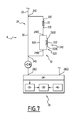
- the transmitter 12 and the receiver 16 are combined into a transceiver 42, as shown in FIG. figure 6 .
- the transceiver 42 is adapted to emit an electromagnetic wave towards the target 3.
- the transceiver 42 is also adapted to receive at least a portion of the electromagnetic wave diffused by the target 3.
- the transceiver 42 has an input-output 42ES.
- the remote sensing device 4 then comprises a circulator 44.
- the circulator 44 has an input 44E, an output 44S and an input-output 44ES.
- the circulator 44 is suitable for conveying an optical wave injected at its input 44E to its input-output 44ES.
- the circulator 44 is suitable for conveying an optical wave injected at its input-output 44ES to its output 44S.
- the input-output 44ES of the circulator 44 is connected to the input-output 42ES of the transceiver 42.
- the transceiver 42 comprises for example a lens 46 in series with a quarter wave plate 48.
- the lens 46 is for example a convergent lens.
- the circulator 44 is for example a fiber circulator or an assembly formed by a polarizer cube, a polarization separator and a wave plate.
- the local oscillator fiber is replaced by a compensation delay line 50, comprising an input 50E and a 50S output.
- the compensation delay line 50 is connected to the output 9S of the laser source 9 at a connection point 52.
- the output 50S of the compensation delay line 50 is connected to the input 24E of the interferometer 24.
- the output 50S is further connected to the second input 18E2 of the coupler 18.
- the compensation delay line 50 induces a predetermined delay R between a signal injected at its input 50E and a signal emerging from its output 50S.
- the delay R is chosen equal to the total time of propagation of a wave from the connection point 52 to the transceiver 42, and then from the transceiver 42 to the first input 18E1 of the coupler.
- the delay R allows a preliminary compensation, without calculation by the processing unit 28, of the decorrelation between the local oscillator and the signal collected by the remote sensing device 4.
- Such compensation allows the user, for a delay ⁇ 0 Given the interferometer 24, to reduce the value of the integer K which leads to a desired refinement of the peaks of interest 44. This has the effect of reducing the computation time of the computer 38.
- the detector 20 of the remote sensing device 4 is a balanced detector.
- the detector 20 comprises a first input 20E1, a second input 20E2 and an output 20S.
- the first input 20E1 is connected to the first output 18S1 of the coupler 18.
- the second input 20E2 is connected to the second output 18S2 of the coupler 18.
- the balanced detector 20 consists for example of two photodiodes of similar physical characteristics, mounted in antiparallel.
- the local oscillator is taken at the output of the amplifier 11, the connection point 52 then being located downstream of the amplifier 11.
- the processing device 6 comprises N interferometers, N being a natural integer strictly greater than 2.
- the N interferometers are then arranged successively, the output of an interferometer being connected to the output of the next interferometer.
- Each interferometer has a first arm and a second arm.
- the second arm has a delay line.
- the delay line of the i-th interferometer, i being an integer between 2 and N, comprises an input and an output, and induces a predetermined delay ⁇ i between a signal injected at its input and a signal emerging from its output.
- the delays ⁇ i induced by the interferometers are preferably two to two distinct.
- the user enters N natural numbers K 1 , K 2 ,..., K i ,..., K N , at least one of which is non-zero.
- Each natural integer entered by the user is associated with a separate interferometer.
- the computer 38 then calculates N demodulation signals.
- the processing device 6 comprises at least two nested interferometers.
- two nested interferometers is meant a first interferometer 24 and a second interferometer 240, such that one of the arms 30, 32 of the first interferometer 24 includes the second interferometer 240.
- the first interferometer is the interferometer 24 as described with respect to the figure 5 .
- the second interferometer 240 is for example a Mach-Zehnder interferometer.
- the second arm 32 of the first interferometer 24 comprises the second interferometer 240, in series with the delay line 33.
- the second interferometer 240 comprises an input 240E, connected to the output 33S of the delay line 33.
- L interferometer 240 further comprises an output 240S connected to the output 24S of the first interferometer 24.
- the second interferometer 240 comprises a first arm 300 and a second arm 320 of distinct lengths.
- the second arm 320 of the second interferometer 240 includes a delay line 330 having an input 330E and an output 330S.
- the delay line 330 is able to provide at its output 330S a signal delayed by a time delay ⁇ ' 1 with respect to a signal applied to its input 330E.
- the delay line 330 of the second interferometer 240 is, for example, an optical fiber, preferably a monomode fiber, advantageously a monomode fiber maintaining polarization.
- the length of the delay line 330 of the second interferometer 240 is preferably less than or equal to the range of the remote sensing device 4, advantageously less than one-fifth of the range, for example less than one-tenth of the range.
- the length of the delay line 330 is less than 40 meters, advantageously less than 20 meters, for example less than 10 meters.
- the length of the delay line 330 is different from the length of the delay line 33.
- the ratio between the largest of the delay ⁇ 0 of the delay line 33 of the first interferometer 24 and the delay ⁇ 1 of the delay line 330 of the second interferometer 240, and the smallest of these delays ⁇ 0 , ⁇ ' 1 is greater than 2, preferably greater than 5, for example greater than 10.
- the second interferometer 240 is such that an optical wave injected at its input 240E splits into two optical waves: a first optical wave circulating in the first arm 300 and a second optical wave flowing in the second arm 320.
- the optical power of the second optical wave is then greater than the optical power of the first optical wave, preferably two times greater, preferably five times greater, for example ten times higher.
- the sampled wave is conveyed by the demodulation fiber 29 from the laser source 9.
- the sampled wave is injected at the input 24E of the interferometer 24.
- a first part of the sampled wave propagates in the first arm 30 of the interferometer 24.
- a second part of the sampled wave propagates in the second arm 32 of the interferometer 24.
- the second part of the sampled wave propagates in the delay line 33 to form a delayed wave.
- the delayed wave is then injected at the input 240E of the second interferometer 240.
- a first part of the delayed wave propagates in the first arm 300 of the second interferometer 240.
- a second part of the delayed wave propagates in the second arm 320 of the second interferometer 240.
- the second part of the delayed wave spreads in the delay line 330.
- the second interferometer 240 provides at its output 240S a first beat optical signal resulting from the interference between the first part of the delayed wave and the second part of the delayed wave, delayed by the delay ⁇ ' 1 induced by the line to delay 330.
- the first beat optical signal then propagates to the output 24S of the first interferometer 24.
- the first interferometer 24 then supplies at its output 24S a second beat optical signal resulting from the interference between the first beat optical signal and the first part of the picked wave which has propagated in the first arm 30 of the first interferometer. 24.
- the demodulation detector 26 detects the second beat optical signal and provides at its output the reference signal.
- the reference signal is an electrical signal proportional to the modulus squared of the second beat optical signal injected at the input of the demodulation detector 26.
- the user chooses first and second positive integers P 1 , P 2 , at least one of which is non-zero, and inputs them via the input means 40.
- the operation of the treatment device 6 represented on the figure 7 is then similar to the operation of the treatment device 6 shown in FIG. figure 5 , the delay ⁇ ' 1 replacing the delay ⁇ 1 .
- the second interferometer 240 has a role similar to the role of the second interferometer 24B of the treatment device 6 shown in FIG. figure 5 .
- the second interferometer 240 is arranged between the input 24E of the first interferometer 24 and the input 33E the delay line 33.
- the input 240E of the second interferometer 240 is then connected to the input 24E of the first interferometer 24, and the output 240S of the second interferometer 240 is connected to the input 33E of the delay line 33.
- the first arm 30 of the first interferometer 24 comprises the second interferometer 240.
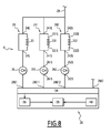
- the processing device 6 comprises at least two interferometers in parallel, for example three interferometers in parallel.
- the processing device 6 comprises a first interferometer 24, as described with regard to the figure 1 , a second interferometer 241 and a third interferometer 242.
- the processing device 6 also comprises a first detector 26, as described with reference to FIG. figure 1 a second detector 261 and a third detector 262.
- the second and third detectors 261, 262 are similar to the first detector 26.
- the second and third interferometers 241, 242 have a structure similar to the structure of the first interferometer 24.
- the second and third interferometers 241, 242 respectively comprise a second delay line 331 and a third delay line 332.
- the second delay line 331 has an input 331 E and an output 331 S.
- the third delay line 332 has an input 332E and an output 332S.
- the second delay line 331 is able to provide at its output 331 S a signal delayed by a time delay ⁇ * 1 with respect to a signal applied to its input 331 E.
- the third delay line 332 is capable of providing at its output 332S a signal delayed by a time delay ⁇ * 2 with respect to a signal applied to its input 332E.
- the lengths of the delay lines 33, 331, 332 are two by two different.
- the ratio between the largest of the delay ⁇ 0 of the delay line 33, the delay ⁇ * 1 of the second delay line 331 and the delay ⁇ * 2 of the third delay line 332, and the most small among these delays ⁇ 0 , ⁇ * 1 , ⁇ * 2 is greater than 2, preferably greater than 5, for example greater than 10.
- the second interferometer 241 comprises an input 241 E, connected to the demodulation fiber 29.
- the second interferometer 241 further comprises an output 241 S connected to an input 261 E of the second detector 261.
- the third interferometer 242 comprises an input 242E, connected to the demodulation fiber 29.
- the second interferometer 242 further comprises an output 242S connected to an input 262E of the second detector 262.
- the processing unit 28 has a second input 28E11 and a third input 28E12.
- the second input 28E11 is connected to an output 261 S of the second detector 261.
- the third input 28E12 is connected to an output 262S of the third detector 262.
- the sampled wave is conveyed by the demodulation fiber 29 from the laser source 9.
- the sampled wave is divided into three waves: a first wave taken, a second wave taken and a third wave taken.
- the first, the second and the third waves sampled are injected at the input 24E, 241E, 242E of the first, second and third interferometers 24, 241, 242 respectively.
- the user chooses a first, a second and a third positive integer number R 1 , R 2 , R 3 , at least one of which is non-zero, and inputs them via the input means 40.
- Each integer number R 1 , R 2 , R 3 is associated with a delay line 33, 331, 332.
- the operation of the treatment device 6 of the figure 8 is then similar to the operation of the treatment device of the figure 1 .
- the computer 38 calculates a reference signal, then a demodulation signal.
- the computer 38 then calculates the demodulated signal, which is equal to the successive product of the signal to be demodulated by each demodulation signal.
- At least one of the interferometers in parallel is in series with another interferometer.
- At least one of the interferometers in parallel comprises a nested interferometer.
- optical waves in such a demodulation process can generate delays for example between 10 ns and 500 ⁇ s. Such delays are capable of compensating for significant propagation distances of the waves from the transmitter 12 to the target 3, then from the target 3 to the receiver 16. For example, such delays are able to compensate for distances of spread between 3 m and 150 km. Such delays are more important than the delays experienced when using microwave waves.
- the electromagnetic wave emitted by the detection system 2 is a microwave wave.
- microwave electromagnetic wave is meant a wave whose frequency is between 0.1 GHz and 10 THz.
- the remote sensing device 4 is then a remote sensing device with radar technology (radio detection and ranging).
- the remote sensing device 4 then comprises components capable of generating, transmitting, receiving, interfering with or detecting microwave electromagnetic waves.
- the emission stage 7 is suitable for generating a microwave wave and for transmitting the microwave wave towards the target 3.
- the reception stage 8 is adapted to receive a microwave signal emitted by the target 3.
- the reception stage 8 is also able to generate an interference signal between the received wave and a portion of the wave generated. by the transmit stage 7.
- the receive stage 8 is further adapted to detect the interference signal to generate a signal to be demodulated.
- the processing device 6 is able to generate a demodulation signal from a portion of the microwave generated by the transmission stage 7, according to the method defined above.
- the processing device 6 comprises at least one interferometer comprising a first arm and a second arm.
- the second arm comprises a delay line, conventionally known, for inducing a predetermined delay in a microwave signal that passes through the delay line.
- the interferometric signal is for example obtained with an electronic mixture.
- the ratio between the largest delay ⁇ 0 , ⁇ 1 , ⁇ ' 1 , ⁇ * 1 , ⁇ * 2 introduced by a delay line 33, 33B, 330, 331 or 332 and the smallest of these delays ⁇ 0 , ⁇ 1 , ⁇ ' 1 , ⁇ * 1 , ⁇ * 2 is preferably greater than 5, preferably greater than 10, for example greater than 20.
Landscapes
- Engineering & Computer Science (AREA)
- Physics & Mathematics (AREA)
- General Physics & Mathematics (AREA)
- Radar, Positioning & Navigation (AREA)
- Remote Sensing (AREA)
- Computer Networks & Wireless Communication (AREA)
- Electromagnetism (AREA)
- Signal Processing (AREA)
- Instruments For Measurement Of Length By Optical Means (AREA)
- Optical Communication System (AREA)
Applications Claiming Priority (1)
| Application Number | Priority Date | Filing Date | Title |
|---|---|---|---|
| FR1400991A FR3020526B1 (fr) | 2014-04-28 | 2014-04-28 | Procede de generation de m signaux de demodulation |
Publications (2)
| Publication Number | Publication Date |
|---|---|
| EP2940522A1 true EP2940522A1 (de) | 2015-11-04 |
| EP2940522B1 EP2940522B1 (de) | 2020-12-02 |
Family
ID=51564689
Family Applications (1)
| Application Number | Title | Priority Date | Filing Date |
|---|---|---|---|
| EP15165519.8A Active EP2940522B1 (de) | 2014-04-28 | 2015-04-28 | Verfahren zur erzeugung von demodulationssignalen |
Country Status (3)
| Country | Link |
|---|---|
| US (1) | US9441949B2 (de) |
| EP (1) | EP2940522B1 (de) |
| FR (1) | FR3020526B1 (de) |
Families Citing this family (2)
| Publication number | Priority date | Publication date | Assignee | Title |
|---|---|---|---|---|
| GB201607875D0 (en) * | 2016-05-05 | 2016-06-22 | Qinetiq Ltd | Phase noise compensation system, and method |
| US11366206B2 (en) | 2019-03-18 | 2022-06-21 | Aeva, Inc. | Lidar apparatus with an optical amplifier in the return path |
Citations (4)
| Publication number | Priority date | Publication date | Assignee | Title |
|---|---|---|---|---|
| EP0849622A2 (de) * | 1996-12-19 | 1998-06-24 | Nortel Networks Corporation | Rein optisches Abtasten durch Modulation einer Impulsfolge |
| US20100085992A1 (en) * | 2008-10-08 | 2010-04-08 | George Rakuljic | Arbitrary Optical Waveform Generation Utilizing Optical Phase-Locked Loops |
| US20110080580A1 (en) * | 2006-03-10 | 2011-04-07 | Imra America, Inc. | Optical signal processing with modelocked lasers |
| US20130215919A1 (en) * | 2012-02-17 | 2013-08-22 | University Of Southern California | Wideband tunable laser line-width reduction |
Family Cites Families (4)
| Publication number | Priority date | Publication date | Assignee | Title |
|---|---|---|---|---|
| US5452086A (en) * | 1993-03-22 | 1995-09-19 | Litton Systems, Inc. | Interferometer amplitude modulation reduction circuit |
| EP1388739A1 (de) * | 2002-08-09 | 2004-02-11 | HILTI Aktiengesellschaft | Laserdistanzmessgerät mit Phasenlaufzeitmessung |
| GB0506209D0 (en) * | 2005-03-29 | 2005-05-04 | Qinetiq Ltd | Coherent frequency modulated continuous wave radar |
| JP4601500B2 (ja) * | 2005-07-06 | 2010-12-22 | 独立行政法人情報通信研究機構 | データ受信方法及び装置 |
-
2014
- 2014-04-28 FR FR1400991A patent/FR3020526B1/fr not_active Expired - Fee Related
-
2015
- 2015-04-28 US US14/698,658 patent/US9441949B2/en active Active
- 2015-04-28 EP EP15165519.8A patent/EP2940522B1/de active Active
Patent Citations (4)
| Publication number | Priority date | Publication date | Assignee | Title |
|---|---|---|---|---|
| EP0849622A2 (de) * | 1996-12-19 | 1998-06-24 | Nortel Networks Corporation | Rein optisches Abtasten durch Modulation einer Impulsfolge |
| US20110080580A1 (en) * | 2006-03-10 | 2011-04-07 | Imra America, Inc. | Optical signal processing with modelocked lasers |
| US20100085992A1 (en) * | 2008-10-08 | 2010-04-08 | George Rakuljic | Arbitrary Optical Waveform Generation Utilizing Optical Phase-Locked Loops |
| US20130215919A1 (en) * | 2012-02-17 | 2013-08-22 | University Of Southern California | Wideband tunable laser line-width reduction |
Non-Patent Citations (1)
| Title |
|---|
| ZEB W BARBER ET AL: "Linearization of ultra-broadband optical chirps for precision length metrology", CONFERENCE ON LASERS AND ELECTRO-OPTICS (CLEO) AND QUANTUM ELECTRONICS AND LASER SCIENCE CONFERENCE (QELS), 2010 : 16 - 21 MAY 2010, SAN JOSE, CA, USA, IEEE, PISCATAWAY, NJ , USA, 16 May 2010 (2010-05-16), pages 1 - 2, XP031700695, ISBN: 978-1-55752-890-2 * |
Also Published As
| Publication number | Publication date |
|---|---|
| US20150308811A1 (en) | 2015-10-29 |
| FR3020526A1 (fr) | 2015-10-30 |
| FR3020526B1 (fr) | 2016-05-27 |
| US9441949B2 (en) | 2016-09-13 |
| EP2940522B1 (de) | 2020-12-02 |
Similar Documents
| Publication | Publication Date | Title |
|---|---|---|
| EP2955542B1 (de) | Lidar-doppler zur relativen geschwindigkeitsmessung | |
| EP3504559B1 (de) | Verfahren zur verarbeitung eines signals aus kohärentem lidar und zugehöriges lidar-system | |
| EP0064908B1 (de) | Verfahren und Vorrichtung für das Messen der Temperatur eines Körpers mit Mikrowellen | |
| CN102636196B (zh) | 一种基于瑞利散射光谱相关系数的分布式扰动传感装置的解调方法 | |
| US10866319B2 (en) | Stray-light tolerant lidar measurement system and stray-light tolerant lidar measurement method | |
| EP3563178B1 (de) | Verfahren zur verarbeitung eines signals aus einem kohärenten lidar zur geräuschreduktion und zugehöriges lidar-system | |
| FR3043457A1 (fr) | Dispositif optoelectronique de mesure repartie par diffusion brillouin. | |
| EP3635354A2 (de) | Optoelektronische vorrichtung zur verteilten messung mittels optischer faser | |
| WO2002095475A1 (fr) | Procede et dispostif de mesure par imagerie confocale a chromatisme entendu | |
| EP3394560A1 (de) | Vorrichtung und verfahren zur messung der höhe in gegenwart von dünnschichten | |
| Wei et al. | Inversion probability enhancement of all-fiber CDWL by noise modeling and robust fitting | |
| EP0663590A1 (de) | Moduliertes Spektralellipsometer | |
| Liebermeister et al. | Terahertz multilayer thickness measurements: Comparison of optoelectronic time and frequency domain systems | |
| FR2468099A1 (fr) | Procede et appareil d'interferometrie laser a deux longueurs d'ondes | |
| EP2600141A1 (de) | Prüfgerät einer Oberfläche, und entsprechendes Verfahren | |
| EP2940522B1 (de) | Verfahren zur erzeugung von demodulationssignalen | |
| EP2724145A1 (de) | System und verfahren zur analyse durch bestimmung einer depolarisierenden oder dichromatischen merkmals eines objekts | |
| EP4004597B1 (de) | Verfahren für kohärente lidar-bildgebung und zugehöriger lidar | |
| Kameyama et al. | Feasibility study on 1.6 μm continuous-wave modulation laser absorption spectrometer system for measurement of global CO 2 concentration from a satellite | |
| EP2828635A1 (de) | System zur messung einer trennzone bei einem substrat | |
| CN112229501A (zh) | 一种基于ofdr的振动信号自动检测装置和方法 | |
| Totems et al. | Advanced signal processing methods for pulsed laser vibrometry | |
| Du et al. | Coherent high-spectral-resolution lidar for atmospheric temperature remote sensing with a convolutional neural network | |
| FR3118197A1 (fr) | Lidar cohérent à modulation de fréquence amélioré | |
| CN119880004B (zh) | 一种通过色散补偿提高光频域反射计测量分辨率的方法 |
Legal Events
| Date | Code | Title | Description |
|---|---|---|---|
| PUAI | Public reference made under article 153(3) epc to a published international application that has entered the european phase |
Free format text: ORIGINAL CODE: 0009012 |
|
| AK | Designated contracting states |
Kind code of ref document: A1 Designated state(s): AL AT BE BG CH CY CZ DE DK EE ES FI FR GB GR HR HU IE IS IT LI LT LU LV MC MK MT NL NO PL PT RO RS SE SI SK SM TR |
|
| AX | Request for extension of the european patent |
Extension state: BA ME |
|
| 17P | Request for examination filed |
Effective date: 20160422 |
|
| RBV | Designated contracting states (corrected) |
Designated state(s): AL AT BE BG CH CY CZ DE DK EE ES FI FR GB GR HR HU IE IS IT LI LT LU LV MC MK MT NL NO PL PT RO RS SE SI SK SM TR |
|
| STAA | Information on the status of an ep patent application or granted ep patent |
Free format text: STATUS: EXAMINATION IS IN PROGRESS |
|
| 17Q | First examination report despatched |
Effective date: 20190613 |
|
| 17Q | First examination report despatched |
Effective date: 20190619 |
|
| REG | Reference to a national code |
Ref country code: DE Ref legal event code: R079 Ref document number: 602015062799 Country of ref document: DE Free format text: PREVIOUS MAIN CLASS: G02F0001350000 Ipc: G01S0007491500 |
|
| GRAP | Despatch of communication of intention to grant a patent |
Free format text: ORIGINAL CODE: EPIDOSNIGR1 |
|
| STAA | Information on the status of an ep patent application or granted ep patent |
Free format text: STATUS: GRANT OF PATENT IS INTENDED |
|
| RIC1 | Information provided on ipc code assigned before grant |
Ipc: G01S 7/4915 20200101AFI20200604BHEP Ipc: G01S 17/34 20200101ALI20200604BHEP Ipc: G01S 13/34 20060101ALI20200604BHEP |
|
| INTG | Intention to grant announced |
Effective date: 20200707 |
|
| GRAS | Grant fee paid |
Free format text: ORIGINAL CODE: EPIDOSNIGR3 |
|
| GRAA | (expected) grant |
Free format text: ORIGINAL CODE: 0009210 |
|
| STAA | Information on the status of an ep patent application or granted ep patent |
Free format text: STATUS: THE PATENT HAS BEEN GRANTED |
|
| AK | Designated contracting states |
Kind code of ref document: B1 Designated state(s): AL AT BE BG CH CY CZ DE DK EE ES FI FR GB GR HR HU IE IS IT LI LT LU LV MC MK MT NL NO PL PT RO RS SE SI SK SM TR |
|
| REG | Reference to a national code |
Ref country code: GB Ref legal event code: FG4D Free format text: NOT ENGLISH |
|
| REG | Reference to a national code |
Ref country code: AT Ref legal event code: REF Ref document number: 1341534 Country of ref document: AT Kind code of ref document: T Effective date: 20201215 Ref country code: CH Ref legal event code: EP |
|
| REG | Reference to a national code |
Ref country code: IE Ref legal event code: FG4D Free format text: LANGUAGE OF EP DOCUMENT: FRENCH |
|
| REG | Reference to a national code |
Ref country code: DE Ref legal event code: R096 Ref document number: 602015062799 Country of ref document: DE |
|
| PG25 | Lapsed in a contracting state [announced via postgrant information from national office to epo] |
Ref country code: GR Free format text: LAPSE BECAUSE OF FAILURE TO SUBMIT A TRANSLATION OF THE DESCRIPTION OR TO PAY THE FEE WITHIN THE PRESCRIBED TIME-LIMIT Effective date: 20210303 Ref country code: FI Free format text: LAPSE BECAUSE OF FAILURE TO SUBMIT A TRANSLATION OF THE DESCRIPTION OR TO PAY THE FEE WITHIN THE PRESCRIBED TIME-LIMIT Effective date: 20201202 Ref country code: RS Free format text: LAPSE BECAUSE OF FAILURE TO SUBMIT A TRANSLATION OF THE DESCRIPTION OR TO PAY THE FEE WITHIN THE PRESCRIBED TIME-LIMIT Effective date: 20201202 Ref country code: NO Free format text: LAPSE BECAUSE OF FAILURE TO SUBMIT A TRANSLATION OF THE DESCRIPTION OR TO PAY THE FEE WITHIN THE PRESCRIBED TIME-LIMIT Effective date: 20210302 |
|
| REG | Reference to a national code |
Ref country code: NL Ref legal event code: MP Effective date: 20201202 |
|
| REG | Reference to a national code |
Ref country code: AT Ref legal event code: MK05 Ref document number: 1341534 Country of ref document: AT Kind code of ref document: T Effective date: 20201202 |
|
| PG25 | Lapsed in a contracting state [announced via postgrant information from national office to epo] |
Ref country code: BG Free format text: LAPSE BECAUSE OF FAILURE TO SUBMIT A TRANSLATION OF THE DESCRIPTION OR TO PAY THE FEE WITHIN THE PRESCRIBED TIME-LIMIT Effective date: 20210302 Ref country code: PL Free format text: LAPSE BECAUSE OF FAILURE TO SUBMIT A TRANSLATION OF THE DESCRIPTION OR TO PAY THE FEE WITHIN THE PRESCRIBED TIME-LIMIT Effective date: 20201202 Ref country code: LV Free format text: LAPSE BECAUSE OF FAILURE TO SUBMIT A TRANSLATION OF THE DESCRIPTION OR TO PAY THE FEE WITHIN THE PRESCRIBED TIME-LIMIT Effective date: 20201202 Ref country code: SE Free format text: LAPSE BECAUSE OF FAILURE TO SUBMIT A TRANSLATION OF THE DESCRIPTION OR TO PAY THE FEE WITHIN THE PRESCRIBED TIME-LIMIT Effective date: 20201202 |
|
| PG25 | Lapsed in a contracting state [announced via postgrant information from national office to epo] |
Ref country code: NL Free format text: LAPSE BECAUSE OF FAILURE TO SUBMIT A TRANSLATION OF THE DESCRIPTION OR TO PAY THE FEE WITHIN THE PRESCRIBED TIME-LIMIT Effective date: 20201202 Ref country code: HR Free format text: LAPSE BECAUSE OF FAILURE TO SUBMIT A TRANSLATION OF THE DESCRIPTION OR TO PAY THE FEE WITHIN THE PRESCRIBED TIME-LIMIT Effective date: 20201202 |
|
| REG | Reference to a national code |
Ref country code: LT Ref legal event code: MG9D |
|
| PG25 | Lapsed in a contracting state [announced via postgrant information from national office to epo] |
Ref country code: RO Free format text: LAPSE BECAUSE OF FAILURE TO SUBMIT A TRANSLATION OF THE DESCRIPTION OR TO PAY THE FEE WITHIN THE PRESCRIBED TIME-LIMIT Effective date: 20201202 Ref country code: PT Free format text: LAPSE BECAUSE OF FAILURE TO SUBMIT A TRANSLATION OF THE DESCRIPTION OR TO PAY THE FEE WITHIN THE PRESCRIBED TIME-LIMIT Effective date: 20210405 Ref country code: SK Free format text: LAPSE BECAUSE OF FAILURE TO SUBMIT A TRANSLATION OF THE DESCRIPTION OR TO PAY THE FEE WITHIN THE PRESCRIBED TIME-LIMIT Effective date: 20201202 Ref country code: LT Free format text: LAPSE BECAUSE OF FAILURE TO SUBMIT A TRANSLATION OF THE DESCRIPTION OR TO PAY THE FEE WITHIN THE PRESCRIBED TIME-LIMIT Effective date: 20201202 Ref country code: EE Free format text: LAPSE BECAUSE OF FAILURE TO SUBMIT A TRANSLATION OF THE DESCRIPTION OR TO PAY THE FEE WITHIN THE PRESCRIBED TIME-LIMIT Effective date: 20201202 Ref country code: CZ Free format text: LAPSE BECAUSE OF FAILURE TO SUBMIT A TRANSLATION OF THE DESCRIPTION OR TO PAY THE FEE WITHIN THE PRESCRIBED TIME-LIMIT Effective date: 20201202 Ref country code: SM Free format text: LAPSE BECAUSE OF FAILURE TO SUBMIT A TRANSLATION OF THE DESCRIPTION OR TO PAY THE FEE WITHIN THE PRESCRIBED TIME-LIMIT Effective date: 20201202 |
|
| PG25 | Lapsed in a contracting state [announced via postgrant information from national office to epo] |
Ref country code: AT Free format text: LAPSE BECAUSE OF FAILURE TO SUBMIT A TRANSLATION OF THE DESCRIPTION OR TO PAY THE FEE WITHIN THE PRESCRIBED TIME-LIMIT Effective date: 20201202 |
|
| REG | Reference to a national code |
Ref country code: DE Ref legal event code: R097 Ref document number: 602015062799 Country of ref document: DE |
|
| PG25 | Lapsed in a contracting state [announced via postgrant information from national office to epo] |
Ref country code: IS Free format text: LAPSE BECAUSE OF FAILURE TO SUBMIT A TRANSLATION OF THE DESCRIPTION OR TO PAY THE FEE WITHIN THE PRESCRIBED TIME-LIMIT Effective date: 20210402 |
|
| PLBE | No opposition filed within time limit |
Free format text: ORIGINAL CODE: 0009261 |
|
| STAA | Information on the status of an ep patent application or granted ep patent |
Free format text: STATUS: NO OPPOSITION FILED WITHIN TIME LIMIT |
|
| PG25 | Lapsed in a contracting state [announced via postgrant information from national office to epo] |
Ref country code: AL Free format text: LAPSE BECAUSE OF FAILURE TO SUBMIT A TRANSLATION OF THE DESCRIPTION OR TO PAY THE FEE WITHIN THE PRESCRIBED TIME-LIMIT Effective date: 20201202 Ref country code: IT Free format text: LAPSE BECAUSE OF FAILURE TO SUBMIT A TRANSLATION OF THE DESCRIPTION OR TO PAY THE FEE WITHIN THE PRESCRIBED TIME-LIMIT Effective date: 20201202 |
|
| 26N | No opposition filed |
Effective date: 20210903 |
|
| PG25 | Lapsed in a contracting state [announced via postgrant information from national office to epo] |
Ref country code: SI Free format text: LAPSE BECAUSE OF FAILURE TO SUBMIT A TRANSLATION OF THE DESCRIPTION OR TO PAY THE FEE WITHIN THE PRESCRIBED TIME-LIMIT Effective date: 20201202 Ref country code: DK Free format text: LAPSE BECAUSE OF FAILURE TO SUBMIT A TRANSLATION OF THE DESCRIPTION OR TO PAY THE FEE WITHIN THE PRESCRIBED TIME-LIMIT Effective date: 20201202 Ref country code: ES Free format text: LAPSE BECAUSE OF FAILURE TO SUBMIT A TRANSLATION OF THE DESCRIPTION OR TO PAY THE FEE WITHIN THE PRESCRIBED TIME-LIMIT Effective date: 20201202 Ref country code: MC Free format text: LAPSE BECAUSE OF FAILURE TO SUBMIT A TRANSLATION OF THE DESCRIPTION OR TO PAY THE FEE WITHIN THE PRESCRIBED TIME-LIMIT Effective date: 20201202 |
|
| PG25 | Lapsed in a contracting state [announced via postgrant information from national office to epo] |
Ref country code: LU Free format text: LAPSE BECAUSE OF NON-PAYMENT OF DUE FEES Effective date: 20210428 |
|
| REG | Reference to a national code |
Ref country code: BE Ref legal event code: MM Effective date: 20210430 |
|
| PG25 | Lapsed in a contracting state [announced via postgrant information from national office to epo] |
Ref country code: CH Free format text: LAPSE BECAUSE OF NON-PAYMENT OF DUE FEES Effective date: 20210430 Ref country code: LI Free format text: LAPSE BECAUSE OF NON-PAYMENT OF DUE FEES Effective date: 20210430 |
|
| PG25 | Lapsed in a contracting state [announced via postgrant information from national office to epo] |
Ref country code: IE Free format text: LAPSE BECAUSE OF NON-PAYMENT OF DUE FEES Effective date: 20210428 |
|
| PG25 | Lapsed in a contracting state [announced via postgrant information from national office to epo] |
Ref country code: IS Free format text: LAPSE BECAUSE OF FAILURE TO SUBMIT A TRANSLATION OF THE DESCRIPTION OR TO PAY THE FEE WITHIN THE PRESCRIBED TIME-LIMIT Effective date: 20210402 |
|
| PG25 | Lapsed in a contracting state [announced via postgrant information from national office to epo] |
Ref country code: BE Free format text: LAPSE BECAUSE OF NON-PAYMENT OF DUE FEES Effective date: 20210430 |
|
| PG25 | Lapsed in a contracting state [announced via postgrant information from national office to epo] |
Ref country code: HU Free format text: LAPSE BECAUSE OF FAILURE TO SUBMIT A TRANSLATION OF THE DESCRIPTION OR TO PAY THE FEE WITHIN THE PRESCRIBED TIME-LIMIT; INVALID AB INITIO Effective date: 20150428 |
|
| P01 | Opt-out of the competence of the unified patent court (upc) registered |
Effective date: 20230425 |
|
| PG25 | Lapsed in a contracting state [announced via postgrant information from national office to epo] |
Ref country code: CY Free format text: LAPSE BECAUSE OF FAILURE TO SUBMIT A TRANSLATION OF THE DESCRIPTION OR TO PAY THE FEE WITHIN THE PRESCRIBED TIME-LIMIT Effective date: 20201202 |
|
| PG25 | Lapsed in a contracting state [announced via postgrant information from national office to epo] |
Ref country code: MK Free format text: LAPSE BECAUSE OF FAILURE TO SUBMIT A TRANSLATION OF THE DESCRIPTION OR TO PAY THE FEE WITHIN THE PRESCRIBED TIME-LIMIT Effective date: 20201202 |
|
| PG25 | Lapsed in a contracting state [announced via postgrant information from national office to epo] |
Ref country code: MT Free format text: LAPSE BECAUSE OF FAILURE TO SUBMIT A TRANSLATION OF THE DESCRIPTION OR TO PAY THE FEE WITHIN THE PRESCRIBED TIME-LIMIT Effective date: 20201202 |
|
| PGFP | Annual fee paid to national office [announced via postgrant information from national office to epo] |
Ref country code: DE Payment date: 20250411 Year of fee payment: 11 |
|
| PGFP | Annual fee paid to national office [announced via postgrant information from national office to epo] |
Ref country code: GB Payment date: 20250417 Year of fee payment: 11 |
|
| PGFP | Annual fee paid to national office [announced via postgrant information from national office to epo] |
Ref country code: FR Payment date: 20250429 Year of fee payment: 11 |
|
| PG25 | Lapsed in a contracting state [announced via postgrant information from national office to epo] |
Ref country code: TR Free format text: LAPSE BECAUSE OF FAILURE TO SUBMIT A TRANSLATION OF THE DESCRIPTION OR TO PAY THE FEE WITHIN THE PRESCRIBED TIME-LIMIT Effective date: 20201202 |