EP2940552A1 - Dispositif d'affichage réglable - Google Patents
Dispositif d'affichage réglable Download PDFInfo
- Publication number
- EP2940552A1 EP2940552A1 EP14197145.7A EP14197145A EP2940552A1 EP 2940552 A1 EP2940552 A1 EP 2940552A1 EP 14197145 A EP14197145 A EP 14197145A EP 2940552 A1 EP2940552 A1 EP 2940552A1
- Authority
- EP
- European Patent Office
- Prior art keywords
- display device
- angle block
- links
- angle
- driving system
- Prior art date
- Legal status (The legal status is an assumption and is not a legal conclusion. Google has not performed a legal analysis and makes no representation as to the accuracy of the status listed.)
- Granted
Links
Images



Classifications
-
- G—PHYSICS
- G09—EDUCATION; CRYPTOGRAPHY; DISPLAY; ADVERTISING; SEALS
- G09G—ARRANGEMENTS OR CIRCUITS FOR CONTROL OF INDICATING DEVICES USING STATIC MEANS TO PRESENT VARIABLE INFORMATION
- G09G3/00—Control arrangements or circuits, of interest only in connection with visual indicators other than cathode-ray tubes
- G09G3/03—Control arrangements or circuits, of interest only in connection with visual indicators other than cathode-ray tubes specially adapted for displays having non-planar surfaces, e.g. curved displays
-
- G—PHYSICS
- G02—OPTICS
- G02F—OPTICAL DEVICES OR ARRANGEMENTS FOR THE CONTROL OF LIGHT BY MODIFICATION OF THE OPTICAL PROPERTIES OF THE MEDIA OF THE ELEMENTS INVOLVED THEREIN; NON-LINEAR OPTICS; FREQUENCY-CHANGING OF LIGHT; OPTICAL LOGIC ELEMENTS; OPTICAL ANALOGUE/DIGITAL CONVERTERS
- G02F1/00—Devices or arrangements for the control of the intensity, colour, phase, polarisation or direction of light arriving from an independent light source, e.g. switching, gating or modulating; Non-linear optics
- G02F1/01—Devices or arrangements for the control of the intensity, colour, phase, polarisation or direction of light arriving from an independent light source, e.g. switching, gating or modulating; Non-linear optics for the control of the intensity, phase, polarisation or colour
- G02F1/13—Devices or arrangements for the control of the intensity, colour, phase, polarisation or direction of light arriving from an independent light source, e.g. switching, gating or modulating; Non-linear optics for the control of the intensity, phase, polarisation or colour based on liquid crystals, e.g. single liquid crystal display cells
- G02F1/133—Constructional arrangements; Operation of liquid crystal cells; Circuit arrangements
- G02F1/1333—Constructional arrangements; Manufacturing methods
- G02F1/133305—Flexible substrates, e.g. plastics, organic film
-
- G—PHYSICS
- G02—OPTICS
- G02F—OPTICAL DEVICES OR ARRANGEMENTS FOR THE CONTROL OF LIGHT BY MODIFICATION OF THE OPTICAL PROPERTIES OF THE MEDIA OF THE ELEMENTS INVOLVED THEREIN; NON-LINEAR OPTICS; FREQUENCY-CHANGING OF LIGHT; OPTICAL LOGIC ELEMENTS; OPTICAL ANALOGUE/DIGITAL CONVERTERS
- G02F1/00—Devices or arrangements for the control of the intensity, colour, phase, polarisation or direction of light arriving from an independent light source, e.g. switching, gating or modulating; Non-linear optics
- G02F1/01—Devices or arrangements for the control of the intensity, colour, phase, polarisation or direction of light arriving from an independent light source, e.g. switching, gating or modulating; Non-linear optics for the control of the intensity, phase, polarisation or colour
- G02F1/13—Devices or arrangements for the control of the intensity, colour, phase, polarisation or direction of light arriving from an independent light source, e.g. switching, gating or modulating; Non-linear optics for the control of the intensity, phase, polarisation or colour based on liquid crystals, e.g. single liquid crystal display cells
- G02F1/133—Constructional arrangements; Operation of liquid crystal cells; Circuit arrangements
- G02F1/1333—Constructional arrangements; Manufacturing methods
- G02F1/133308—Support structures for LCD panels, e.g. frames or bezels
-
- G—PHYSICS
- G06—COMPUTING OR CALCULATING; COUNTING
- G06F—ELECTRIC DIGITAL DATA PROCESSING
- G06F1/00—Details not covered by groups G06F3/00 - G06F13/00 and G06F21/00
- G06F1/16—Constructional details or arrangements
- G06F1/1601—Constructional details related to the housing of computer displays, e.g. of CRT monitors, of flat displays
-
- G—PHYSICS
- G06—COMPUTING OR CALCULATING; COUNTING
- G06F—ELECTRIC DIGITAL DATA PROCESSING
- G06F1/00—Details not covered by groups G06F3/00 - G06F13/00 and G06F21/00
- G06F1/16—Constructional details or arrangements
- G06F1/1613—Constructional details or arrangements for portable computers
-
- G—PHYSICS
- G06—COMPUTING OR CALCULATING; COUNTING
- G06F—ELECTRIC DIGITAL DATA PROCESSING
- G06F1/00—Details not covered by groups G06F3/00 - G06F13/00 and G06F21/00
- G06F1/16—Constructional details or arrangements
- G06F1/1613—Constructional details or arrangements for portable computers
- G06F1/1626—Constructional details or arrangements for portable computers with a single-body enclosure integrating a flat display, e.g. Personal Digital Assistants [PDAs]
-
- G—PHYSICS
- G06—COMPUTING OR CALCULATING; COUNTING
- G06F—ELECTRIC DIGITAL DATA PROCESSING
- G06F1/00—Details not covered by groups G06F3/00 - G06F13/00 and G06F21/00
- G06F1/16—Constructional details or arrangements
- G06F1/1613—Constructional details or arrangements for portable computers
- G06F1/1633—Constructional details or arrangements of portable computers not specific to the type of enclosures covered by groups G06F1/1615 - G06F1/1626
- G06F1/1637—Details related to the display arrangement, including those related to the mounting of the display in the housing
- G06F1/1652—Details related to the display arrangement, including those related to the mounting of the display in the housing the display being flexible, e.g. mimicking a sheet of paper, or rollable
-
- G—PHYSICS
- G09—EDUCATION; CRYPTOGRAPHY; DISPLAY; ADVERTISING; SEALS
- G09F—DISPLAYING; ADVERTISING; SIGNS; LABELS OR NAME-PLATES; SEALS
- G09F9/00—Indicating arrangements for variable information in which the information is built-up on a support by selection or combination of individual elements
- G09F9/30—Indicating arrangements for variable information in which the information is built-up on a support by selection or combination of individual elements in which the desired character or characters are formed by combining individual elements
- G09F9/301—Indicating arrangements for variable information in which the information is built-up on a support by selection or combination of individual elements in which the desired character or characters are formed by combining individual elements flexible foldable or roll-able electronic displays, e.g. thin LCD, OLED
-
- G—PHYSICS
- G09—EDUCATION; CRYPTOGRAPHY; DISPLAY; ADVERTISING; SEALS
- G09G—ARRANGEMENTS OR CIRCUITS FOR CONTROL OF INDICATING DEVICES USING STATIC MEANS TO PRESENT VARIABLE INFORMATION
- G09G3/00—Control arrangements or circuits, of interest only in connection with visual indicators other than cathode-ray tubes
- G09G3/20—Control arrangements or circuits, of interest only in connection with visual indicators other than cathode-ray tubes for presentation of an assembly of a number of characters, e.g. a page, by composing the assembly by combination of individual elements arranged in a matrix no fixed position being assigned to or needed to be assigned to the individual characters or partial characters
- G09G3/22—Control arrangements or circuits, of interest only in connection with visual indicators other than cathode-ray tubes for presentation of an assembly of a number of characters, e.g. a page, by composing the assembly by combination of individual elements arranged in a matrix no fixed position being assigned to or needed to be assigned to the individual characters or partial characters using controlled light sources
- G09G3/30—Control arrangements or circuits, of interest only in connection with visual indicators other than cathode-ray tubes for presentation of an assembly of a number of characters, e.g. a page, by composing the assembly by combination of individual elements arranged in a matrix no fixed position being assigned to or needed to be assigned to the individual characters or partial characters using controlled light sources using electroluminescent panels
- G09G3/32—Control arrangements or circuits, of interest only in connection with visual indicators other than cathode-ray tubes for presentation of an assembly of a number of characters, e.g. a page, by composing the assembly by combination of individual elements arranged in a matrix no fixed position being assigned to or needed to be assigned to the individual characters or partial characters using controlled light sources using electroluminescent panels semiconductive, e.g. using light-emitting diodes [LED]
- G09G3/3208—Control arrangements or circuits, of interest only in connection with visual indicators other than cathode-ray tubes for presentation of an assembly of a number of characters, e.g. a page, by composing the assembly by combination of individual elements arranged in a matrix no fixed position being assigned to or needed to be assigned to the individual characters or partial characters using controlled light sources using electroluminescent panels semiconductive, e.g. using light-emitting diodes [LED] organic, e.g. using organic light-emitting diodes [OLED]
-
- H—ELECTRICITY
- H04—ELECTRIC COMMUNICATION TECHNIQUE
- H04N—PICTORIAL COMMUNICATION, e.g. TELEVISION
- H04N5/00—Details of television systems
- H04N5/64—Constructional details of receivers, e.g. cabinets or dust covers
-
- G—PHYSICS
- G02—OPTICS
- G02F—OPTICAL DEVICES OR ARRANGEMENTS FOR THE CONTROL OF LIGHT BY MODIFICATION OF THE OPTICAL PROPERTIES OF THE MEDIA OF THE ELEMENTS INVOLVED THEREIN; NON-LINEAR OPTICS; FREQUENCY-CHANGING OF LIGHT; OPTICAL LOGIC ELEMENTS; OPTICAL ANALOGUE/DIGITAL CONVERTERS
- G02F1/00—Devices or arrangements for the control of the intensity, colour, phase, polarisation or direction of light arriving from an independent light source, e.g. switching, gating or modulating; Non-linear optics
- G02F1/01—Devices or arrangements for the control of the intensity, colour, phase, polarisation or direction of light arriving from an independent light source, e.g. switching, gating or modulating; Non-linear optics for the control of the intensity, phase, polarisation or colour
- G02F1/13—Devices or arrangements for the control of the intensity, colour, phase, polarisation or direction of light arriving from an independent light source, e.g. switching, gating or modulating; Non-linear optics for the control of the intensity, phase, polarisation or colour based on liquid crystals, e.g. single liquid crystal display cells
- G02F1/133—Constructional arrangements; Operation of liquid crystal cells; Circuit arrangements
- G02F1/1333—Constructional arrangements; Manufacturing methods
- G02F1/133308—Support structures for LCD panels, e.g. frames or bezels
- G02F1/133322—Mechanical guidance or alignment of LCD panel support components
Definitions
- the present disclosure relates to an adjustable or variable display device that is able to be used in a flat mode and a curved mode, and more particularly, to an adjustable or variable display device with improved flatness.
- FPD flat panel display
- the flat panel display devices include, for example, liquid crystal display (LCD) devices, plasma display panel (PDP) devices, field emission display (FED) devices, electroluminescence display (ELD) devices, and organic electroluminescent display (OLED) devices.
- LCD liquid crystal display
- PDP plasma display panel
- FED field emission display
- ELD electroluminescence display
- OLED organic electroluminescent display
- the flat panel display devices generally have a thin profile, light weight, and low power consumption; and have been rapidly replacing cathode ray tubes (CRT).
- CTR cathode ray tubes
- curved display devices have emerged as a new generation display device because the curved display devices enable a user to be further immersed in the content, to watch realistic images, and to feel more comfortable.
- variable display devices having the advantages of the flat panel display devices with wide viewing angles and curved display devices with increased immersion and comfort properties have been pursued and researched.
- variable display devices are implemented in both a flat mode to provide wide viewing area, and in a curved mode to improve immersion while watching.
- the present invention is directed to a variable display device that substantially obviates one or more of the problems due to limitations and disadvantages of the related art.
- An advantage of the present invention is to provide a variable display device that is able to be implemented in both a flat mode and a curved mode.
- Another advantage of the present invention is to provide a variable display device that has an accurate curvature when it is implemented in a curved mode, minimizes vibrations and noises when it is changed between the flat mode and the curved mode, and has a relatively light weight and thin profile.
- Another advantage of the present invention is to provide a variable display device that improves flatness when it is implemented in the flat mode.
- the display device further comprises a display panel, wherein changing the curvature of the display device changes a curvature of the display panel.
- the display panel includes an organic light emitting diode (OLED) device.
- the angle block modules comprise links and angle blocks.
- the display device further comprises a shaft bearing connecting links of adjacent angle blocks.
- the first and the second angle block modules comprise: multiple block units arranged in a row, each block unit having an angle block and links at two sides of the angle block; and a shaft bearing connecting links of each block unit to links of an adjacent block unit, wherein a first angle block module is at one side of the driving system and a second angle block module is at an opposite side of the driving system.
- the angle blocks of the multiple block units have a rectangular shape with two long sides and two short sides, the long sides have a length corresponding to the length of the links, the short sides are perpendicular to the long sides and are shorter than the long sides, wherein the angle blocks have a protrusion at one of the short sides, and a raised part at the other one of the short sides, and wherein a protrusion of one angle block is oriented in a raised part of an adjacent angle block.
- the driving system comprises: a driver generating motion; and a driving component delivering the motion to the first and the second angle block modules.
- the driver includes a motor.
- the display device further comprises a flatness controlling unit connected to the first and the second angle block modules to flatten the display device.
- a flatness controlling unit connected to the first and the second angle block modules to flatten the display device.
- each half of the rear of the display device is a top portion or a bottom portion.
- the driving system is at a center portion of the rear of the display device between the first and the second angle block modules.
- a display device capable of being adjusted between flat and curved comprises: an adjusting system at a rear of the display device including: first and second angle block modules capable of being moved, wherein moving the angle block modules changes a curvature of the display device; and a driving system coupled to the angle block module, wherein the driving system moves the angle block modules.
- the first and the second angle block modules comprise: multiple block units arranged in a row, each block unit having an angle block and links at two sides of the angle block; and a shaft bearing connecting links of each block unit to links of an adjacent block unit, wherein the first and the second angle block modules are at a side of the driving system.
- the driving system comprises: a driver generating motion; and a driver component delivering the motion to the first and the second angle block modules.
- the driver includes a motor.
- the driving system is at a center portion of the rear of the display device.
- a display device capable of being adjusted between flat and curved comprises: an angle block module at a rear of the display device capable of being moved, wherein moving (or, a movement of) the angle block module changes a curvature of the display device; and a driving system to move the angle block module.
- the angle block module comprises: multiple block units arranged in a row, each block unit having an angle block and links at two sides of the angle block; and a shaft bearing connecting links of each block unit to links of an adjacent block unit, wherein the angle block module is at a side of the driving system.
- the angle blocks of the multiple block units have a rectangular shape with two long sides and two short sides, the long sides have a length corresponding to the length of the links, the short sides are perpendicular to the long sides and are shorter than the long sides, wherein the angle blocks have a protrusion at one of the short sides, and a raised part at the other one of the short sides, and wherein a protrusion of one angle block is oriented in a raised part of an adjacent angle block.
- the driving system comprises: a driver generating motion; and a driver component delivering the motion to the first and the second angle block modules.
- the driver includes a motor.
- the driving system is at a center portion of the rear of the display device.
- a flatness controlling unit of a display device comprises: a driving system coupled to the display device; an angle block module coupled to the driving system having a flatness controlling groove; a wire guided by the flatness controlling groove having a first end connected to the driving system and a second end connected to the angle block module; a tension adjusting part including a portion of the wire and a spring connected to the portion of the wire.
- the spring is lengthened, and the wire is tightened along a rear surface of the display device applying force from an end of the display device toward a center of the display device flattening a central portion of the display device.
- a tension of the wire is smaller than a force applied through the angle block module such that the display device is curved.
- the spring is untensioned and the wire prevented from applying force from an end of the display device toward a center of the display device.
- the tension adjusting part applies a force from an end of the display device toward a center of the display device flattening the display device.
- the flatness controlling unit further comprises a tightening apparatus for adjusting tension of the wire.
- a driving system to curve and flatten a display device comprises: a driver generating motion in a first and a second direction; a driver component connected to the driver transferring the motion to an angle block module; block units arranged in a row in the angle block module and positioned at a rear of the display device; a shaft bearing connecting a first block unit to a second block unit; wherein the motion generates movement of the block units to move a portion of the display device with respect to a direction normal to a center of the display device.
- each block unit includes an angle block and links; and first links of the first block unit and second links of the second block unit are connected to each other with the shaft bearing oriented perpendicular to a length of the links.
- the shaft bearing is inserted into bearing holes at a first end of the first links and a second end of the second links.
- the angle blocks have a rectangular shape with two long sides and two short sides, wherein the long sides have a length corresponding to a length of the links, wherein the short sides are perpendicular to the long sides and are shorter than the long sides, and wherein a first short side includes a protrusion.
- a second short side includes a raised part, wherein the protrusion is thinner and narrower than each angle block, wherein the protrusion has a surface inclined toward a back cover of the display panel, and wherein a protrusion of a first angle block is disposed on a raised part of a second angle block.
- the motion in the first direction generates movement of the block units in a direction perpendicular to a front surface of the display device to force the display device to curve.
- the motion in the second direction generates movement of the block units in a direction perpendicular to a front surface of the display device to force the display device to flatten.
- the driver includes a motor.
- a method of adjusting a display device between flat and curved the display device having an angle block module at a rear of the display device, the angle block module capable of being moved, and a driving system to move the angle block module, the method comprising the step of: activating the driving system to move the angle block module to adjust a curvature of the display device.
- movement of the angle block module causes movement of a portion of the display device in a direction normal to a center of the display device.
- the movement of the portion of the display device causes the display device to curve.
- the movement of the portion of the display device causes the display device to flatten.
- adjusting the curvature of the display device comprises: driving a driver in the driving system to create motion and delivering the motion to first links of the angle block module, the motion moving the first links relative to the driver; by movement of the first links, contradicting a stationary force of angle blocks that are fixed to the rear of the display device and connected to the first links; and moving a shaft bearing connecting the first links to second links in a direction normal to the rear of the display device to move short sides of the angle blocks at an angle relative to the rear of the display device to move the display device with respect to the normal direction.
- moving the first links away from the driver increases the curvature of the display device and moving the first links closer to the driver decreases the curvature of the display device.
- FIG. 1A and FIG. 1B are perspective views schematically illustrating a variable display device according to an exemplary embodiment of the present invention
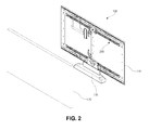
- FIG. 2 is a perspective view schematically illustrating a rear side of a variable display device according to an exemplary embodiment of the present invention.
- the variable display device 100 includes a display panel module 110, an external case 120, and a support 130.
- the display panel module 110 displays images
- the external case 120 accommodates the display panel module 110.
- the support 130 is connected to a lower part or a rear part of the external case 120 for mounting the variable display device, and is rested on a desk, fixed to a surface of a wall, or mounted by any other of many techniques and positioned for viewing.
- the display panel module 110 may include a display panel, which may be one of a liquid crystal display (LCD) device, a plasma display panel (PDP) device, a field emission display (FED) device, an electroluminescence display (ELD) device, and an organic light emitting diode (OLED) device.
- a display panel which may be one of a liquid crystal display (LCD) device, a plasma display panel (PDP) device, a field emission display (FED) device, an electroluminescence display (ELD) device, and an organic light emitting diode (OLED) device.
- the display panel module 110 may include an OLED device, which is flexible and displays images without a problem even when it is curved.
- OLED devices are self-luminescent, the OELD devices do not require a backlight unit and have a thin profile and light weight as compared with LCD devices, which are non-emissive.
- the OLED devices have better viewing angles and contrast ratio than comparable LCD devices and have lower power consumption.
- the OLED devices are driven by low voltage of direct current (DC), and have relatively fast response time. Since the OLED devices include solid components, the OLED devices are resistant to outer impacts and are stable under temperatures within a wide range.
- the display panel which is an OLED device, includes a first substrate and a second substrate facing each other.
- the first and second substrates are spaced apart from and attached to each other by a protection layer having an adhesive property.
- a driving thin film transistor is formed in each pixel region on the first substrate, and a first electrode, an organic light-emitting layer, and a second electrode are sequentially formed on the first substrate.
- the first electrode is formed in each pixel region and connected to the driving thin film transistor. With applied voltage, the organic light-emitting layer emits light.
- the organic light-emitting layer may be formed in each pixel region.
- the second electrode may be formed all over the first substrate and covers the organic light-emitting layer.
- the organic light-emitting layer may emit red, green, or blue light and may be generally formed by patterning an organic material emitting red, green, or blue light in each pixel region. Thus, red, green, and blue pixel regions are sequentially arranged.
- the first and second electrodes and the organic light-emitting layer constitute a light-emitting diode.
- the display panel module 110 may include the first electrode as an anode and the second electrode as a cathode.
- the display panel is modularized with a backcover and may include a protective cover window to form the display panel module 110.
- the backcover covers a rear surface and part of side surfaces of the display panel, and the front side of the backcover is opened such that an image displayed by the display panel is shown to the outside.
- the cover window may be assembled at the front side of the backcover to protect the display panel.
- variable display device 100 including the display panel module 110 has relatively wide viewing area and provides many viewers with the images displayed by the display panel module 110.
- variable display device 100 when the display panel module 110 is driven in a curved mode, the variable display device 100 enables a viewer to be further immersed in watching, to watch realistic images and to feel more comfortable.
- variable display device 100 is variably driven in the flat mode and the curved mode, a user can selectively use the variable display device 100 in the flat mode or curved mode as occasion demands.
- variable display device 100 is variably oriented in the flat mode or the curved mode by a backcover system 200, which is installed at a rear surface of the display panel module 110, as illustrated in FIG. 2 . This will be described in more detail with reference to accompanying drawings.
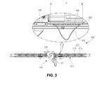
- FIG. 3 is a view schematically illustrating a backcover system according to an exemplary embodiment of the present invention.
- FIG. 4 is an exploded perspective view schematically illustrating an angle block module according to an exemplary embodiment of the present invention.
- the backcover system 200 is installed at a rear surface of the backcover of the display panel module 110 of FIG. 2 , and the backcover system 200 includes an angle block module 210, a driving system 220, and a flatness controlling unit 300.
- the driving system 220 supplies power to the angle block module 210.
- An angle block module is a mechanical structure attached to the display device and capable of being moved to adjust the curvature of the display device.
- a plurality of block units 211 are arranged in a row in the angle block module 210.
- Each block unit 211 includes an angle block 213 and links 215.
- the links 215 convert rotary motion delivered by the driving system 220 into rectilinear motion.
- a shaft bearing 217 of FIG. 4 is disposed between adjacent block units 211.
- the shaft bearing 217 connects the links 215 of each block unit 211 and also connects the links 215 of adjacent block units 211.
- the shaft bearing 217 raises and lowers edges of the angle blocks 213 contacting each other.
- the driving system 220 includes a motor 221 as a driver generating rotatory power and a gear 223 as a driver component delivering rotary motion of the motor 221 into the links 215.
- the driving system may include other drivers or systems that may generate movement or power such as those using hydraulic, pneumatic, piston, actuator, servos, electromagnetic, and the like.
- the angle block module 210 is disposed at each of both left and right sides with the driving system 220 at the center of a width of the display module 110 of FIG. 2 .
- the plurality of block units 211a and 211b are arranged in a row in the angle block module 210, and each block unit 211a and 211b includes the angle block 213a and 213b and the links 215a and 215b, which are disposed at both sides of the angle block 213a and 213b.
- the first angle block 213a is disposed between the first links 215a.
- the second block unit 211b is disposed next to the first block unit 211a, and in the second block unit 211b, the second angle block 213b is disposed between the couple of second links 215b, which are connected to the first links 215a.
- the shaft bearing 217 is disposed between the first and second block units 211a and 211b, i.e., between the first and second angle blocks 213a and 213b and is perpendicular to a length direction of the first and second links 215a and 215b. Ends of the first and second links 215a and 215b are connected to each other through the shaft bearing 217.
- each of the first links 215a has a first end and a second end
- each of the second links 215b has a third end and a fourth end.
- the bearing holes 219 are formed at the first and second ends of the first links 215a and the third and fourth ends of the second links 215b, respectively.
- the shaft bearing 217 is inserted into the bearing holes 219 at the first ends of the first links 215a and the third ends of the second links 215b corresponding to each other, and the first ends of the first links 215a and the third ends of the second links 215b are connected to each other through the shaft bearing 217.
- each first link 215a has an outer surface on the same plane as an outer surface of a portion of the first link 215a excluding the first and second ends and has a thinner thickness than the portion of the first link 215a.
- the third end of each second link 215b has an inner surface on the same plane as an inner surface of a portion of the second link 215b excluding the third and fourth ends and has a thinner thickness than the portion of the second link 215b.
- the first end of the first link 215a and the third end of the second link 215b, which contact each other, have a structure of engaging each other.
- first end of the first link 215a extends from an outer side of the portion of the first link 215a
- third end of the second link 215b extends from an inner side of the portion of the second link 215b.
- the first end of the first link 215a and the third end of the second link 215b engage each other, and the first and second link 215a and 215b are installed in a line with each other, so that the angle block module 210 may be prevented from increasing in volume.
- each first link 215a has an inner surface on the same plane as an inner surface of the portion of the first link 215a excluding the first and second ends and has a thinner thickness than the portion of the first link 215a.
- the fourth end of each second link 215b has an outer surface on the same plane as an outer surface of the portion of the second link 215b excluding the third and fourth ends and has a thinner thickness than the portion of the second link 215b.
- Each of the first and second angle blocks 213a and 213b has a substantially rectangular shape with two long sides and two short sides.
- the long sides have a length corresponding to the length of the first and second links 215a and 215b.
- the short sides are perpendicular to the long sides and are shorter than the long sides.
- a protrusion 212 is formed at one of the short sides of each angle block 213a and 213b.
- the protrusion 212 is thinner and narrower than each angle block 213a and 213b.
- the protrusion 212 is formed to be inclined toward the backcover of the display panel module 110 of FIG. 2 with a predetermined angle from one end of the protrusion 212 at the first short side to the other end of the protrusion 212.
- first short sides the short sides of the angle blocks 213a and 213b, where the protrusions 212 are formed
- second short sides the short sides of the angle blocks 213a and 213b opposite to the first short sides
- a raised part 214 is formed at the second side of each angle block 213a and 213b.
- the protrusion 212 of the first angle block 213a is put on and is combined with the raised part 214 of the second angle block 213b.
- the raised part 214 has a stepped shape corresponding to the width and thickness of the protrusion 212.
- Raised part sides 214a are formed at both sides of the raised part 214.
- a plurality of holes may be formed in each of the angle blocks 213a and 213b to decrease the weight of the angle block module 210.
- the variable display device 100 of FIG. 2 it is possible to provide the variable display device 100 of FIG. 2 with a lighter weight.
- the shaft bearing 217 between the first and second block units 211a and 211b adjacent to each other connects the first ends of the first links 215a and the third ends of the second links 215b.
- the shaft bearing 217 is disposed over the raised part 214, and more particularly, over the raised part 214 of the second angle block 213b, and both ends of the shaft bearing 217 are inserted into and guided by holes 214b, which are formed at the raised part sides 214a along a length direction of the raised part sides 214a, respectively.
- both ends of the shaft bearing 217 are inserted into the holes 214b formed at the raised part sides 214a and inserted into the bearing holes 219 of the first and second links 215a and 215b, respectively.
- a roller 217a is installed to the shaft bearing 217.
- the shaft bearing 217 guides the protrusion 212 of the first angle block 213a such that the protrusion 212 of the first angle block 213a may be inserted into the raised part 214 of the second angle block 213b adjacent to the protrusion 212 of the first angle block 213a. Additionally, the shaft bearing 217 receives driving power due to the rectilinear motion transferred to the first and second links 215a and 215b and vertically lifts the edges of the first and second angle blocks 213a and 213b which are adjacent to each other and in which the protrusion 212 is inserted into the raised part 214.
- a groove 214c may be further formed in the raised part 214 to guide the roller 217a.
- a stopping part 214d may be formed at an edge of the raised part 214, and the shaft bearing 217 and the roller 217a may be prevented from getting out of the raised part 214.
- the backcover system 200 may have a curved shape or a flat shape overall as the angle block module 210 may be driven such that the edges of the first and second angle blocks 213a and 213b may be raised or lowered with the driving system 220 at the center.
- variable display device 100 of FIG. 2 may be selectively varied and used in the flat mode and the curved mode by the backcover system 200, which is installed at the rear surface of the backcover of the display panel module 110 of FIG. 2 .
- the flatness controlling unit 300 is installed at each angle block module 210, which is disposed at each of both sides of the driving system 220.
- the flatness controlling unit 300 improves the flatness of the variable display device 100 of FIG. 2 when the variable display device 100 of FIG. 2 is driven in the flat mode.
- the flatness controlling unit 300 includes a wire 310.
- the wire 310 is guided by and disposed in a flatness controlling groove 320 shown in FIG. 5F , which is formed at a side or at each of both sides of the angle blocks 213 of the angle block module 210 along a length direction of the angle blocks 213.
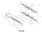
- the flatness controlling unit 300 includes a tension adjusting part A, which is composed of a portion of the wire 310 and a spring 330 that is connected to the portion of the wire 310, as illustrated in FIGs. 3 and 5G .
- one end of the spring 330 is connected to a first side of the portion of the wire 310 and the other end of the spring 330 is connected to a second side of the portion of the wire 310.
- a length of the spring 330 is shorter than a length of the portion of the wire 310.
- the wire 310 installed in the angle block module 210 is disposed at each of both sides of the driving system 220 and has a length corresponding to a length of the rear surface of the display panel module 110 of FIG. 2 in a curved mode.
- variable display device 100 of FIG. 2 when it is driven as the flat mode, the flatness of the variable display device 100 of FIG. 2 is further improved by the flatness controlling unit 300.
- variable display device 100 of FIG. 2 a process of changing the variable display device 100 of FIG. 2 from the flat mode to the curved mode using the backcover system 200 will be described in detail with reference to drawings.
- FIGs. 5A to 5G are views schematically illustrating a process of changing a variable display device according to an exemplary embodiment from a flat mode into a curved mode.
- the angle block module will be mainly described.
- the backcover system 200 is installed at the rear surface of the backcover of the display panel module 110 of FIG. 2 along a width of the backcover.
- the angle block module 210 of the backcover system 200 of FIG. 4 is disposed at each of both sides of the display panel module 110 with the driving system 220 in the center.
- the block units 211a, 211b, and 211c of the angle block module 210 are fixed to the backcover of the display panel module 110 of FIG. 2 .
- the gear 223 rotates clockwise, and the rotatory power of the gear 223 is delivered to the first links 215a of the angle block module 210.
- Guide grooves 223a are formed in the gear 223 and correspond to the rotatory power.
- the first links 215a are connected to the guide grooves 223a.
- the gear 223 rotates, the first links 215a move from first ends of the guide grooves 223a to second ends of the guide grooves 223a, whereby the rotatory power of the gear 223 is delivered to the first links 215a.
- angle block module 210 is installed at each of both sides of the driving system 220, two guide grooves 223a are formed in the gear and face each other, and each of the guide grooves 223a is connected to the first links 215a of the angle block module 210 at both sides of the driving system 220.
- the rotatory power delivered to the first links 215a is changed into rectilinear motion, and as shown in FIG. 5B .
- the first links 215a move away from the driving system 220, i.e., toward +X-axis direction defined in FIGs. 5B-D .
- the force generated by movement of the first links 215a contradicts the stationary force of the first and second angle blocks 213a and 213b fixed to the backcover of the display panel module 110 of FIG. 2 , and the first ends of the first links 215a and the third ends of the second links 215b connected to each other are lifted toward a direction perpendicular to the moving direction of the first links 215a, i.e., toward +Z-axis direction defined in FIGs. 5B-D .
- the shaft bearing 217 which connects the first ends of the first links 215a and the third ends of the second links 215b, is also lifted in the +Z-axis direction.
- the second short side of the second angle block 213b is lifted in the +Z-axis direction, and thus, the first short side of the second angle block 213b is lowered in -Z-axis direction due to counteraction.
- the protrusion 212 is formed to be inclined toward the backcover of the display panel module 110 of FIG. 2 , i.e., in the -Z-axis direction defined in the FIGs. 5B-D , with a predetermined angle from one end of the protrusion 212 at the first short side to the other end of the protrusion 212.
- the protrusion 212 is inserted into the raised part 214, the second short side of the second angle block 213b is pressed by the protrusion 212.
- the first short side of the second angle block 213b is further lowered in the -Z-axis direction.
- the second short side of the third angle block 213c is also moved in the -Z-axis direction.
- the second short side of the third angle block 213c is adjacent to the second angle block 213b and the raised part 214 is formed at the second short side of the third angle block 213c, whereby the protrusion 212 formed at the first short side of the second angle block 213b is inserted into the raised part 214 of the third angle block 213c.
- the first short side of the third angle block 213c is similarly moved in the +Z-axis direction due to counteraction, and thus, the angle blocks 213a, 213b, and 213c are linked and driven together.
- the first and second short sides of the angle blocks 213a, 213b, and 213c are lifted or lowered, and an angle of the display panel module 110 at which the angle blocks 213a, 213b, and 213c are fixed is controlled by a lifted angle or a lowered angle of the angle blocks 213a, 213b, and 213c.
- the angle block module 210 which is installed at the other side of the driving system 220, is also driven as described above.
- the display panel module 110 with the backcover system 200 installed as shown in FIG. 5E , has a curved shape with respect to a normal direction. Accordingly, the curved mode is implemented.
- the angle block module 210 is composed of the block units 211a, 211b, and 211c, which includes angle blocks 213a, 213b, and 213c, respectively.
- each of the block units 211a, 211b, and 211c functions as a joint, and the backcover system 200 of the present invention can have an accurate curvature in the curved mode.
- angle block modules 210 can vary depending on the size of the display panel module and the amount of curvature desired.
- the flatness controlling unit 300 is installed at each angle block module 210 disposed at each of both sides of the driving system 220, and the flatness controlling unit 300 includes the wire 310 having one end connected to the motor 221 of the driving system 220 and the other end connected to the end of the angle block module 210.
- the spring 330 is lengthened due to elasticity, and at the same time, the wire 310 of the flatness controlling unit 300 is pulled and tightened along the rear surface of the display panel module 110 having the curved shape.
- variable display device 100 when the variable display device 100 is implemented in the curved mode, the flatness of a central portion of the curved display panel module 110 may be improved.
- the tension of the wire 310 applied through the flatness controlling unit 300 is smaller than the force applied through the angle block module 210 such that the display panel module 110 is curved.
- the central portion of the variable display device 100 may have improved flatness when it is implemented in the curved mode.
- variable display device 100 When the variable display device 100 is changed from the curved mode into the flat mode, the motor 221 of the driving system 220 is driven counterclockwise.
- the gear 223 rotates counterclockwise, and the first links 215a disposed at the second ends of the guide grooves 223a move to the first ends of the guide grooves 223a, whereby the rotatory power of the gear 223 is delivered to the first links 215a.
- the rotatory power delivered to the first links 215a is changed into the rectilinear motion, and the first links 215a move toward the driving system 220, i.e., toward the -X-axis direction defined in the FIGs. 5B-D .
- the first links 215a move backwards, and the shaft bearing 217 lifted in the +Z-axis direction is lowered. Simultaneously, the protrusion 212 of the first angle block 213a is separated from the raised part 214 of the second angle block 213b adjacent to the first angle block 213a, and the first short side of the first angle block 213a and the second short side of the second angle block 213b are also lowered.
- the second short side of the second angle block 213b is lowered, and thus, the first short side of the second angle block 213b is lifted in the +Z-axis direction due to counteraction.
- angle blocks 213a, 213b, and 213c are linked and driven together, and the angle block module 210 is oriented on a straight line.
- the display panel module 110 is implemented in the flat mode.
- the lengthened spring 330 of the flatness controlling unit 300 is restored to its original condition, and the wire 310 of the flatness controlling unit 300, which was pulled and tightened along the rear surface of the curved display panel module 110, is relieved of tension and sags.
- the sagging only occurs in the tension adjusting part A of FIG. 3 because of the spring 330.
- the wire 310 sags, the wire 310 is prevented from being drawn into the motor 221.
- a length of the wire 310 excluding the portion of the wire 310 connected to the spring 330, and a length of the wire 330 to which the tension is not given and which is not lengthened, correspond to the length of the rear surface of the display panel module 110 in the flat mode.
- the flatness controlling unit 300 applies pulling force from both ends of the display panel module 110 along the length direction to the display panel module 110 implemented in the flat mode. Therefore, the display panel module 110 has improved flatness due to the pulling force from both ends of the length direction when it is implemented in the flat mode.
- variable display device 100 when the variable display device 100 is repeatedly changed between the flat mode and the curved mode, repeated stress is concentrated at the central portion of the variable display device 100 at which the driving system 220 is installed with the angle block module 210 at both sides thereof.
- variable display device 100 with concentrated stress is continuously changed between the flat mode and the curved mode, rigidity of the central portion of the variable display device 100 with concentrated stress is degraded, and there occurs plastic deformation such as bending of the variable display device 100.
- variable display device 100 when the variable display device 100 is changed from the curved mode into the flat mode, the flatness of the central portion of the variable display device 100 is reduced because of the plastic deformation of the central portion of the variable display device 100.
- variable display device 100 includes the backcover system 200 with the flatness controlling unit 300. Since the pulling force from both ends of the length direction of the display panel module 110 is applied to the display panel module 110 by the wire 310 of the flatness controlling unit 300, the flatness can be improved even if the plastic deformation occurs at the central portion of the variable display device 100.
- the wire 310 of the flatness controlling unit 30 may be equipped with a tightening apparatus for adjusting the tension of the wire 310, such as a turnbuckle 340.
- the turnbuckle 340 may include screw rods at both ends of its length direction.
- a male screw of one end may be a right-handed screw
- a male screw of the other end may be a left-handed screw. If a component having a female screw, that is, an adjusting nut rotates, the two male screws approach each other. If the adjusting nut rotates oppositely, the two male screws go far away from each other and adjusting tension in the wire.
- the tension of the wire 310 can be adjusted by the turnbuckle 340.
- variable display device 100 of the present disclosure can be selectively varied and used as the flat mode or the curved mode by the backcover system 200, which is installed at the rear surface of the display panel module 110.
- variable display device of the present disclosure can be implemented in the flat mode such that the variable display device has wide viewing angles and news or advertisements from images displayed by the display panel are provided to many viewers.
- the variable display device of the present disclosure can be implemented in the curved mode such that the viewer is further immersed in watching, watches more realistic images, and feels comfortable.
- variable display device 100 of the present invention can selectively use in the flat mode or the curved mode for the convenience of the user as occasion demands.
- variable display device 100 of the present disclosure when the variable display device 100 of the present disclosure is changed between the flat mode and the curved mode, vibrations and noises hardly occur. Since the backcover system 200 is composed of the driving system 220 and the angle block module 210 and the angle block module 210 is directly installed at the rear surface of the backcover of the display panel module 110, the volume and weight of the backcover system 200 are minimized in the variable display device 100, and the variable display device 100 has a relatively light weight and thin profile.
- the backcover system 200 is installed at both sides of the display panel module 110 along the length direction of the display panel module 110.
- the backcover system 200 may include the flatness controlling unit 300.
- the pulling force from both ends of the length direction of the display panel module 110 is applied to the display panel module 110 by the wire 310 of the flatness controlling unit 300, and thus the flatness can be improved even if the plastic deformation occurs at the central portion of the variable display device 100.
Landscapes
- Engineering & Computer Science (AREA)
- Physics & Mathematics (AREA)
- Theoretical Computer Science (AREA)
- General Physics & Mathematics (AREA)
- Computer Hardware Design (AREA)
- Nonlinear Science (AREA)
- General Engineering & Computer Science (AREA)
- Human Computer Interaction (AREA)
- Optics & Photonics (AREA)
- Crystallography & Structural Chemistry (AREA)
- Chemical & Material Sciences (AREA)
- Mathematical Physics (AREA)
- Multimedia (AREA)
- Signal Processing (AREA)
- Devices For Indicating Variable Information By Combining Individual Elements (AREA)
- Electroluminescent Light Sources (AREA)
Applications Claiming Priority (2)
| Application Number | Priority Date | Filing Date | Title |
|---|---|---|---|
| KR1020140051848A KR102209411B1 (ko) | 2014-04-29 | 2014-04-29 | 가변형 표시장치 및 이의 평판형 모드 및 곡면형 모드 구동방법 |
| KR1020140089831A KR102246666B1 (ko) | 2014-07-16 | 2014-07-16 | 가변형 표시장치 |
Publications (2)
| Publication Number | Publication Date |
|---|---|
| EP2940552A1 true EP2940552A1 (fr) | 2015-11-04 |
| EP2940552B1 EP2940552B1 (fr) | 2020-04-22 |
Family
ID=52102516
Family Applications (1)
| Application Number | Title | Priority Date | Filing Date |
|---|---|---|---|
| EP14197145.7A Active EP2940552B1 (fr) | 2014-04-29 | 2014-12-10 | Dispositif d'affichage réglable |
Country Status (5)
| Country | Link |
|---|---|
| US (1) | US9123290B1 (fr) |
| EP (1) | EP2940552B1 (fr) |
| JP (1) | JP5947366B2 (fr) |
| CN (1) | CN105047090B (fr) |
| TW (1) | TWI555943B (fr) |
Cited By (3)
| Publication number | Priority date | Publication date | Assignee | Title |
|---|---|---|---|---|
| CN106775513A (zh) * | 2015-11-20 | 2017-05-31 | 宏碁股份有限公司 | 显示装置和显示方法 |
| US20170315401A1 (en) * | 2016-05-02 | 2017-11-02 | Samsung Display Co., Ltd. | Display device including curve control assembly and display panel curvable thereby |
| KR20230167816A (ko) * | 2022-06-03 | 2023-12-12 | 엘지전자 주식회사 | 디스플레이 디바이스 |
Families Citing this family (50)
| Publication number | Priority date | Publication date | Assignee | Title |
|---|---|---|---|---|
| USD778248S1 (en) * | 2013-04-08 | 2017-02-07 | Lg Electronics Inc. | Television receiver |
| USD778249S1 (en) * | 2013-04-08 | 2017-02-07 | Lg Electronics Inc. | Television receiver |
| KR102023015B1 (ko) * | 2013-06-04 | 2019-09-19 | 엘지전자 주식회사 | 벽걸이형 플렉시블 디스플레이 |
| KR20150012982A (ko) * | 2013-07-25 | 2015-02-04 | 삼성전자주식회사 | 디스플레이장치 및 그 제어방법 |
| CN104050882B (zh) * | 2014-05-30 | 2016-07-20 | 京东方科技集团股份有限公司 | 一种显示装置 |
| KR20160016333A (ko) * | 2014-08-05 | 2016-02-15 | 삼성전자주식회사 | 디스플레이장치 |
| CN104217650B (zh) * | 2014-09-18 | 2019-09-27 | 青岛海信电器股份有限公司 | 一种后壳和曲率可调的电视机 |
| CN104318869B (zh) * | 2014-10-31 | 2017-01-18 | 京东方科技集团股份有限公司 | 一种柔性显示装置 |
| KR102224632B1 (ko) * | 2014-11-07 | 2021-03-08 | 엘지전자 주식회사 | 디스플레이 장치 |
| CN104464530B (zh) * | 2014-11-18 | 2017-08-25 | 深圳市华星光电技术有限公司 | 曲面型显示装置 |
| CN104537950B (zh) * | 2014-11-28 | 2017-01-18 | 深圳市华星光电技术有限公司 | 曲率可调节的显示装置 |
| JP6467599B2 (ja) * | 2015-08-31 | 2019-02-13 | 株式会社Nsc | ディスプレイ装置 |
| CN105044957B (zh) * | 2015-09-10 | 2018-11-23 | 京东方科技集团股份有限公司 | 一种显示装置 |
| CN105206181B (zh) * | 2015-10-09 | 2018-02-16 | 武汉华星光电技术有限公司 | 曲率远程可调的曲面显示装置 |
| CN105160999B (zh) * | 2015-10-12 | 2016-08-31 | 京东方科技集团股份有限公司 | 柔性显示面板的承载装置及显示设备 |
| USD825490S1 (en) * | 2015-12-16 | 2018-08-14 | Shenzhen Royole Technologies Co., Ltd. | Switch |
| KR102483559B1 (ko) * | 2015-12-28 | 2023-01-02 | 엘지디스플레이 주식회사 | 디스플레이 장치 |
| KR102429119B1 (ko) * | 2015-12-30 | 2022-08-05 | 엘지디스플레이 주식회사 | 디스플레이 장치 |
| US10488886B2 (en) * | 2016-01-11 | 2019-11-26 | Lenovo Enterprise Solutions (Singapore) Pte. Ltd. | Flexible display systems and methods for controlling and operating the same |
| CN106061154B (zh) * | 2016-05-27 | 2019-01-29 | 京东方科技集团股份有限公司 | 一种显示装置壳体及显示装置 |
| US11204631B2 (en) * | 2016-06-01 | 2021-12-21 | Hewlett-Packard Development Company, L.P. | Electronic devices with flexible displays |
| CN107424512A (zh) * | 2017-04-13 | 2017-12-01 | 深圳市华星光电技术有限公司 | 曲面背板组件及曲面显示器 |
| TW201918817A (zh) * | 2017-11-02 | 2019-05-16 | 宏碁股份有限公司 | 電子裝置 |
| KR102490314B1 (ko) * | 2017-11-13 | 2023-01-20 | 엘지전자 주식회사 | 디스플레이 디바이스 |
| US11547002B2 (en) | 2017-11-13 | 2023-01-03 | Lg Electronics Inc. | Display device |
| CN108302290B (zh) * | 2018-01-12 | 2019-07-26 | 惠州市华星光电技术有限公司 | 可变曲面支架结构 |
| TWI721369B (zh) * | 2018-01-30 | 2021-03-11 | 仁寶電腦工業股份有限公司 | 電子裝置 |
| KR102476295B1 (ko) * | 2018-01-31 | 2022-12-09 | 엘지전자 주식회사 | 디스플레이 디바이스 |
| US10607438B2 (en) * | 2018-07-26 | 2020-03-31 | Igt | Electronic gaming machine with movable display device |
| KR102593717B1 (ko) * | 2018-08-31 | 2023-10-24 | 엘지디스플레이 주식회사 | 표시 장치 |
| CN208967363U (zh) * | 2018-09-19 | 2019-06-11 | 云谷(固安)科技有限公司 | 一种自动折叠柔性显示屏的装置 |
| CN114898685A (zh) * | 2018-12-31 | 2022-08-12 | 乐金显示有限公司 | 显示装置 |
| JP7243565B2 (ja) * | 2019-10-17 | 2023-03-22 | 株式会社デンソー | フレキシブルディスプレイ装置 |
| KR102937612B1 (ko) * | 2019-11-08 | 2026-03-10 | 엘지디스플레이 주식회사 | 디스플레이 장치 |
| KR20220090974A (ko) * | 2020-12-23 | 2022-06-30 | 엘지디스플레이 주식회사 | 곡률 가변형 디스플레이 장치 |
| CN114694492B (zh) * | 2020-12-31 | 2024-11-15 | 美的集团(上海)有限公司 | 铰链结构及支架机构 |
| KR20220133371A (ko) * | 2021-03-24 | 2022-10-05 | 삼성디스플레이 주식회사 | 표시 장치 및 표시 장치의 제어방법 |
| KR20220148997A (ko) * | 2021-04-29 | 2022-11-08 | 삼성디스플레이 주식회사 | 표시 장치 |
| KR20230018178A (ko) * | 2021-07-29 | 2023-02-07 | 엘지전자 주식회사 | 디스플레이 디바이스 |
| KR20230020595A (ko) * | 2021-08-03 | 2023-02-13 | 삼성디스플레이 주식회사 | 표시 장치 |
| CN113823189A (zh) * | 2021-09-16 | 2021-12-21 | 惠州视维新技术有限公司 | 一种显示装置及控制方法 |
| KR102531119B1 (ko) * | 2021-12-23 | 2023-05-10 | 엘지디스플레이 주식회사 | 연성 디스플레이 장치 |
| KR102909822B1 (ko) * | 2021-12-24 | 2026-01-07 | 엘지디스플레이 주식회사 | 커브드 디스플레이 장치 |
| KR20230098967A (ko) * | 2021-12-27 | 2023-07-04 | 엘지디스플레이 주식회사 | 표시장치 |
| US20250107018A1 (en) * | 2022-01-12 | 2025-03-27 | Lg Electronics Inc. | Display device |
| KR102736745B1 (ko) * | 2022-05-18 | 2024-11-29 | 엘지디스플레이 주식회사 | 디스플레이 장치 |
| US20250317027A1 (en) * | 2022-05-27 | 2025-10-09 | Lg Electronics Inc. | Display device |
| KR20240008556A (ko) * | 2022-07-12 | 2024-01-19 | 엘지디스플레이 주식회사 | 벤더블 디스플레이 장치 |
| CN115899485B (zh) * | 2022-12-22 | 2024-11-15 | 京东方科技集团股份有限公司 | 显示装置 |
| KR20250102762A (ko) * | 2023-12-28 | 2025-07-07 | 엘지디스플레이 주식회사 | 플렉서블 표시 장치 |
Citations (6)
| Publication number | Priority date | Publication date | Assignee | Title |
|---|---|---|---|---|
| JP2006023676A (ja) * | 2004-07-09 | 2006-01-26 | Pioneer Electronic Corp | 表示調整装置および表示装置 |
| US20130083496A1 (en) * | 2011-09-30 | 2013-04-04 | Jeremy C. Franklin | Flexible Electronic Devices |
| EP2592614A1 (fr) * | 2011-11-08 | 2013-05-15 | Samsung Electronics Co., Ltd. | Appareil d'affichage flexible |
| US20140036162A1 (en) * | 2012-07-31 | 2014-02-06 | Kabushiki Kaisha Toshiba | Television receiver and electronic device |
| EP2765622A2 (fr) * | 2013-02-08 | 2014-08-13 | LG Electronics, Inc. | Appareil d'affichage |
| EP2793210A1 (fr) * | 2013-04-18 | 2014-10-22 | LG Electronics, Inc. | Appareil d'affichage |
Family Cites Families (14)
| Publication number | Priority date | Publication date | Assignee | Title |
|---|---|---|---|---|
| JP2002006797A (ja) * | 2000-06-26 | 2002-01-11 | Minolta Co Ltd | 表示方法、表示装置および表示システム |
| US7050835B2 (en) * | 2001-12-12 | 2006-05-23 | Universal Display Corporation | Intelligent multi-media display communication system |
| WO2004114259A2 (fr) * | 2003-06-23 | 2004-12-29 | Simon Richard Daniel | Dispositif d'affichage possedant un ecran extensible |
| JP2005024879A (ja) * | 2003-07-02 | 2005-01-27 | Fuji Xerox Co Ltd | 画像表示装置及びその製造方法 |
| JP4885430B2 (ja) * | 2004-05-21 | 2012-02-29 | 株式会社Nsc | 表示装置 |
| JP2008197446A (ja) * | 2007-02-14 | 2008-08-28 | Toshiba Transport Eng Inc | 表示装置 |
| TWI441115B (zh) * | 2007-11-21 | 2014-06-11 | Creator Technology Bv | 具有可撓式顯示器之電子裝置 |
| JP5125640B2 (ja) * | 2008-03-14 | 2013-01-23 | 富士通株式会社 | 表示装置 |
| JP2011027921A (ja) * | 2009-07-23 | 2011-02-10 | Videocon Global Ltd | 可動焦点型凹面テレビ |
| US9711752B2 (en) * | 2011-12-19 | 2017-07-18 | Lg Electronics Inc. | Display apparatus |
| KR101420329B1 (ko) * | 2012-06-11 | 2014-07-16 | 삼성디스플레이 주식회사 | 표시 장치 |
| JP2014029426A (ja) * | 2012-07-31 | 2014-02-13 | Toshiba Corp | テレビジョン受像機および電子機器 |
| KR101986796B1 (ko) * | 2013-01-14 | 2019-06-10 | 삼성디스플레이 주식회사 | 표시 장치 |
| KR102081112B1 (ko) * | 2013-07-31 | 2020-02-25 | 엘지디스플레이 주식회사 | 곡면 디스플레이 장치 및 그의 곡률 제어 방법 |
-
2014
- 2014-12-10 EP EP14197145.7A patent/EP2940552B1/fr active Active
- 2014-12-17 TW TW103144150A patent/TWI555943B/zh active
- 2014-12-19 US US14/577,516 patent/US9123290B1/en active Active
- 2014-12-19 JP JP2014257138A patent/JP5947366B2/ja active Active
- 2014-12-24 CN CN201410817866.1A patent/CN105047090B/zh active Active
Patent Citations (6)
| Publication number | Priority date | Publication date | Assignee | Title |
|---|---|---|---|---|
| JP2006023676A (ja) * | 2004-07-09 | 2006-01-26 | Pioneer Electronic Corp | 表示調整装置および表示装置 |
| US20130083496A1 (en) * | 2011-09-30 | 2013-04-04 | Jeremy C. Franklin | Flexible Electronic Devices |
| EP2592614A1 (fr) * | 2011-11-08 | 2013-05-15 | Samsung Electronics Co., Ltd. | Appareil d'affichage flexible |
| US20140036162A1 (en) * | 2012-07-31 | 2014-02-06 | Kabushiki Kaisha Toshiba | Television receiver and electronic device |
| EP2765622A2 (fr) * | 2013-02-08 | 2014-08-13 | LG Electronics, Inc. | Appareil d'affichage |
| EP2793210A1 (fr) * | 2013-04-18 | 2014-10-22 | LG Electronics, Inc. | Appareil d'affichage |
Cited By (5)
| Publication number | Priority date | Publication date | Assignee | Title |
|---|---|---|---|---|
| CN106775513A (zh) * | 2015-11-20 | 2017-05-31 | 宏碁股份有限公司 | 显示装置和显示方法 |
| US20170315401A1 (en) * | 2016-05-02 | 2017-11-02 | Samsung Display Co., Ltd. | Display device including curve control assembly and display panel curvable thereby |
| US9983428B2 (en) * | 2016-05-02 | 2018-05-29 | Samsung Display Co., Ltd. | Display device including curve control assembly and display panel curvable thereby |
| KR20230167816A (ko) * | 2022-06-03 | 2023-12-12 | 엘지전자 주식회사 | 디스플레이 디바이스 |
| US12376248B2 (en) | 2022-06-03 | 2025-07-29 | Lg Electronics Inc. | Display device |
Also Published As
| Publication number | Publication date |
|---|---|
| CN105047090A (zh) | 2015-11-11 |
| JP2015210522A (ja) | 2015-11-24 |
| CN105047090B (zh) | 2017-04-12 |
| TW201541001A (zh) | 2015-11-01 |
| US9123290B1 (en) | 2015-09-01 |
| JP5947366B2 (ja) | 2016-07-06 |
| EP2940552B1 (fr) | 2020-04-22 |
| TWI555943B (zh) | 2016-11-01 |
Similar Documents
| Publication | Publication Date | Title |
|---|---|---|
| US9123290B1 (en) | Adjustable display device | |
| KR102068769B1 (ko) | 가변형 표시장치 및 이의 평판형 모드 및 곡면형 모드 구동방법 | |
| KR102273718B1 (ko) | 가변형 표시장치 및 이의 평판형 모드 및 곡면형 모드 구동방법 | |
| KR102082779B1 (ko) | 플렉서블 디스플레이 장치 및 그 제어 방법 | |
| KR102246666B1 (ko) | 가변형 표시장치 | |
| US8253652B2 (en) | Volumetric three-dimensional display panel and system using multi-layered organic light emitting devices | |
| KR101989989B1 (ko) | 디스플레이 장치 | |
| US9616478B2 (en) | Bending apparatus and bending method using the same | |
| US20150043136A1 (en) | Display apparatus | |
| KR102292955B1 (ko) | 표시 장치 | |
| KR20150080837A (ko) | 디스플레이 장치 | |
| US20110001746A1 (en) | Apparatuses for and methods of displaying three-dimensional images | |
| GB2541609A (en) | Curvature-adjustable back plate and liquid crystal display device having same | |
| KR102209411B1 (ko) | 가변형 표시장치 및 이의 평판형 모드 및 곡면형 모드 구동방법 | |
| US9280010B2 (en) | Curvature-adjustable backplane and liquid crystal display device having same | |
| KR102045724B1 (ko) | 플렉서블 유기발광다이오드 표시소자 및 그 제조방법 | |
| US20070139872A1 (en) | Display device assembly | |
| KR20230089174A (ko) | 가변형 표시장치 | |
| US20150321457A1 (en) | Lamination apparatus | |
| KR20250152436A (ko) | 디스플레이 장치 |
Legal Events
| Date | Code | Title | Description |
|---|---|---|---|
| PUAI | Public reference made under article 153(3) epc to a published international application that has entered the european phase |
Free format text: ORIGINAL CODE: 0009012 |
|
| 17P | Request for examination filed |
Effective date: 20141210 |
|
| AK | Designated contracting states |
Kind code of ref document: A1 Designated state(s): AL AT BE BG CH CY CZ DE DK EE ES FI FR GB GR HR HU IE IS IT LI LT LU LV MC MK MT NL NO PL PT RO RS SE SI SK SM TR |
|
| AX | Request for extension of the european patent |
Extension state: BA ME |
|
| RBV | Designated contracting states (corrected) |
Designated state(s): AL AT BE BG CH CY CZ DE DK EE ES FI FR GB GR HR HU IE IS IT LI LT LU LV MC MK MT NL NO PL PT RO RS SE SI SK SM TR |
|
| 17Q | First examination report despatched |
Effective date: 20160413 |
|
| STAA | Information on the status of an ep patent application or granted ep patent |
Free format text: STATUS: EXAMINATION IS IN PROGRESS |
|
| GRAP | Despatch of communication of intention to grant a patent |
Free format text: ORIGINAL CODE: EPIDOSNIGR1 |
|
| STAA | Information on the status of an ep patent application or granted ep patent |
Free format text: STATUS: GRANT OF PATENT IS INTENDED |
|
| INTG | Intention to grant announced |
Effective date: 20191028 |
|
| GRAJ | Information related to disapproval of communication of intention to grant by the applicant or resumption of examination proceedings by the epo deleted |
Free format text: ORIGINAL CODE: EPIDOSDIGR1 |
|
| STAA | Information on the status of an ep patent application or granted ep patent |
Free format text: STATUS: EXAMINATION IS IN PROGRESS |
|
| GRAR | Information related to intention to grant a patent recorded |
Free format text: ORIGINAL CODE: EPIDOSNIGR71 |
|
| GRAS | Grant fee paid |
Free format text: ORIGINAL CODE: EPIDOSNIGR3 |
|
| STAA | Information on the status of an ep patent application or granted ep patent |
Free format text: STATUS: GRANT OF PATENT IS INTENDED |
|
| GRAA | (expected) grant |
Free format text: ORIGINAL CODE: 0009210 |
|
| STAA | Information on the status of an ep patent application or granted ep patent |
Free format text: STATUS: THE PATENT HAS BEEN GRANTED |
|
| INTC | Intention to grant announced (deleted) | ||
| AK | Designated contracting states |
Kind code of ref document: B1 Designated state(s): AL AT BE BG CH CY CZ DE DK EE ES FI FR GB GR HR HU IE IS IT LI LT LU LV MC MK MT NL NO PL PT RO RS SE SI SK SM TR |
|
| INTG | Intention to grant announced |
Effective date: 20200313 |
|
| REG | Reference to a national code |
Ref country code: GB Ref legal event code: FG4D |
|
| REG | Reference to a national code |
Ref country code: CH Ref legal event code: EP |
|
| REG | Reference to a national code |
Ref country code: IE Ref legal event code: FG4D |
|
| REG | Reference to a national code |
Ref country code: DE Ref legal event code: R096 Ref document number: 602014064048 Country of ref document: DE |
|
| REG | Reference to a national code |
Ref country code: AT Ref legal event code: REF Ref document number: 1260969 Country of ref document: AT Kind code of ref document: T Effective date: 20200515 |
|
| REG | Reference to a national code |
Ref country code: LT Ref legal event code: MG4D |
|
| REG | Reference to a national code |
Ref country code: NL Ref legal event code: MP Effective date: 20200422 |
|
| PG25 | Lapsed in a contracting state [announced via postgrant information from national office to epo] |
Ref country code: GR Free format text: LAPSE BECAUSE OF FAILURE TO SUBMIT A TRANSLATION OF THE DESCRIPTION OR TO PAY THE FEE WITHIN THE PRESCRIBED TIME-LIMIT Effective date: 20200723 Ref country code: NO Free format text: LAPSE BECAUSE OF FAILURE TO SUBMIT A TRANSLATION OF THE DESCRIPTION OR TO PAY THE FEE WITHIN THE PRESCRIBED TIME-LIMIT Effective date: 20200722 Ref country code: IS Free format text: LAPSE BECAUSE OF FAILURE TO SUBMIT A TRANSLATION OF THE DESCRIPTION OR TO PAY THE FEE WITHIN THE PRESCRIBED TIME-LIMIT Effective date: 20200822 Ref country code: SE Free format text: LAPSE BECAUSE OF FAILURE TO SUBMIT A TRANSLATION OF THE DESCRIPTION OR TO PAY THE FEE WITHIN THE PRESCRIBED TIME-LIMIT Effective date: 20200422 Ref country code: NL Free format text: LAPSE BECAUSE OF FAILURE TO SUBMIT A TRANSLATION OF THE DESCRIPTION OR TO PAY THE FEE WITHIN THE PRESCRIBED TIME-LIMIT Effective date: 20200422 Ref country code: FI Free format text: LAPSE BECAUSE OF FAILURE TO SUBMIT A TRANSLATION OF THE DESCRIPTION OR TO PAY THE FEE WITHIN THE PRESCRIBED TIME-LIMIT Effective date: 20200422 Ref country code: PT Free format text: LAPSE BECAUSE OF FAILURE TO SUBMIT A TRANSLATION OF THE DESCRIPTION OR TO PAY THE FEE WITHIN THE PRESCRIBED TIME-LIMIT Effective date: 20200824 Ref country code: LT Free format text: LAPSE BECAUSE OF FAILURE TO SUBMIT A TRANSLATION OF THE DESCRIPTION OR TO PAY THE FEE WITHIN THE PRESCRIBED TIME-LIMIT Effective date: 20200422 |
|
| REG | Reference to a national code |
Ref country code: AT Ref legal event code: MK05 Ref document number: 1260969 Country of ref document: AT Kind code of ref document: T Effective date: 20200422 |
|
| PG25 | Lapsed in a contracting state [announced via postgrant information from national office to epo] |
Ref country code: BG Free format text: LAPSE BECAUSE OF FAILURE TO SUBMIT A TRANSLATION OF THE DESCRIPTION OR TO PAY THE FEE WITHIN THE PRESCRIBED TIME-LIMIT Effective date: 20200722 Ref country code: HR Free format text: LAPSE BECAUSE OF FAILURE TO SUBMIT A TRANSLATION OF THE DESCRIPTION OR TO PAY THE FEE WITHIN THE PRESCRIBED TIME-LIMIT Effective date: 20200422 Ref country code: LV Free format text: LAPSE BECAUSE OF FAILURE TO SUBMIT A TRANSLATION OF THE DESCRIPTION OR TO PAY THE FEE WITHIN THE PRESCRIBED TIME-LIMIT Effective date: 20200422 Ref country code: RS Free format text: LAPSE BECAUSE OF FAILURE TO SUBMIT A TRANSLATION OF THE DESCRIPTION OR TO PAY THE FEE WITHIN THE PRESCRIBED TIME-LIMIT Effective date: 20200422 |
|
| PG25 | Lapsed in a contracting state [announced via postgrant information from national office to epo] |
Ref country code: AL Free format text: LAPSE BECAUSE OF FAILURE TO SUBMIT A TRANSLATION OF THE DESCRIPTION OR TO PAY THE FEE WITHIN THE PRESCRIBED TIME-LIMIT Effective date: 20200422 |
|
| REG | Reference to a national code |
Ref country code: DE Ref legal event code: R097 Ref document number: 602014064048 Country of ref document: DE |
|
| PG25 | Lapsed in a contracting state [announced via postgrant information from national office to epo] |
Ref country code: AT Free format text: LAPSE BECAUSE OF FAILURE TO SUBMIT A TRANSLATION OF THE DESCRIPTION OR TO PAY THE FEE WITHIN THE PRESCRIBED TIME-LIMIT Effective date: 20200422 Ref country code: RO Free format text: LAPSE BECAUSE OF FAILURE TO SUBMIT A TRANSLATION OF THE DESCRIPTION OR TO PAY THE FEE WITHIN THE PRESCRIBED TIME-LIMIT Effective date: 20200422 Ref country code: IT Free format text: LAPSE BECAUSE OF FAILURE TO SUBMIT A TRANSLATION OF THE DESCRIPTION OR TO PAY THE FEE WITHIN THE PRESCRIBED TIME-LIMIT Effective date: 20200422 Ref country code: DK Free format text: LAPSE BECAUSE OF FAILURE TO SUBMIT A TRANSLATION OF THE DESCRIPTION OR TO PAY THE FEE WITHIN THE PRESCRIBED TIME-LIMIT Effective date: 20200422 Ref country code: EE Free format text: LAPSE BECAUSE OF FAILURE TO SUBMIT A TRANSLATION OF THE DESCRIPTION OR TO PAY THE FEE WITHIN THE PRESCRIBED TIME-LIMIT Effective date: 20200422 Ref country code: SM Free format text: LAPSE BECAUSE OF FAILURE TO SUBMIT A TRANSLATION OF THE DESCRIPTION OR TO PAY THE FEE WITHIN THE PRESCRIBED TIME-LIMIT Effective date: 20200422 Ref country code: ES Free format text: LAPSE BECAUSE OF FAILURE TO SUBMIT A TRANSLATION OF THE DESCRIPTION OR TO PAY THE FEE WITHIN THE PRESCRIBED TIME-LIMIT Effective date: 20200422 Ref country code: CZ Free format text: LAPSE BECAUSE OF FAILURE TO SUBMIT A TRANSLATION OF THE DESCRIPTION OR TO PAY THE FEE WITHIN THE PRESCRIBED TIME-LIMIT Effective date: 20200422 |
|
| PG25 | Lapsed in a contracting state [announced via postgrant information from national office to epo] |
Ref country code: SK Free format text: LAPSE BECAUSE OF FAILURE TO SUBMIT A TRANSLATION OF THE DESCRIPTION OR TO PAY THE FEE WITHIN THE PRESCRIBED TIME-LIMIT Effective date: 20200422 Ref country code: PL Free format text: LAPSE BECAUSE OF FAILURE TO SUBMIT A TRANSLATION OF THE DESCRIPTION OR TO PAY THE FEE WITHIN THE PRESCRIBED TIME-LIMIT Effective date: 20200422 |
|
| PLBE | No opposition filed within time limit |
Free format text: ORIGINAL CODE: 0009261 |
|
| STAA | Information on the status of an ep patent application or granted ep patent |
Free format text: STATUS: NO OPPOSITION FILED WITHIN TIME LIMIT |
|
| 26N | No opposition filed |
Effective date: 20210125 |
|
| PG25 | Lapsed in a contracting state [announced via postgrant information from national office to epo] |
Ref country code: SI Free format text: LAPSE BECAUSE OF FAILURE TO SUBMIT A TRANSLATION OF THE DESCRIPTION OR TO PAY THE FEE WITHIN THE PRESCRIBED TIME-LIMIT Effective date: 20200422 |
|
| REG | Reference to a national code |
Ref country code: CH Ref legal event code: PL |
|
| PG25 | Lapsed in a contracting state [announced via postgrant information from national office to epo] |
Ref country code: MC Free format text: LAPSE BECAUSE OF FAILURE TO SUBMIT A TRANSLATION OF THE DESCRIPTION OR TO PAY THE FEE WITHIN THE PRESCRIBED TIME-LIMIT Effective date: 20200422 |
|
| REG | Reference to a national code |
Ref country code: BE Ref legal event code: MM Effective date: 20201231 |
|
| PG25 | Lapsed in a contracting state [announced via postgrant information from national office to epo] |
Ref country code: IE Free format text: LAPSE BECAUSE OF NON-PAYMENT OF DUE FEES Effective date: 20201210 Ref country code: LU Free format text: LAPSE BECAUSE OF NON-PAYMENT OF DUE FEES Effective date: 20201210 |
|
| PG25 | Lapsed in a contracting state [announced via postgrant information from national office to epo] |
Ref country code: LI Free format text: LAPSE BECAUSE OF NON-PAYMENT OF DUE FEES Effective date: 20201231 Ref country code: CH Free format text: LAPSE BECAUSE OF NON-PAYMENT OF DUE FEES Effective date: 20201231 |
|
| PG25 | Lapsed in a contracting state [announced via postgrant information from national office to epo] |
Ref country code: TR Free format text: LAPSE BECAUSE OF FAILURE TO SUBMIT A TRANSLATION OF THE DESCRIPTION OR TO PAY THE FEE WITHIN THE PRESCRIBED TIME-LIMIT Effective date: 20200422 Ref country code: MT Free format text: LAPSE BECAUSE OF FAILURE TO SUBMIT A TRANSLATION OF THE DESCRIPTION OR TO PAY THE FEE WITHIN THE PRESCRIBED TIME-LIMIT Effective date: 20200422 Ref country code: CY Free format text: LAPSE BECAUSE OF FAILURE TO SUBMIT A TRANSLATION OF THE DESCRIPTION OR TO PAY THE FEE WITHIN THE PRESCRIBED TIME-LIMIT Effective date: 20200422 |
|
| PG25 | Lapsed in a contracting state [announced via postgrant information from national office to epo] |
Ref country code: MK Free format text: LAPSE BECAUSE OF FAILURE TO SUBMIT A TRANSLATION OF THE DESCRIPTION OR TO PAY THE FEE WITHIN THE PRESCRIBED TIME-LIMIT Effective date: 20200422 |
|
| PG25 | Lapsed in a contracting state [announced via postgrant information from national office to epo] |
Ref country code: BE Free format text: LAPSE BECAUSE OF NON-PAYMENT OF DUE FEES Effective date: 20201231 |
|
| PGFP | Annual fee paid to national office [announced via postgrant information from national office to epo] |
Ref country code: DE Payment date: 20251020 Year of fee payment: 12 |
|
| PGFP | Annual fee paid to national office [announced via postgrant information from national office to epo] |
Ref country code: GB Payment date: 20251023 Year of fee payment: 12 |
|
| PGFP | Annual fee paid to national office [announced via postgrant information from national office to epo] |
Ref country code: FR Payment date: 20251021 Year of fee payment: 12 |