EP2940656A1 - Fahrzeugumfeldüberwachungsvorrichtung - Google Patents
Fahrzeugumfeldüberwachungsvorrichtung Download PDFInfo
- Publication number
- EP2940656A1 EP2940656A1 EP13867122.7A EP13867122A EP2940656A1 EP 2940656 A1 EP2940656 A1 EP 2940656A1 EP 13867122 A EP13867122 A EP 13867122A EP 2940656 A1 EP2940656 A1 EP 2940656A1
- Authority
- EP
- European Patent Office
- Prior art keywords
- area
- identification target
- identification
- vehicle
- areas
- Prior art date
- Legal status (The legal status is an assumption and is not a legal conclusion. Google has not performed a legal analysis and makes no representation as to the accuracy of the status listed.)
- Granted
Links
Images


Classifications
-
- B—PERFORMING OPERATIONS; TRANSPORTING
- B60—VEHICLES IN GENERAL
- B60Q—ARRANGEMENT OF SIGNALLING OR LIGHTING DEVICES, THE MOUNTING OR SUPPORTING THEREOF OR CIRCUITS THEREFOR, FOR VEHICLES IN GENERAL
- B60Q9/00—Arrangement or adaptation of signal devices not provided for in one of main groups B60Q1/00 - B60Q7/00, e.g. haptic signalling
- B60Q9/008—Arrangement or adaptation of signal devices not provided for in one of main groups B60Q1/00 - B60Q7/00, e.g. haptic signalling for anti-collision purposes
-
- H—ELECTRICITY
- H04—ELECTRIC COMMUNICATION TECHNIQUE
- H04N—PICTORIAL COMMUNICATION, e.g. TELEVISION
- H04N7/00—Television systems
- H04N7/18—Closed-circuit television [CCTV] systems, i.e. systems in which the video signal is not broadcast
-
- G—PHYSICS
- G06—COMPUTING OR CALCULATING; COUNTING
- G06V—IMAGE OR VIDEO RECOGNITION OR UNDERSTANDING
- G06V20/00—Scenes; Scene-specific elements
- G06V20/50—Context or environment of the image
- G06V20/56—Context or environment of the image exterior to a vehicle by using sensors mounted on the vehicle
- G06V20/58—Recognition of moving objects or obstacles, e.g. vehicles or pedestrians; Recognition of traffic objects, e.g. traffic signs, traffic lights or roads
-
- G—PHYSICS
- G06—COMPUTING OR CALCULATING; COUNTING
- G06V—IMAGE OR VIDEO RECOGNITION OR UNDERSTANDING
- G06V40/00—Recognition of biometric, human-related or animal-related patterns in image or video data
- G06V40/10—Human or animal bodies, e.g. vehicle occupants or pedestrians; Body parts, e.g. hands
- G06V40/103—Static body considered as a whole, e.g. static pedestrian or occupant recognition
-
- G—PHYSICS
- G08—SIGNALLING
- G08G—TRAFFIC CONTROL SYSTEMS
- G08G1/00—Traffic control systems for road vehicles
- G08G1/16—Anti-collision systems
- G08G1/166—Anti-collision systems for active traffic, e.g. moving vehicles, pedestrians, bikes
-
- G—PHYSICS
- G06—COMPUTING OR CALCULATING; COUNTING
- G06T—IMAGE DATA PROCESSING OR GENERATION, IN GENERAL
- G06T2207/00—Indexing scheme for image analysis or image enhancement
- G06T2207/30—Subject of image; Context of image processing
- G06T2207/30248—Vehicle exterior or interior
- G06T2207/30252—Vehicle exterior; Vicinity of vehicle
- G06T2207/30261—Obstacle
Definitions
- the present invention relates to a vehicle periphery monitoring device, which detects objects existing around the periphery of a vehicle, based on a captured image acquired from an imaging unit that is mounted on the vehicle.
- a technique for the purpose of supporting vehicle driving, a technique has been known for detecting objects that exist outside of a vehicle, or for monitoring a relative positional relationship between such objects and a driver's own vehicle.
- various methods have been proposed to capture images using a camera (image capturing unit) that is mounted on the front of a vehicle, and to detect objects based on the captured images obtained therefrom.
- the present invention has been devised as a solution to the aforementioned problem, and has the object of providing a vehicle periphery monitoring device, which enables both a reduction in the amount of computation and an improvement in accuracy in relation to an object identification process.
- a vehicle periphery monitoring device includes an image capturing unit mounted on a vehicle and configured to acquire a captured image around a periphery of the vehicle by performing image capturing while the vehicle is traveling, an identification target area determiner configured to determine identification target areas from within an image area in the captured image acquired by the image capturing unit, and an object identifier configured to identify whether or not an object exists within the identification target areas determined by the identification target area determiner.
- the object identifier includes a first identifying unit for which a computation amount thereof required by an identification process for identifying the object is relatively small, and a second identifying unit for which a computation amount thereof required by an identification process for identifying the object is relatively large.
- the identification target area determiner determines at least one of the identification target areas to be subjected to the identification process by the second identifying unit, by performing a clustering process in relation to position and/or scale with respect to plural area candidates extracted by the first identifying unit as areas in which the object exists.
- the object identifier includes a first identifying unit for which a computation amount thereof required by an identification process for identifying the object is relatively small, and a second identifying unit for which a computation amount thereof is relatively large.
- the identification target area determiner determines at least one of the identification target areas to be subjected to the identification process by the second identifying unit, by performing the clustering process in relation to position and/or scale, with respect to plural area candidates extracted by the first identifying unit as areas in which the object exists. Consequently, with respect to identification target areas that have been suitably classified, the identification process can be executed by the second identifying unit for which the computation amount thereof is relatively large, whereby an improvement in accuracy and a reduction in the amount of computation in relation to the object identification process can both be achieved.
- the identification target area determiner may divide the image area into a plurality of sub-areas, and may determine the identification target areas by performing the clustering process in relation to position with respect to each of representative positions of the area candidates calculated in each of the sub-areas.
- the identification target area determiner preferably classifies the plural area candidates into two or more groups depending on scale, and determines the identification target areas, respectively, by performing the clustering process on each of the groups. In this manner, with respect to identification target areas that have been suitably classified by scale, the identification process is executed by the second identifying unit, whereby error factors due to variations in scale can be reduced, and identification accuracy can be further enhanced.
- the identification target area determiner after having classified the plural area candidates into at least one position group by performing a previous stage clustering process in relation to at least position, may classify the area candidates belonging to the at least one position group into the two or more groups depending on scale, and then may determine the identification target areas, respectively.
- the first identifying unit for which the computation amount thereof is relatively small there is a tendency to extract area candidates of similar scale at substantially the same position.
- the object identifier includes a first identifying unit for which a computation amount thereof required by an identification process for identifying the object is relatively small, and a second identifying unit for which a computation amount thereof is relatively large.
- the identification target area determiner determines at least one of the identification target areas to be subjected to the identification process by the second identifying unit, by performing a clustering process in relation to position and/or scale, with respect to plural area candidates extracted by the first identifying unit as areas in which the object exists.
- the identification process can be executed by the second identifying unit for which the computation amount thereof is relatively large, whereby an improvement in accuracy and a reduction in the amount of computation in relation to the object identification process can both be achieved.
- FIG. 1 is a block diagram showing a configuration of a vehicle periphery monitoring device 10 according to the present embodiment.
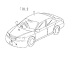
- FIG. 2 is a schematic perspective view of a vehicle 12 in which the vehicle periphery monitoring device 10 shown in FIG. 1 is incorporated.
- the vehicle periphery monitoring device 10 is equipped with a color camera (hereinafter referred to as a "camera 14") that captures a color image (hereinafter referred to as an "image Im") made up from a plurality of color channels, a vehicle speed sensor 16 for detecting a velocity Vs of the vehicle 12, a yaw rate sensor 18 for detecting a yaw rate Yr of the vehicle 12, a brake sensor 20 for detecting an operating amount Br by which a brake pedal is operated by a driver, an electronic control unit (hereinafter referred to as an "ECU 22") that controls the vehicle periphery monitoring device 10, a speaker 24 for issuing an alarm or the like by voice, and a display unit 26 that displays a captured image that is output from the camera 14.
- a color camera hereinafter referred to as a "camera 14”
- image Im a color image
- image Im a color image
- vehicle speed sensor 16 for detecting a velocity Vs of the vehicle 12
- the camera 14 is a camera using light having wavelengths primarily in the visible range, and functions as an image capturing means (image capturing unit) for capturing an image of the periphery of the vehicle 12.
- the camera 14 has characteristics such that, the greater the amount of light reflected from the surface of a subject is, the higher the level of an output signal from the camera becomes, thereby resulting in an increase in brightness, e.g., RGB values, of the image.
- the camera 14 is fixedly disposed (mounted) in a substantially central region of a front bumper of the vehicle 12.
- the image capturing means for capturing an image around the periphery of the vehicle 12 is not limited to the above structure (a so-called monocular camera), but may be a multiocular camera (stereo camera). Further, instead of a color camera, the image capturing means may be a monochromatic camera or an infrared camera, or one or both of such cameras may be used in combination with a color camera. Moreover, if the image capturing means is a monocular camera, then the monocular camera may be combined with a range finding means (radar apparatus).
- radar apparatus range finding means
- the speaker 24 produces a warning sound or the like on the basis of a command from the ECU 22.
- the speaker 24 is mounted on a non-illustrated dashboard of the vehicle 12.
- a speech output function which belongs to another apparatus (e.g., an audio system or a navigation system), may be used as the speaker 24.
- the display unit 26 (see FIGS. 1 and 2 ) is a head-up display (HUD), which is positioned such that a display screen thereof is displayed on the front windshield of the vehicle 12, at a position where the display screen does not obstruct the forward vision of the driver.
- the display unit 26 is not limited to a HUD, but may be a display unit for displaying a map, etc., of a navigation system incorporated in the vehicle 12, or a display unit (multi-information display unit: MID) disposed in a meter unit for displaying mileage information, etc.
- MID multi-information display unit
- the ECU 22 basically includes an input/output unit 28, a processor 30, a display controller 32, and a memory 34.
- Signals from the camera 14, the vehicle speed sensor 16, the yaw rate sensor 18, and the brake sensor 20 are input to the ECU 22 through the input/output unit 28. Further, signals from the ECU 22 are output through the input/output unit 28 to the speaker 24 and the display unit 26.
- the input/output unit 28 includes a non-illustrated A/D conversion circuit for converting input analog signals into digital signals.
- the processor 30 performs processing sequences on the signals from the camera 14, the vehicle speed sensor 16, the yaw rate sensor 18, and the brake sensor 20, and on the basis of results of the processing operations, generates signals that are supplied to the speaker 24 and the display unit 26.
- the processor 30 functions as an identification target area determiner 40 (identification target area determining means), an object identifier 42 (object identifying means), and an object detector 44.
- the various functions of the components of the processor 30 are realized by reading and executing programs stored in the memory 34.
- the programs may be supplied from an external source via a non-illustrated wireless communications unit (mobile phone, smartphone, or the like).
- the display controller 32 is a control circuit for energizing and controlling the display unit 26. By supplying a display control signal to the display unit 26 through the input/output unit 28, the display controller 32 energizes the display unit 26. Accordingly, the display unit 26 is capable of displaying various types of images (the captured image Im, marks, etc.).
- the memory 34 is composed of a random access memory (RAM) for storing captured image signals that have been converted into digital signals, temporary data used in various processing operations, etc., and a read only memory (ROM) for storing executable programs, tables and maps, etc.
- RAM random access memory
- ROM read only memory
- the vehicle periphery monitoring device 10 is basically configured as described above. An outline of operations of the vehicle periphery monitoring device 10 will be described below.
- the ECU 22 converts an analog video signal output from the camera 14 into a digital signal, and temporarily stores the digital signal in the memory 34, at prescribed frame clock interval or period (e.g., at thirty frames per second).
- the ECU 22 then performs various processing operations on the captured image Im (i.e., an image in front of the vehicle 12) which is read from the memory 34.
- the ECU 22 controls each of the output units of the vehicle periphery monitoring device 10 in order to call the attention of the driver. For example, the ECU 22 controls the speaker 24 to output a warning sound, e.g., a succession of blips, and highlights the monitoring object in the captured image Im, which is displayed visually on the display unit 26.
- a warning sound e.g., a succession of blips
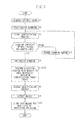
- step S1 for each frame, the ECU 22 acquires a captured image Im of an area that lies within a given angle of view in front of the vehicle 12, which is represented by an output signal from the camera 14.
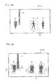
- the captured image Im represents an image area 60 having a horizontally elongate rectangular shape made up of horizontal rows of 1200 pixels and vertical columns of 600 pixels, for example.
- an image region of a postal submission box hereinafter referred to simply as a "post box 62"
- an image region of a utility pole hereinafter referred to simply as a "utility pole 64”
- an image region of a road surface hereinafter referred to simply as a “road surface 65”
- an image region of a first pedestrian hereinafter referred to simply as a “first pedestrian 66”
- an image region of a second pedestrian hereinafter referred to simply as a "second pedestrian 68").
- step S2 the processor 30 initiates a raster scanning process on the captured image Im.
- the raster scanning process refers to a process for sequentially identifying whether or not objects exist in the captured image Im, while a scanning region 70 in the captured image Im is moved along a prescribed scanning direction.
- the scanning region 70 corresponds to a region of interest for identifying whether or not an object including the first pedestrian 66 exists, as well as for identifying the type of object.
- the identification target area determiner 40 sequentially determines the position and scale (size) of the currently specified scanning region 70.
- a rectangular scanning region 70 (the area framed by the dashed line) is set to include substantially the entirety of the first pedestrian 66.
- the position of the scanning region 70 can be specified by a position (hereinafter referred to as a "contact position 72") corresponding to a point of contact between an actual road surface and the first pedestrian.
- step S3 the object identifier 42 (first identifying unit 50) identifies whether at least one type of object exists within the determined scanning region 70 or not.
- first identification process implies an identification process for which an amount of computation needed by the process to identify an object is relatively small, and will hereinafter be described in detail.
- an area candidate extraction unit 46 extracts the scanning region 70 as an area candidate 74 (refer to FIG. 4B ).
- step S4 the identification target area determiner 40 assesses whether or not the scanning process has been completed entirely within the designated area. If the identification target area determiner 40 assesses that the scanning process has not been completed (step S4: NO), then control proceeds to the next step (step S5).
- the designated area which is the object that is scanned, may be the entire image area 60 or a portion of the area.
- the identification target area determiner 40 changes the position or scale of the scanning region 70. More specifically, the identification target area determiner 40 moves the current scanning region 70 to a position where scanning has not yet been performed, and more specifically, moves the current scanning region by a predetermined amount (e.g., by one pixel) in a predetermined scanning direction (e.g., a rightward direction).
- a predetermined amount e.g., by one pixel
- a predetermined scanning direction e.g., a rightward direction
- step S6 the processor 30 terminates the raster scanning process on the captured image Im.
- an area candidate group 75 is an aggregate of area candidates 74 including at least a portion of the post box 62.
- an area candidate group 76 is an aggregate of area candidates 74 including at least a portion of the utility pole 64.
- an area candidate group 77 is an aggregate of area candidates 74 including at least a portion of the first pedestrian 66.
- an area candidate group 78 is an aggregate of area candidates 74 including at least a portion of the second pedestrian 68.
- examples of types of objects that can be identified may include various animals (specifically, mammals such as deer, horses, sheep, dogs, cats, etc., birds, etc.) and artificial structures (specifically, vehicles, markings, utility poles, guardrails, walls, etc.).
- the object identifier 42 serves to detect a living body (a human body or an animal). In this case, by way of the first identification process, the first pedestrian 66 and the second pedestrian 68 are properly identified, whereas the post box 62 and the utility pole 64, which are artificial structures, are mistakenly identified.
- the object identifier 42 may capture the form of an object by performing the simple first identification process, there is a tendency for it not to be possible to accurately detect the position of the object. More specifically, even for the same object, cases may occur in which plural area candidates 74 that differ slightly in position or the like are extracted. In greater detail, as shown in FIG. 4B , in the vicinity of one post box 62, plural area candidates 74, which differ in position or scale, are extracted, and the area candidate group 75 is formed thereby.
- an area classifier 48 performs a clustering process with respect to each of the area candidates 74 that were extracted in step S3, thereby determining at least one of identification target areas 95 to 98 (see FIG. 6A ).
- the clustering process is defined by a process in which data sets are classified and divided into subsets (clusters), and is broadly divided into a hierarchical technique by which classification of data is done hierarchically, and a non-hierarchical technique in which the classification is done according to a particular evaluation function.
- the area classifier 48 performs the clustering process in terms of the position and/or scale of the plural area candidates 74.
- the amount of computation increases substantially in proportion to the square of the number of data, and therefore, as the total number of area candidates 74 increases, significantly more computing time is required for this process.
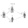
- the identification target area determiner 40 (area classifier 48) divides the image area 60 into a plurality of sub-areas 80, and the clustering process in relation to position is performed with respect to each of representative positions of the area candidates 74 that are calculated in the respective sub-areas 80.
- the image area 60 is divided into a grid pattern, thereby defining a plurality of respective sub-areas 80.
- the rectangular image area 60 is divided into a two-dimensional pattern made up of five rows and ten columns of equal blocks.
- candidate positions 82 which specify the respective positions of the plural area candidates 74, are plotted on the image area 60.
- the candidate positions 82 which are indicated by circles, correspond to the respective contact positions 72 of the area candidates 74, for example.
- a representative position is determined for each of the previously divided sub-areas 80. For example, in the case that three candidate positions 82 exist within one of the sub-areas 80, a statistical value (average value) therefor is calculated, and the statistical value is stored as the representative position in the one sub-area 80 together with the number of (three) candidate positions 82. In addition, using a mean shift method, a maximum of fifty representative positions in the sub-areas 80 are classified in at least one group. When this calculation is made, evaluation values are weighted, respectively, corresponding to the number of candidate positions 82, i.e., depending on the numbers that are indicated in the rectangular cells of FIG. 5B . By this feature, the data amount (total number of different positions) used for the clustering process can be reduced, so that the computation process can be realized at a faster speed.
- candidate position groups 85, 86, 87, 88 are extracted, respectively, corresponding to the four area candidate groups 75 to 78 (see FIG. 4B ).
- reference positions 90, 91, 92, 93 are determined, respectively, corresponding to the candidate position groups 85 to 88.
- the identification target area determiner 40 determines four identification target areas 95, 96, 97, 98 specified from the reference positions 90 to 93.
- a clustering process in relation to scale may also be applied independently or in addition thereto.
- the space coordinate system to which the clustering process is applied may be a three-dimensional space (real space) or a two-dimensional space (e.g., the captured image surface).
- step S8 the object identifier 42 (second identifying unit 52) identifies whether or not at least one type of object exists within the identification target areas 95 to 98 that were determined in step S7.
- the term "second identification process” as used herein implies an identification process for which an amount of computation needed by the process to identify an object is relatively large. Below, differences between the first and second identification processes will be explained.
- the first identification process is a simple process having a relatively short computing time, which enables the form of objects to be detected.
- the second identification process is a detailed process having a relatively long computing time, which enables the form and position of objects to be detected.
- the amount of computation is relatively large (the computing time is relatively long) due to factors such as, for example, [1] the target area on which computation is effected is large, [2] the image resolution is high, [3] the calculation method for the image feature quantities is complex, [4] there are many types of image feature quantities, [5] identification of the types of objects is further performed, [6] the method encompasses the entire content of the first recognition process, or [7] the amount of memory used is large, etc.
- the first identifying unit 50 (or the second identifying unit 52), for example, is an identifying device, which is generated using a machine learning process, with an image feature quantity in the scanning region 70 (or the identification target areas 95 to 98) being input thereto, and information as to whether or not an object exists being output therefrom.
- the machine learning process may be based on any of various algorithms, including a supervised learning algorithm, an unsupervised learning algorithm, and a reinforcement learning process. Examples of learning architecture may include a boosting process including AdaBoost, a support vector machine (SVM), a neural network, and an expectation maximization (EM) algorithm.
- AdaBoost AdaBoost
- SVM support vector machine
- EM expectation maximization
- the object identifier 42 (second identifying unit 52) excludes the post box 62 and the utility pole 64, which are artificial structures, and identifies each of the first pedestrian 66 and the second pedestrian 68.
- the object identifier 42 may perform the second identification process with respect to the identification target areas 95 to 98 that have been suitably classified, so that, compared to the case of regarding all of the area candidates 74 (see FIG. 4B ) as targets to be processed, the amount of computation can be significantly reduced.
- the object detector 44 detects objects that exist within the captured image Im, and in particular, detects the first pedestrian 66 and the second pedestrian 68 that were identified in step S8.
- the object detector 44 may use an identification result in a single frame, or may take into account identification results in a plurality of frames, so that a motion vector of one object can be calculated.
- step S10 the ECU 22 stores in the memory 34 data that are needed for the next cycle of processing operations.
- the data may include attributes of the objects (the first pedestrian 66 and the second pedestrian 68 in FIG. 4A ) that were obtained in step S9, the positions of the identification target areas 97, 98, or the like.
- the vehicle periphery monitoring device 10 is capable of monitoring objects that exist in front of the vehicle 12 at prescribed time intervals.
- the object identifier 42 includes the first identifying unit 50 for which the computation amount thereof required by the identification process for identifying objects is relatively small, and the second identifying unit 52 for which the computation amount thereof is relatively large.
- the identification target area determiner 40 determines at least one of the identification target areas 95 to 98 to be subjected to the identification process by the second identifying unit 52, by performing the clustering process in relation to position and/or scale, with respect to plural area candidates 74 extracted by the first identifying unit 50 as areas in which objects exist.
- the identification process can be executed by the second identifying unit 52 for which the computation amount thereof is relatively large, whereby an improvement in accuracy and a reduction in the amount of computation in relation to the object identification process can both be achieved.
- an area candidate group 78 is extracted in which scales of multiple levels are mixed.
- an identification target area 99 is set having a scale of an intermediate value within the aforementioned multiple levels (see FIG. 7B ).
- the area classifier 48 may classify the plural area candidates 74 into two or more groups depending on scale, and then perform the clustering process on each of such groups. In this manner, the second identification process is executed with respect to the identification target areas 105, etc. (see FIG. 9 ), that have been suitably classified by scale, whereby error factors due to variations in scale can be reduced, and identification accuracy can be further enhanced.
- FIG. 8 is a flowchart used for describing a clustering process according to the first improvement.
- step S71 the area classifier 48 performs a clustering process (hereinafter referred to as a first clustering process) in relation at least to position, thereby classifying each of the area candidates 74 into at least one position group.
- a clustering process hereinafter referred to as a first clustering process
- step S72 based on the classification result of step S71, the area classifier 48 initiates a secondary clustering process. Below, the secondary clustering process will be explained.
- the area classifier 48 selects one position group that has not yet been selected, i.e., one area candidate group 78 (step S73), and thereafter carries out a scale division of each of the area candidates 74 that belong to the position group (step S74).
- the area classifier 48 classifies plots of multidimensional coordinates, which are defined by a scale on the horizontal axis and coordinates (positions) on the vertical axis, into two or more levels depending on scale. As a result, the respective area candidates 74 are classified into, for example, three groups 101, 102, and 103.
- step S75 the area classifier 48 executes the clustering process in relation to position and/or scale for each of the groups that were classified in step S73.
- the clustering process can be executed in the same manner as in step S7, and thus explanations thereof are omitted.
- step S76 NO
- steps S73 through S75 are repeated sequentially.
- step S76: YES the secondary clustering process is brought to an end.
- the area classifier 48 determines the identification target areas 105, 106, 107 respectively for the groups 101 to 103 that were classified by the clustering process.
- the area classifier 48 is capable of determining, respectively, an identification target area 105 of a small scale, an identification target area 106 of an intermediate scale, and an identification target area 107 of a large scale.
- the identification target area determiner 40 after having classified the plural area candidates 74 into at least one position group by performing the previous stage clustering process in relation to at least position, classifies the area candidates 74 belonging to the at least one position group into two or more groups depending on scale, and then determines the identification target areas 105 to 107 for the respective area candidates.
- the area classifier 48 classifies the plural area candidates 74 into two or more groups depending on scale.
- the plural area candidates 74 are classified into an area candidate group 110, which is an aggregate of the area candidates 74 having a scale that is greater than a predetermined threshold value, and an area candidate group 111, which is an aggregate of the area candidates 74 having a scale that is equal to or less than the predetermined threshold value.
- the area classifier 48 determines identification target areas 112, 113 by performing the clustering process on each of the groups. More specifically, with respect to the same second pedestrian 68, the area classifier 48 is capable of determining, respectively, an identification target area 112 of a small scale, and an identification target area 113 of a large scale.
- the clustering process may be performed only on the number of classified groups, whereby identification accuracy can be enhanced together with realizing a reduction in the amount of computation.
- the aforementioned image processing sequence is carried out on the captured image Im, which is produced by the monocular camera (camera 14).
- the same advantages as those described above can be obtained by performing the image processing sequence on a captured image that is produced by a multiocular camera (stereo camera).
Landscapes
- Engineering & Computer Science (AREA)
- Multimedia (AREA)
- Physics & Mathematics (AREA)
- General Physics & Mathematics (AREA)
- Theoretical Computer Science (AREA)
- Human Computer Interaction (AREA)
- Signal Processing (AREA)
- Mechanical Engineering (AREA)
- Image Analysis (AREA)
- Traffic Control Systems (AREA)
- Closed-Circuit Television Systems (AREA)
Applications Claiming Priority (2)
| Application Number | Priority Date | Filing Date | Title |
|---|---|---|---|
| JP2012280938 | 2012-12-25 | ||
| PCT/JP2013/073830 WO2014103433A1 (ja) | 2012-12-25 | 2013-09-04 | 車両周辺監視装置 |
Publications (3)
| Publication Number | Publication Date |
|---|---|
| EP2940656A1 true EP2940656A1 (de) | 2015-11-04 |
| EP2940656A4 EP2940656A4 (de) | 2016-10-12 |
| EP2940656B1 EP2940656B1 (de) | 2024-01-31 |
Family
ID=51020537
Family Applications (1)
| Application Number | Title | Priority Date | Filing Date |
|---|---|---|---|
| EP13867122.7A Active EP2940656B1 (de) | 2012-12-25 | 2013-09-04 | Fahrzeugumfeldüberwachungsvorrichtung |
Country Status (6)
| Country | Link |
|---|---|
| US (1) | US9776564B2 (de) |
| EP (1) | EP2940656B1 (de) |
| JP (1) | JP5922257B2 (de) |
| CN (1) | CN104885122B (de) |
| CA (1) | CA2896291A1 (de) |
| WO (1) | WO2014103433A1 (de) |
Cited By (1)
| Publication number | Priority date | Publication date | Assignee | Title |
|---|---|---|---|---|
| EP3249629A3 (de) * | 2016-05-27 | 2018-03-21 | Kabushiki Kaisha Toshiba | Informationsverarbeitungsvorrichtung, informationsverarbeitungsverfahren und fahrzeug |
Families Citing this family (14)
| Publication number | Priority date | Publication date | Assignee | Title |
|---|---|---|---|---|
| KR101543105B1 (ko) * | 2013-12-09 | 2015-08-07 | 현대자동차주식회사 | 보행자 인식 장치 및 그의 처리 방법과 이를 지원하는 차량 |
| JP6474396B2 (ja) * | 2014-06-03 | 2019-02-27 | 住友重機械工業株式会社 | 人検知システム及びショベル |
| DE102016205339A1 (de) * | 2016-03-31 | 2017-10-05 | Siemens Aktiengesellschaft | Verfahren und System zum Erkennen von Hindernissen in einem Gefahrraum vor einem Schienenfahrzeug |
| TWI592883B (zh) | 2016-04-22 | 2017-07-21 | 財團法人車輛研究測試中心 | Image recognition system and its adaptive learning method |
| JP2018036937A (ja) * | 2016-09-01 | 2018-03-08 | 住友電気工業株式会社 | 画像処理装置、画像処理システム、画像処理プログラムおよびラベル |
| WO2018173846A1 (ja) | 2017-03-22 | 2018-09-27 | 日本電気株式会社 | 物体検出装置、物体検出方法および物体検出プログラム |
| US10108867B1 (en) * | 2017-04-25 | 2018-10-23 | Uber Technologies, Inc. | Image-based pedestrian detection |
| DE102017208718A1 (de) * | 2017-05-23 | 2018-11-29 | Conti Temic Microelectronic Gmbh | Verfahren zur Erkennung von Objekten in einem Bild einer Kamera |
| DE102018209388A1 (de) * | 2018-06-13 | 2019-12-19 | Robert Bosch Gmbh | Erkennung fahrtrelevanter Situationen auf größere Entfernung |
| WO2020054260A1 (ja) * | 2018-09-12 | 2020-03-19 | 日立オートモティブシステムズ株式会社 | 画像認識装置 |
| CN111242117A (zh) * | 2018-11-28 | 2020-06-05 | 佳能株式会社 | 检测装置和方法及图像处理装置和系统 |
| CN113075648B (zh) * | 2021-03-19 | 2024-05-17 | 中国舰船研究设计中心 | 一种无人集群目标定位信息的聚类与滤波方法 |
| JP7633508B2 (ja) * | 2021-03-31 | 2025-02-20 | シンフォニアテクノロジー株式会社 | 作業機械周辺検出対象物位置検出システム、作業機械周辺検出対象物位置検出プログラム |
| CN113240670B (zh) * | 2021-06-16 | 2024-08-13 | 亿嘉和科技股份有限公司 | 带电作业场景下针对待作业物体的图像分割方法 |
Family Cites Families (17)
| Publication number | Priority date | Publication date | Assignee | Title |
|---|---|---|---|---|
| US7783403B2 (en) * | 1994-05-23 | 2010-08-24 | Automotive Technologies International, Inc. | System and method for preventing vehicular accidents |
| US9052386B2 (en) * | 2002-02-06 | 2015-06-09 | Nice Systems, Ltd | Method and apparatus for video frame sequence-based object tracking |
| AU2003225228A1 (en) * | 2002-05-03 | 2003-11-17 | Donnelly Corporation | Object detection system for vehicle |
| JP3868915B2 (ja) * | 2003-03-12 | 2007-01-17 | 株式会社東芝 | 前方監視装置及びその方法 |
| JP4652698B2 (ja) * | 2004-02-23 | 2011-03-16 | 独立行政法人科学技術振興機構 | 画像認識装置、画像認識方法及びプログラム |
| US8184159B2 (en) * | 2007-03-26 | 2012-05-22 | Trw Automotive U.S. Llc | Forward looking sensor system |
| JP4359710B2 (ja) * | 2008-02-04 | 2009-11-04 | 本田技研工業株式会社 | 車両周辺監視装置、車両、車両周辺監視用プログラム、車両周辺監視方法 |
| JP4521642B2 (ja) * | 2008-02-13 | 2010-08-11 | 本田技研工業株式会社 | 車両周辺監視装置、車両、車両周辺監視プログラム |
| JP5083658B2 (ja) * | 2008-03-26 | 2012-11-28 | 本田技研工業株式会社 | 車両用車線認識装置、車両、及び車両用車線認識プログラム |
| JP2010039968A (ja) * | 2008-08-08 | 2010-02-18 | Hitachi Ltd | オブジェクト検出装置及び検出方法 |
| US8260539B2 (en) * | 2010-05-12 | 2012-09-04 | GM Global Technology Operations LLC | Object and vehicle detection and tracking using 3-D laser rangefinder |
| US8548256B2 (en) * | 2010-07-01 | 2013-10-01 | Intellectual Ventures Fund 83 Llc | Method for fast scene matching |
| US8724910B1 (en) * | 2010-08-31 | 2014-05-13 | Google Inc. | Selection of representative images |
| JP5580233B2 (ja) * | 2011-03-22 | 2014-08-27 | 富士重工業株式会社 | 車外監視装置および車外監視方法 |
| EP2717219B1 (de) * | 2011-06-02 | 2018-05-30 | Panasonic Intellectual Property Management Co., Ltd. | Objekterkennungsvorrichtung, objekterkennungsverfahren und objekterkennungsprogramm |
| EP2696326A4 (de) | 2011-06-10 | 2015-12-02 | Panasonic Corp | Anzeigevorrichtung für objekterkennungsrahmen und anzeigeverfahren für objekterkennungsrahmen |
| JP5612621B2 (ja) * | 2012-02-28 | 2014-10-22 | 富士重工業株式会社 | 車外環境認識装置 |
-
2013
- 2013-09-04 CN CN201380067434.7A patent/CN104885122B/zh active Active
- 2013-09-04 US US14/654,591 patent/US9776564B2/en active Active
- 2013-09-04 CA CA2896291A patent/CA2896291A1/en not_active Abandoned
- 2013-09-04 EP EP13867122.7A patent/EP2940656B1/de active Active
- 2013-09-04 WO PCT/JP2013/073830 patent/WO2014103433A1/ja not_active Ceased
- 2013-09-04 JP JP2014554183A patent/JP5922257B2/ja not_active Expired - Fee Related
Cited By (3)
| Publication number | Priority date | Publication date | Assignee | Title |
|---|---|---|---|---|
| EP3249629A3 (de) * | 2016-05-27 | 2018-03-21 | Kabushiki Kaisha Toshiba | Informationsverarbeitungsvorrichtung, informationsverarbeitungsverfahren und fahrzeug |
| US10451735B2 (en) | 2016-05-27 | 2019-10-22 | Kabushiki Kaisha Toshiba | Information processing device, information processing method, and vehicle |
| US11536833B2 (en) | 2016-05-27 | 2022-12-27 | Kabushiki Kaisha Toshiba | Information processing device, information processing method, and vehicle |
Also Published As
| Publication number | Publication date |
|---|---|
| US9776564B2 (en) | 2017-10-03 |
| CN104885122A (zh) | 2015-09-02 |
| CA2896291A1 (en) | 2014-07-03 |
| EP2940656A4 (de) | 2016-10-12 |
| JP5922257B2 (ja) | 2016-05-24 |
| WO2014103433A1 (ja) | 2014-07-03 |
| EP2940656B1 (de) | 2024-01-31 |
| US20150343948A1 (en) | 2015-12-03 |
| CN104885122B (zh) | 2017-06-23 |
| JPWO2014103433A1 (ja) | 2017-01-12 |
Similar Documents
| Publication | Publication Date | Title |
|---|---|---|
| US9776564B2 (en) | Vehicle periphery monitoring device | |
| CN110163904B (zh) | 对象标注方法、移动控制方法、装置、设备及存储介质 | |
| KR102109941B1 (ko) | 라이다 센서 및 카메라를 이용한 객체 검출 방법 및 그를 위한 장치 | |
| WO2019223582A1 (en) | Target detection method and system | |
| US9292751B2 (en) | Object identifier | |
| US20210311169A1 (en) | Radar data processing device, object determination device, radar data processing method, and object determination method | |
| CN113408324A (zh) | 目标检测方法、装置及系统、高级驾驶辅助系统 | |
| US7974445B2 (en) | Vehicle periphery monitoring device, vehicle, and vehicle periphery monitoring program | |
| JP2014106685A (ja) | 車両周辺監視装置 | |
| US20230245323A1 (en) | Object tracking device, object tracking method, and storage medium | |
| CN109238281B (zh) | 基于图像螺旋线的视觉导航及避障方法 | |
| CN114898319A (zh) | 基于多传感器决策级信息融合的车型识别方法及系统 | |
| CN107292214A (zh) | 车道偏离检测方法、装置及车辆 | |
| CN113449629B (zh) | 基于行车视频的车道线虚实识别装置、方法、设备及介质 | |
| CN118097933B (zh) | 双光谱雷视一体机交通事件监测方法、系统、设备及介质 | |
| CN119863768A (zh) | 多任务模型的训练方法、图像处理方法、装置及设备 | |
| CN114677658B (zh) | 十亿像素动态大场景图像采集和多目标检测方法及装置 | |
| Mori et al. | Classification of pole-like objects using point clouds and images captured by mobile mapping systems | |
| CN117789193A (zh) | 基于二次增强的多模态数据融合3d目标检测方法 | |
| CN111332305A (zh) | 一种主动预警型交通道路感知辅助驾驶预警系统 | |
| KR20240160136A (ko) | 비전 기반 감지 시스템 | |
| US20210097340A1 (en) | Teaching Data Creation Device and Image Classification Device | |
| FI131627B1 (en) | Controlling a mobile robot based on computerized models | |
| CN116994223B (zh) | 目标检测方法及模型、预警方法、车载设备及存储介质 | |
| CN115131594B (zh) | 一种基于集成学习的毫米波雷达数据点分类方法及装置 |
Legal Events
| Date | Code | Title | Description |
|---|---|---|---|
| PUAI | Public reference made under article 153(3) epc to a published international application that has entered the european phase |
Free format text: ORIGINAL CODE: 0009012 |
|
| 17P | Request for examination filed |
Effective date: 20150623 |
|
| AK | Designated contracting states |
Kind code of ref document: A1 Designated state(s): AL AT BE BG CH CY CZ DE DK EE ES FI FR GB GR HR HU IE IS IT LI LT LU LV MC MK MT NL NO PL PT RO RS SE SI SK SM TR |
|
| AX | Request for extension of the european patent |
Extension state: BA ME |
|
| DAX | Request for extension of the european patent (deleted) | ||
| A4 | Supplementary search report drawn up and despatched |
Effective date: 20160908 |
|
| RIC1 | Information provided on ipc code assigned before grant |
Ipc: B60Q 9/00 20060101ALI20160902BHEP Ipc: G08G 1/16 20060101AFI20160902BHEP Ipc: G06K 9/00 20060101ALI20160902BHEP |
|
| STAA | Information on the status of an ep patent application or granted ep patent |
Free format text: STATUS: EXAMINATION IS IN PROGRESS |
|
| 17Q | First examination report despatched |
Effective date: 20190103 |
|
| REG | Reference to a national code |
Ref legal event code: R079 Free format text: PREVIOUS MAIN CLASS: G06T0007000000 Ipc: G08G0001160000 Ref country code: DE Ref legal event code: R079 Ref document number: 602013085252 Country of ref document: DE Free format text: PREVIOUS MAIN CLASS: G06T0007000000 Ipc: G08G0001160000 |
|
| GRAP | Despatch of communication of intention to grant a patent |
Free format text: ORIGINAL CODE: EPIDOSNIGR1 |
|
| STAA | Information on the status of an ep patent application or granted ep patent |
Free format text: STATUS: GRANT OF PATENT IS INTENDED |
|
| RIC1 | Information provided on ipc code assigned before grant |
Ipc: B60Q 9/00 20060101ALI20230713BHEP Ipc: G06V 40/10 20220101ALI20230713BHEP Ipc: G06V 20/58 20220101ALI20230713BHEP Ipc: G08G 1/16 20060101AFI20230713BHEP |
|
| GRAJ | Information related to disapproval of communication of intention to grant by the applicant or resumption of examination proceedings by the epo deleted |
Free format text: ORIGINAL CODE: EPIDOSDIGR1 |
|
| STAA | Information on the status of an ep patent application or granted ep patent |
Free format text: STATUS: EXAMINATION IS IN PROGRESS |
|
| INTG | Intention to grant announced |
Effective date: 20230731 |
|
| GRAP | Despatch of communication of intention to grant a patent |
Free format text: ORIGINAL CODE: EPIDOSNIGR1 |
|
| STAA | Information on the status of an ep patent application or granted ep patent |
Free format text: STATUS: GRANT OF PATENT IS INTENDED |
|
| INTC | Intention to grant announced (deleted) | ||
| INTG | Intention to grant announced |
Effective date: 20230912 |
|
| GRAS | Grant fee paid |
Free format text: ORIGINAL CODE: EPIDOSNIGR3 |
|
| GRAA | (expected) grant |
Free format text: ORIGINAL CODE: 0009210 |
|
| STAA | Information on the status of an ep patent application or granted ep patent |
Free format text: STATUS: THE PATENT HAS BEEN GRANTED |
|
| AK | Designated contracting states |
Kind code of ref document: B1 Designated state(s): AL AT BE BG CH CY CZ DE DK EE ES FI FR GB GR HR HU IE IS IT LI LT LU LV MC MK MT NL NO PL PT RO RS SE SI SK SM TR |
|
| REG | Reference to a national code |
Ref country code: GB Ref legal event code: FG4D Ref country code: CH Ref legal event code: EP |
|
| REG | Reference to a national code |
Ref country code: DE Ref legal event code: R096 Ref document number: 602013085252 Country of ref document: DE |
|
| REG | Reference to a national code |
Ref country code: IE Ref legal event code: FG4D |
|
| REG | Reference to a national code |
Ref country code: LT Ref legal event code: MG9D |
|
| REG | Reference to a national code |
Ref country code: NL Ref legal event code: MP Effective date: 20240131 |
|
| PG25 | Lapsed in a contracting state [announced via postgrant information from national office to epo] |
Ref country code: IS Free format text: LAPSE BECAUSE OF FAILURE TO SUBMIT A TRANSLATION OF THE DESCRIPTION OR TO PAY THE FEE WITHIN THE PRESCRIBED TIME-LIMIT Effective date: 20240531 |
|
| PG25 | Lapsed in a contracting state [announced via postgrant information from national office to epo] |
Ref country code: LT Free format text: LAPSE BECAUSE OF FAILURE TO SUBMIT A TRANSLATION OF THE DESCRIPTION OR TO PAY THE FEE WITHIN THE PRESCRIBED TIME-LIMIT Effective date: 20240131 |
|
| PG25 | Lapsed in a contracting state [announced via postgrant information from national office to epo] |
Ref country code: GR Free format text: LAPSE BECAUSE OF FAILURE TO SUBMIT A TRANSLATION OF THE DESCRIPTION OR TO PAY THE FEE WITHIN THE PRESCRIBED TIME-LIMIT Effective date: 20240501 |
|
| REG | Reference to a national code |
Ref country code: AT Ref legal event code: MK05 Ref document number: 1654402 Country of ref document: AT Kind code of ref document: T Effective date: 20240131 |
|
| PG25 | Lapsed in a contracting state [announced via postgrant information from national office to epo] |
Ref country code: RS Free format text: LAPSE BECAUSE OF FAILURE TO SUBMIT A TRANSLATION OF THE DESCRIPTION OR TO PAY THE FEE WITHIN THE PRESCRIBED TIME-LIMIT Effective date: 20240430 Ref country code: HR Free format text: LAPSE BECAUSE OF FAILURE TO SUBMIT A TRANSLATION OF THE DESCRIPTION OR TO PAY THE FEE WITHIN THE PRESCRIBED TIME-LIMIT Effective date: 20240131 Ref country code: NL Free format text: LAPSE BECAUSE OF FAILURE TO SUBMIT A TRANSLATION OF THE DESCRIPTION OR TO PAY THE FEE WITHIN THE PRESCRIBED TIME-LIMIT Effective date: 20240131 |
|
| PG25 | Lapsed in a contracting state [announced via postgrant information from national office to epo] |
Ref country code: ES Free format text: LAPSE BECAUSE OF FAILURE TO SUBMIT A TRANSLATION OF THE DESCRIPTION OR TO PAY THE FEE WITHIN THE PRESCRIBED TIME-LIMIT Effective date: 20240131 |
|
| PG25 | Lapsed in a contracting state [announced via postgrant information from national office to epo] |
Ref country code: AT Free format text: LAPSE BECAUSE OF FAILURE TO SUBMIT A TRANSLATION OF THE DESCRIPTION OR TO PAY THE FEE WITHIN THE PRESCRIBED TIME-LIMIT Effective date: 20240131 |
|
| PG25 | Lapsed in a contracting state [announced via postgrant information from national office to epo] |
Ref country code: RS Free format text: LAPSE BECAUSE OF FAILURE TO SUBMIT A TRANSLATION OF THE DESCRIPTION OR TO PAY THE FEE WITHIN THE PRESCRIBED TIME-LIMIT Effective date: 20240430 Ref country code: NO Free format text: LAPSE BECAUSE OF FAILURE TO SUBMIT A TRANSLATION OF THE DESCRIPTION OR TO PAY THE FEE WITHIN THE PRESCRIBED TIME-LIMIT Effective date: 20240430 Ref country code: NL Free format text: LAPSE BECAUSE OF FAILURE TO SUBMIT A TRANSLATION OF THE DESCRIPTION OR TO PAY THE FEE WITHIN THE PRESCRIBED TIME-LIMIT Effective date: 20240131 Ref country code: LT Free format text: LAPSE BECAUSE OF FAILURE TO SUBMIT A TRANSLATION OF THE DESCRIPTION OR TO PAY THE FEE WITHIN THE PRESCRIBED TIME-LIMIT Effective date: 20240131 Ref country code: IS Free format text: LAPSE BECAUSE OF FAILURE TO SUBMIT A TRANSLATION OF THE DESCRIPTION OR TO PAY THE FEE WITHIN THE PRESCRIBED TIME-LIMIT Effective date: 20240531 Ref country code: HR Free format text: LAPSE BECAUSE OF FAILURE TO SUBMIT A TRANSLATION OF THE DESCRIPTION OR TO PAY THE FEE WITHIN THE PRESCRIBED TIME-LIMIT Effective date: 20240131 Ref country code: GR Free format text: LAPSE BECAUSE OF FAILURE TO SUBMIT A TRANSLATION OF THE DESCRIPTION OR TO PAY THE FEE WITHIN THE PRESCRIBED TIME-LIMIT Effective date: 20240501 Ref country code: FI Free format text: LAPSE BECAUSE OF FAILURE TO SUBMIT A TRANSLATION OF THE DESCRIPTION OR TO PAY THE FEE WITHIN THE PRESCRIBED TIME-LIMIT Effective date: 20240131 Ref country code: ES Free format text: LAPSE BECAUSE OF FAILURE TO SUBMIT A TRANSLATION OF THE DESCRIPTION OR TO PAY THE FEE WITHIN THE PRESCRIBED TIME-LIMIT Effective date: 20240131 Ref country code: BG Free format text: LAPSE BECAUSE OF FAILURE TO SUBMIT A TRANSLATION OF THE DESCRIPTION OR TO PAY THE FEE WITHIN THE PRESCRIBED TIME-LIMIT Effective date: 20240131 Ref country code: AT Free format text: LAPSE BECAUSE OF FAILURE TO SUBMIT A TRANSLATION OF THE DESCRIPTION OR TO PAY THE FEE WITHIN THE PRESCRIBED TIME-LIMIT Effective date: 20240131 |
|
| PG25 | Lapsed in a contracting state [announced via postgrant information from national office to epo] |
Ref country code: PT Free format text: LAPSE BECAUSE OF FAILURE TO SUBMIT A TRANSLATION OF THE DESCRIPTION OR TO PAY THE FEE WITHIN THE PRESCRIBED TIME-LIMIT Effective date: 20240531 Ref country code: PL Free format text: LAPSE BECAUSE OF FAILURE TO SUBMIT A TRANSLATION OF THE DESCRIPTION OR TO PAY THE FEE WITHIN THE PRESCRIBED TIME-LIMIT Effective date: 20240131 |
|
| PG25 | Lapsed in a contracting state [announced via postgrant information from national office to epo] |
Ref country code: SE Free format text: LAPSE BECAUSE OF FAILURE TO SUBMIT A TRANSLATION OF THE DESCRIPTION OR TO PAY THE FEE WITHIN THE PRESCRIBED TIME-LIMIT Effective date: 20240131 Ref country code: PT Free format text: LAPSE BECAUSE OF FAILURE TO SUBMIT A TRANSLATION OF THE DESCRIPTION OR TO PAY THE FEE WITHIN THE PRESCRIBED TIME-LIMIT Effective date: 20240531 Ref country code: PL Free format text: LAPSE BECAUSE OF FAILURE TO SUBMIT A TRANSLATION OF THE DESCRIPTION OR TO PAY THE FEE WITHIN THE PRESCRIBED TIME-LIMIT Effective date: 20240131 Ref country code: LV Free format text: LAPSE BECAUSE OF FAILURE TO SUBMIT A TRANSLATION OF THE DESCRIPTION OR TO PAY THE FEE WITHIN THE PRESCRIBED TIME-LIMIT Effective date: 20240131 |
|
| PGFP | Annual fee paid to national office [announced via postgrant information from national office to epo] |
Ref country code: DE Payment date: 20240827 Year of fee payment: 12 |
|
| PG25 | Lapsed in a contracting state [announced via postgrant information from national office to epo] |
Ref country code: DK Free format text: LAPSE BECAUSE OF FAILURE TO SUBMIT A TRANSLATION OF THE DESCRIPTION OR TO PAY THE FEE WITHIN THE PRESCRIBED TIME-LIMIT Effective date: 20240131 |
|
| PG25 | Lapsed in a contracting state [announced via postgrant information from national office to epo] |
Ref country code: SM Free format text: LAPSE BECAUSE OF FAILURE TO SUBMIT A TRANSLATION OF THE DESCRIPTION OR TO PAY THE FEE WITHIN THE PRESCRIBED TIME-LIMIT Effective date: 20240131 |
|
| PG25 | Lapsed in a contracting state [announced via postgrant information from national office to epo] |
Ref country code: EE Free format text: LAPSE BECAUSE OF FAILURE TO SUBMIT A TRANSLATION OF THE DESCRIPTION OR TO PAY THE FEE WITHIN THE PRESCRIBED TIME-LIMIT Effective date: 20240131 Ref country code: CZ Free format text: LAPSE BECAUSE OF FAILURE TO SUBMIT A TRANSLATION OF THE DESCRIPTION OR TO PAY THE FEE WITHIN THE PRESCRIBED TIME-LIMIT Effective date: 20240131 |
|
| PG25 | Lapsed in a contracting state [announced via postgrant information from national office to epo] |
Ref country code: SK Free format text: LAPSE BECAUSE OF FAILURE TO SUBMIT A TRANSLATION OF THE DESCRIPTION OR TO PAY THE FEE WITHIN THE PRESCRIBED TIME-LIMIT Effective date: 20240131 |
|
| PG25 | Lapsed in a contracting state [announced via postgrant information from national office to epo] |
Ref country code: SM Free format text: LAPSE BECAUSE OF FAILURE TO SUBMIT A TRANSLATION OF THE DESCRIPTION OR TO PAY THE FEE WITHIN THE PRESCRIBED TIME-LIMIT Effective date: 20240131 Ref country code: SK Free format text: LAPSE BECAUSE OF FAILURE TO SUBMIT A TRANSLATION OF THE DESCRIPTION OR TO PAY THE FEE WITHIN THE PRESCRIBED TIME-LIMIT Effective date: 20240131 Ref country code: RO Free format text: LAPSE BECAUSE OF FAILURE TO SUBMIT A TRANSLATION OF THE DESCRIPTION OR TO PAY THE FEE WITHIN THE PRESCRIBED TIME-LIMIT Effective date: 20240131 Ref country code: EE Free format text: LAPSE BECAUSE OF FAILURE TO SUBMIT A TRANSLATION OF THE DESCRIPTION OR TO PAY THE FEE WITHIN THE PRESCRIBED TIME-LIMIT Effective date: 20240131 Ref country code: DK Free format text: LAPSE BECAUSE OF FAILURE TO SUBMIT A TRANSLATION OF THE DESCRIPTION OR TO PAY THE FEE WITHIN THE PRESCRIBED TIME-LIMIT Effective date: 20240131 Ref country code: CZ Free format text: LAPSE BECAUSE OF FAILURE TO SUBMIT A TRANSLATION OF THE DESCRIPTION OR TO PAY THE FEE WITHIN THE PRESCRIBED TIME-LIMIT Effective date: 20240131 |
|
| REG | Reference to a national code |
Ref country code: DE Ref legal event code: R097 Ref document number: 602013085252 Country of ref document: DE |
|
| PG25 | Lapsed in a contracting state [announced via postgrant information from national office to epo] |
Ref country code: IT Free format text: LAPSE BECAUSE OF FAILURE TO SUBMIT A TRANSLATION OF THE DESCRIPTION OR TO PAY THE FEE WITHIN THE PRESCRIBED TIME-LIMIT Effective date: 20240131 |
|
| PLBE | No opposition filed within time limit |
Free format text: ORIGINAL CODE: 0009261 |
|
| STAA | Information on the status of an ep patent application or granted ep patent |
Free format text: STATUS: NO OPPOSITION FILED WITHIN TIME LIMIT |
|
| PG25 | Lapsed in a contracting state [announced via postgrant information from national office to epo] |
Ref country code: IT Free format text: LAPSE BECAUSE OF FAILURE TO SUBMIT A TRANSLATION OF THE DESCRIPTION OR TO PAY THE FEE WITHIN THE PRESCRIBED TIME-LIMIT Effective date: 20240131 |
|
| 26N | No opposition filed |
Effective date: 20241101 |
|
| PG25 | Lapsed in a contracting state [announced via postgrant information from national office to epo] |
Ref country code: SI Free format text: LAPSE BECAUSE OF FAILURE TO SUBMIT A TRANSLATION OF THE DESCRIPTION OR TO PAY THE FEE WITHIN THE PRESCRIBED TIME-LIMIT Effective date: 20240131 Ref country code: MC Free format text: LAPSE BECAUSE OF FAILURE TO SUBMIT A TRANSLATION OF THE DESCRIPTION OR TO PAY THE FEE WITHIN THE PRESCRIBED TIME-LIMIT Effective date: 20240131 |
|
| REG | Reference to a national code |
Ref country code: CH Ref legal event code: PL |
|
| PG25 | Lapsed in a contracting state [announced via postgrant information from national office to epo] |
Ref country code: LU Free format text: LAPSE BECAUSE OF NON-PAYMENT OF DUE FEES Effective date: 20240904 |
|
| GBPC | Gb: european patent ceased through non-payment of renewal fee |
Effective date: 20240904 |
|
| PG25 | Lapsed in a contracting state [announced via postgrant information from national office to epo] |
Ref country code: GB Free format text: LAPSE BECAUSE OF NON-PAYMENT OF DUE FEES Effective date: 20240904 |
|
| REG | Reference to a national code |
Ref country code: BE Ref legal event code: MM Effective date: 20240930 |
|
| PG25 | Lapsed in a contracting state [announced via postgrant information from national office to epo] |
Ref country code: BE Free format text: LAPSE BECAUSE OF NON-PAYMENT OF DUE FEES Effective date: 20240930 |
|
| PG25 | Lapsed in a contracting state [announced via postgrant information from national office to epo] |
Ref country code: FR Free format text: LAPSE BECAUSE OF NON-PAYMENT OF DUE FEES Effective date: 20240930 |
|
| PG25 | Lapsed in a contracting state [announced via postgrant information from national office to epo] |
Ref country code: CH Free format text: LAPSE BECAUSE OF NON-PAYMENT OF DUE FEES Effective date: 20240930 |
|
| PG25 | Lapsed in a contracting state [announced via postgrant information from national office to epo] |
Ref country code: IE Free format text: LAPSE BECAUSE OF NON-PAYMENT OF DUE FEES Effective date: 20240904 |
|
| PG25 | Lapsed in a contracting state [announced via postgrant information from national office to epo] |
Ref country code: CY Free format text: LAPSE BECAUSE OF FAILURE TO SUBMIT A TRANSLATION OF THE DESCRIPTION OR TO PAY THE FEE WITHIN THE PRESCRIBED TIME-LIMIT; INVALID AB INITIO Effective date: 20130904 |
|
| PG25 | Lapsed in a contracting state [announced via postgrant information from national office to epo] |
Ref country code: HU Free format text: LAPSE BECAUSE OF FAILURE TO SUBMIT A TRANSLATION OF THE DESCRIPTION OR TO PAY THE FEE WITHIN THE PRESCRIBED TIME-LIMIT; INVALID AB INITIO Effective date: 20130904 |