EP2940675A2 - Système d'estimation de traction de piste et d'établissement de rapports - Google Patents
Système d'estimation de traction de piste et d'établissement de rapports Download PDFInfo
- Publication number
- EP2940675A2 EP2940675A2 EP15165322.7A EP15165322A EP2940675A2 EP 2940675 A2 EP2940675 A2 EP 2940675A2 EP 15165322 A EP15165322 A EP 15165322A EP 2940675 A2 EP2940675 A2 EP 2940675A2
- Authority
- EP
- European Patent Office
- Prior art keywords
- runway
- traction
- estimation
- sensor input
- data
- Prior art date
- Legal status (The legal status is an assumption and is not a legal conclusion. Google has not performed a legal analysis and makes no representation as to the accuracy of the status listed.)
- Granted
Links
Images


Classifications
-
- G—PHYSICS
- G05—CONTROLLING; REGULATING
- G05D—SYSTEMS FOR CONTROLLING OR REGULATING NON-ELECTRIC VARIABLES
- G05D1/00—Control of position, course, altitude or attitude of land, water, air or space vehicles, e.g. using automatic pilots
- G05D1/0083—Control of position, course, altitude or attitude of land, water, air or space vehicles, e.g. using automatic pilots to help an aircraft pilot in the rolling phase
-
- B—PERFORMING OPERATIONS; TRANSPORTING
- B64—AIRCRAFT; AVIATION; COSMONAUTICS
- B64C—AEROPLANES; HELICOPTERS
- B64C25/00—Alighting gear
- B64C25/32—Alighting gear characterised by elements which contact the ground or similar surface
- B64C25/42—Arrangement or adaptation of brakes
- B64C25/426—Braking devices providing an automatic sequence of braking
-
- G—PHYSICS
- G08—SIGNALLING
- G08G—TRAFFIC CONTROL SYSTEMS
- G08G5/00—Traffic control systems for aircraft
- G08G5/20—Arrangements for acquiring, generating, sharing or displaying traffic information
- G08G5/21—Arrangements for acquiring, generating, sharing or displaying traffic information located onboard the aircraft
-
- G—PHYSICS
- G08—SIGNALLING
- G08G—TRAFFIC CONTROL SYSTEMS
- G08G5/00—Traffic control systems for aircraft
- G08G5/50—Navigation or guidance aids
- G08G5/51—Navigation or guidance aids for control when on the ground, e.g. taxiing or rolling
-
- G—PHYSICS
- G08—SIGNALLING
- G08G—TRAFFIC CONTROL SYSTEMS
- G08G5/00—Traffic control systems for aircraft
- G08G5/50—Navigation or guidance aids
- G08G5/54—Navigation or guidance aids for approach or landing
Definitions
- the present disclosure relates to braking systems and, more specifically, to a traction estimation and reporting system to improve situational awareness and/or braking performance for a vehicle operator.
- a method for runway traction estimation and reporting may include receiving, by a runway traction estimation and reporting processor, a first sensor input indicating a first triggering event.
- the method may include starting, by the runway traction estimation and reporting processor, and in response to receiving of the first sensor input, a polling timer, and receiving, by the runway traction estimation and reporting processor, a second sensor input in response to the polling timer indicating that a first period has elapsed.
- the method may include causing, by the runway traction estimation and reporting processor, the polling timer to run until a third sensor input indicating an ending event, and sending, by the runway traction estimation and reporting processor, a message to an output device in response to the second sensor input wherein the message includes a runway traction estimate.
- an article of manufacture including a non-transitory, tangible computer readable storage medium.
- the article of manufacture may have instructions stored on it that, in response to execution by a runway traction estimation and reporting processor, cause the runway traction estimation and reporting processor to be capable of performing operations including receiving, by the runway traction estimation and reporting processor, a first sensor input indicating a first triggering event.
- the operations may include starting, by the runway traction estimation and reporting processor, and in response to receiving of the first sensor input, a polling timer.
- the operations may also include receiving, by the runway traction estimation and reporting processor, a second sensor input in response to the polling timer indicating that a first period has elapsed, causing, by the runway traction estimation and reporting processor, the polling timer to run until a third sensor input indicating an ending event, and sending, by the runway traction estimation and reporting processor, a message to an output device in response to the second sensor input wherein the message includes a runway traction estimate.
- any reference to singular includes plural embodiments, and any reference to more than one component or step may include a singular embodiment or step.
- any reference to attached, fixed, connected or the like may include permanent, removable, temporary, partial, full and/or any other possible attachment option.
- any reference to without contact may also include reduced contact or minimal contact.
- phrases such as "make contact with,” “coupled to,” “touch,” “interface with” and “engage” may be used interchangeably.
- an aircraft may comprise a runway traction estimation and reporting system 100.
- a runway traction estimation and reporting system may comprise sensors 18, an input module 2, a processor 4 having a tangible, non-transitory memory 5, and an output module 6.
- input module 2 is in electrical communication, optical communication, and/or radio frequency (RF) communication with sensors 18. In this manner, input module 2 may interact with sensors 18 to obtain data from the sensors 18.
- Input module 2 is also in electrical communication and/or radio frequency (RF) communication with the processor 4.
- input module 2 provides data from the sensors 18 to the processor 4.
- a runway traction estimation and reporting system 100 may have one or more sensors 18.
- an example runway traction estimation and reporting system 100 may have any number of sensors 18, for example, sensor 18-1, sensor 18-2, and sensor 18-n.
- processor 4 stores portions of this data in tangible, non-transitory memory 5, and performs processing operations on the data, subsequently providing output to an output module 6.
- output module 6 is in electrical communication and/or radio frequency (RF) communication with processor 4 and with at least one output device.
- RF radio frequency
- the output device comprises a brake controller 8, and/or a human-readable display 10, and/or a transmitter 12.
- output module 6 may be in electrical communication and/or radio frequency (RF) communication with multiple output devices, for example, a brake controller 8, a human-readable display 10, and a transmitter 12.
- RF radio frequency
- an output device may comprise a brake controller 8.
- a brake controller 8 may provide braking instructions to aircraft brakes and may comprise performance enhancing features such as antilock features, antiskid features, and hydraulic brake assist features, among others.
- a brake controller 8 may control a single brake, may control multiple brakes, or may be paired redundantly with other brake controllers 8.
- an output device may comprise a human-readable display 10.
- a human-readable display 10 may be an electronic flight bag (EFB) device.
- a human-readable display 10 may be a cockpit display panel.
- a human-readable display 10 may comprise a crew-alert system (CAS), or an engine-indication and crew-alert system (EICAS), or a multifunction display (MFD) or an electronic flight instrument system (EFIS) or any other output device panel.
- CAS crew-alert system
- EICAS engine-indication and crew-alert system
- MFD multifunction display
- EFIS electronic flight instrument system
- the output device may comprise a portable device (alone, or in addition to a cockpit panel), such as a receiver or transceiver that could be carried by flight crew personnel, for example, an EFB, or a tablet computer such as an iPad®, or MotionComputing® tablet.
- the portable device may comprise a Class 1 EFB, or a Class 2 EFB, or a Class 3 EFB as defined in FAA Advisory Circular 120-76A, or may comprise any human readable device.
- an output device may comprise a transmitter 12.
- transmitter 12 is a radio frequency transmitter, or an optical transmitter, a near-field magnetic communication transmitter, or any transmitter whereby the output data may be transmitted to a ground station 14 via a signal 16.
- signal 16 comprises a radio frequency signal, a light signal, or any other electromagnetic signal.
- transmitter 12 may be a WiFi transmitter, or a cellular transmitter, or an ACARS transmitter, or any other type of transmitter, for example, a transmitter adapted to interoperate with NextGen Air Traffic Control technology, or CASCADE air traffic control technology, or any other type of transmitter, for example a TIS-B or ADS-B transmitter.
- a sensor 18 may comprise a runway location identification sensor.
- a sensor 18 may comprise a global positioning system (“GPS") unit programmed to provide input module 2 with the location of the aircraft along the runway.
- GPS global positioning system
- data collected from various other sensors 18 by input module 2 may be provided to processor 4 and correlated with location data corresponding to the location of the airplane at the time the data collected from various other sensors 18 was collected.
- a sensor 18 may comprise an aircraft ground speed velocity identification sensor.
- a sensor 18 may comprise a GPS unit programmed to provide input module 2 with the velocity of the aircraft. In various embodiments, this velocity is the instantaneous velocity of the aircraft. In various embodiments, this velocity is an interval-averaged velocity of the aircraft.
- a sensor 18 may comprise an accelerometer, or gyroscopic sensor, radar sensor or any other sensor configured to provide an aircraft ground speed, whether individually or in combination with other sensors.
- an additional sensor 18 may be provided comprising an airspeed sensor.
- a processor 4 may implement an algorithm wherein knowing both the ground speed and the airspeed is advantageous, for example, in determining the effect of relative winds on runway traction estimation.
- a sensor 18 may comprise a wheel rotation angle sensor.
- a sensor 18 may comprise a wheel slip sensor, or a wheel position encoder, or a comparative wheel velocity sensor, or a wheel speed sensor, or any other sensor which alone, or in combination with data from other sensors 18, provides data comprising a wheel rotation angle for at least one wheel.
- a sensor 18 may comprise a thrust reverser position sensor.
- a sensor 18 may comprise an electrical or logical switch whereby the input module 2 receives data regarding the position of a thrust reverser for an engine.
- a separate sensor 18 may detect the thrust reverser position for each engine, for example, if the thrust reversers may be activated independently, or to facilitate detection of a failure of one or more thrust reversers to operate correctly.
- only a single sensor 18 is implemented to detect a thrust reverser position, for example, when thrust reversers are grouped together so that they all maintain the same position.
- thrust reverser data is advantageous to determining the magnitude and direction of forces involved in the traction estimation.
- a sensor 18 may comprise a throttle position sensor.
- a sensor 18 may comprise an electrical or logical sensor interfaced with the throttle linkage, or with other aircraft electronic systems, whereby the throttle position of each engine may be detected.
- throttle position data is advantageous to determining the magnitude and direction of forces involved in the traction estimation.
- a sensor 18 may comprise a brake pressure sensor.
- a sensor 18 may detect whether or not brakes are applied, the degree to which brakes are applied, and the slippage of the brakes.
- a separate sensor 18 may be associated with each brake and/or aircraft wheel.
- multiple sensors 18 are associated with each brake and/or aircraft wheel, for example, for redundancy.
- a sensor 18 may comprise a peak wheel acceleration sensor.
- a sensor may determine the peak rotational acceleration of a wheel over a given time period, for example, as will be discussed further herein, over multiple polling intervals, or over one polling interval, or over a portion of a polling interval.
- data from various sensors 18 is combined to provide peak wheel acceleration data, so that a peak wheel acceleration sensor comprises a logical sensor, rather than a physical electromechanical device.
- aircraft velocity data and/or wheel rotation angle data and/or wheel speed data may be utilized to ascertain a peak wheel acceleration.
- a sensor 18 may comprise a wheel speed sensor.
- a wheel speed sensor may comprise an optical encoder, a magnetic encoder, a dynamo sensor, or any other mechanism by which the speed at which a wheel rotates may be sensed.
- a sensor 18 may comprise a database.
- a sensor 18 may comprise a stored data repository wherein various vector or scalar values useful for computations may be stored. In this manner, sensor 18 is not actively sensing a changing variable, but rather senses a stored value.
- sensor 18 may comprise an aircraft type sensor, or an aircraft weight sensor, or an aircraft use mode sensor (for example, whether the aircraft is in passenger or cargo service as it may be advantageous to alter braking to improve passenger comfort). In this regard, sensor 18 may not be a traditional sensor, but may be repository from which input module 2 draws data.
- a sensor 18 may comprise a weather sensor.
- a sensor 18 may comprise an onboard active weather detection device, such as rain sensor, or a wind speed sensor, or a thermometer, or a radar or another device by which ambient conditions are assessed.
- a weather sensor comprises an offboard passive weather detection device, for example, a device to receive a weather data feed.
- the weather sensor may receive satellite weather data, or RF transmitted weather data, or METAR encoded weather data, or manually entered weather data, or weather data from a ASOS system, or an AWOS system, or an AWSS system, or any other type of weather reporting system.
- input module 2 also receives data from receiver 20.
- receiver 20 may be a radio-frequency (RF) or optical signal receiver.
- ground station 14 may provide data, for example, historical data from other aircraft which were transmitted, for example by signal 16 to ground station 14 at a prior time. Ground station 14 may transmit this data, or may transmit processed data via signal 22, to receiver 20.
- runway traction estimation and reporting system 100 may receive a runway traction report and may estimate runway traction prior to touchdown based on previously acquired data transmitted via signal 22 from a ground station 14.
- runway traction estimation and reporting system 100 utilizes this data to improve its processing algorithms adaptively, for example, to calibrate various sensors and/or algorithms, or utilizes this data to provide aircrew members with a runway friction estimate comprising a runway map comprising runway friction data and corresponding location data in accordance with the principles discussed herein.
- multiple identical sensors may be implemented, for example, for each wheel, or each braking component.
- the quality and resolution of the collected data may be improved.
- the size, nature, and uniformity of patches of the runway with different traction characteristics may be resolved with improved granularity.
- a runway traction estimation and reporting system 100 comprises a processor 4 in communication with a memory 5.
- processor 4 in communication with memory 5 may perform various calculations and estimations whereby data received from input module 2 is utilized to estimate runway traction and provide this estimate to output module 6.
- output module 6 forwards runway traction data to various components.
- output module 6 may be in electrical, optical, or radio frequency (RF) communication with a brake controller 8.
- the runway traction estimation is processed by processor 4 in order to provide instructions to brake controller 8 regarding adaptive braking in order to improve braking performance in various conditions.
- brake controller 8 could decrease braking force when transiting low traction areas of the runway in order to prevent wheel skid, and could increase braking force when transiting high traction areas of the runway in order to shorten stopping distance.
- the brake controller 8 could alter control gains when approaching and/or transiting a low traction area of the runway to improve the speed of response to skids and decrease stopping distance. In this manner, brake performance and aircraft safety may be improved.
- output module 6 forwards runway traction data to a human-readable display 10.
- the human-readable display may present a runway friction estimate comprising a runway map comprising runway friction data and corresponding location data.
- output module 6 forwards runway traction data to a transmitter 12.
- transmitter 12 may be in radio frequency (RF) or optical communication with a ground station 14 via signal 16.
- RF radio frequency
- data related to the runway conditions may be provided to the ground station 14 to enhance air traffic controller situational awareness, and/or for forwarding to other aircraft, for example, by signal 22.
- ground station 14 comprises a database 24 and a processor 26.
- ground station 14 receives data from aircraft, and processor 26 performs calculations based on this data to create processed performance estimates. Processor 26 may also perform calculations based on stored data from database 24.
- ground station 14 transmits this data to other aircraft according to the principles discussed herein or transmits these processed performance estimates to other aircraft according to the principles discussed herein.
- ground station 14 transmits processed performance estimates, and/or stored data from database 24 to other aircraft according to the principles discussed herein. In this manner, both ground personnel and aircrews may have improved situational awareness and in various embodiments, braking systems may automatically adapt to runway traction conditions reported by ground station 14.
- various exemplary data collection algorithms or runway traction estimation and reporting routines are used in whereby the data to be processed in order to provide the runway traction estimate may be collected.
- these algorithms or routines may be performed by runway traction estimation and reporting system in whole or part onboard the aircraft, for example by processor 4 in communication with tangible, non-transitory memory 5 (See Fig. 1 ).
- these algorithms or routines may be performed in whole or part off board the aircraft, for example at ground station 14 comprising processor 26, where potentially greater computing power may be available.
- a runway traction estimation and reporting system may operate in a reporting only mode.
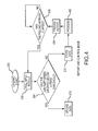
- an algorithm or routine may begin at step 200 after processor 4 receives an indication such as by a first sensor input that a triggering event 200 has occurred.
- the triggering event 200 is the initial touchdown of the aircraft upon landing.
- processor 4 then starts a polling timer to poll the input module 2 (step 202) and obtains the status of various sensors, for example, a second sensor input. This polled sensor data is placed in memory 5.
- the processor assesses the aircraft speed to determine whether it has dropped below a first threshold (step 204).
- the first threshold comprises a velocity at which the landing may be said to be complete, e.g., a landing threshold. In various embodiments, the first threshold comprises 10 knots (5.1 m/s). In various embodiments, the first threshold comprises the speed at which an aircraft may make a safe, no braking turn off a runway onto a taxiway.
- the polling timer continues to run and poll the sensors until the processor receives a sensor input indicating an ending event, for example, a third sensor input.
- the algorithm or routine may terminate with an ending event 250. For example, if the aircraft speed is less than or equal to the first threshold, in various embodiments, the speed indicates that the landing has completed. Consequently, the algorithm or routine proceeds to step 210, wherein any stored data, e.g., in memory 5, is uploaded to a ground station 14, and/or forwarded to an output device, and/or processed according to various calculations and algorithms for processing the collected data discussed further herein.
- the algorithm proceeds to step 206, wherein the processor stores the input data in memory 5.
- the processor 4 first processes the data according to various calculations and algorithms for processing the collected data discussed further herein before proceeding to step 206.
- the processor 4 stores the data in memory 5, then processes the data according to various calculations and algorithms for processing the collected data discussed further herein after proceeding to step 206.
- the processor does not process the data but stores it in memory 5, pending the completion of the landing.
- the processor never processes the data according to various calculations and algorithms for processing the collected data but rather transmits the data to a ground station 14 at which the data is processed according to these algorithms.
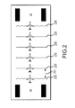
- step 208 the processor assesses whether a first polling interval has elapsed. If the interval has not elapsed, the workflow stops at step 208, until a first polling interval 201 has elapsed. If the first polling interval 201 (See Fig. 2 ) has elapsed, the processor returns to step 202 and polls the input module again.
- a first polling interval comprises a duration of time between instances 230 in which data from various sensors 18 is collected.
- a polling interval may be 1/10 of a sec (e.g., frequency of 10 Hz).
- a polling interval may be variable based on the aircraft velocity. In this manner, more frequent samples may be taken when the aircraft is traveling fast and less frequent samples may be taken when the aircraft is traveling slowly.
- the Nyquist sampling theorem may be implemented in conjunction with a pulse-width modulated antilock braking system and/or antiskid braking system and a variable sampling rate thus utilized to ameliorate the risks of input and/or brake signal aliasing.
- a runway traction estimation and reporting system may operate in a control and reporting mode rather than merely a reporting mode.
- an algorithm or routine may begin at step 200 after processor 4 receives an indication such as by a first sensor input that a triggering event 200 has occurred.
- the triggering event 200 is the initial touchdown of the aircraft upon landing.
- processor 4 then starts a polling timer to poll the input module 2 (step 202) and obtains the status of various sensors, for example, a second sensor input.
- This polled sensor data is placed in tangible, non-transitory memory 5.
- the processor assesses the aircraft speed to determine whether it has dropped below a first threshold (step 204).
- the first threshold comprises a velocity at which the landing may be said to be complete, e.g., a landing threshold.
- the first threshold comprises 10 knots (5.1 m/s).
- the first threshold comprises the speed at which an aircraft may make a safe, no braking turn off a runway onto a taxiway.
- the polling timer continues to run and poll the sensors until the processor receives a sensor input indicating an ending event, for example, a third sensor input.
- the algorithm or routine may terminate with an ending event 250. For example, if the aircraft speed is less than or equal to the first threshold, in various embodiments, the speed indicates that the landing has completed. Consequently, the algorithm or routine proceeds to step 210, wherein any stored data, e.g., in memory 5, is uploaded to a ground station 14, and/or forwarded to an output device, and/or processed according to various calculations and algorithms for processing the collected data discussed further herein.
- step 206 the processor stores the input data in memory 5.
- the processor 4 then processes the data (step 402) according to various calculations and algorithms for processing the collected data discussed further herein.
- the algorithm or routine proceeds to step 404 wherein the processor 4 produces an output based on the processing and sends the output to output module 6. This output is sent to an output device where it may be utilized according to the principles discussed herein.
- the output instructions may be sent to a human-readable display 10 for improving flight crew situational awareness, or may be sent to a brake controller 8, for improving braking performance, or may be sent to a transmitter 12, for relay to a ground station 14 or other aircraft (for example, directly to a receiver 20 of another aircraft).
- the output is not transmitted to an output device until the aircraft speed has dropped below the first threshold.
- step 208 the processor assesses whether a first polling interval has elapsed. If the interval has not elapsed, the workflow stops at step 208, until a first polling interval 201 has elapsed. If the first polling interval 201 (See Fig. 2 ) has elapsed, the processor returns to step 202 and polls the input module again.
- a first polling interval comprises a duration of time between instances 230 in which data from various sensors 18 is collected.
- a polling interval may be 1/10 or 2/20 of a sec (e.g., frequency of 10 Hz) (+/- 1/20 of a sec).
- a polling interval may be 1/400 or 2/800 of a sec (e.g., frequency of 400 Hz) (+/- 1/800 of a sec).
- a polling interval may be variable based on the aircraft velocity. In this manner, more frequent samples may be taken when the aircraft is traveling fast and less frequent samples may be taken when the aircraft is traveling slowly.
- the Nyquist sampling theorem may be implemented in conjunction with a pulse-width modulated antilock braking system and a variable sampling rate thus utilized to ameliorate the risks of input and/or brake signal aliasing.
- a runway traction control and reporting system may operate in a control only mode wherein the data is not transmitted via a transmitter 12, but is retained for internal use only.
- a runway traction estimation and reporting system may be switched between various operational modes, for example, reporting only, reporting and controlling, and/or controlling only (e.g., radio silent).
- a runway traction estimation and reporting system and various data collection and/or reporting algorithms, with reference to Fig. 2 , various calculations and algorithms for processing the collected data are disclosed.
- these algorithms may be performed in whole or part onboard the aircraft, for example by processor 4 in communication with tangible, non-transitory memory 5 (See Fig. 1 ).
- these algorithms may be performed in whole or part off board the aircraft, for example at ground station 14 comprising processor 26, where potentially greater computing power may be available.
- a history of wheel speed information is collected during a landing to iteratively estimate the friction properties of a runway.
- brake pressure and wheel speed measurements may be mapped to aircraft position data on the runway.
- wheel accelerations may be calculated in order to estimate wheel slip.
- the difference between a wheel's axle speed (e.g., aircraft speed) and a wheel's speed may comprise a wheel slip ratio whereby wheel slip may be determined.
- a brake controller may implement anti-skid functionality wherein peak wheel accelerations may be utilized to estimate wheel slip.
- correlation between events on the left side wheels of the aircraft and the right side wheels of the aircraft may be evaluated to further refine the boundaries of various runway areas having different traction estimates. For instance, because individual braked wheels provide data accurate to different portions of the runway, correlation between events on different sides of the aircraft, or on different wheels on the same side of the aircraft may permit further refinement of the boundaries of various runway areas having different traction estimates.
- runway location data and aircraft velocity date are obtained from at least one GPS unit.
- wheel rotation angle may be mapped to aircraft location measurements. In this manner, mapping of the brake control algorithm derived friction estimates will provide actual, average wheel slip data, whereby the friction estimates may be further refined.
- position of the thrust reversers and/or throttle position data may be incorporated into the algorithm, as a slip event during a time of thrust reversal likely indicates a lesser friction coefficient (lower runway traction), than a slip event during a time of forward thrust.
- a slip event during a time of thrust reversal likely indicates a lesser friction coefficient (lower runway traction), than a slip event during a time of forward thrust.
- an autobrake braking event for example, constant deceleration without any wheel skid events
- the presence of reverse thrust has the potential of producing a lower floor for detectable friction properties than would be produced without reverse thrust.
- the reverse thrust effect is less significant for the assessment of runway traction properties during a skid event.
- runway traction estimation and reporting systems described herein have been described in the context of aircraft applications; however, one will appreciate in light of the present disclosure, that the system described herein may be used in connection with various other vehicles, for example, cars, trucks, busses, trains, boats, and submersible vehicles, or any other vehicle or device, in which adaptation to environmental conditions is desirable, for example, automobile braking systems.
- a runway traction estimation and reporting system may include built-in testing logic.
- Built-in testing logic may comprise logic to perform certain tests (i.e., diagnostics) to determine whether the runway traction estimation and reporting systems is in a malfunctioning state.
- Built-in testing logic may reside in a sensor or a processor, such as processor 4, or a brake controller, such as brake controller 8, or any other component of a runway traction estimation and reporting system or other system in communication with the runway traction estimation and reporting system.
- Built-in testing logic may also include safety features that use aircraft status information to verify that the system is in condition for operation.
- non-transitory computer-readable medium should be construed to exclude only those types of transitory computer-readable media which were found in In re Nuijten, 500 F.3d 1346 (Fed. Cir. 2007) to fall outside the scope of patentable subject matter under 35 U.S.C. ⁇ 101, so long as and to the extent In re Nuijten remains binding authority in the U.S. federal courts and is not overruled by a future case or statute. Stated another way, the term “computer-readable medium” should be construed in a manner that is as broad as legally permissible.
- references to "various embodiments”, “one embodiment”, “an embodiment”, “an example embodiment”, etc. indicate that the embodiment described may include a particular feature, structure, or characteristic, but every embodiment may not necessarily include the particular feature, structure, or characteristic. Moreover, such phrases are not necessarily referring to the same embodiment. Further, when a particular feature, structure, or characteristic is described in connection with an embodiment, it is submitted that it is within the knowledge of one skilled in the art to affect such feature, structure, or characteristic in connection with other embodiments whether or not explicitly described. After reading the description, it will be apparent to one skilled in the relevant art(s) how to implement the disclosure in alternative embodiments.
Landscapes
- Engineering & Computer Science (AREA)
- Aviation & Aerospace Engineering (AREA)
- Physics & Mathematics (AREA)
- General Physics & Mathematics (AREA)
- Radar, Positioning & Navigation (AREA)
- Remote Sensing (AREA)
- Automation & Control Theory (AREA)
- Mechanical Engineering (AREA)
- Traffic Control Systems (AREA)
- Regulating Braking Force (AREA)
Applications Claiming Priority (1)
| Application Number | Priority Date | Filing Date | Title |
|---|---|---|---|
| US14/267,501 US9213334B2 (en) | 2014-05-01 | 2014-05-01 | Runway traction estimation and reporting system |
Publications (3)
| Publication Number | Publication Date |
|---|---|
| EP2940675A2 true EP2940675A2 (fr) | 2015-11-04 |
| EP2940675A3 EP2940675A3 (fr) | 2015-12-02 |
| EP2940675B1 EP2940675B1 (fr) | 2020-09-02 |
Family
ID=53385438
Family Applications (1)
| Application Number | Title | Priority Date | Filing Date |
|---|---|---|---|
| EP15165322.7A Active EP2940675B1 (fr) | 2014-05-01 | 2015-04-28 | Système d'estimation de traction de piste et d'établissement de rapports |
Country Status (2)
| Country | Link |
|---|---|
| US (1) | US9213334B2 (fr) |
| EP (1) | EP2940675B1 (fr) |
Cited By (2)
| Publication number | Priority date | Publication date | Assignee | Title |
|---|---|---|---|---|
| EP4082901A1 (fr) * | 2021-04-29 | 2022-11-02 | Airbus Operations Limited | Système et procédé pour un événement d'atterrissage d'aéronef |
| GB2617065A (en) * | 2022-03-25 | 2023-10-04 | Airbus Operations Ltd | Monitoring friction associated with a plurality of aircraft wheels |
Families Citing this family (4)
| Publication number | Priority date | Publication date | Assignee | Title |
|---|---|---|---|---|
| FR3044811B1 (fr) * | 2015-12-08 | 2018-01-12 | Airbus Operations | Procede et dispositif d'estimation d'une vitesse laterale et d'une position laterale d'un aeronef, lors d'une phase de roulage de l'aeronef. |
| FR3045563B1 (fr) * | 2015-12-18 | 2018-02-09 | Messier-Bugatti-Dowty | Procede et systeme de commande de freinage d’un aeronef equipe d’un systeme d’inversion de poussee |
| FR3093993B1 (fr) * | 2019-03-21 | 2021-02-26 | Safran Aircraft Engines | Procédé de contrôle du freinage des roues d’un avion et contrôleur de freinage de roues associé |
| US20220122469A1 (en) * | 2020-10-19 | 2022-04-21 | Hydro-Aire, Inc., A Subsidiary Of Crane Co. | Improved system for reporting aircraft runway conditions |
Family Cites Families (6)
| Publication number | Priority date | Publication date | Assignee | Title |
|---|---|---|---|---|
| US4482961A (en) * | 1981-09-18 | 1984-11-13 | The Boeing Company | Automatic control system for directional control of an aircraft during landing rollout |
| US8346455B2 (en) * | 2005-02-23 | 2013-01-01 | Zoltan Ivan Rado | Method and device for communicating true runway braking performance using data from the flight data management systems of landed aircraft |
| JP5174034B2 (ja) * | 2006-12-19 | 2013-04-03 | エンジニアード・アレスティング・システムズ・コーポレーション | 情報、詳しくは着陸航空機のパイロットに利用可能な滑走路状態に関する情報を改善又は増加するシステム及び方法 |
| FR2930669B1 (fr) * | 2008-04-24 | 2011-05-13 | Airbus France | Dispositif et procede de determination d'un etat de piste, aeronef comprenant un tel dispositif et systeme d'aide au pilotage exploitant cet etat de piste |
| FR2978736B1 (fr) * | 2011-08-01 | 2013-09-27 | Airbus Operations Sas | Dispositif et procede de determination d'un etat de piste, aeronef comprenant un tel dispositif et systeme d'aide au pilotage exploitant cet etat de piste |
| US9014881B2 (en) * | 2012-03-28 | 2015-04-21 | Louis DeGagne | System and method for dynamically determining runway stopping distance |
-
2014
- 2014-05-01 US US14/267,501 patent/US9213334B2/en active Active
-
2015
- 2015-04-28 EP EP15165322.7A patent/EP2940675B1/fr active Active
Non-Patent Citations (1)
| Title |
|---|
| None |
Cited By (4)
| Publication number | Priority date | Publication date | Assignee | Title |
|---|---|---|---|---|
| EP4082901A1 (fr) * | 2021-04-29 | 2022-11-02 | Airbus Operations Limited | Système et procédé pour un événement d'atterrissage d'aéronef |
| US12424112B2 (en) | 2021-04-29 | 2025-09-23 | Airbus Operations Limited | Aircraft landing event system and method |
| GB2617065A (en) * | 2022-03-25 | 2023-10-04 | Airbus Operations Ltd | Monitoring friction associated with a plurality of aircraft wheels |
| US12252273B2 (en) | 2022-03-25 | 2025-03-18 | Airbus Operations Limited | Monitoring friction associated with a plurality of aircraft wheels |
Also Published As
| Publication number | Publication date |
|---|---|
| EP2940675A3 (fr) | 2015-12-02 |
| US20150316929A1 (en) | 2015-11-05 |
| EP2940675B1 (fr) | 2020-09-02 |
| US9213334B2 (en) | 2015-12-15 |
Similar Documents
| Publication | Publication Date | Title |
|---|---|---|
| EP2940675B1 (fr) | Système d'estimation de traction de piste et d'établissement de rapports | |
| EP2964535B1 (fr) | Système d'alarme précoce de freinage d'aéronef | |
| JP5174034B2 (ja) | 情報、詳しくは着陸航空機のパイロットに利用可能な滑走路状態に関する情報を改善又は増加するシステム及び方法 | |
| CN102910284B (zh) | 跑道状态确定装置和方法、相关驾驶辅助系统和航空器 | |
| EP2800082A2 (fr) | Procédés et appareil permettant de déterminer et d'utiliser une condition de frottement de surface d'atterrissage | |
| US9257051B2 (en) | Aircraft avoidance method and drone provided with a system for implementing said method | |
| US8773289B2 (en) | Runway condition monitoring | |
| CN104554742B (zh) | 飞机停车性能显示和报警 | |
| EP2669194A2 (fr) | Systèmes et procédés pour afficher la distance de freinage d'un aéronef lors d'opérations de surface | |
| US8165735B2 (en) | Method and device for determining an aircraft landing delay margin | |
| EP3251107A1 (fr) | Surveillance d'accidents à distance et base de données répartie de diagnostic de véhicule | |
| EP3403892B1 (fr) | Évaluation des conditions de surface d'une piste | |
| JP2018167825A (ja) | 航空機質量決定のためのシステムおよび方法 | |
| EP3471081A1 (fr) | Analyse de performance d'atterrissage d'aéronef automatisé | |
| CN113955086B (zh) | 一种飞机空地状态的判断方法 | |
| US20220122469A1 (en) | Improved system for reporting aircraft runway conditions | |
| CN103884515A (zh) | 一种测量汽车防抱abs制动性能的仪表及检测方法 | |
| US20250347615A1 (en) | ESTIMATING A COEFFICIENT OF FRICTION (µ) OF RUNWAYS AND/OR TAXIWAYS | |
| US20250227448A1 (en) | Emergency data-source modalities for autonomous vehicles |
Legal Events
| Date | Code | Title | Description |
|---|---|---|---|
| PUAI | Public reference made under article 153(3) epc to a published international application that has entered the european phase |
Free format text: ORIGINAL CODE: 0009012 |
|
| AK | Designated contracting states |
Kind code of ref document: A2 Designated state(s): AL AT BE BG CH CY CZ DE DK EE ES FI FR GB GR HR HU IE IS IT LI LT LU LV MC MK MT NL NO PL PT RO RS SE SI SK SM TR |
|
| AX | Request for extension of the european patent |
Extension state: BA ME |
|
| PUAL | Search report despatched |
Free format text: ORIGINAL CODE: 0009013 |
|
| AK | Designated contracting states |
Kind code of ref document: A3 Designated state(s): AL AT BE BG CH CY CZ DE DK EE ES FI FR GB GR HR HU IE IS IT LI LT LU LV MC MK MT NL NO PL PT RO RS SE SI SK SM TR |
|
| AX | Request for extension of the european patent |
Extension state: BA ME |
|
| RIC1 | Information provided on ipc code assigned before grant |
Ipc: G08G 5/00 20060101AFI20151027BHEP Ipc: G08G 5/06 20060101ALI20151027BHEP |
|
| 17P | Request for examination filed |
Effective date: 20160602 |
|
| RBV | Designated contracting states (corrected) |
Designated state(s): AL AT BE BG CH CY CZ DE DK EE ES FI FR GB GR HR HU IE IS IT LI LT LU LV MC MK MT NL NO PL PT RO RS SE SI SK SM TR |
|
| STAA | Information on the status of an ep patent application or granted ep patent |
Free format text: STATUS: EXAMINATION IS IN PROGRESS |
|
| 17Q | First examination report despatched |
Effective date: 20180518 |
|
| GRAP | Despatch of communication of intention to grant a patent |
Free format text: ORIGINAL CODE: EPIDOSNIGR1 |
|
| STAA | Information on the status of an ep patent application or granted ep patent |
Free format text: STATUS: GRANT OF PATENT IS INTENDED |
|
| INTG | Intention to grant announced |
Effective date: 20200415 |
|
| GRAS | Grant fee paid |
Free format text: ORIGINAL CODE: EPIDOSNIGR3 |
|
| GRAA | (expected) grant |
Free format text: ORIGINAL CODE: 0009210 |
|
| STAA | Information on the status of an ep patent application or granted ep patent |
Free format text: STATUS: THE PATENT HAS BEEN GRANTED |
|
| AK | Designated contracting states |
Kind code of ref document: B1 Designated state(s): AL AT BE BG CH CY CZ DE DK EE ES FI FR GB GR HR HU IE IS IT LI LT LU LV MC MK MT NL NO PL PT RO RS SE SI SK SM TR |
|
| REG | Reference to a national code |
Ref country code: GB Ref legal event code: FG4D |
|
| REG | Reference to a national code |
Ref country code: AT Ref legal event code: REF Ref document number: 1309727 Country of ref document: AT Kind code of ref document: T Effective date: 20200915 Ref country code: CH Ref legal event code: EP |
|
| REG | Reference to a national code |
Ref country code: DE Ref legal event code: R096 Ref document number: 602015058247 Country of ref document: DE |
|
| REG | Reference to a national code |
Ref country code: IE Ref legal event code: FG4D |
|
| REG | Reference to a national code |
Ref country code: LT Ref legal event code: MG4D |
|
| PG25 | Lapsed in a contracting state [announced via postgrant information from national office to epo] |
Ref country code: LT Free format text: LAPSE BECAUSE OF FAILURE TO SUBMIT A TRANSLATION OF THE DESCRIPTION OR TO PAY THE FEE WITHIN THE PRESCRIBED TIME-LIMIT Effective date: 20200902 Ref country code: NO Free format text: LAPSE BECAUSE OF FAILURE TO SUBMIT A TRANSLATION OF THE DESCRIPTION OR TO PAY THE FEE WITHIN THE PRESCRIBED TIME-LIMIT Effective date: 20201202 Ref country code: GR Free format text: LAPSE BECAUSE OF FAILURE TO SUBMIT A TRANSLATION OF THE DESCRIPTION OR TO PAY THE FEE WITHIN THE PRESCRIBED TIME-LIMIT Effective date: 20201203 Ref country code: BG Free format text: LAPSE BECAUSE OF FAILURE TO SUBMIT A TRANSLATION OF THE DESCRIPTION OR TO PAY THE FEE WITHIN THE PRESCRIBED TIME-LIMIT Effective date: 20201202 Ref country code: SE Free format text: LAPSE BECAUSE OF FAILURE TO SUBMIT A TRANSLATION OF THE DESCRIPTION OR TO PAY THE FEE WITHIN THE PRESCRIBED TIME-LIMIT Effective date: 20200902 Ref country code: HR Free format text: LAPSE BECAUSE OF FAILURE TO SUBMIT A TRANSLATION OF THE DESCRIPTION OR TO PAY THE FEE WITHIN THE PRESCRIBED TIME-LIMIT Effective date: 20200902 Ref country code: FI Free format text: LAPSE BECAUSE OF FAILURE TO SUBMIT A TRANSLATION OF THE DESCRIPTION OR TO PAY THE FEE WITHIN THE PRESCRIBED TIME-LIMIT Effective date: 20200902 |
|
| REG | Reference to a national code |
Ref country code: NL Ref legal event code: MP Effective date: 20200902 |
|
| REG | Reference to a national code |
Ref country code: AT Ref legal event code: MK05 Ref document number: 1309727 Country of ref document: AT Kind code of ref document: T Effective date: 20200902 |
|
| PG25 | Lapsed in a contracting state [announced via postgrant information from national office to epo] |
Ref country code: RS Free format text: LAPSE BECAUSE OF FAILURE TO SUBMIT A TRANSLATION OF THE DESCRIPTION OR TO PAY THE FEE WITHIN THE PRESCRIBED TIME-LIMIT Effective date: 20200902 Ref country code: LV Free format text: LAPSE BECAUSE OF FAILURE TO SUBMIT A TRANSLATION OF THE DESCRIPTION OR TO PAY THE FEE WITHIN THE PRESCRIBED TIME-LIMIT Effective date: 20200902 Ref country code: PL Free format text: LAPSE BECAUSE OF FAILURE TO SUBMIT A TRANSLATION OF THE DESCRIPTION OR TO PAY THE FEE WITHIN THE PRESCRIBED TIME-LIMIT Effective date: 20200902 |
|
| PG25 | Lapsed in a contracting state [announced via postgrant information from national office to epo] |
Ref country code: CZ Free format text: LAPSE BECAUSE OF FAILURE TO SUBMIT A TRANSLATION OF THE DESCRIPTION OR TO PAY THE FEE WITHIN THE PRESCRIBED TIME-LIMIT Effective date: 20200902 Ref country code: NL Free format text: LAPSE BECAUSE OF FAILURE TO SUBMIT A TRANSLATION OF THE DESCRIPTION OR TO PAY THE FEE WITHIN THE PRESCRIBED TIME-LIMIT Effective date: 20200902 Ref country code: PT Free format text: LAPSE BECAUSE OF FAILURE TO SUBMIT A TRANSLATION OF THE DESCRIPTION OR TO PAY THE FEE WITHIN THE PRESCRIBED TIME-LIMIT Effective date: 20210104 Ref country code: SM Free format text: LAPSE BECAUSE OF FAILURE TO SUBMIT A TRANSLATION OF THE DESCRIPTION OR TO PAY THE FEE WITHIN THE PRESCRIBED TIME-LIMIT Effective date: 20200902 Ref country code: RO Free format text: LAPSE BECAUSE OF FAILURE TO SUBMIT A TRANSLATION OF THE DESCRIPTION OR TO PAY THE FEE WITHIN THE PRESCRIBED TIME-LIMIT Effective date: 20200902 Ref country code: EE Free format text: LAPSE BECAUSE OF FAILURE TO SUBMIT A TRANSLATION OF THE DESCRIPTION OR TO PAY THE FEE WITHIN THE PRESCRIBED TIME-LIMIT Effective date: 20200902 |
|
| PG25 | Lapsed in a contracting state [announced via postgrant information from national office to epo] |
Ref country code: ES Free format text: LAPSE BECAUSE OF FAILURE TO SUBMIT A TRANSLATION OF THE DESCRIPTION OR TO PAY THE FEE WITHIN THE PRESCRIBED TIME-LIMIT Effective date: 20200902 Ref country code: AL Free format text: LAPSE BECAUSE OF FAILURE TO SUBMIT A TRANSLATION OF THE DESCRIPTION OR TO PAY THE FEE WITHIN THE PRESCRIBED TIME-LIMIT Effective date: 20200902 Ref country code: AT Free format text: LAPSE BECAUSE OF FAILURE TO SUBMIT A TRANSLATION OF THE DESCRIPTION OR TO PAY THE FEE WITHIN THE PRESCRIBED TIME-LIMIT Effective date: 20200902 Ref country code: IS Free format text: LAPSE BECAUSE OF FAILURE TO SUBMIT A TRANSLATION OF THE DESCRIPTION OR TO PAY THE FEE WITHIN THE PRESCRIBED TIME-LIMIT Effective date: 20210102 |
|
| REG | Reference to a national code |
Ref country code: DE Ref legal event code: R097 Ref document number: 602015058247 Country of ref document: DE |
|
| PG25 | Lapsed in a contracting state [announced via postgrant information from national office to epo] |
Ref country code: SK Free format text: LAPSE BECAUSE OF FAILURE TO SUBMIT A TRANSLATION OF THE DESCRIPTION OR TO PAY THE FEE WITHIN THE PRESCRIBED TIME-LIMIT Effective date: 20200902 |
|
| PLBE | No opposition filed within time limit |
Free format text: ORIGINAL CODE: 0009261 |
|
| STAA | Information on the status of an ep patent application or granted ep patent |
Free format text: STATUS: NO OPPOSITION FILED WITHIN TIME LIMIT |
|
| 26N | No opposition filed |
Effective date: 20210603 |
|
| PG25 | Lapsed in a contracting state [announced via postgrant information from national office to epo] |
Ref country code: DK Free format text: LAPSE BECAUSE OF FAILURE TO SUBMIT A TRANSLATION OF THE DESCRIPTION OR TO PAY THE FEE WITHIN THE PRESCRIBED TIME-LIMIT Effective date: 20200902 Ref country code: SI Free format text: LAPSE BECAUSE OF FAILURE TO SUBMIT A TRANSLATION OF THE DESCRIPTION OR TO PAY THE FEE WITHIN THE PRESCRIBED TIME-LIMIT Effective date: 20200902 |
|
| PG25 | Lapsed in a contracting state [announced via postgrant information from national office to epo] |
Ref country code: IT Free format text: LAPSE BECAUSE OF FAILURE TO SUBMIT A TRANSLATION OF THE DESCRIPTION OR TO PAY THE FEE WITHIN THE PRESCRIBED TIME-LIMIT Effective date: 20200902 |
|
| REG | Reference to a national code |
Ref country code: DE Ref legal event code: R119 Ref document number: 602015058247 Country of ref document: DE |
|
| PG25 | Lapsed in a contracting state [announced via postgrant information from national office to epo] |
Ref country code: MC Free format text: LAPSE BECAUSE OF FAILURE TO SUBMIT A TRANSLATION OF THE DESCRIPTION OR TO PAY THE FEE WITHIN THE PRESCRIBED TIME-LIMIT Effective date: 20200902 |
|
| PG25 | Lapsed in a contracting state [announced via postgrant information from national office to epo] |
Ref country code: LU Free format text: LAPSE BECAUSE OF NON-PAYMENT OF DUE FEES Effective date: 20210428 |
|
| REG | Reference to a national code |
Ref country code: BE Ref legal event code: MM Effective date: 20210430 |
|
| PG25 | Lapsed in a contracting state [announced via postgrant information from national office to epo] |
Ref country code: DE Free format text: LAPSE BECAUSE OF NON-PAYMENT OF DUE FEES Effective date: 20211103 Ref country code: CH Free format text: LAPSE BECAUSE OF NON-PAYMENT OF DUE FEES Effective date: 20210430 Ref country code: LI Free format text: LAPSE BECAUSE OF NON-PAYMENT OF DUE FEES Effective date: 20210430 |
|
| PG25 | Lapsed in a contracting state [announced via postgrant information from national office to epo] |
Ref country code: IE Free format text: LAPSE BECAUSE OF NON-PAYMENT OF DUE FEES Effective date: 20210428 |
|
| PG25 | Lapsed in a contracting state [announced via postgrant information from national office to epo] |
Ref country code: IS Free format text: LAPSE BECAUSE OF FAILURE TO SUBMIT A TRANSLATION OF THE DESCRIPTION OR TO PAY THE FEE WITHIN THE PRESCRIBED TIME-LIMIT Effective date: 20210102 |
|
| PG25 | Lapsed in a contracting state [announced via postgrant information from national office to epo] |
Ref country code: BE Free format text: LAPSE BECAUSE OF NON-PAYMENT OF DUE FEES Effective date: 20210430 |
|
| PG25 | Lapsed in a contracting state [announced via postgrant information from national office to epo] |
Ref country code: HU Free format text: LAPSE BECAUSE OF FAILURE TO SUBMIT A TRANSLATION OF THE DESCRIPTION OR TO PAY THE FEE WITHIN THE PRESCRIBED TIME-LIMIT; INVALID AB INITIO Effective date: 20150428 |
|
| P01 | Opt-out of the competence of the unified patent court (upc) registered |
Effective date: 20230522 |
|
| PG25 | Lapsed in a contracting state [announced via postgrant information from national office to epo] |
Ref country code: CY Free format text: LAPSE BECAUSE OF FAILURE TO SUBMIT A TRANSLATION OF THE DESCRIPTION OR TO PAY THE FEE WITHIN THE PRESCRIBED TIME-LIMIT Effective date: 20200902 |
|
| PG25 | Lapsed in a contracting state [announced via postgrant information from national office to epo] |
Ref country code: MK Free format text: LAPSE BECAUSE OF FAILURE TO SUBMIT A TRANSLATION OF THE DESCRIPTION OR TO PAY THE FEE WITHIN THE PRESCRIBED TIME-LIMIT Effective date: 20200902 |
|
| PG25 | Lapsed in a contracting state [announced via postgrant information from national office to epo] |
Ref country code: TR Free format text: LAPSE BECAUSE OF FAILURE TO SUBMIT A TRANSLATION OF THE DESCRIPTION OR TO PAY THE FEE WITHIN THE PRESCRIBED TIME-LIMIT Effective date: 20200902 |
|
| PG25 | Lapsed in a contracting state [announced via postgrant information from national office to epo] |
Ref country code: MT Free format text: LAPSE BECAUSE OF FAILURE TO SUBMIT A TRANSLATION OF THE DESCRIPTION OR TO PAY THE FEE WITHIN THE PRESCRIBED TIME-LIMIT Effective date: 20200902 |
|
| PGFP | Annual fee paid to national office [announced via postgrant information from national office to epo] |
Ref country code: GB Payment date: 20260319 Year of fee payment: 12 |
|
| PGFP | Annual fee paid to national office [announced via postgrant information from national office to epo] |
Ref country code: FR Payment date: 20260320 Year of fee payment: 12 |