EP2940817A1 - Anschlussdose für leuchte für die öffentliche beleuchtung - Google Patents
Anschlussdose für leuchte für die öffentliche beleuchtung Download PDFInfo
- Publication number
- EP2940817A1 EP2940817A1 EP15165697.2A EP15165697A EP2940817A1 EP 2940817 A1 EP2940817 A1 EP 2940817A1 EP 15165697 A EP15165697 A EP 15165697A EP 2940817 A1 EP2940817 A1 EP 2940817A1
- Authority
- EP
- European Patent Office
- Prior art keywords
- phase
- conductors
- selector
- housing
- electrical
- Prior art date
- Legal status (The legal status is an assumption and is not a legal conclusion. Google has not performed a legal analysis and makes no representation as to the accuracy of the status listed.)
- Granted
Links
Images


Classifications
-
- H—ELECTRICITY
- H02—GENERATION; CONVERSION OR DISTRIBUTION OF ELECTRIC POWER
- H02G—INSTALLATION OF ELECTRIC CABLES OR LINES, OR OF COMBINED OPTICAL AND ELECTRIC CABLES OR LINES
- H02G3/00—Installations of electric cables or lines or protective tubing therefor in or on buildings, equivalent structures or vehicles
- H02G3/02—Details
- H02G3/08—Distribution boxes; Connection or junction boxes
- H02G3/18—Distribution boxes; Connection or junction boxes providing line outlets
Definitions
- Such a housing is intended to be installed in the lower part of a candelabrum, at an opening in the candelabrum and allowing access to the housing by an operator. From this housing, drivers walk in the mast to power the lantern, also called luminaire.
- the lantern includes a lamp, such as a discharge lamp or light-emitting diodes, also called LEDs or LEDs.
- This terminal block which can be of the type described in EP-A-0 629 021 , allows the connection between the four electrical conductors of a cable from the previous lamppost and the four conductors of a cable connected to the next lamppost.
- Electrical overcurrent protection is usually provided by a fuse holder, incorporating a fuse cartridge and mounted on a mounting bracket, such as a DIN rail 35.
- two conductors provide the connection between the terminal block and the fuse holder. They allow the transition from a three-phase network to a single-phase network and ensure the selection of the phase that will be used in the lantern. Finally, the two power supply conductors of the lantern are connected to the fuse holder.
- the conductors are usually screwed into the terminals of the terminal block and the fuse holder.
- the operator may be required to choose or modify, for each housing, the phase used for feeding the lantern. This requires disconnecting and reconnecting a conductor by screwing and unscrewing a screw. These different screwing operations are relatively restrictive, and require the use of one or more specific tools.
- the invention intends to remedy by proposing a housing including a reduced number of screwed connections and offering the possibility to the user to easily choose, without having recourse to a tool, the phase which he wishes connect to the power supply leads of the luminaire.
- This housing provides in particular the connection between the public lighting distribution circuit, called here primary circuit, and the supply circuit of the luminaire, called here secondary circuit.
- the subject of the invention is a box for connecting two secondary electrical conductors supplying a public lighting luminaire to two of the conductors of a three-phase primary electrical distribution network, this housing including a terminal block of connection to which the primary electrical conductors are connected.
- This housing is characterized in that it comprises a single selector for connecting or disconnecting, in one operation, a phase secondary electrical conductor to a primary electrical conductor selected from the three phase conductors of the three-phase primary electrical distribution network and secondary neutral electrical conductor to the primary neutral electrical conductor of this network.
- the selector of the invention allows the user to choose the phase to be connected, in addition to the neutral, to the supply conductors of the lantern.
- phase selection is easy and does not require the use of a tool.
- it is fast, since it can be performed in a single operation.
- the removal of the selector, relative to a fixed base of the housing allows to open the electrical circuit and to cut both the neutral and the phase.
- the luminaire is completely electrically isolated from the three-phase primary electrical distribution network.
- an overcurrent protection device such as a fuse
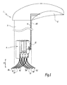
- the figure 1 represents a lamppost 1 comprising a lantern 2, also called fixture, and a mast 3, the lantern 2 being located at the top of the mast 3.
- the lamppost 1 also comprises a connection box 4 for electrically connecting the primary electrical conductors 5 of an electrical distribution network to secondary conductors 6 supplying the lantern 2 with electricity, from this housing.
- the lamppost 1 is powered by a three-phase primary electrical distribution network. More specifically, the primary conductors 5 comprise three primary phase conductors 51, 52 and 53 and a primary conductor of 5N neutral which supply the housing 4 with electricity and three primary conductors of phase 51 ', 52' and 53 'as well as 'a primary neutral conductor 5N' which feed another lamppost from the housing 4.
- the primary conductors 5 comprise three primary phase conductors 51, 52 and 53 and a primary conductor of 5N neutral which supply the housing 4 with electricity and three primary conductors of phase 51 ', 52' and 53 'as well as 'a primary neutral conductor 5N' which feed another lamppost from the housing 4.
- the secondary conductors 6 are two in number and comprise a phase conductor 6i and a neutral conductor 6N.
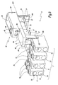
- connection box 4 comprises a connection terminal block 7 composed of four terminals 70, 71, 72 and 73 corresponding to the three phases of the network and to the neutral, and making it possible to ensure the continuity of the electrical distribution network.
- the neutral terminal 70 is at the extreme left on the figure 3 , while the terminals 71, 72 and 73 respectively corresponding to a first, a second and a third phase are aligned in this order from left to right.
- a connecting rod 8 is connected to the neutral terminal.
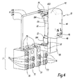
- the four terminals 70, 71, 72, 73 of the terminal block 7 of connection and the connection rod of the neutral 8 are covered by a shell 9 of insulating plastic material which is visible at the figure 2 .
- the shell 9 and the elements it contains constitute a base of the housing 4.
- the connection box 4 also comprises a selector 10.
- This selector 10 provides the electrical connection between some of the primary conductors 5 of the electrical distribution network, connected to the terminals 70, 71, 72, 73 of the terminal block 7, and the secondary conductors 6. 1.
- the selector 10 includes elastically deformable contact tabs 12 and 14 respectively provided on the front and rear of the selector 10.
- the selector 10 is designed to be mounted on the base of the housing 4, in one of three possible positions which make it possible to select, from among the three phases of the primary electrical distribution network, that which will be used for feeding the power supply. lantern, as can be seen from the explanations that follow.
- the contact tabs 12 are two in number and are made of an electrically conductive and elastically deformable material, in particular of metal.
- the two contact tabs 12 are formed by a single folded metal blade 16.
- the portions 12 converge towards one another from a central portion 162
- the two contact tabs 12 each comprise a fold 122 towards the outside, so that their lower ends 124 move slightly away from each other away from the part 162.
- the resilient tabs 12 form a clip and the constricted part of the tabs 12 defined between the folds 122 makes it possible to hold the selector 10 elastically in position on one of the terminals 71, 72, 73 of the terminal block 7, while the open ends 124 of the tabs 12 can easily fit the selector 10 on one of the terminals 71, 72, 73.
- the resilient tabs 14 have a shape comparable to that of the tabs 12. They are formed by a single folded metal blade 18 and have lower ends 144 bent outwardly to facilitate their mounting on a frame, a connecting rod 8 or an electrical contact. In practice, the tabs 14 are intended to be fitted on the rod 8.
- the metal part 16 defines, on its rear part a housing 20, made by bending the sheet metal strip in which the part 16 is formed.
- This housing 20 is of suitable dimensions to receive a first end, before, 21 of a fuse. 22.
- the housing 20 is delimited by a tab 164 which extends from the part 162 of the part 16.
- Fuse 22 is of standard size as commercially available. It is engaged, by its second end 23 in a housing 24 also obtained by bending a sheet metal strip which is, it, constituting a tongue 26. At the opposite of the housing 24, the tongue 26 is folded over it and itself constitutes a first secondary terminal 28 for connecting the secondary phase conductor.
- a second tab 30, equipped with a second secondary terminal 32 for connecting the secondary conductor of neutral comprises, on its rear part, an electrical connection strip 34 and a metal part 18 forming the rear legs 14.
- the connection rod 34 ensures, in addition, the maintenance in position of the rear metal part 18 relative to the tongue 30. It must therefore have sufficient mechanical strength not to break in case of successive casing and disassembly of the rear legs 14 on an electrical contact element, such as the rod connection 8.
- the metal part 16, the fuse 22, the first tongue 26 and the first secondary terminal 28 are electrically connected and constitute a first current flow circuit. Furthermore, the rear metal piece 18, the connecting rod 34, the second tongue 30 and the second secondary terminal 32 are electrically interconnected and form a second current flow circuit. Means are provided to prevent the first and the second circuit from coming into contact, in particular electrical insulation means such as a layer of synthetic material, as explained below.
- the secondary terminals 28 and 32 have a generally cubic shape and are formed by the folding of the two lateral ends of a sheet constituting the tongues 26 and 30, the two ends overlapping on an upper face of the cube.
- Two screws 36 and 38 are each mounted in a through tapping, pierced respectively on the upper face of the first 28 and the second 32 terminal. These screws 36 and 38 are adapted for clamping an electrical conductor against the lower face 40 of each terminal 28 and 32.
- the screws 36 and 38 provide both the mechanical attachment of an electrical conductor and its electrical connection with the tongue 26 or 30.
- the selector 10 also comprises a cover 42 made of insulating synthetic material. This cover 42 keeps in position the various conductive parts of the selector 10 and provides electrical insulation between phase and neutral and with the outside.
- the cover 42 comprises on its upper face 44 two orifices 46 and 48 for access to the screws 36 and 38.
- a front portion 50 of the cover 42 forms a reentrant shoulder and thus releases a vertical functional face 52 and directed forward.
- This functional face 52 is pierced with a first orifice 54 and a second orifice 56 respectively located vis-a-vis with the first 28 and the second 32 secondary terminal.
- These orifices 54 and 56 allow the passage of the electrical conductors 6i and 6N for connection to the selector 10, via the terminals 28 and 32.
- the terminals 70, 71, 72, 73 of the terminal block 7 are generally in the form of a right-hand block and are all identical. They may conform to the technical teaching of FR-A-2 621 744 . This is not required, however.
- Their upper face 74 is pierced with three orifices 75 aligned in a longitudinal direction and regularly spaced. Screws 76 are mounted in the two orifices 75 located furthest forward of each terminal 70, 71, 72, 73 of the terminal block 7.
- the orifice 75 situated at the rear of the terminal 70 most left, that is to say the neutral terminal is also equipped with a screw 76.
- terminals 70, 71, 72, 73 each have on their front face 77 two orifices 78 each allowing the connection of a primary conductor.
- These orifices 78 are of identical dimensions and are aligned in a direction up-down of the housing 4.
- each terminal 70, 71, 72, 73 comprises an orifice 79 situated on its rear face.
- the connecting rod 8 is mounted in the orifice 79 of the neutral terminal 70 and immobilized in this orifice, by clamping the corresponding fixing screw 76.
- the rod 8 is made from a round section wire and has a bend 82 at 90 °.
- the elbow 82 separates two branches 84 and 86 of the rod 8, the branch 84 being the one that is immobilized in the orifice 79 of the terminal 70.
- the branch 86 is adapted to be gripped by the rear legs 14 of the selector 10.
- the terminals 70, 71, 72, 73 are made of an electrically conductive material, in particular of brass, aluminum or steel.
- the plastic material shell 9 of the connection box 4 comprises on its front face 91 orifices 92 allowing the passage of the primary conductors. These orifices are eight in number and are distributed in two rows. They are of similar dimensions, regularly spaced and aligned with the orifices 78 located on the front faces of the terminals 70, 71, 72, 73.
- the shell 9 comprises, on its upper surface 93, orifices 94 allowing access to the screws 76.
- the upper face 93 has nine orifices 94, distributed in three rows. The first two rows each comprise four orifices and are located on the front of the upper face 93. These orifices 94 correspond to the orifices 75 drilled on the upper face 74 of the terminals 70, 71, 72, 73.
- the third row comprises only a single orifice 94 located on the left, and corresponding to the orifice 75 at the rear of the leftmost terminal 70.
- the upper face 93 of the plastic shell 9 comprises three pairs of two slots 96 adapted to pass the front lugs 12 of the selector 10.
- the shell 9 also comprises, on its upper face 93, three cavities 97, 98, 99, numbered from left to right, for receiving the fuse 22 attached to the selector 10 and the tabs 14 of the selector 10. These three cavities 97, 98, 99 are each located in alignment with a corresponding terminal 71, 72 or 73.
- the selector 10 is provided to be mounted, according to the user's choice, on a first, second or third phase, being engaged in one of the cavities 97, 98 and 99.
- the cavities 97, 98 and 99 form slots for selectively receiving the selector 10.
- the tabs 12 of the selector penetrate the slots 96 of one of the pairs of slots and enclose one of the terminals 71, 72 and 73. In however, regardless of the location 97, 98 or 99 used, the tabs 14 come to tighten on the branch 86, more or less close to the elbow 82.
- connection box 4 ensures the continuity of the three-phase primary electrical distribution network and the electrical connection between, on the one hand, the neutral and a phase of the three-phase primary electrical distribution network and, on the other hand, the conductors
- the primary conductors 5 are connected to the connection box 4 through the orifices 92.
- each of the primary conductors 5 is passed through an orifice 92 and the screws 76 make it possible to clamp these conductors. in the terminals 70, 71, 72 and 73 to ensure a permanent electrical connection even if the operator must subsequently intervene on the lantern 2 or change the fuse 22.
- the first row of screws 76 located at the front terminals 70, 71, 72, 73 make it possible to clamp the conductors 5N, 51, 52 and 53 inserted in the four orifices 78 upper of the front face 77 of the terminals 70, 71, 72, 73.
- the second ra Négée screw 76 located on the central portion of the terminals 70, 71, 72, 73 makes it possible to tighten the conductors 5N ', 51', 52 'and 53' in the four orifices 78 lower of the front face 77 of the terminals 70, 71 , 72, 73.
- the secondary conductors 6 are connected to the selector 10. Each secondary conductor 6 is passed through one of the orifices 54 or 56 and is fixed by a screw 36 or 38 respectively in the terminals 28 and 32. More precisely, the conductor 6i is engaged in the terminal 28 through the orifice 54, while the conductor 6N is engaged in the terminal 32 through the orifice 56.
- the connection of the conductors 6i and 6N on the selector 10 is also durable and not delivered in question, even in case of intervention on the lantern or fuse.
- the figures 1 and 3 represent the connection box 4 of the invention when the selector 10 is connected to the third phase of the network.
- the front lugs 12 of the selector 10 ensure electrical contact with the terminal 73, the rightmost.
- the character resilient legs 12 ensures a clean electrical connection between parts 16 and 73.
- the electric current is transmitted from terminal 7 to the tabs 12 and then passes through the fuse 22. It is then transmitted to the secondary electrical conductor 6i connected to the terminal 28 via the primary tongue 26.
- the first current flow circuit described above corresponds to the phase 3 and the fuse 22 is on this phase.
- the secondary electrical conductor 6i provides the electrical connection of phase 3 to the lantern 2 and can be called "63" in this case.
- the primary conductors 5N and 5N 'corresponding to the neutral of the distribution network are connected to the terminal 70, as previously described.
- the neutral is transmitted to the connecting rod 8 and then passes through the rear legs 14 of the selector 10 before being transmitted, via the connecting rod 34 and the secondary tongue 30, to the neutral secondary conductor 6N fixed to the terminal 32.
- the second current-passing circuit previously described corresponds systematically to the neutral.
- the selector 10 is fixed on the base of the connection box 4 and its two front lugs 12 are passed through two corresponding orifices 96.
- the fuse 22, as well as the rear lugs 14, are received in the orifice 99.
- the front lugs 12 and rear 14 provide the electrical contacts between the selector 10 and respectively the connection terminal 73 and the branch 86 of the connecting rod in neutral 8.
- the selector 10 may also be positioned in the same manner on the second connection terminal 71 from the left and the third connection terminal 72 from the left.
- the secondary conductor 6i routes phase 1 or phase 2 to the lantern and may be called "61" or "62" and the secondary neutral conductor remains connected to the branch 86, more or less close to the elbow 82 .
- the conductors 6i and 6N previously fixed in the terminals 28 and 32 are simultaneously and automatically connected to one of the phases and the neutral of the primary distribution network, without the need to use a screwdriver or other tool.
- the secondary conductors 6i and 6N are simultaneously and automatically isolated from the phase of the primary electrical distribution network and the neutral .
- the selector 10 comprises a printed circuit 602 on which are mounted various electrical components of the selector 10.
- the selector 10 comprises contact tabs 14 similar to the contact tabs of the first embodiment of the invention.
- the contact tabs 12 are replaced by contact tabs 604 comparable, located at the front.
- the rear contact tabs 14 and 604 are connected to the underside of the printed circuit 602 visible at the figure 7 .
- the fuse 22 is held in position by two fuse holder hooks 606 and 608 respectively immobilizing the front ends 21 and rear 23 of the fuse 22.
- a first connector 610 and a second connector 612 are also attached to the front end of the printed circuit 602.
- the first connector 610 is on the right while the second connector 612 is located. left according to the representation of the figure 6 .
- the printed circuit 602 electrically connects, on the one hand, the front contact tabs 604 to the fuse 22, the fuse 22 to the first connector 610, by a phase track 615, and on the other hand, the rear legs 14 to the second connector 612, by a neutral track.
- the phase track 615 has two branches 615a and 615b located on either side of the fuse 22.
- Two indicator lights are also connected to the upper face of the printed circuit board 602. 614 is called the first control and 616 the second. These indicators can be made by means of LEDs or other technology, and allow to visualize the presence of voltage on either side of the fuse 22.
- the first indicator 614 is mounted upstream of the fuse 22, between the neutral track 617 and the branch 615a of the phase track 615.
- the second indicator 616 is mounted downstream of the fuse 22, between the neutral track and the second branch 615b of the phase track.
- the first indicator 614 is illuminated when the selector 10 is supplied with electricity.
- the second light is illuminated when the output terminals 610 and 612 are powered, giving an indication of the state of the fuse.
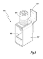
- the terminals 70, 71, 72, 73 are replaced by terminals similar to the terminal 800 of the figure 8 .
- This comprises a cage 802, formed of a sheet folded so as to form a closed volume cuboid. The two ends of the sheet overlap and comprise a threaded bore in which a screw 804 passes.
- the terminal 800 also comprises a support 806, made by a folded sheet part of which is parallel to the horizontal plane and housed in the cage 802. L the rear end of the support is folded vertically and serves to fix the terminal 800 to the connection box 4 and to ensure the electrical connections. In operation, this terminal 800 makes it possible to connect two primary conductors 5.
- a first conductor is inserted under the support 806, while a second conductor is inserted between the support 806 and the lower end of the screw 804.
- the clamping of the 804 screw clamps the two conductors 5 on either side 806.
- the support 806 is fixed relative to the connection box 4.
- the cage 802 is caused to perform a movement according to a vertical axis, upwards.
- a second fuse can be provided on the selector 10.
- the contact tabs 12 and 14, the terminals 70 to 73 and the rod 8 may be offset relative to each other, to the point that the connection of the conductor 6i to the one of the phases of the network is shifted in time relative to the connection of the conductor 6N to the neutral, even if these two connections result from the same mounting operation of the selector 10 on the base. The same goes for selector removal and disconnection.
Landscapes
- Engineering & Computer Science (AREA)
- Architecture (AREA)
- Civil Engineering (AREA)
- Structural Engineering (AREA)
- Fuses (AREA)
- Connections Arranged To Contact A Plurality Of Conductors (AREA)
Applications Claiming Priority (1)
| Application Number | Priority Date | Filing Date | Title |
|---|---|---|---|
| FR1453939A FR3020725B1 (fr) | 2014-04-30 | 2014-04-30 | Boitier de connexion pour luminaire d'eclairage public |
Publications (2)
| Publication Number | Publication Date |
|---|---|
| EP2940817A1 true EP2940817A1 (de) | 2015-11-04 |
| EP2940817B1 EP2940817B1 (de) | 2016-11-09 |
Family
ID=51168181
Family Applications (1)
| Application Number | Title | Priority Date | Filing Date |
|---|---|---|---|
| EP15165697.2A Active EP2940817B1 (de) | 2014-04-30 | 2015-04-29 | Anschlussdose für leuchte für die öffentliche beleuchtung |
Country Status (4)
| Country | Link |
|---|---|
| EP (1) | EP2940817B1 (de) |
| DK (1) | DK2940817T3 (de) |
| FR (1) | FR3020725B1 (de) |
| PT (1) | PT2940817T (de) |
Cited By (2)
| Publication number | Priority date | Publication date | Assignee | Title |
|---|---|---|---|---|
| DE102015007037B3 (de) * | 2015-06-02 | 2016-07-21 | Langmatz Gmbh | Sicherungskasten für Leitungsschutzsicherungen von Leuchten |
| BE1027301A1 (fr) | 2019-05-23 | 2020-12-15 | Teconex | Dispositif de protection et de raccordement d'un dispositif d'éclairage public |
Citations (3)
| Publication number | Priority date | Publication date | Assignee | Title |
|---|---|---|---|---|
| FR2621744A1 (fr) | 1987-10-07 | 1989-04-14 | Gen Export Ind Sa | Borne de connexion permettant le raccordement de plusieurs cables electriques de sections differentes entrant d'un meme cote de la borne et etant bloques dans des logements individuels superposes |
| EP0629021A1 (de) | 1993-06-11 | 1994-12-14 | Bruno Paul Claude Marcoz | Elektrische Anschlussleiste für elektrische Stromzuführungskabel |
| DE202006020166U1 (de) * | 2006-08-03 | 2008-03-13 | Lic Langmatz Gmbh | Sicherungskasten, insbesondere für Straßenleuchten |
-
2014
- 2014-04-30 FR FR1453939A patent/FR3020725B1/fr active Active
-
2015
- 2015-04-29 EP EP15165697.2A patent/EP2940817B1/de active Active
- 2015-04-29 PT PT151656972T patent/PT2940817T/pt unknown
- 2015-04-29 DK DK15165697.2T patent/DK2940817T3/en active
Patent Citations (3)
| Publication number | Priority date | Publication date | Assignee | Title |
|---|---|---|---|---|
| FR2621744A1 (fr) | 1987-10-07 | 1989-04-14 | Gen Export Ind Sa | Borne de connexion permettant le raccordement de plusieurs cables electriques de sections differentes entrant d'un meme cote de la borne et etant bloques dans des logements individuels superposes |
| EP0629021A1 (de) | 1993-06-11 | 1994-12-14 | Bruno Paul Claude Marcoz | Elektrische Anschlussleiste für elektrische Stromzuführungskabel |
| DE202006020166U1 (de) * | 2006-08-03 | 2008-03-13 | Lic Langmatz Gmbh | Sicherungskasten, insbesondere für Straßenleuchten |
Cited By (2)
| Publication number | Priority date | Publication date | Assignee | Title |
|---|---|---|---|---|
| DE102015007037B3 (de) * | 2015-06-02 | 2016-07-21 | Langmatz Gmbh | Sicherungskasten für Leitungsschutzsicherungen von Leuchten |
| BE1027301A1 (fr) | 2019-05-23 | 2020-12-15 | Teconex | Dispositif de protection et de raccordement d'un dispositif d'éclairage public |
Also Published As
| Publication number | Publication date |
|---|---|
| EP2940817B1 (de) | 2016-11-09 |
| PT2940817T (pt) | 2017-01-04 |
| FR3020725B1 (fr) | 2016-05-27 |
| DK2940817T3 (en) | 2017-01-30 |
| FR3020725A1 (fr) | 2015-11-06 |
Similar Documents
| Publication | Publication Date | Title |
|---|---|---|
| EP3323171B1 (de) | Isolator für eine schwenkbare elektrische verbindung | |
| FR2783365A1 (fr) | Dispositif de protection d'installations electriques contre les perturbations de l'alimentation | |
| EP2940817B1 (de) | Anschlussdose für leuchte für die öffentliche beleuchtung | |
| EP3544120A1 (de) | Elektrogerät und erdungsverfahren für ein solches gerät | |
| FR2715775A1 (fr) | Dispositif de raccordement électrique de type modulaire. | |
| EP0237388B1 (de) | Speise- oder Überbrückungsgerät für nebeneinander stehende elektrische Einrichtungen | |
| EP2996130B1 (de) | Schutzschalter | |
| FR2612565A1 (fr) | Unite de commande pour commandes electro-hydrauliques de soutenement | |
| EP2204886B1 (de) | Elektrischer Shunt | |
| FR2928041A1 (fr) | Prise d'alimentation electrique pour une goulotte ou analogue, utilisable individuellement ou en association. | |
| EP1432077A1 (de) | Modulares elektrisches Gerät mit geneigten Kopplungsflächen | |
| FR2562344A1 (fr) | Installation de distribution basse tension | |
| FR2955198A1 (fr) | Distributeur a coupe-circuit individuel | |
| FR2986104A1 (fr) | Appareil electrique au format modulaire | |
| EP1655806B1 (de) | Verbinder, Sammelschienenadapter mit Verbinder und Verteilergehäuse mit Sammelschienenadapter und Verbinder | |
| FR2807578A1 (fr) | Montant de chassis formant simultanement conduit de distribution et de repartition de l'energie electrique a differents niveaux de branchement d'appareillages | |
| EP0231310B1 (de) | Vorgefertigte elektrische anschliessvorrichtung zur verbindung an stromschienen | |
| FR3028356A1 (fr) | Borne de connexion electrique a vis imperdable | |
| EP1982344B1 (de) | Satz aus elektrischen steckverbindern und verfahren zur herstellung eines derartigen steckverbinders | |
| FR2786612A1 (fr) | Dispositif de raccordement electrique entre un systeme a barres et plusieurs cables conducteurs | |
| FR3001836A1 (fr) | Dispositif de fixation d'un appareillage electrique sur une paroi et procede de deconnexion associe | |
| FR2962600A1 (fr) | Dispositif de raccordement electrique | |
| FR2962861A1 (fr) | Dispositif de pontage configurable. | |
| FR3109029A1 (fr) | Dispositif et procédé de câblage d’une colonne électrique de remplacement | |
| FR2948823A1 (fr) | Connecteur, grille de fausse coupure comprenant un tel connecteur et coffret de raccordement equipe d'une telle grille |
Legal Events
| Date | Code | Title | Description |
|---|---|---|---|
| PUAI | Public reference made under article 153(3) epc to a published international application that has entered the european phase |
Free format text: ORIGINAL CODE: 0009012 |
|
| AK | Designated contracting states |
Kind code of ref document: A1 Designated state(s): AL AT BE BG CH CY CZ DE DK EE ES FI FR GB GR HR HU IE IS IT LI LT LU LV MC MK MT NL NO PL PT RO RS SE SI SK SM TR |
|
| AX | Request for extension of the european patent |
Extension state: BA ME |
|
| 17P | Request for examination filed |
Effective date: 20160404 |
|
| RBV | Designated contracting states (corrected) |
Designated state(s): AL AT BE BG CH CY CZ DE DK EE ES FI FR GB GR HR HU IE IS IT LI LT LU LV MC MK MT NL NO PL PT RO RS SE SI SK SM TR |
|
| GRAP | Despatch of communication of intention to grant a patent |
Free format text: ORIGINAL CODE: EPIDOSNIGR1 |
|
| INTG | Intention to grant announced |
Effective date: 20160607 |
|
| GRAS | Grant fee paid |
Free format text: ORIGINAL CODE: EPIDOSNIGR3 |
|
| GRAA | (expected) grant |
Free format text: ORIGINAL CODE: 0009210 |
|
| RAP1 | Party data changed (applicant data changed or rights of an application transferred) |
Owner name: LACROIX SOGEXI |
|
| AK | Designated contracting states |
Kind code of ref document: B1 Designated state(s): AL AT BE BG CH CY CZ DE DK EE ES FI FR GB GR HR HU IE IS IT LI LT LU LV MC MK MT NL NO PL PT RO RS SE SI SK SM TR |
|
| REG | Reference to a national code |
Ref country code: GB Ref legal event code: FG4D Free format text: NOT ENGLISH |
|
| REG | Reference to a national code |
Ref country code: AT Ref legal event code: REF Ref document number: 844702 Country of ref document: AT Kind code of ref document: T Effective date: 20161115 Ref country code: CH Ref legal event code: EP |
|
| REG | Reference to a national code |
Ref country code: CH Ref legal event code: NV Representative=s name: ARNOLD AND SIEDSMA AG, CH Ref country code: IE Ref legal event code: FG4D Free format text: LANGUAGE OF EP DOCUMENT: FRENCH |
|
| REG | Reference to a national code |
Ref country code: DE Ref legal event code: R096 Ref document number: 602015000666 Country of ref document: DE |
|
| REG | Reference to a national code |
Ref country code: DE Ref legal event code: R096 Ref document number: 602015000666 Country of ref document: DE |
|
| REG | Reference to a national code |
Ref country code: PT Ref legal event code: SC4A Ref document number: 2940817 Country of ref document: PT Date of ref document: 20170104 Kind code of ref document: T Free format text: AVAILABILITY OF NATIONAL TRANSLATION Effective date: 20161229 |
|
| REG | Reference to a national code |
Ref country code: DK Ref legal event code: T3 Effective date: 20170127 |
|
| PG25 | Lapsed in a contracting state [announced via postgrant information from national office to epo] |
Ref country code: LV Free format text: LAPSE BECAUSE OF FAILURE TO SUBMIT A TRANSLATION OF THE DESCRIPTION OR TO PAY THE FEE WITHIN THE PRESCRIBED TIME-LIMIT Effective date: 20161109 |
|
| REG | Reference to a national code |
Ref country code: LT Ref legal event code: MG4D |
|
| REG | Reference to a national code |
Ref country code: NL Ref legal event code: MP Effective date: 20161109 |
|
| REG | Reference to a national code |
Ref country code: FR Ref legal event code: PLFP Year of fee payment: 3 |
|
| REG | Reference to a national code |
Ref country code: AT Ref legal event code: MK05 Ref document number: 844702 Country of ref document: AT Kind code of ref document: T Effective date: 20161109 |
|
| PG25 | Lapsed in a contracting state [announced via postgrant information from national office to epo] |
Ref country code: LT Free format text: LAPSE BECAUSE OF FAILURE TO SUBMIT A TRANSLATION OF THE DESCRIPTION OR TO PAY THE FEE WITHIN THE PRESCRIBED TIME-LIMIT Effective date: 20161109 Ref country code: NL Free format text: LAPSE BECAUSE OF FAILURE TO SUBMIT A TRANSLATION OF THE DESCRIPTION OR TO PAY THE FEE WITHIN THE PRESCRIBED TIME-LIMIT Effective date: 20161109 Ref country code: SE Free format text: LAPSE BECAUSE OF FAILURE TO SUBMIT A TRANSLATION OF THE DESCRIPTION OR TO PAY THE FEE WITHIN THE PRESCRIBED TIME-LIMIT Effective date: 20161109 Ref country code: GR Free format text: LAPSE BECAUSE OF FAILURE TO SUBMIT A TRANSLATION OF THE DESCRIPTION OR TO PAY THE FEE WITHIN THE PRESCRIBED TIME-LIMIT Effective date: 20170210 Ref country code: NO Free format text: LAPSE BECAUSE OF FAILURE TO SUBMIT A TRANSLATION OF THE DESCRIPTION OR TO PAY THE FEE WITHIN THE PRESCRIBED TIME-LIMIT Effective date: 20170209 |
|
| PG25 | Lapsed in a contracting state [announced via postgrant information from national office to epo] |
Ref country code: IS Free format text: LAPSE BECAUSE OF FAILURE TO SUBMIT A TRANSLATION OF THE DESCRIPTION OR TO PAY THE FEE WITHIN THE PRESCRIBED TIME-LIMIT Effective date: 20170309 Ref country code: HR Free format text: LAPSE BECAUSE OF FAILURE TO SUBMIT A TRANSLATION OF THE DESCRIPTION OR TO PAY THE FEE WITHIN THE PRESCRIBED TIME-LIMIT Effective date: 20161109 Ref country code: FI Free format text: LAPSE BECAUSE OF FAILURE TO SUBMIT A TRANSLATION OF THE DESCRIPTION OR TO PAY THE FEE WITHIN THE PRESCRIBED TIME-LIMIT Effective date: 20161109 Ref country code: PL Free format text: LAPSE BECAUSE OF FAILURE TO SUBMIT A TRANSLATION OF THE DESCRIPTION OR TO PAY THE FEE WITHIN THE PRESCRIBED TIME-LIMIT Effective date: 20161109 Ref country code: ES Free format text: LAPSE BECAUSE OF FAILURE TO SUBMIT A TRANSLATION OF THE DESCRIPTION OR TO PAY THE FEE WITHIN THE PRESCRIBED TIME-LIMIT Effective date: 20161109 Ref country code: AT Free format text: LAPSE BECAUSE OF FAILURE TO SUBMIT A TRANSLATION OF THE DESCRIPTION OR TO PAY THE FEE WITHIN THE PRESCRIBED TIME-LIMIT Effective date: 20161109 Ref country code: RS Free format text: LAPSE BECAUSE OF FAILURE TO SUBMIT A TRANSLATION OF THE DESCRIPTION OR TO PAY THE FEE WITHIN THE PRESCRIBED TIME-LIMIT Effective date: 20161109 |
|
| PG25 | Lapsed in a contracting state [announced via postgrant information from national office to epo] |
Ref country code: SK Free format text: LAPSE BECAUSE OF FAILURE TO SUBMIT A TRANSLATION OF THE DESCRIPTION OR TO PAY THE FEE WITHIN THE PRESCRIBED TIME-LIMIT Effective date: 20161109 Ref country code: RO Free format text: LAPSE BECAUSE OF FAILURE TO SUBMIT A TRANSLATION OF THE DESCRIPTION OR TO PAY THE FEE WITHIN THE PRESCRIBED TIME-LIMIT Effective date: 20161109 Ref country code: CZ Free format text: LAPSE BECAUSE OF FAILURE TO SUBMIT A TRANSLATION OF THE DESCRIPTION OR TO PAY THE FEE WITHIN THE PRESCRIBED TIME-LIMIT Effective date: 20161109 Ref country code: EE Free format text: LAPSE BECAUSE OF FAILURE TO SUBMIT A TRANSLATION OF THE DESCRIPTION OR TO PAY THE FEE WITHIN THE PRESCRIBED TIME-LIMIT Effective date: 20161109 |
|
| REG | Reference to a national code |
Ref country code: DE Ref legal event code: R097 Ref document number: 602015000666 Country of ref document: DE |
|
| PG25 | Lapsed in a contracting state [announced via postgrant information from national office to epo] |
Ref country code: IT Free format text: LAPSE BECAUSE OF FAILURE TO SUBMIT A TRANSLATION OF THE DESCRIPTION OR TO PAY THE FEE WITHIN THE PRESCRIBED TIME-LIMIT Effective date: 20161109 Ref country code: BG Free format text: LAPSE BECAUSE OF FAILURE TO SUBMIT A TRANSLATION OF THE DESCRIPTION OR TO PAY THE FEE WITHIN THE PRESCRIBED TIME-LIMIT Effective date: 20170209 Ref country code: SM Free format text: LAPSE BECAUSE OF FAILURE TO SUBMIT A TRANSLATION OF THE DESCRIPTION OR TO PAY THE FEE WITHIN THE PRESCRIBED TIME-LIMIT Effective date: 20161109 |
|
| PLBE | No opposition filed within time limit |
Free format text: ORIGINAL CODE: 0009261 |
|
| STAA | Information on the status of an ep patent application or granted ep patent |
Free format text: STATUS: NO OPPOSITION FILED WITHIN TIME LIMIT |
|
| 26N | No opposition filed |
Effective date: 20170810 |
|
| PG25 | Lapsed in a contracting state [announced via postgrant information from national office to epo] |
Ref country code: SI Free format text: LAPSE BECAUSE OF FAILURE TO SUBMIT A TRANSLATION OF THE DESCRIPTION OR TO PAY THE FEE WITHIN THE PRESCRIBED TIME-LIMIT Effective date: 20161109 |
|
| REG | Reference to a national code |
Ref country code: IE Ref legal event code: MM4A |
|
| PG25 | Lapsed in a contracting state [announced via postgrant information from national office to epo] |
Ref country code: MC Free format text: LAPSE BECAUSE OF FAILURE TO SUBMIT A TRANSLATION OF THE DESCRIPTION OR TO PAY THE FEE WITHIN THE PRESCRIBED TIME-LIMIT Effective date: 20161109 |
|
| REG | Reference to a national code |
Ref country code: FR Ref legal event code: PLFP Year of fee payment: 4 |
|
| PG25 | Lapsed in a contracting state [announced via postgrant information from national office to epo] |
Ref country code: LU Free format text: LAPSE BECAUSE OF NON-PAYMENT OF DUE FEES Effective date: 20170429 |
|
| PG25 | Lapsed in a contracting state [announced via postgrant information from national office to epo] |
Ref country code: IE Free format text: LAPSE BECAUSE OF NON-PAYMENT OF DUE FEES Effective date: 20170429 |
|
| PG25 | Lapsed in a contracting state [announced via postgrant information from national office to epo] |
Ref country code: MT Free format text: LAPSE BECAUSE OF FAILURE TO SUBMIT A TRANSLATION OF THE DESCRIPTION OR TO PAY THE FEE WITHIN THE PRESCRIBED TIME-LIMIT Effective date: 20161109 |
|
| PG25 | Lapsed in a contracting state [announced via postgrant information from national office to epo] |
Ref country code: HU Free format text: LAPSE BECAUSE OF FAILURE TO SUBMIT A TRANSLATION OF THE DESCRIPTION OR TO PAY THE FEE WITHIN THE PRESCRIBED TIME-LIMIT; INVALID AB INITIO Effective date: 20150429 |
|
| PG25 | Lapsed in a contracting state [announced via postgrant information from national office to epo] |
Ref country code: CY Free format text: LAPSE BECAUSE OF FAILURE TO SUBMIT A TRANSLATION OF THE DESCRIPTION OR TO PAY THE FEE WITHIN THE PRESCRIBED TIME-LIMIT Effective date: 20161109 |
|
| PG25 | Lapsed in a contracting state [announced via postgrant information from national office to epo] |
Ref country code: MK Free format text: LAPSE BECAUSE OF FAILURE TO SUBMIT A TRANSLATION OF THE DESCRIPTION OR TO PAY THE FEE WITHIN THE PRESCRIBED TIME-LIMIT Effective date: 20161109 |
|
| GBPC | Gb: european patent ceased through non-payment of renewal fee |
Effective date: 20190429 |
|
| PG25 | Lapsed in a contracting state [announced via postgrant information from national office to epo] |
Ref country code: GB Free format text: LAPSE BECAUSE OF NON-PAYMENT OF DUE FEES Effective date: 20190429 |
|
| PG25 | Lapsed in a contracting state [announced via postgrant information from national office to epo] |
Ref country code: TR Free format text: LAPSE BECAUSE OF FAILURE TO SUBMIT A TRANSLATION OF THE DESCRIPTION OR TO PAY THE FEE WITHIN THE PRESCRIBED TIME-LIMIT Effective date: 20161109 |
|
| PG25 | Lapsed in a contracting state [announced via postgrant information from national office to epo] |
Ref country code: AL Free format text: LAPSE BECAUSE OF FAILURE TO SUBMIT A TRANSLATION OF THE DESCRIPTION OR TO PAY THE FEE WITHIN THE PRESCRIBED TIME-LIMIT Effective date: 20161109 |
|
| PGFP | Annual fee paid to national office [announced via postgrant information from national office to epo] |
Ref country code: PT Payment date: 20240318 Year of fee payment: 10 |
|
| PGFP | Annual fee paid to national office [announced via postgrant information from national office to epo] |
Ref country code: FR Payment date: 20240313 Year of fee payment: 10 Ref country code: DK Payment date: 20240326 Year of fee payment: 10 |
|
| PGFP | Annual fee paid to national office [announced via postgrant information from national office to epo] |
Ref country code: DE Payment date: 20240409 Year of fee payment: 10 |
|
| PGFP | Annual fee paid to national office [announced via postgrant information from national office to epo] |
Ref country code: CH Payment date: 20240501 Year of fee payment: 10 |
|
| PGFP | Annual fee paid to national office [announced via postgrant information from national office to epo] |
Ref country code: BE Payment date: 20240415 Year of fee payment: 10 |
|
| REG | Reference to a national code |
Ref country code: DE Ref legal event code: R119 Ref document number: 602015000666 Country of ref document: DE |
|
| REG | Reference to a national code |
Ref country code: DK Ref legal event code: EBP Effective date: 20250430 |
|
| REG | Reference to a national code |
Ref country code: CH Ref legal event code: H13 Free format text: ST27 STATUS EVENT CODE: U-0-0-H10-H13 (AS PROVIDED BY THE NATIONAL OFFICE) Effective date: 20251125 |
|
| PG25 | Lapsed in a contracting state [announced via postgrant information from national office to epo] |
Ref country code: PT Free format text: LAPSE BECAUSE OF NON-PAYMENT OF DUE FEES Effective date: 20251029 |
|
| REG | Reference to a national code |
Ref country code: BE Ref legal event code: MM Effective date: 20250430 |
|
| PG25 | Lapsed in a contracting state [announced via postgrant information from national office to epo] |
Ref country code: DE Free format text: LAPSE BECAUSE OF NON-PAYMENT OF DUE FEES Effective date: 20251104 |
|
| PG25 | Lapsed in a contracting state [announced via postgrant information from national office to epo] |
Ref country code: FR Free format text: LAPSE BECAUSE OF NON-PAYMENT OF DUE FEES Effective date: 20250430 |
|
| PG25 | Lapsed in a contracting state [announced via postgrant information from national office to epo] |
Ref country code: BE Free format text: LAPSE BECAUSE OF NON-PAYMENT OF DUE FEES Effective date: 20250430 |
|
| PG25 | Lapsed in a contracting state [announced via postgrant information from national office to epo] |
Ref country code: CH Free format text: LAPSE BECAUSE OF NON-PAYMENT OF DUE FEES Effective date: 20250430 |
|
| PG25 | Lapsed in a contracting state [announced via postgrant information from national office to epo] |
Ref country code: DK Free format text: LAPSE BECAUSE OF NON-PAYMENT OF DUE FEES Effective date: 20250430 |