EP2940840B1 - Ensemble rectificateur rotatif pour machine électrique - Google Patents
Ensemble rectificateur rotatif pour machine électrique Download PDFInfo
- Publication number
- EP2940840B1 EP2940840B1 EP15163056.3A EP15163056A EP2940840B1 EP 2940840 B1 EP2940840 B1 EP 2940840B1 EP 15163056 A EP15163056 A EP 15163056A EP 2940840 B1 EP2940840 B1 EP 2940840B1
- Authority
- EP
- European Patent Office
- Prior art keywords
- sleeve
- subassembly
- assembly
- rectifier
- bus bar
- Prior art date
- Legal status (The legal status is an assumption and is not a legal conclusion. Google has not performed a legal analysis and makes no representation as to the accuracy of the status listed.)
- Active
Links
Images

Classifications
-
- H—ELECTRICITY
- H02—GENERATION; CONVERSION OR DISTRIBUTION OF ELECTRIC POWER
- H02K—DYNAMO-ELECTRIC MACHINES
- H02K11/00—Structural association of dynamo-electric machines with electric components or with devices for shielding, monitoring or protection
- H02K11/04—Structural association of dynamo-electric machines with electric components or with devices for shielding, monitoring or protection for rectification
- H02K11/042—Rectifiers associated with rotating parts, e.g. rotor cores or rotary shafts
-
- H—ELECTRICITY
- H02—GENERATION; CONVERSION OR DISTRIBUTION OF ELECTRIC POWER
- H02K—DYNAMO-ELECTRIC MACHINES
- H02K19/00—Synchronous motors or generators
- H02K19/16—Synchronous generators
- H02K19/38—Structural association of synchronous generators with exciting machines
Definitions
- Electric machines such as electric motors and/or electric generators, may be used in the generation of electricity.
- generators typically include a generator rotor having main windings that are driven to rotate by a source of rotation, such as an electrical or mechanical machine, which for some aircraft may be a gas turbine engine.
- the generators initially generate alternating current (AC), which is rectified to generate direct current (DC) for DC components on the aircraft.
- AC alternating current
- DC direct current
- a rectifier assembly for placement within a rotating shaft of an electric machine assembly having a first machine providing an alternating current output and a second machine receiving a direct current input
- the rectifier assembly includes a rectifying subassembly having a bus bar electrically coupling with at least one of the direct current input of the second machine or the alternating current output of the first machine, and wherein the rectifier subassembly is configured to convert the alternating current output to the direct current input, and a non-conductive sleeve having an outer surface and an inner surface defining an interior having a keyway, and configured to axially receive the rectifying subassembly.
- the bus bar defines a key, which, when radially aligned with the keyway, provides for the keyed axial insertion of the rectifier subassembly within the sleeve, such that the rectifying subassembly is radially indexed within the sleeve to properly align the rectifying subassembly and the sleeve.
- Examples of the invention may be implemented in any environment using an electric motor regardless of whether the electric motor provides a driving force and/or generates electricity.
- an electric motor will be generally referred to as an electric machine, electric machine assembly, or similar language, which is meant to make clear that one or more stator/rotor combinations may be included in the machine. While this description is primarily directed toward an electric machine providing power generation, it is also applicable to an electric machine providing a driving force and/or an electric machine providing both a driving force and power generation. Further, while this description is primarily directed toward an aircraft environment, embodiments of the invention are applicable in any environment using an electric machine.
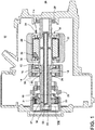
- FIG. 1 schematically illustrates an electrical machine assembly 10 comprising a first machine 12 having an exciter rotor 14 and an exciter stator 16, and a second machine 18 having a main machine rotor 20 and a main machine stator 22.
- the electrical machine assembly 10 is further shown comprising a permanent magnet generator (PMG) 19 having a PMG rotor 21 and a PMG stator 23.
- PMG permanent magnet generator
- At least one power connection is provided on the exterior of the electrical machine assembly 10 to provide for the transfer of electrical power to and from the electrical machine assembly 10. Power is transmitted by this power connection, shown as an electrical power cable 34, to the electrical load and may provide for a three phase with a ground reference output from the electrical machine assembly 10.
- the electrical machine assembly 10 further comprises a thermally conductive rotatable shaft 24 mechanically coupled to a source of axial rotation, which may be a gas turbine engine (not shown), about a common axis 26.
- the rotatable shaft 24 is supported by spaced bearings 28 and includes access openings 29 radially spaced about the shaft 24.
- the exciter rotor 14, main machine rotor 20, and PMG rotor 21 are mounted to the rotatable shaft 24 for rotation relative to the stators 16, 22, 23 which are rotationally fixed within the electrical machine assembly 10.
- the stators 16, 22, 23 may be mounted to any suitable part of a housing portion of the electrical machine assembly 10.
- the rotatable shaft 24 further comprises at least a hollow portion for enclosing a rectifier assembly 27, further comprising a sleeve or shaft tube 30, which is contemplated to be non-conducting and further houses a rectifier subassembly 32.
- the shaft tube 30 is rotationally coupled for co-rotating with the rotatable shaft 24 and the rectifier subassembly 32, and electrically insulates the rectifier subassembly 32 from the rotatable shaft 24. It is envisioned that the shaft tube 30 may comprise any suitable non-conductive material
- the exciter rotor 14 is electrically connected to the rectifier subassembly 32 by way of conductors 36 (schematically shown as dotted lines). Additionally, the rectifier subassembly 32 is electrically connected to the main windings 38 of the main machine rotor 20 by way of conductors 36.
- the PMG stator 23 may also be electrically connected to the exciter stator 16 by way of conductors 36.
- the shaft tube 30 has a substantially cylindrical structure having an inner surface 39 defining an interior 41, an outer surface 43, opposing open ends, and may further include four mounting connector openings 40 spaced radially near an end of the shaft tube 30.
- the shaft tube 30 is also shown having optional access openings 42, some of which may be radially aligned for accessing portions of the rectifier subassembly 32.
- the shaft tube 30 is shown further comprising optional keyed recesses, or anchor fastener openings 44, and extension tabs 92, at the axial end of the shaft tube 30, opposite of the mounting connector openings 40.
- the extension tabs 92 may provide proper axial spacing of the shaft tube 30 and/or rectifier assembly 27 within the rotatable shaft 24 and/or the electrical machine assembly 10, such that the shaft tube 30 cannot be axially over-inserted into the rotatable shaft 24.
- the extension tabs 92 may be radially keyed or indexed with the rotatable shaft 24 such that the shaft tube 30 may only be fully inserted when properly aligned with the rotatable shaft 24.
- the rectifier subassembly 32 comprises an axially extending conductive frame, shown as a ladder structure 48, having at least two elongated side elements 50 electrically coupled to each other via at least one conductive diode seat 68.
- the rectifier subassembly 32 also includes a plurality of conductive bus bars 52, 54 shown radially spaced about the rectifier subassembly 32 axis, illustrated as a single resilient conductive DC bus bar 52 and three conductive, yet malleable, output AC bus bars 54.
- the term "resilient,” in describing the DC bus bar 52 denotes at least a portion of the bus bar 52 configured to bias the bus bar 52 outwardly to the straight position shown.
- the DC bus bar 52 when flexed, will bias back towards the non-flexed position shown.
- the term “malleable” is used to describe the output AC bus bars 54 such that they may be easily altered, bent, or moveable as needed, and may be comprised from non-resilient wiring, or other suitable conductive material.
- the ladder structure 48 further comprises a set of axially spaced, forward-biased diodes 56 electrically coupling at least one of the AC bus bars 54 to the ladder structure 48.
- the ladder structure 48 is further electrically coupled to the DC bus bar 52.
- the ladder structure 48 may be made of any suitable conductive material, for example, aluminum.
- Each bus bar 52, 54 comprises a first end having terminal connectors 58 for securing the respective DC and AC bus bars 54, 52 to the respective first and second machines 12, 18 by way of conductors 36.
- the AC bus bars 54 receive the input AC voltage from the first machine and the DC bus bars 52 deliver the output DC voltage from the rectifier subassembly 32.
- the terminal connectors 58 may be integrally formed and/or conjoined with the first end of the bus bars 54, 52.
- a fastener such as a screw may be provided to aid in the mounting of the terminal connectors 58 to the first end of the bus bars 54, 52.
- non-mechanical fasteners such as welding or adhesive may also be used.
- the AC bus bars 54 are described as flexible, it is envisioned that the DC and AC bus bars 52, 54 may comprise any combination of flexible and/or inflexible conductive materials.
- the assembled components 48, 52, 54, 56 collectively define an axially extending, annular rectifier structure defining an axially extending interior. Alternate placement and configuration of the components 48, 52, 54, 56 are envisioned.
- the ladder structure 48 may also optionally comprise assembly anchors, shown as protrusions 46, which may be keyed to interact with the corresponding anchor fastener openings 44 of the shaft tube 30.
- the protrusions 46 and anchor fastener openings 44 are configured such that when the rectifier subassembly 32 is inserted within the shaft tube 30, the protrusions 46 are radial keyed to be axially received within the fastener openings 44.
- terminal connectors 58 and mounting connector openings 40 are configured such that, when the shaft tube 30 and the rectifier subassembly 32 are assembled and keyed based on the corresponding protrusions 46 and fastener openings 44, the connectors 58 are received by the openings 40 to provide for electrical coupling between the AC connectors 58 and the first machine 12, and the DC connectors 58 and the second machine 18.
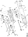
- FIG. 3 illustrates an exploded perspective view of the rectifier subassembly.
- the ladder structure 48 further comprises axially spaced and axially facing conductive diode seats 68 electrically coupling the side elements 50, wherein each seat 68 further comprises axially opposing first and second segment faces 62, 64, and an opening 66 that may extend through the seat 68.
- the first segment face 62 of each seat 68 may operate and or be configured for receiving the diode 56.
- Each diode 56 may additionally comprise an anode terminal 70 and a cathode terminal 72, configured in the direction of the diode 56 bias, wherein each terminal 70, 72 may be configurably coupled with any conductive surface coupling or suitable conductive mechanical or non-mechanical fasteners.
- the diodes 56 are shown having an anode terminal 70 configured to receive a mechanical fastener, such as a threaded screw 74, and a cathode terminal 70 configured to include a threaded screw 74 receivable by a screw base 76.
- the rectifier subassembly 32 may additionally comprise at least one non-conductive isolating segment 78 having at least one radially spaced guide channel, such as mounting connector 80, and configured to be placed adjacent to a second segment face 64 of a diode seat 68. In this sense, the isolating segment 78 may be supported by the diode seat 68, opposite of the diode 56.
- the mounting connector 80 may further be defined by restraining elements, shown as semi-circular restraining arms 82, configured such that the AC bus bars 54 extending axially along the isolating segment 78 may be receivably mounted by the mounting connector 80.
- the mounting connectors 80 may provide a suitable mounting coupling with the AC bus bars 54 wherein the mounting prevents damage to the bus bars 54, for instance, from vibrations or slight movements of the bus bars 54 relative to the mounting connector 80.
- the isolating segment 78 may further include an opening 66, similar in size, shape, and placement, to the opening of a correspondingly adjacent diode seat 68.
- each AC bus bar 54 may be electrically coupled with an anode terminal 70 of a diode 56 by, for example a threaded screw 74.
- the diode 56 is further electrically coupled, via the cathode terminal 72, to a first segment face 62 of a diode seat 68.
- the threaded extension of the cathode terminal 72 may be received through the opening 66 of the diode seat 68, and further received through the opening 66 of the isolating segment 78, wherein the threaded extension of the cathode terminal 72 may be, for instance, compressively fixed by a screw base 76.
- the assembling of the AC bus bar 54 and diode 56 closest to the bus bar 52, 54 end of the ladder structure 48 may also include an electrical coupling of the cathode terminal 72 of the diode 56 to the DC bus bar 52 in addition to the electrical coupling of the terminal 72 to the ladder structure 48, for instance, by receiving the threaded extension of the terminal 72 through a corresponding opening 66 of the DC bus bar 52.
- the ladder structure 48 and/or diode seat 68 may be keyed to mount the DC bus bar 52 in a certain configuration.
- the DC bus bar 52 may be electrically coupled to the ladder structure 48 at another mounting point.
- Alternative fixing methods and/or devices for assembling the above mentioned components are envisioned.
- the AC bus bars 54 extends axially along the rectifier subassembly 32 such that the diodes 56 may be electrically isolated from the ladder structure 48 and/or other diodes 56 by the mounting connectors 80 of the isolating segments 78. While substantially circular diodes 56, diode seats 68, and isolating segments 78 are illustrated, alternative shapes are envisioned. For example, circular or alternative shapes may include grooves or additional openings to allow for coolant and/or oil to transverse through the interior of, or about, the rectifier subassembly 32.
- the three AC bus bars 54 receive the respective three-phase AC output of the exciter rotor 14.
- the DC bus bar 52 is used for the transmission of the DC output to the second machine 18. Alternate arrangements and quantities of AC and DC bus bars 54, 52 are envisioned based on the needs and configuration of the electrical machine assembly 10.
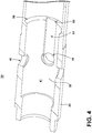
- FIG. 4 illustrates a perspective view of the shaft tube 30, taken along line 4-4 of FIG. 3 .
- the inner surface 39 and/or the interior 41 of the shaft tube 30 may further comprise at least a first portion of a radial segment defining a stop 59 extending from the inner surface 39, and at least another portion of the radial segment, different from the first, defining a keyway 60 without the stop 59.
- the keyway 60 further comprises an open top channel 61 extending axially along the inner surface 39 of the shaft tube 30 to the mounting connector opening 40.
- the stop 59 and keyway 60 are configured such that the stop 59 may prevent the axial insertion of components interacting with stop 59, but the keyway 60 will allow axial insertion of components that are radially aligned with, or radially indexed with the keyway 60. While the stop 59 is illustrated as a angled ridge on the inner surface 39 of the shaft tube 30, alternative geometric stop 59 configurations may be included, for example, an right angle ridge.
- the tube shaft 30 is configured to axially receive the rectifier subassembly 32.
- the resilient DC bus bar 52 may be flexed inwardly such that the bus bar 52 may be received within the interior 41 of the shaft tube 30 as the rectifier subassembly 32 is axially received by the tube 30. In this sense, the resiliency of the DC bus bar 52 biases the bus bar 52 outwardly along the inner surface 39 of the shaft tube 30.
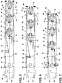
- the DC bus bar 52 may at least partially intersect the radial segment having the stop 59.
- the DC bus bar 52 is not radially aligned with the keyway 60 and the channel 61, physical interference between the bus bar 52 and/or the terminal connector 58 may prevent the improperly aligned subassembly 32 from being fully inserted into the shaft tube 30.
- DC bus bar 52 which, when radially aligned with the keyway 60 and the channel 61, provides for the axial insertion of the rectifier subassembly 32 within the shaft tube 30.
- the DC bus bar 52 may define a key such that the rectifying subassembly 32 is radially indexed, or keyed, within the shaft tube 30, to properly align the subassembly 32 and the tube 30. Due to the malleability of the AC bus bars 54, the AC bus bars 54 may not provide sufficient interference with the stop 59 during proper or improper alignment of the subassembly 32 and shaft tube 30, to prevent axial insertion of the of the subassembly 32 into shaft tube 30
- a properly keyed DC bus bar 52 and keyway 60 provide for the axial insertion of the rectifier sub assembly 32 past the stop 59, and the at least a resilient portion of the bus bar 52 continues to bias the bus bar 52 outwardly into the channel 61.
- the sidewalls of the open top channel 61 will prevent the subassembly 32 from axial rotation independent of the shaft tube 30, and thus, keep the subassembly 32 and shaft tube 30 properly aligned and/or keyed through the remainder of the axial insertion.
- FIG. 7 illustrates a cross-sectional view of the assembled rectifier assembly 27 wherein the rectifier subassembly 32 has been fully received within the shaft tube 30.
- the protrusions are received into the anchor fastener openings 44 to prevent over-insertion of the subassembly 32 into the shaft tube 30.
- the resiliency of the DC bus bar 52 will bias the terminal connector through the radially-aligned mounting connector opening 40 when the subassembly 32 has been fully inserted within the shaft tube 30, further preventing over insertion.
- the fully inserted rectifier subassembly 32 will also provide the AC bus bars 54 the proper level of insertion depth to, for example, manually biased the terminal connectors 58 of the AC bus bars 54 though their corresponding mounting connector openings 40.
- the rectifier subassembly 32 may be further axially secured to the shaft tube 30 when the terminal connectors 58 are secured to the first and second machines 12, 18, through the mounting connector openings 40.
- the rectifier subassembly 32 When fully assembled, that the rectifier subassembly 32 may be rotationally balanced, and thus allows for high speed rotation about the common axis 26.
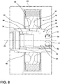
- FIG. 8 is an enlarged portion of the area labeled VIII of the electrical machine assembly of FIG. 1 , illustrating the rotatable shaft 24 and shaft tube 30 interface at the PMG rotor 21.
- the thermally conductive rotatable shaft 24 may define a rotating shaft interior 84, wherein at least a portion of the shaft tube 30 and rotating shaft interior 84 are in an overlapping relationship.
- the respective overlapping portions of the rotating shaft 24 and shaft tube 30 are shaped to define a thermally insulating gap 86 between the shaft 24 and the tube 30.
- the insulating gap 86 separates the thermally conductive rotatable shaft 24 from the shaft tube 30, which may be meltable when exposed to heat.
- the insulating gap 86 is an air gap, however alternative embodiments may include additional thermally insulating materials, such as a heat retardant foam, etc.
- the shaft tube 30 may be exposed to convection heat from the rotatable shaft 24, but will not be subjected to amounts of thermal conduction sufficient to melt the tube 30 when heat is applied to the rotatable shaft 24.
- the rotating shaft 24 and/or the shaft tube 30 may be configured to define and control the thermal insulation properties of the insulating gap 86.
- the diameter of the shaft tube 30, in at least an axially extending portion of the overlapping relationship may be increased or decreased to provide for, respectively more or less thermal insulation, relative to the diameter of the same portion of the rotatable shaft 24.
- the insulating gap 86 may be further defined by a recess 88 in the rotating shaft 24, however the insulating gap 86 may likewise be further defined by a recess in the shaft tube 30.
- the PMG rotor 21 is shown in direct heat contact, or heat coupled with the rotating shaft 24, and mounted such that the rotor 21 and shaft 24 will be rotationally coupled. As shown, the PMG rotor 21 may also be axially positioned on the rotating shaft 24 to be at least axially aligned with at least a portion of the overlapping relationship between the rotating shaft 24 and shaft tube 30. In this sense, the PMG rotor 21 overlies at least a portion of the insulating gap 86. In one example, the PMG rotor 21 may be mounted to the rotatable shaft 24 by one or more thermal welding points 90.
- embodiments may include welding paths, patches, or lines along the partial or full radial segment of the PMG rotor 21 and shaft 24 interface.
- the insulating gap 86 may be further configured and/or sized relative to the expected amount of heat generated by the welding points 90, which may be thermally conducted through the rotor 21 and/or the rotatable shaft 24, to prevent melting of the shaft tube 30.
- the rotatable shaft 24 is driven by the source of axial rotation.
- the rotation of the mounted PMG rotor 21 relative to the PMG stator 23 generates a current, which may be supplied to the exciter stator 16.
- the rotation of the mounted exciter rotor 14, adjacent to the electrified exciter stator 16, generates a three-phase AC current, which is delivered to three respective AC input bus bars 54 by the conductors 36 and terminal connectors 58.
- Each phase of the AC current is transmitted from the bus bar 54 to one diode 56.
- the diodes 56 are configured in a half bridge configuration and operate to provide rectification of the AC current to the DC current.
- the DC current from each diode 56 is transmitted through the ladder structure 48 to the DC bus bar 52, where the DC current is further transmitted by the terminal connectors 58 and conductors 36 into the main windings 38 of the main machine rotor 20.
- the rotation of the main machine rotor 20 about the main machine stator 22 generates the electricity that is used to power the generator load.
- the coolant may operate to cool any transient or steady-state temperature conditions that develop at the ladder structure 48, the diodes 56, and/or any of the bus bars 54, 52.
- the ladder structure 48 may be configured to receive heat generated by the operation of the diodes 56, and the coolant may dissipate heat from the ladder structure 48. Alternate coolant configurations are envisioned.
- one embodiment of the invention contemplates alternate configurations of forward or reverse-biased diode that may provide for full wave or half wave rectification.
- Another example of the invention contemplates using a self-contained oil system for cooling, or air for cooling.
- the shaft tube 30 may be made from either a conductive or non-conductive material to achieve further cost reduction.
- a different example of the invention may forgo the shaft tube 30 altogether and provide for the rectifier subassembly to be received directly into the rotatable shaft.
- any number of AC and or DC bus bars 52, 56 may be configured having at least a resilient portion biasing each resilient bus bar 52, 54 outwardly, and a corresponding number and alignment of indexed keyways 60 on the inner surface 39 of the tube shaft 30, such that the plurality of resilient bus bars 52, 54 define a plurality of keys, which provide for the keyed axial insertion of the rectifier subassembly 32 within the tube shaft 30.
- the bus bars 52, 54 may be keyed differently from each other, such that the subassembly 32 is radially indexed to properly align in only a single configuration, and/or each keyed bus bar 52, 54 may only be properly received by single keyway 60.
- One advantage that may be realized in the above embodiments is that the above described embodiments have superior weight and size advantages over the conventional type generator rectification systems. With the proposed rotating arrangement, current rectification can be achieved without the external space constraints of additional circuitry. Additionally, the construction and assembly of the rectifier will result in reduced maintenance downtime. Yet another advantage of the above embodiments is that the oil or coolant already present in the rotating shaft may be used to maintain the rectifier assembly, saving additional weight and size of a separate component. A further advantage of the above embodiments is that it reduces the risks of the diode electrically shorting to a metallic shaft. Moreover, due to the rotational balance of the rectifier assembly, a high peripheral speed can be achieved due to the reduced centrifugal forces of moving the assembly closer to the common axis of rotation. The higher peripheral speed results in a lower generator electromagnetic weight.
- the assembling of the rectifier assembly is that the keyed configuration of the resilient bus bar with the keyway provides for an effective method for proper alignment of the subassembly with the shaft tube, as the assembling will only complete when both components are oriented correctly, relative to each other. Furthermore, the resiliency of the bus bar, as aligned with the mounting connector openings provides for easy insertion of the subassembly within the tube to the proper depth, as the terminal connector will be biased through the opening with proper alignment at the correct insertion level.
- the configuration of the protrusions with the anchor fastener openings provide for and easy method of manual rotational alignment, as the alignment of the fastener openings with the protrusions will provide a proper key/keyway alignment, or knowledge that the alignment is off by 180 degrees. Additionally, the configuration of the anchor fastener openings and the protrusions also provide indication of the correct insertion levels of the subassembly within the shaft tube. The ease of assembly results in a reduction of assembly time and reduced maintenance costs.
- the insulating gap prevents melting of a meltable shaft tube when exposed to heat from the rotatable shaft, such as when the PMG rotor is welded to the rotatable shaft.
- the prevention of the shaft tube melting increases the reliability of the generator due to limiting the possibility of generator failure due to the partial melting of the tube, or harm that may come to the rectifier subassembly due to the melting. Additionally, the prevention of the shaft tube melting prevents the need for costly generator shaft repairs due to melting damage of the shaft tube, rectifier subassembly, or the rotatable shaft.
- the above described rectifier assembly has a decreased number of parts as the system will be able to provide rectified DC outputs with minimal power conversion equipment, making the complete system inherently more reliable. This results in a lower weight, smaller sized, increased performance, and increased reliability system. The lower number of parts and reduced maintenance will lead to a lower product costs and lower operating costs. Reduced weight and size correlate to competitive advantages during flight.
Landscapes
- Engineering & Computer Science (AREA)
- Power Engineering (AREA)
- Synchronous Machinery (AREA)
Claims (14)
- Ensemble redresseur (27) pour mise en place dans un arbre rotatif (24) d'un ensemble de machines électriques (10) ayant une première machine (12) fournissant une sortie de courant alternatif et une seconde machine (18) recevant une entrée de courant continu, l'ensemble redresseur comprenant :un sous-ensemble redresseur (32) ayant une barre omnibus (52, 54) se couplant électriquement à au moins l'une de l'entrée de courant continu de la seconde machine ou de la sortie de courant alternatif de la première machine, et dans lequel le sous-ensemble redresseur est configuré pour convertir la sortie de courant alternatif en entrée de courant continu ; etun manchon non conducteur (30) ayant une surface externe (43) et une surface interne définissant un intérieur (41), caractérisé en ce que le manchon présente une rainure de clavette (60), et est configuré pour recevoir axialement le sous-ensemble redresseur (32) ;dans lequel la barre omnibus (52, 54) définit une clavette (58) qui, lorsqu'elle est alignée radialement avec la rainure de clavette (60), permet l'insertion axiale clavetée du sous-ensemble redresseur (32) dans le manchon (30), de sorte que le sous-ensemble redresseur soit radialement inséré dans le manchon afin d'aligner convenablement le sous-ensemble redresseur et le manchon.
- Ensemble redresseur (27) selon la revendication 1, dans lequel la surface interne (39) comprend en outre au moins une première partie d'un segment radial définie par un arrêt (59) s'étendant de la surface interne (39), et au moins une seconde partie du segment radial, différente de la première, définit la rainure de clavette (60) sans l'arrêt.
- Ensemble redresseur (27) selon la revendication 2, comprenant en outre la barre omnibus (52, 54) qui, lorsqu'elle est reçue en partie par le manchon (30), coupe au moins en partie le segment radial, dans lequel l'interférence physique entre la barre omnibus et l'arrêt (59) empêche l'insertion complète dans le manchon d'un sous-ensemble incorrectement aligné.
- Ensemble redresseur (27) selon l'une quelconque des revendications précédentes, dans lequel la barre omnibus (52, 54) comprend en outre au moins une partie élastique configurée pour presser la barre omnibus (52, 54) vers l'extérieur le long de la surface interne (39) du manchon (30) lorsque le sous-ensemble (32) est inséré dans le manchon.
- Ensemble redresseur (27) selon la revendication 4, dans lequel la rainure de clavette (60) comprend en outre un canal supérieur ouvert (61) s'étendant axialement le long de la surface interne (39) du manchon (30), et dans lequel la barre omnibus (52, 54), lorsqu'elle est alignée radialement avec la rainure de clavette, est pressée dans le canal de sorte que ce canal empêche le sous-ensemble d'effectuer une rotation axiale indépendamment du manchon.
- Ensemble redresseur (27) selon l'une quelconque des revendications précédentes, comprenant en outre une pluralité de barres omnibus (52, 54), et une surface interne (39) définissant un intérieur ayant une pluralité correspondante de rainures de clavette (60), dans lequel les barres omnibus définissent une pluralité de clavettes (58), qui permettent une insertion axiale clavetée du sous-ensemble redresseur (32) dans le manchon (30), de sorte que le sous-ensemble redresseur soit radialement inséré dans le manchon afin d'aligner convenablement le sous-ensemble redresseur et le manchon.
- Ensemble redresseur (27) selon l'une quelconque des revendications précédentes, dans lequel le manchon (30) comprend en outre une ouverture (40) alignée radialement avec le couplage électrique de la barre omnibus élastique lorsque le sous-ensemble (32) est complètement inséré dans le manchon.
- Ensemble redresseur (27) selon l'une quelconque des revendications précédentes, dans lequel le manchon (30) comprend en outre au moins une patte d'extension sur au moins l'une d'une extrémité axiale du manchon, dans lequel la patte d'extension est configurée pour aligner axialement le manchon par rapport à l'arbre rotatif (24).
- Ensemble de machines électriques (10) comprenant :un arbre rotatif thermoconducteur (24) définissant un intérieur d'arbre ;une machine au moins en partie couplée à chaud à l'arbre rotatif ; etun ensemble redresseur (27) selon l'une quelconque des revendications précédentes, comprenant un manchon électriquement non conducteur (30) reçu dans l'intérieur de l'arbre et définissant un intérieur de manchon (41), et un sous-ensemble redresseur (32) reçu dans l'intérieur du manchon et convertissant le courant alternatif en courant continu ;dans lequel au moins une partie chevauchante de l'intérieur de l'arbre et du manchon sont conformés pour définir un intervalle thermo-isolant entre l'arbre et le manchon, de sorte que l'intervalle empêche une fusion de la partie du manchon lorsque de la chaleur est appliquée à l'arbre rotatif.
- Ensemble de machines électriques (10) selon la revendication 9, dans lequel la machine comprend en outre un aimant permanent couplé à chaud à l'arbre rotatif (24) et positionné axialement sur l'arbre rotatif de manière à être axialement aligné avec au moins une partie de l'intervalle.
- Ensemble de machines électriques (10) selon la revendication 10, dans lequel l'aimant permanent est soudé à l'arbre rotatif (24).
- Ensemble de machines électriques (10) selon la revendication 11, dans lequel l'intervalle est calibré par rapport à la chaleur générée par la soudure.
- Ensemble de machines électriques (10) selon l'une quelconque des revendications 9 à 12, dans lequel un diamètre de la partie du manchon (30) est calibré par rapport à un diamètre correspondant de la partie de l'arbre rotatif (24).
- Ensemble de machines électriques (10) selon l'une quelconque des revendications 9 à 13, dans lequel l'intervalle est en outre défini par une cavité dans au moins l'un de l'arbre rotatif (24) ou du manchon (30).
Applications Claiming Priority (1)
| Application Number | Priority Date | Filing Date | Title |
|---|---|---|---|
| US14/249,582 US9590477B2 (en) | 2014-04-10 | 2014-04-10 | Rotating rectifier assembly for electric machine |
Publications (3)
| Publication Number | Publication Date |
|---|---|
| EP2940840A2 EP2940840A2 (fr) | 2015-11-04 |
| EP2940840A3 EP2940840A3 (fr) | 2016-03-16 |
| EP2940840B1 true EP2940840B1 (fr) | 2017-07-12 |
Family
ID=52823528
Family Applications (1)
| Application Number | Title | Priority Date | Filing Date |
|---|---|---|---|
| EP15163056.3A Active EP2940840B1 (fr) | 2014-04-10 | 2015-04-09 | Ensemble rectificateur rotatif pour machine électrique |
Country Status (2)
| Country | Link |
|---|---|
| US (1) | US9590477B2 (fr) |
| EP (1) | EP2940840B1 (fr) |
Cited By (1)
| Publication number | Priority date | Publication date | Assignee | Title |
|---|---|---|---|---|
| EP4277091A1 (fr) * | 2022-05-10 | 2023-11-15 | Hamilton Sundstrand Corporation | Ensembles rotors de générateur |
Families Citing this family (5)
| Publication number | Priority date | Publication date | Assignee | Title |
|---|---|---|---|---|
| US10103604B2 (en) * | 2014-07-11 | 2018-10-16 | Ge Aviation Systems Llc | Rotating rectifier assembly for electric machine |
| EP3246527B1 (fr) * | 2016-05-18 | 2019-08-14 | Rolls-Royce Corporation | Générateur basse pression pour moteur de turbine à gaz |
| US11022042B2 (en) | 2016-08-29 | 2021-06-01 | Rolls-Royce North American Technologies Inc. | Aircraft having a gas turbine generator with power assist |
| US10879772B2 (en) | 2019-01-08 | 2020-12-29 | Hamilton Sundstrand Corporation | Rotating resistor assemblies |
| US11374456B2 (en) * | 2019-08-01 | 2022-06-28 | Hamilton Sundstrand Corporation | Generator main field connection |
Family Cites Families (24)
| Publication number | Priority date | Publication date | Assignee | Title |
|---|---|---|---|---|
| CA587388A (fr) * | 1957-03-12 | 1959-11-17 | Westinghouse Electric Corporation | Machine dynamoelectrique a courant alternatif |
| US3348127A (en) | 1964-08-20 | 1967-10-17 | Westinghouse Electric Corp | Support arrangement for diodes in a rotating rectifier exciter |
| GB1207308A (en) * | 1966-10-26 | 1970-09-30 | Rotax Ltd | Dynamo electric machines |
| GB1183291A (en) | 1968-02-14 | 1970-03-04 | Siemens Ag | Rectifier Arrangement |
| DE2508600A1 (de) | 1975-02-27 | 1976-09-09 | Siemens Ag | Gleichrichterbruecke |
| FR2444339A2 (fr) | 1978-02-02 | 1980-07-11 | Ducellier & Cie | Ensemble redresseur de courant |
| US4745315A (en) | 1983-12-15 | 1988-05-17 | General Electric Company | Brushless exciter with zero-gravity rectifier assembly |
| US4570094A (en) * | 1984-01-23 | 1986-02-11 | Sundstrand Corporation | Rotating rectifier assembly |
| US4628219A (en) * | 1985-09-13 | 1986-12-09 | Sundstrand Corporation | Rectifier assembly for mounting in a rotor |
| US4806814A (en) * | 1987-11-16 | 1989-02-21 | Sundstrand Corporation | Half-wave rotary rectifier assembly |
| US4959707A (en) * | 1989-04-14 | 1990-09-25 | Sundstrand Corporation | Rotating rectifier assembly |
| US5001376A (en) | 1990-02-12 | 1991-03-19 | Sundstrand Corporation | Rotating rectifier assembly |
| JPH0753402Y2 (ja) | 1993-02-19 | 1995-12-06 | 株式会社三ツ葉電機製作所 | ブラシ装置 |
| US5796196A (en) | 1996-08-26 | 1998-08-18 | Sundstrand Corporation | Adaptable rotating rectifier and suppression resistor assembly for two-pole, wound rotor of dynamoelectric machine |
| US6750572B2 (en) | 2002-03-01 | 2004-06-15 | Honeywell International, Inc. | Generator with improved lubrication and cooling system |
| US6903470B2 (en) | 2002-08-22 | 2005-06-07 | Honeywell International, Inc. | High speed generator with high-power rotating rectifiers cooling system |
| JP2005320086A (ja) | 2004-05-06 | 2005-11-17 | Duplo Seiko Corp | 給紙装置 |
| US7166943B2 (en) * | 2005-01-27 | 2007-01-23 | Hamilton Sundstrand Corporation | Rotating rectifier assembly with inner mounted diodes |
| US20060176720A1 (en) | 2005-02-04 | 2006-08-10 | Hamilton Sundstrand Corporation | Rotating rectifier with strap and diode assembly |
| JP4781709B2 (ja) * | 2005-05-11 | 2011-09-28 | 日本電産コパル株式会社 | モータ |
| US7586224B2 (en) | 2005-11-16 | 2009-09-08 | Hamilton Sundstrand Corporation | Rotating rectifier assembly |
| WO2008005169A2 (fr) | 2006-06-14 | 2008-01-10 | Board Of Regents, The University Of Texas System | Redresseur rotatif hautes performances pour appareils d'excitation de générateurs de courant alternatif et procédés associés |
| US7944100B2 (en) * | 2009-05-06 | 2011-05-17 | Hamilton Sundstrand Corporation | Generator rectifier assembly with ease of assembly features |
| US8030821B2 (en) * | 2009-05-06 | 2011-10-04 | Hamilton Sundstrand Corporation | Generator rotor with improved hollow shaft |
-
2014
- 2014-04-10 US US14/249,582 patent/US9590477B2/en active Active
-
2015
- 2015-04-09 EP EP15163056.3A patent/EP2940840B1/fr active Active
Non-Patent Citations (1)
| Title |
|---|
| None * |
Cited By (1)
| Publication number | Priority date | Publication date | Assignee | Title |
|---|---|---|---|---|
| EP4277091A1 (fr) * | 2022-05-10 | 2023-11-15 | Hamilton Sundstrand Corporation | Ensembles rotors de générateur |
Also Published As
| Publication number | Publication date |
|---|---|
| EP2940840A2 (fr) | 2015-11-04 |
| US20150295479A1 (en) | 2015-10-15 |
| EP2940840A3 (fr) | 2016-03-16 |
| US9590477B2 (en) | 2017-03-07 |
Similar Documents
| Publication | Publication Date | Title |
|---|---|---|
| US9369029B2 (en) | Rotating rectifier assembly for electric machine | |
| EP2940840B1 (fr) | Ensemble rectificateur rotatif pour machine électrique | |
| US10103604B2 (en) | Rotating rectifier assembly for electric machine | |
| US9490674B2 (en) | Rotating rectifier assembly for electric machine | |
| US9035507B2 (en) | Electric machine and rectifier assembly therefor | |
| US8063522B2 (en) | Generator rotor ground bushing | |
| US20150001972A1 (en) | Mechanically and electrically integrated module | |
| US6628024B1 (en) | Hermetically sealed feed-through assembly for gas turbine engine starter generators and related methods | |
| EP2793374B1 (fr) | Ensemble de terminal pour une machine électrique | |
| US6897584B2 (en) | High power terminal block assembly for generators and method of assembling and installing the same | |
| EP2662961A1 (fr) | Machine dynamo-électrique | |
| EP3599704A1 (fr) | Ensemble stator | |
| US4827165A (en) | Integrated diode package | |
| EP3223404B1 (fr) | Générateur de courant alternatif pour véhicule | |
| EP2793373A2 (fr) | Couvercle de bloc terminal | |
| US10250110B2 (en) | Fastening assembly for electric machine and rectifier therefor | |
| EP3291419B1 (fr) | Machine électrique tournante | |
| EP3866314B1 (fr) | Ensembles redresseurs rotatifs, générateurs ayant des ensembles redresseurs rotatifs et procédés de fabrication d'ensembles redresseurs rotatifs | |
| US20180172754A1 (en) | Rotating diode fault detection | |
| EP3261231B1 (fr) | Élément de connexion pour un alternateur d'une installation de production d'énergie électrique et alternateur comprenant ledit élément de connexion | |
| US12573909B2 (en) | Electrical machine having a lead retention assembly |
Legal Events
| Date | Code | Title | Description |
|---|---|---|---|
| PUAI | Public reference made under article 153(3) epc to a published international application that has entered the european phase |
Free format text: ORIGINAL CODE: 0009012 |
|
| AK | Designated contracting states |
Kind code of ref document: A2 Designated state(s): AL AT BE BG CH CY CZ DE DK EE ES FI FR GB GR HR HU IE IS IT LI LT LU LV MC MK MT NL NO PL PT RO RS SE SI SK SM TR |
|
| AX | Request for extension of the european patent |
Extension state: BA ME |
|
| PUAL | Search report despatched |
Free format text: ORIGINAL CODE: 0009013 |
|
| AK | Designated contracting states |
Kind code of ref document: A3 Designated state(s): AL AT BE BG CH CY CZ DE DK EE ES FI FR GB GR HR HU IE IS IT LI LT LU LV MC MK MT NL NO PL PT RO RS SE SI SK SM TR |
|
| AX | Request for extension of the european patent |
Extension state: BA ME |
|
| 17P | Request for examination filed |
Effective date: 20160916 |
|
| RBV | Designated contracting states (corrected) |
Designated state(s): AL AT BE BG CH CY CZ DE DK EE ES FI FR GB GR HR HU IE IS IT LI LT LU LV MC MK MT NL NO PL PT RO RS SE SI SK SM TR |
|
| RIC1 | Information provided on ipc code assigned before grant |
Ipc: H02K 11/042 20160101ALI20161212BHEP Ipc: H02K 11/04 20160101AFI20161212BHEP Ipc: H02K 19/38 20060101ALI20161212BHEP |
|
| GRAP | Despatch of communication of intention to grant a patent |
Free format text: ORIGINAL CODE: EPIDOSNIGR1 |
|
| INTG | Intention to grant announced |
Effective date: 20170303 |
|
| GRAS | Grant fee paid |
Free format text: ORIGINAL CODE: EPIDOSNIGR3 |
|
| GRAA | (expected) grant |
Free format text: ORIGINAL CODE: 0009210 |
|
| AK | Designated contracting states |
Kind code of ref document: B1 Designated state(s): AL AT BE BG CH CY CZ DE DK EE ES FI FR GB GR HR HU IE IS IT LI LT LU LV MC MK MT NL NO PL PT RO RS SE SI SK SM TR |
|
| REG | Reference to a national code |
Ref country code: GB Ref legal event code: FG4D |
|
| REG | Reference to a national code |
Ref country code: CH Ref legal event code: EP |
|
| REG | Reference to a national code |
Ref country code: AT Ref legal event code: REF Ref document number: 909189 Country of ref document: AT Kind code of ref document: T Effective date: 20170715 |
|
| REG | Reference to a national code |
Ref country code: IE Ref legal event code: FG4D |
|
| REG | Reference to a national code |
Ref country code: DE Ref legal event code: R096 Ref document number: 602015003474 Country of ref document: DE |
|
| REG | Reference to a national code |
Ref country code: NL Ref legal event code: MP Effective date: 20170712 |
|
| REG | Reference to a national code |
Ref country code: LT Ref legal event code: MG4D |
|
| REG | Reference to a national code |
Ref country code: AT Ref legal event code: MK05 Ref document number: 909189 Country of ref document: AT Kind code of ref document: T Effective date: 20170712 |
|
| PG25 | Lapsed in a contracting state [announced via postgrant information from national office to epo] |
Ref country code: SE Free format text: LAPSE BECAUSE OF FAILURE TO SUBMIT A TRANSLATION OF THE DESCRIPTION OR TO PAY THE FEE WITHIN THE PRESCRIBED TIME-LIMIT Effective date: 20170712 Ref country code: LT Free format text: LAPSE BECAUSE OF FAILURE TO SUBMIT A TRANSLATION OF THE DESCRIPTION OR TO PAY THE FEE WITHIN THE PRESCRIBED TIME-LIMIT Effective date: 20170712 Ref country code: AT Free format text: LAPSE BECAUSE OF FAILURE TO SUBMIT A TRANSLATION OF THE DESCRIPTION OR TO PAY THE FEE WITHIN THE PRESCRIBED TIME-LIMIT Effective date: 20170712 Ref country code: HR Free format text: LAPSE BECAUSE OF FAILURE TO SUBMIT A TRANSLATION OF THE DESCRIPTION OR TO PAY THE FEE WITHIN THE PRESCRIBED TIME-LIMIT Effective date: 20170712 Ref country code: NL Free format text: LAPSE BECAUSE OF FAILURE TO SUBMIT A TRANSLATION OF THE DESCRIPTION OR TO PAY THE FEE WITHIN THE PRESCRIBED TIME-LIMIT Effective date: 20170712 Ref country code: FI Free format text: LAPSE BECAUSE OF FAILURE TO SUBMIT A TRANSLATION OF THE DESCRIPTION OR TO PAY THE FEE WITHIN THE PRESCRIBED TIME-LIMIT Effective date: 20170712 Ref country code: NO Free format text: LAPSE BECAUSE OF FAILURE TO SUBMIT A TRANSLATION OF THE DESCRIPTION OR TO PAY THE FEE WITHIN THE PRESCRIBED TIME-LIMIT Effective date: 20171012 |
|
| PG25 | Lapsed in a contracting state [announced via postgrant information from national office to epo] |
Ref country code: LV Free format text: LAPSE BECAUSE OF FAILURE TO SUBMIT A TRANSLATION OF THE DESCRIPTION OR TO PAY THE FEE WITHIN THE PRESCRIBED TIME-LIMIT Effective date: 20170712 Ref country code: PL Free format text: LAPSE BECAUSE OF FAILURE TO SUBMIT A TRANSLATION OF THE DESCRIPTION OR TO PAY THE FEE WITHIN THE PRESCRIBED TIME-LIMIT Effective date: 20170712 Ref country code: BG Free format text: LAPSE BECAUSE OF FAILURE TO SUBMIT A TRANSLATION OF THE DESCRIPTION OR TO PAY THE FEE WITHIN THE PRESCRIBED TIME-LIMIT Effective date: 20171012 Ref country code: RS Free format text: LAPSE BECAUSE OF FAILURE TO SUBMIT A TRANSLATION OF THE DESCRIPTION OR TO PAY THE FEE WITHIN THE PRESCRIBED TIME-LIMIT Effective date: 20170712 Ref country code: ES Free format text: LAPSE BECAUSE OF FAILURE TO SUBMIT A TRANSLATION OF THE DESCRIPTION OR TO PAY THE FEE WITHIN THE PRESCRIBED TIME-LIMIT Effective date: 20170712 Ref country code: GR Free format text: LAPSE BECAUSE OF FAILURE TO SUBMIT A TRANSLATION OF THE DESCRIPTION OR TO PAY THE FEE WITHIN THE PRESCRIBED TIME-LIMIT Effective date: 20171013 Ref country code: IS Free format text: LAPSE BECAUSE OF FAILURE TO SUBMIT A TRANSLATION OF THE DESCRIPTION OR TO PAY THE FEE WITHIN THE PRESCRIBED TIME-LIMIT Effective date: 20171112 |
|
| REG | Reference to a national code |
Ref country code: DE Ref legal event code: R097 Ref document number: 602015003474 Country of ref document: DE |
|
| REG | Reference to a national code |
Ref country code: FR Ref legal event code: PLFP Year of fee payment: 4 |
|
| PG25 | Lapsed in a contracting state [announced via postgrant information from national office to epo] |
Ref country code: RO Free format text: LAPSE BECAUSE OF FAILURE TO SUBMIT A TRANSLATION OF THE DESCRIPTION OR TO PAY THE FEE WITHIN THE PRESCRIBED TIME-LIMIT Effective date: 20170712 Ref country code: CZ Free format text: LAPSE BECAUSE OF FAILURE TO SUBMIT A TRANSLATION OF THE DESCRIPTION OR TO PAY THE FEE WITHIN THE PRESCRIBED TIME-LIMIT Effective date: 20170712 Ref country code: DK Free format text: LAPSE BECAUSE OF FAILURE TO SUBMIT A TRANSLATION OF THE DESCRIPTION OR TO PAY THE FEE WITHIN THE PRESCRIBED TIME-LIMIT Effective date: 20170712 |
|
| PLBE | No opposition filed within time limit |
Free format text: ORIGINAL CODE: 0009261 |
|
| STAA | Information on the status of an ep patent application or granted ep patent |
Free format text: STATUS: NO OPPOSITION FILED WITHIN TIME LIMIT |
|
| PG25 | Lapsed in a contracting state [announced via postgrant information from national office to epo] |
Ref country code: EE Free format text: LAPSE BECAUSE OF FAILURE TO SUBMIT A TRANSLATION OF THE DESCRIPTION OR TO PAY THE FEE WITHIN THE PRESCRIBED TIME-LIMIT Effective date: 20170712 Ref country code: SM Free format text: LAPSE BECAUSE OF FAILURE TO SUBMIT A TRANSLATION OF THE DESCRIPTION OR TO PAY THE FEE WITHIN THE PRESCRIBED TIME-LIMIT Effective date: 20170712 Ref country code: SK Free format text: LAPSE BECAUSE OF FAILURE TO SUBMIT A TRANSLATION OF THE DESCRIPTION OR TO PAY THE FEE WITHIN THE PRESCRIBED TIME-LIMIT Effective date: 20170712 Ref country code: IT Free format text: LAPSE BECAUSE OF FAILURE TO SUBMIT A TRANSLATION OF THE DESCRIPTION OR TO PAY THE FEE WITHIN THE PRESCRIBED TIME-LIMIT Effective date: 20170712 |
|
| 26N | No opposition filed |
Effective date: 20180413 |
|
| PG25 | Lapsed in a contracting state [announced via postgrant information from national office to epo] |
Ref country code: SI Free format text: LAPSE BECAUSE OF FAILURE TO SUBMIT A TRANSLATION OF THE DESCRIPTION OR TO PAY THE FEE WITHIN THE PRESCRIBED TIME-LIMIT Effective date: 20170712 |
|
| PG25 | Lapsed in a contracting state [announced via postgrant information from national office to epo] |
Ref country code: MC Free format text: LAPSE BECAUSE OF FAILURE TO SUBMIT A TRANSLATION OF THE DESCRIPTION OR TO PAY THE FEE WITHIN THE PRESCRIBED TIME-LIMIT Effective date: 20170712 |
|
| REG | Reference to a national code |
Ref country code: CH Ref legal event code: PL |
|
| REG | Reference to a national code |
Ref country code: BE Ref legal event code: MM Effective date: 20180430 |
|
| REG | Reference to a national code |
Ref country code: IE Ref legal event code: MM4A |
|
| PG25 | Lapsed in a contracting state [announced via postgrant information from national office to epo] |
Ref country code: LU Free format text: LAPSE BECAUSE OF NON-PAYMENT OF DUE FEES Effective date: 20180409 |
|
| PG25 | Lapsed in a contracting state [announced via postgrant information from national office to epo] |
Ref country code: CH Free format text: LAPSE BECAUSE OF NON-PAYMENT OF DUE FEES Effective date: 20180430 Ref country code: BE Free format text: LAPSE BECAUSE OF NON-PAYMENT OF DUE FEES Effective date: 20180430 Ref country code: LI Free format text: LAPSE BECAUSE OF NON-PAYMENT OF DUE FEES Effective date: 20180430 |
|
| PG25 | Lapsed in a contracting state [announced via postgrant information from national office to epo] |
Ref country code: IE Free format text: LAPSE BECAUSE OF NON-PAYMENT OF DUE FEES Effective date: 20180409 |
|
| PG25 | Lapsed in a contracting state [announced via postgrant information from national office to epo] |
Ref country code: MT Free format text: LAPSE BECAUSE OF NON-PAYMENT OF DUE FEES Effective date: 20180409 |
|
| PG25 | Lapsed in a contracting state [announced via postgrant information from national office to epo] |
Ref country code: TR Free format text: LAPSE BECAUSE OF FAILURE TO SUBMIT A TRANSLATION OF THE DESCRIPTION OR TO PAY THE FEE WITHIN THE PRESCRIBED TIME-LIMIT Effective date: 20170712 |
|
| PG25 | Lapsed in a contracting state [announced via postgrant information from national office to epo] |
Ref country code: PT Free format text: LAPSE BECAUSE OF FAILURE TO SUBMIT A TRANSLATION OF THE DESCRIPTION OR TO PAY THE FEE WITHIN THE PRESCRIBED TIME-LIMIT Effective date: 20170712 |
|
| PG25 | Lapsed in a contracting state [announced via postgrant information from national office to epo] |
Ref country code: HU Free format text: LAPSE BECAUSE OF FAILURE TO SUBMIT A TRANSLATION OF THE DESCRIPTION OR TO PAY THE FEE WITHIN THE PRESCRIBED TIME-LIMIT; INVALID AB INITIO Effective date: 20150409 Ref country code: MK Free format text: LAPSE BECAUSE OF NON-PAYMENT OF DUE FEES Effective date: 20170712 Ref country code: CY Free format text: LAPSE BECAUSE OF FAILURE TO SUBMIT A TRANSLATION OF THE DESCRIPTION OR TO PAY THE FEE WITHIN THE PRESCRIBED TIME-LIMIT Effective date: 20170712 |
|
| PG25 | Lapsed in a contracting state [announced via postgrant information from national office to epo] |
Ref country code: AL Free format text: LAPSE BECAUSE OF FAILURE TO SUBMIT A TRANSLATION OF THE DESCRIPTION OR TO PAY THE FEE WITHIN THE PRESCRIBED TIME-LIMIT Effective date: 20170712 |
|
| P01 | Opt-out of the competence of the unified patent court (upc) registered |
Effective date: 20230414 |
|
| PGFP | Annual fee paid to national office [announced via postgrant information from national office to epo] |
Ref country code: DE Payment date: 20250319 Year of fee payment: 11 |
|
| PGFP | Annual fee paid to national office [announced via postgrant information from national office to epo] |
Ref country code: GB Payment date: 20260319 Year of fee payment: 12 |
|
| PGFP | Annual fee paid to national office [announced via postgrant information from national office to epo] |
Ref country code: FR Payment date: 20260320 Year of fee payment: 12 |