EP2940857B1 - Procédé de reproduction d'un moteur à courant continu sans brosse triphasé doté d'un émulateur de charge - Google Patents
Procédé de reproduction d'un moteur à courant continu sans brosse triphasé doté d'un émulateur de charge Download PDFInfo
- Publication number
- EP2940857B1 EP2940857B1 EP14166171.0A EP14166171A EP2940857B1 EP 2940857 B1 EP2940857 B1 EP 2940857B1 EP 14166171 A EP14166171 A EP 14166171A EP 2940857 B1 EP2940857 B1 EP 2940857B1
- Authority
- EP
- European Patent Office
- Prior art keywords
- emulator
- voltage
- state
- actuated
- motor
- Prior art date
- Legal status (The legal status is an assumption and is not a legal conclusion. Google has not performed a legal analysis and makes no representation as to the accuracy of the status listed.)
- Active
Links
Images




Classifications
-
- H—ELECTRICITY
- H02—GENERATION; CONVERSION OR DISTRIBUTION OF ELECTRIC POWER
- H02P—CONTROL OR REGULATION OF ELECTRIC MOTORS, ELECTRIC GENERATORS OR DYNAMO-ELECTRIC CONVERTERS; CONTROLLING TRANSFORMERS, REACTORS OR CHOKE COILS
- H02P27/00—Arrangements or methods for the control of AC motors characterised by the kind of supply voltage
- H02P27/04—Arrangements or methods for the control of AC motors characterised by the kind of supply voltage using variable-frequency supply voltage, e.g. inverter or converter supply voltage
- H02P27/06—Arrangements or methods for the control of AC motors characterised by the kind of supply voltage using variable-frequency supply voltage, e.g. inverter or converter supply voltage using DC to AC converters or inverters
- H02P27/08—Arrangements or methods for the control of AC motors characterised by the kind of supply voltage using variable-frequency supply voltage, e.g. inverter or converter supply voltage using DC to AC converters or inverters with pulse width modulation
-
- G—PHYSICS
- G05—CONTROLLING; REGULATING
- G05B—CONTROL OR REGULATING SYSTEMS IN GENERAL; FUNCTIONAL ELEMENTS OF SUCH SYSTEMS; MONITORING OR TESTING ARRANGEMENTS FOR SUCH SYSTEMS OR ELEMENTS
- G05B17/00—Systems involving the use of models or simulators of said systems
- G05B17/02—Systems involving the use of models or simulators of said systems electric
-
- H—ELECTRICITY
- H02—GENERATION; CONVERSION OR DISTRIBUTION OF ELECTRIC POWER
- H02P—CONTROL OR REGULATION OF ELECTRIC MOTORS, ELECTRIC GENERATORS OR DYNAMO-ELECTRIC CONVERTERS; CONTROLLING TRANSFORMERS, REACTORS OR CHOKE COILS
- H02P7/00—Arrangements for regulating or controlling the speed or torque of electric DC motors
- H02P7/06—Arrangements for regulating or controlling the speed or torque of electric DC motors for regulating or controlling an individual DC dynamo-electric motor by varying field or armature current
Definitions
- the invention relates to a method for simulating a three-phase brushless DC motor with a load emulator, wherein the load emulator is connected in three phases via its load terminals to the supply terminals of a motor controller and the load emulator has an emulator power electronics and an emulator control for controlling the emulator power electronics, wherein the emulator control of the motor control controlled input terminals and non-driven supply terminals determined, and the emulator power electronics is controlled by the emulator control so that in the controlled by the engine control input terminals of the emulator control based on a motor model calculated phase currents i emulate flow and on the not controlled by the engine control supply terminal one of the Emulator control based on a motor model calculated phase voltage v emulate is abandoned.
- the invention also relates to the emulator control of a load emulator configured to perform the previously described method of simulating a three-phase brushless DC motor in conjunction with emulator power electronics.
- the inverter of the motor controller works as an inverter, so it has as a source of energy to a DC voltage source and drives a load with AC voltage.
- a conventional method for simulating electrical loads with the aid of load emulators is shown in the article " E-Motoren: HIL test at full power ", written by Dr. Thomas Schulte, Nils Holthaus and Markus Plöger, published February 2010 in the journal” Automobil-Elektronik ".
- the load emulator is often realized in the form of a hardware-in-the-loop simulator, ie by a simulation computer, the mathematical models of the environment to be simulated - here the load in the form of brushless DC motor - calculated by numerical methods and in turn via a power electronic power amplifier -
- the emulator power electronics - has, which can be connected via the load terminals of the load emulator with the corresponding supply terminals of the engine control.
- Brushless DC motors work - unlike the name suggests - like permanently excited three-phase synchronous machines and are due to the brushless design low-wear and low maintenance.
- brushless DC motors are often used as drives of ancillaries, such.
- the emulator power electronics includes for acting on the supply terminals of the motor controller with corresponding electrical connection values voltage sources and power sources, which are usually connectable via decoupling inductances with the load terminals of the emulator power electronics.
- voltage sources and power sources which are usually connectable via decoupling inductances with the load terminals of the emulator power electronics.
- the invention is based on the object, the method described above for reproducing a three-phase brushless DC motor with a load emulator specify that a reliable commutation detection is ensured.
- the described detection of the transition of a feed terminal of the motor control from the non-driven state to the driven state is based on the consideration that in this transition, the affected feed connection is no longer quasi “disconnected" by open semiconductor switches in the motor control of the DC voltage source of the motor control, but by again closed semiconductor switch is connected to the voltage source of the motor controls and thus actively influenced the measured output voltage at the relevant supply terminal of the motor control and thus changed.
- the resulting disintegration of the measured voltage at the supply terminal and the phase voltage calculated by the motor model which is still performed under the assumption of the old, uncontrolled state, is a reliable indicator for a change in the switching state of the engine control and is used accordingly. Focusing on the supply connection of the engine control system, which is not activated at first, is therefore makes sense, because this supply connection on the next commutation event must necessarily go into the driven state, that is necessarily subject to a change of state.
- the emulator control controls the emulator power electronics in such a way that via the now driven by the motor control supply terminal j emulated by the emulator control phase current i emulate flows.
- the motor model encompassed by the emulator control undergoes a structure change with regard to the phase of the motor connected to the feed connection j, so that a calculation is adapted accordingly.
- the emulator control then switches a current source, in particular in the emulator power electronics, to the load connection concerned so that the calculated phase current can be set in the corresponding phase. Since the calculated phase current should cover the positive and negative sign range, the power source of the emulator power electronics also acts as a current sink. Therefore, in the following, the term of a power source, this always includes the functionality of a current sink.
- the voltage threshold value v TH is dimensioned such that it is greater than the maximum deviation between the calculated phase voltage v emulate in the phase of the non-controlled supply connection j, which is to be expected during a constant switching state of the motor control and thus of the emulator power electronics and the actually measured back voltage v inv (j) at the non-driven supply terminal j.
- the abovementioned deviations are to be expected primarily due to overshoots due to capacitive effects during voltage roll jumps.
- the voltage threshold v TH is selected as a fraction of the intermediate circuit voltage v DC_Link of the motor control, preferably less than half of the intermediate circuit voltage v DC_Link is selected, very preferably selected to be one fifth of the intermediate circuit voltage v DC_Link of the motor control becomes.
- the predetermined first time period t 1 is selected to be greater 1 than expected transient voltage distortion and / or that the predetermined first time period t is selected to be greater 1 than the latency of the voltage impression by the emulator control and emulator power electronics, preferably If the predetermined first time period t 1 should be greater than the largest of the two aforementioned time periods.
- the expected transient voltage distortions may be due to electromagnetic radiation, which in turn are dependent on the environment and construction and must be determined accordingly on site.
- the time t 1 is according to experience in the single-digit range of microseconds.
- This criterion is based on the finding that the current flows in a phase supplied with voltage via an initially controlled supply connection of the motor control, but that phase current ultimately comes to a standstill in the no longer activated state of the supply connection.
- the current-based commutation detection is preferably then applicable safely when there are large phase currents at a large load, at very low load and only very low phase currents there is a risk of misinterpretation.
- a particularly advantageous further development of the method is based on the finding that a sensible choice of the current threshold value depends on the rise time of the simulated current in the motor windings and thus on their simulated inductance.
- the said current threshold value i TH is defined around the - calculated - zero current. This current threshold must be set so that at a PWM duty cycle of 50% - this is the case with minimal current in the range of the zero current - the current ripple must not have a zero crossing between the two commutated and thus energized phases.
- the emulator power electronics are controlled such that the other connections k , l of the Emulator power electronics are set via an inductive decoupling to a predetermined voltage u intermediate .
- This voltage-based method for detecting the state transition of a supply connection from the driven to the non-activated state is based on the finding that a non-activated supply connection of the motor control, the is separated from the power supply of the motor control high impedance by open semiconductor switch in the motor control, without further to a predetermined voltage - here the voltage u intermediate - set. This is not possible with a still controlled supply connection, since this would be significantly influenced by the voltage source in the engine control. Due to the inductive decoupling a predetermined by the voltage source in the emulator power electronics voltage would have no lasting effect on the voltage at the supply terminals of the engine control.
- the predetermined voltage u intermediate in the region of the DC voltage switched by the motor control in particular equal to half the intermediate circuit voltage v DC_Link of the motor control.
- the predetermined second time period t 2 is dimensioned so large that a reliable distinction between a continuously driven supply connection and a previously activated, but no longer controlled supply connection is possible even at low load currents.
- t 2 is selected in the range of approximately 10 ⁇ s.
- both the first described current-based method for detecting the transition of a feed terminal of the motor control is implemented by the driven state in the non-driven state, as well as the described thereafter Stress-based methods for detecting such a transition.
- the emulator control detects the transition of a feed connection k of the motor control from the driven state to the non-driven state as it is current-based previously described.
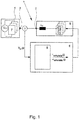
- Fig. 1 is initially shown a known from the prior art arrangement for carrying out a method for simulating a three-phase brushless DC motor with a Lastemulator 1, the load emulator 1 is three-phase connected via its load terminals 2 to the feed terminals 3 of a motor controller 4.
- the load emulator 1 has an emulator power electronics 5 and an emulator control 6 for controlling the emulator power electronics 5.
- the motor controller 4 itself also includes power electronics in the form of a three-phase inverter 7, which is supplied with power via a DC voltage source U DC and drives a three-phase alternating load via its supply terminals 3 by corresponding switching of the semiconductor switch encompassed by the inverter 7.
- the method provides that the emulator controller 6 determines the driven and not controlled by the engine control 4 supply terminals 3, wherein the emulator power electronics 5 is controlled by the emulator controller 6 so that in the driven by the motor controller 4 supply terminals 3 of the emulator controller 6 based
- the phase currents i emulate calculated by a motor model 8 flow, and the phase voltage calculated by the emulator control 6 on the basis of the motor model 8 flows to the supply connection not controlled by the motor control 4 v emulate is abandoned.
- the emulator power electronics 5 to accomplish this task both current sources I s and voltage sources U S , which can be switched according to the load terminals 2 of the emulator power electronics 5, which in the present case indirectly for each phase via a decoupling inductance L. d takes place.
- Fig. 2 the six occurring within an electrical rotation commutation transitions in a three-phase block-commutated brushless DC motor are shown, wherein the commutations are carried out in each case at an electrical angular distance of 60 °. It can be seen that the uncontrolled feed connection is maintained only in one commutation interval in one phase and then immediately reverts to the activated state; the phases are designated here by i 1 , i 2 and i 3 . Of the two controlled supply terminals 3 of the motor controller 4, a supply connection changes to the non-activated state, while the other controlled supply connection remains in the activated state. About the block commutated drive so a corresponding rotating field is generated in the brushless DC motor with which then a corresponding torque can be applied.
- Fig. 3 is the arrangement off Fig. 1 for performing the method according to the invention with the emulator control 6 set up according to the invention again shown in a higher degree of detail.
- a controller 9 is shown, which ensures that the predetermined phase currents are actually set at the load terminals 2 according to the specification from the emulator control 6.
- the respectively interesting phase current is measured back within the emulator power electronics 5 and fed to a control algorithm 10 for the purpose of forming a control difference.
- a modulator 11 assigns a predetermined voltage value or a predetermined current value to the respectively correct phase.
- the emulator control 6 is implemented in the illustrated embodiment on an FPGA board, on the "hard-wired" circuit structures ensure a particularly fast feasibility of the method described below.
- the output voltages v inv (j) which are measured at the supply terminals 3 of the motor controller 4, are read into the emulator control 6 and made available there, so they are genuine measured quantities.
- the calculated target values for calculated phase voltages v emulate (j) and for calculated phase currents i emulate (j) are output to the emulator power electronics 5 via the output interface 13.
- a state machine 14 is realized, with which commutation-related state changes at the supply connections 3 of the motor control 4 are detected.
- the state of the feed connection j is always referred to as S PH (j) , where the value 1 is for the non-activated state of the supply terminal j and the value 0 for the controlled state of the relevant supply terminal.
- a difference voltage v diff (j) is here to be expected in any case, since the measured output voltage v inv (j) changes in a switching operation of the motor controller 4 to a margin value of the motor control voltage U DC , while the calculated voltage v emulate (j) always still remains at a predetermined value within the DC voltage interval of the engine control, because the calculation within the emulator control 6 emanates from an uncontrolled state of the relevant feed terminal j .
- the method implemented in the emulator control 6 further provides that the emulator power electronics 5 is controlled by the emulator control 6 in such a way that via the feed connection j which is now controlled by the motor control 4 the phase current i emulate (j) calculated by the emulator control 6 flows.
- the calculated phase current i emulate (j) results from the calculation of the motor model 8 in the current calculation 15.
- the motor model 8 Based on the measured output voltages v inv of the motor strings driven by the motor control 4, the motor model 8 simulates the motor stator currents i emulate to be emulated. The voltage of the unpowered motor string then results from the measured output voltages v inv of the driven and thus energized motor strands or supply terminals 3 of the motor control 4 and from the inductive and magnetic properties of the simulated brushless DC motor. The magnetic properties are described by the induced voltages v emf in the three motor phases.
- the calculation of this voltage is based on the measured drive voltages of the driven and thus energized phases, on the current-dependent electrical inductive motor properties, the simulated motor currents and on the simulation of the magnetic properties, namely the induced reverse voltages v emf of the simulated motor.
- the magnetic properties of the brushless DC motor are described here with reference to a look-up table as a function of the electric motor angle. For this reason, in order to simulate the voltages measured at the motor control 4 in the context of an inverter calculation 16, a feedback of the electrical and magnetic properties from the current simulation 15 is required.
- the phase voltage v emulate calculated by the emulator control 6 on the basis of the motor model 8 essentially corresponds to the aforementioned simulated phase voltages of the motor control 4; it is set to a specific value of the intermediate circuit voltage v DC_Link , such as v DC_Link / 2, if two phases or two Supply terminals 3 of the motor controller 4 are not driven, which are only transient states, or all three phases or all three supply terminals 3 are driven.
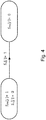
- the aforementioned state change is detected in the current-based case because the calculated phase current i emulate is detected as zero at the relevant load terminal 2 of the load emulator 1.
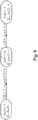
- Fig. 5 illustrated with another state diagram the peculiarity lies in the fact that the applied current-based detection of the state change is used when at the time of detecting the state transition of the feed terminal j of the motor controller 4 from the non-driven state to the driven state, the amounts of the calculated Phase currents i emulate the controlled supply terminals k, l are above a current threshold i TH .
- the criterion of the current threshold value i TH is intended to prevent a low-level load resulting from measurement inaccuracy, interference or otherwise resulting zero current from resulting in a misinterpretation of a feed connection 3.
- the transition from the in Fig. 5 the leftmost state to the middle transition state initially concerns the non-driven supply terminal (marked here with numeral 1) and the detection of the transition to the driven state.
- the transition from the middle transition state to the rightmost state then relates to the number 2 marked supply terminal of the motor controller 4 and the corresponding load terminal 2 of the load emulator 5, via which the current is measured to zero.
- Fig. 6 Alternatively, the voltage-based detection of the transition of a feed terminal k of the motor controller 4 from the driven state is shown in the non-driven state.
- the additional condition that the calculated current in the phases indicated by the numbers 2 and 3 is smaller than a current threshold value i TH will be discussed later.
- the emulator control 6 ensures in the middle state that the emulator power electronics and thus the connected motor control are put into a transitional state. It is namely ensured that the other terminals of the emulator power electronics, which are indicated in the formulas with the numbers 2 and 3, are set via an inductive decoupling to a predetermined voltage u intermediate .
- the transition of a feed terminal 3 of the motor controller 4 from the driven state to the non-driven state is detected voltage based exactly if, after the decay of the current through the relevant feed terminal 3 or the respective load terminal 2 of the emulator power electronics 5 the measured back from the emulator controller 6 on Supply terminal 3 over a predetermined second time period t 2 is equal to the predetermined voltage u intermediate .
- the phases designated by the numbers 2 and 3 have been set via the emulator power electronics 5 to in each case half the intermediate circuit voltage v DC_Link .
- the measured voltage v inv (3) of the third phase, which is still being controlled, and the third supply connection of the motor controller 4, which is still being controlled, will become intermediate from the discontinued voltage u intermediate , here as half the intermediate circuit voltage v DC link is selected differ because due to the inductive decoupling the voltage circuit through the motor controller 4 at the third supply terminal against the voltage specified by the emulator power electronics 5 prevails.
- Fig. 6 additionally illustrated criterion of the transition of the left to the middle state, namely i emulate (2,3) ⁇ i TH is additionally used here to "unlock" the use of the voltage-based state recognition.
- a decision is made between the use of the described voltage-based and the current-based state detection on the basis of the illustrated criterion with regard to the controlled phase currents, which of the two methods is used in the specific case.
- Current-based transient detection is used only with sufficiently large phase currents to avoid misinterpretation in current-based detection.
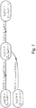
- Fig. 7 Another application option for voltage-based commutation detection is shown.
- the upper three states and transitions between these states are identical to the states and transitions as in Fig. 6 , New is the state shown below on the left, in which none of the three phases or none of the three supply terminals 3 of the motor control 4 is activated.
- one of the three phases is detected as the driven phase-here again the phase designated by the number 1 or the input terminal of the motor control 4 designated by number 1-via the auxiliary state variable S v .
- the other two phases remain so long in the de-energized state until they can be detected according to the respective auxiliary states S v as de-energized or driven.
- a third time period t 3 the value 1 correspond.
- the third time period t 3 is selected to be greater than the predetermined second time period t 2 .
- the time measurement for the determination of the third time period t 3 begins with the transition to the state that all auxiliary state variables S v have assumed the value 1.
- the predetermined third time period t 3 must be greater than the predetermined second time period t 2 , since otherwise the in Fig.
- the time value of t 3 should additionally be at least greater than the latency between a state change from a non-driven to a driven state or from a de-energized to a powered state and the impression of the corresponding voltage to be emulated as the predetermined second time t 2 .
Landscapes
- Engineering & Computer Science (AREA)
- Power Engineering (AREA)
- Physics & Mathematics (AREA)
- General Physics & Mathematics (AREA)
- Automation & Control Theory (AREA)
- Control Of Motors That Do Not Use Commutators (AREA)
- Control Of Ac Motors In General (AREA)
- Inverter Devices (AREA)
Claims (14)
- Procédé pour simuler un moteur à courant continu triphasé sans balai avec un émulateur de charge (1), dans lequel l'émulateur de charge (1) est raccordé en trois phases via ses raccords de charge (2) aux raccords d'alimentation (3) d'une unité (4) de commande de moteur et l'émulateur de charge (1) comporte une unité électronique (5) de puissance d'émulateur et une commande (6) d'émulateur pour la commande de l'unité électronique (5) de puissance d'émulateur, dans lequel la commande (6) d'émulateur détermine les raccords d'alimentation (3) pilotés par la commande (4) de moteur et les raccords d'alimentation (3) non pilotés, et l'unité électronique (5) de puissance d'émulateur est pilotée par la commande (6) d'émulateur de sorte que des courants de phase iemulate calculés par la commande (6) d'émulateur sur la base d'un modèle (8) de moteur circulent dans les raccords d'alimentation (3) pilotés par la commande (4) de moteur et qu'une tension de phase vemulate calculée par la commande d'émulateur sur la base d'une modèle (8) de moteur soit appliquée sur le raccord (3) d'alimentation non piloté par la commande (4) de moteur,
caractérisé en ce que
la transition d'un raccord d'alimentation j de la commande (4) de moteur de l'état non piloté SPH(j)=1 à l'état piloté SPH(j)=0 est identifié si la valeur de la tension différentielle vdiff(j) entre la tension de sortie vinv(j) mesurée au raccord d'alimentation j de la commande (4) de moteur et la tension de phase vemulate (j) calculée pour une première période de temps prédéterminée t1 est supérieure à une valeur seuil de tension prédéterminée vTH,
et que, après l'identification de la transition d'état du raccord d'alimentation j de la commande de moteur de l'état non piloté SPH(j)=1 à l'état piloté SPH(j)=0, la commande (6) d'émulateur commande l'unité électronique (5) de puissance d'émulateur de manière à ce que le courant de phase iemulate (j) calculé par la commande (6) d'émulateur circule à travers le raccord d'alimentation j à présent pilotée par la commande (4) de moteur. - Procédé selon la revendication 1, caractérisé en ce que la valeur seuil de tension vTH est dimensionnée de manière à être supérieure à l'écart maximale entre la tension de phase calculée vemulate(j) dans la phase du raccord d'alimentation non piloté j et la tension vinv(j) effectivement mesurée au raccord non piloté j, prévisible durant un état de commutation constant de la commande (4) de moteur, et donc de l'unité électronique (5) de puissance d'émulateur, en particulier, qu'un cinquième de la tension de circuit intermédiaire vDC_Link de la commande (4) de moteur est choisi pour la valeur seuil de tension vTH.
- Procédé selon la revendication 1 ou 2, caractérisé en ce que la première période de temps prédéterminée t1 est choisie plus longue que la durée des distorsions de tension transitoires prévisibles, en particulier des distorsions de tension occasionnées par l'irradiation électromagnétique, qui dépendre de l'environnement et du montage, et/ou que la première période de temps prédéterminée t1 est choisie plus longue que la latence de l'allocation de tension par la commande (6) d'émulateur et l'unité électronique (5) de puissance d'émulateur, dans lequel en particulier la première période de temps t1 est choisie dans la plage à un chiffre de microsecondes.
- Procédé selon l'une des revendications 1 à3, caractérisé en ce que la transition d'un raccord d'alimentation k de la commande (4) de moteur de l'état piloté SPH(k)=0 à l'état non piloté SPH(k)=1 est identifié sur la base du courant si le courant de phase calculé iemulate est détecté en tant que nul au raccord de charge k de l'émulateur (1) de charge, et donc au raccord d'alimentation k correspondant.
- Procédé selon la revendication 4, caractérisé en ce que l'identification basée sur le courant, par la commande (4) de moteur, du changement d'état d'un raccord d'alimentation k de l'état piloté SPH(k)=0 à l'état non piloté SPH(k)=1 est utilisé si, au moment de l'identification de la transition d'état du raccord d'alimentation j de la commande (4) de moteur de l'état non piloté SPH(j)=1 à l'état piloté SPH(j)=0, les valeurs des courants de phase calculées iemulate des raccords d'alimentation pilotés k, l sont supérieures à une valeur seuil de courant iTH.
- Procédé selon la revendication 5, caractérisé en ce que la valeur seuil de courant iTH est allouée selon la formule

- Procédé selon l'une des revendications 1 à 3, caractérisé en ce que, après l'identification de la transition d'état du raccord d'alimentation j de la commande (4) de moteur de l'état non piloté SPH(j)=1 à l'état piloté SPH(j)=0, l'unité électronique (5) de puissance d'émulateur est piloté de sorte que les autres raccords k, l de l'unité électronique (5) de puissance d'émulateur soient réglés sur une tension allouée uintermediate par découplage inductif et dans lequel la transition d'un raccord d'alimentation k de la commande (4) de moteur de l'état piloté SPH(k)=0 à l'état non piloté SPH(k)=1 est détectée sur la base de la tension si, après le déclin du courant à travers le raccord d'alimentation k ou le raccord de charge k de l'unité électronique (5) de puissance d'émulateur, la tension mesurée par la commande (6) d'émulateur au raccord d'alimentation k pendant une seconde période de temps prédéterminée t2 est égale à la température allouée uintermediate ist.
- Procédé selon la revendication 7, caractérisé en ce que la tension allouée uintermediate se situe dans la plage de la tension continue UDC commutée par la commande (4) de moteur, en particulier, est égale à la moitié de la tension de circuit intermédiaire vDC_Link de la commande de moteur.
- Procédé selon la revendication 7 ou 8, caractérisé en ce que la seconde période de temps prédéterminée t2 est dimensionnée de manière à ce qu'il soit possible de distinguer fiablement, même en présence de courants de charge faibles, un raccord d'alimentation piloté continuellement d'un raccord d'alimentation piloté auparavant, mais qui n'est plus piloté, en particulier, dans lequel t2 est choisie dans la plage proche de 10 microsecondes.
- Procédé selon l'une des revendications 7 à 9, caractérisé en ce que la commande (4) d'émulateur pilote le raccord de charge k de l'unité électronique (5) de puissance d'émulateur, qui n'a pas été identifié en tant que piloté SPH(k)=1 par la commande (4) de moteur, de manière à ce que la tension de phase vemulate calculée par la commande (6) d'émulateur sur la base du modèle (8) soit appliquée.
- Procédé selon l'une des revendications 7 à 10, caractérisé en ce que l'identification, par la commande (6) d'émulateur, de la transition d'un raccord d'alimentation k de la commande (4) de moteur de l'état piloté SPH(k)=0 à l'état non piloté SPH(k)=1 s'effectue en règle générale sur la base de tension si, au moment de l'identification de la transition d'état du raccord d'alimentation j de la commande (4) de moteur de l'état non piloté SPH(j)=1 à l'état piloté SPH(j)=0, les valeurs des courants de phase calculées iemulate des raccords d'alimentation pilotés k, l sont inférieurs à une valeur seuil de courant iTH.
- Procédé selon l'une des revendications 1 à 11, caractérisé en ce qu'un démarrage du moteur est détecté par la commande (6) d'émulateur par ce que tous les raccords d'alimentation j de la commande (4) de moteur sont d'abord à l'état non piloté SPH(j)=1 et ensuite, après l'identification de la transition d'état du raccord d'alimentation j de la commande (4) de moteur de l'état non piloté SPH(j)=1 à l'état piloté SPH(j)=0, l'unité électronique (5) de puissance d'émulateur est piloté de manière à ce que les autres raccords k, l de l'unité électronique (5) de puissance d'émulateur soit réglés sur une tension allouée uintermediate par découplage inductif.
- Procédé selon la revendication 12, caractérisé en ce qu'un démarrage du moteur avec trois raccords d'alimentation pilotés j de la commande (4) de moteur est ensuite détecté par la commande (6) d'émulateur par ce que la valeur des tensions différentielles vdiff(j) entre toutes les tensions de sortie vinv(j) mesurées aux raccords d'alimentation (3) de la commande (4) de moteur et toutes les tensions de phase calculées respectivement correspondantes vemulate(j) est supérieure à une valeur seuil de tension vTH pendant une troisième période prédéterminée t3.
- Procédé selon la revendication 13, caractérisé en ce que la troisième période de temps prédéterminée t3 est plus longue que la seconde période de temps prédéterminée t2 selon la revendication 7, dans lequel en particulier la troisième période de temps prédéterminée t3 est plus longue que la seconde période de temps prédéterminée t2 selon la revendication 7 d'au moins la période de latence entre un changement d'état de l'état non piloté à l'état piloté et l'application de la tension correspondante, devant être simulée.
Priority Applications (6)
| Application Number | Priority Date | Filing Date | Title |
|---|---|---|---|
| EP14166171.0A EP2940857B1 (fr) | 2014-04-28 | 2014-04-28 | Procédé de reproduction d'un moteur à courant continu sans brosse triphasé doté d'un émulateur de charge |
| DE112015002033.0T DE112015002033A5 (de) | 2014-04-28 | 2015-04-27 | Verfahren zur Nachbildung eines dreiphasigen bürstenlosen Gleichstrommotors mit einem Lastemulator |
| JP2016565141A JP6548673B2 (ja) | 2014-04-28 | 2015-04-27 | 負荷エミュレータを用いて3相ブラシレス直流モータを模擬するための方法 |
| PCT/EP2015/059073 WO2015165848A1 (fr) | 2014-04-28 | 2015-04-27 | Procédé de reproduction d'un moteur triphasé à courant continu sans balai au moyen d'un émulateur de charge |
| CN201580019240.9A CN106164788B (zh) | 2014-04-28 | 2015-04-27 | 用于模仿三相无刷直流电机的方法和仿真器控制器 |
| US15/336,838 US10622932B2 (en) | 2014-04-28 | 2016-10-28 | Method for emulating a three-phase brushless DC motor using a load emulator |
Applications Claiming Priority (1)
| Application Number | Priority Date | Filing Date | Title |
|---|---|---|---|
| EP14166171.0A EP2940857B1 (fr) | 2014-04-28 | 2014-04-28 | Procédé de reproduction d'un moteur à courant continu sans brosse triphasé doté d'un émulateur de charge |
Publications (2)
| Publication Number | Publication Date |
|---|---|
| EP2940857A1 EP2940857A1 (fr) | 2015-11-04 |
| EP2940857B1 true EP2940857B1 (fr) | 2018-11-28 |
Family
ID=50624465
Family Applications (1)
| Application Number | Title | Priority Date | Filing Date |
|---|---|---|---|
| EP14166171.0A Active EP2940857B1 (fr) | 2014-04-28 | 2014-04-28 | Procédé de reproduction d'un moteur à courant continu sans brosse triphasé doté d'un émulateur de charge |
Country Status (6)
| Country | Link |
|---|---|
| US (1) | US10622932B2 (fr) |
| EP (1) | EP2940857B1 (fr) |
| JP (1) | JP6548673B2 (fr) |
| CN (1) | CN106164788B (fr) |
| DE (1) | DE112015002033A5 (fr) |
| WO (1) | WO2015165848A1 (fr) |
Families Citing this family (12)
| Publication number | Priority date | Publication date | Assignee | Title |
|---|---|---|---|---|
| EP3196714B2 (fr) | 2016-01-19 | 2023-08-23 | dSPACE GmbH | Procédé et dispositif de simulation |
| DE102016108933A1 (de) * | 2016-05-13 | 2017-11-16 | Dspace Digital Signal Processing And Control Engineering Gmbh | Simulationsverfahren und Simulationsvorrichtung |
| DE102016105844A1 (de) * | 2016-03-31 | 2017-10-05 | Dspace Digital Signal Processing And Control Engineering Gmbh | Verfahren zum Testen eines Steuerprogramms eines Steuergeräts in einer Simulationsumgebung auf einem Rechner |
| EP3316477B1 (fr) | 2016-10-27 | 2021-08-25 | dSPACE digital signal processing and control engineering GmbH | Procédé de simulation d'un moteur électrique triphasé à l'aide d'un émulateur de charge et émulateur de charge correspondant |
| TWI624149B (zh) * | 2017-05-04 | 2018-05-11 | 張峻榮 | 一種無刷直流旋轉電機 |
| KR102427488B1 (ko) * | 2018-01-23 | 2022-08-02 | 주식회사 플레코 | 전동기 모의 장치 |
| KR101889361B1 (ko) * | 2018-01-23 | 2018-08-17 | 서울대학교산학협력단 | 전동기 모의 장치 |
| CN108490805A (zh) * | 2018-03-29 | 2018-09-04 | 上海大学 | 一种直流无刷电机模拟设备及其控制方法 |
| CN108448960B (zh) * | 2018-04-02 | 2021-06-25 | 北京工业大学 | 一种四象限运行永磁电机功率级实时模拟方法 |
| CN112204560B (zh) * | 2020-05-07 | 2024-04-26 | 株式会社Jsol | 计算机程序、模拟方法和模拟装置 |
| TWI740676B (zh) | 2020-10-12 | 2021-09-21 | 財團法人工業技術研究院 | 脈寬調變訊號觀測電路及包含此脈寬調變訊號觀測電路的硬體在環模擬裝置 |
| DE102023134664A1 (de) * | 2023-12-11 | 2025-06-12 | Dspace Gmbh | Computerimplementiertes Verfahren zur Simulation eines mehrphasigen elektrischen Antriebs mit bestrombaren Strängen mittels eines Hardware-in-the-Loop-Simulators zum Test eines leistungselektronischen Steuergeräts mit integriertem Wechselrichter |
Family Cites Families (11)
| Publication number | Priority date | Publication date | Assignee | Title |
|---|---|---|---|---|
| DE102005048464B4 (de) * | 2005-10-07 | 2014-11-06 | Dspace Digital Signal Processing And Control Engineering Gmbh | Verfahren und Vorrichtung zum Simulieren einer induktiven Last |
| DE602006009643D1 (de) * | 2006-08-03 | 2009-11-19 | St Microelectronics Srl | Verfahren zur Zustandsschätzung eines Systems und eine zugehörige Vorrichtung zur Ermittlung der Position und der Drehzahl eines bürstenlosen Motors |
| JP4998693B2 (ja) * | 2006-11-06 | 2012-08-15 | シンフォニアテクノロジー株式会社 | モータ模擬装置、およびモータ模擬方法 |
| US7880460B2 (en) * | 2008-08-12 | 2011-02-01 | Hamilton Sundstrand Corporation | Hardware in the loop motor simulation |
| CN101477174B (zh) * | 2008-10-31 | 2011-01-12 | 北京理工大学 | 伺服系统复杂负载工况模拟和性能测试装置 |
| JP5334803B2 (ja) * | 2009-11-09 | 2013-11-06 | 東洋電機製造株式会社 | モータ模擬装置 |
| CN102110010A (zh) * | 2009-12-29 | 2011-06-29 | 上海电气集团股份有限公司 | 一种永磁同步直线电机硬件在环实时仿真平台 |
| CN102384769B (zh) * | 2011-11-25 | 2013-10-16 | 温州大学 | 新型对转双转子电机驱动器测试方法和系统 |
| CN103197550B (zh) * | 2013-03-05 | 2015-09-30 | 清华大学 | 一种车用电制动系统动态负载模拟方法 |
| CN103176472B (zh) * | 2013-03-13 | 2015-09-09 | 长沙理工大学 | 一种四轮驱动纯电动汽车硬件在环仿真实验系统 |
| CN103701367B (zh) * | 2013-07-11 | 2016-01-20 | 北京航空航天大学 | 一种无传感器无刷直流电机的软起动控制装置 |
-
2014
- 2014-04-28 EP EP14166171.0A patent/EP2940857B1/fr active Active
-
2015
- 2015-04-27 CN CN201580019240.9A patent/CN106164788B/zh active Active
- 2015-04-27 WO PCT/EP2015/059073 patent/WO2015165848A1/fr not_active Ceased
- 2015-04-27 JP JP2016565141A patent/JP6548673B2/ja active Active
- 2015-04-27 DE DE112015002033.0T patent/DE112015002033A5/de not_active Withdrawn
-
2016
- 2016-10-28 US US15/336,838 patent/US10622932B2/en active Active
Non-Patent Citations (1)
| Title |
|---|
| None * |
Also Published As
| Publication number | Publication date |
|---|---|
| WO2015165848A1 (fr) | 2015-11-05 |
| US10622932B2 (en) | 2020-04-14 |
| CN106164788A (zh) | 2016-11-23 |
| JP6548673B2 (ja) | 2019-07-24 |
| DE112015002033A5 (de) | 2017-03-02 |
| CN106164788B (zh) | 2020-04-28 |
| JP2017520220A (ja) | 2017-07-20 |
| EP2940857A1 (fr) | 2015-11-04 |
| US20170047880A1 (en) | 2017-02-16 |
Similar Documents
| Publication | Publication Date | Title |
|---|---|---|
| EP2940857B1 (fr) | Procédé de reproduction d'un moteur à courant continu sans brosse triphasé doté d'un émulateur de charge | |
| EP3316477B1 (fr) | Procédé de simulation d'un moteur électrique triphasé à l'aide d'un émulateur de charge et émulateur de charge correspondant | |
| EP2933695B1 (fr) | Procédé implémenté par ordinateur pour un test en temps réel d'un appareil de commande | |
| DE102005048464B4 (de) | Verfahren und Vorrichtung zum Simulieren einer induktiven Last | |
| EP3145750B1 (fr) | Procédé de commutation d'un onduleur d'un entraînement électrique d'un véhicule automobile et onduleur pouvant être commuté de manière correspondante | |
| EP2700156A1 (fr) | Procédé et dispositif de mesure de courant | |
| DE102012211577A1 (de) | Leistungsendstufe, Verfahren zum Betreiben | |
| DE102008042953A1 (de) | Verfahren zum Betreiben einer elektrischen Dreh-oder Wanderfeldmaschine | |
| DE102007004094A1 (de) | Verfahren und Vorrichtung zur Steuerung einer mittels Pulsweitenmodulation steuerbaren Drehstrommaschine mit mehreren Phasenwicklungen | |
| DE102014105501A1 (de) | Computerimplementiertes Verfahren zum Echtzeittest eines Steuergeräts | |
| DE102012020652A1 (de) | Verfahren zur Ansteuerung eines Stromrichters mit Totzeitkompensation, Stromrichteranordnung und zugehörige Recheneinheit | |
| EP4222565B1 (fr) | Procédé et systèmes de simulation des appareils d'entraînement | |
| EP2951917B1 (fr) | Procédé pour fixer les durées d'excitation d'un onduleur pour améliorer la mesure du courant | |
| EP1748543B1 (fr) | Méthode et dispositif de régulation d'une machine électrique | |
| EP4571331B1 (fr) | Procédé pour simuler un entraînement électrique polyphasé à brins électriques au moyen d'un simulateur hil dans la boucle pour tester un appareil de commande électronique de puissance intégré | |
| DE102016214831A1 (de) | Verfahren und Vorrichtung zum Ermitteln einer Drehrichtung einer drehenden elektrischen Maschine, Kraftfahrzeug und Computerprogrammprodukt | |
| EP3930178B1 (fr) | Procédé de régulation d'une machine électrique à courant triphasé ainsi que système de machine à courant triphasé pour un tel procédé | |
| DE102013218122A1 (de) | Elektronisch kommutierte elektrische Maschine sowie Verfahren zum Betreiben einer elektrischen Maschine | |
| EP3796544B1 (fr) | Procédé et dispositif de fonctionnement une machine électrique | |
| DE102009060530B4 (de) | Verfahren zur Beobachtung eines zeitvarianten Systems | |
| DE102011078050A1 (de) | Bestimmung der Läuferposition einer Synchronmaschine | |
| DE102018200085A1 (de) | Verfahren zum Betreiben einer elektrischen Synchronmaschine | |
| DE102021203555A1 (de) | Computer-implementiertes Verfahren und Vorrichtung zum Modellieren bzw. Simulieren und Entwerfen eines Motorsystems mit einer elektronisch kommutierten elektrischen Maschine | |
| EP4701065A1 (fr) | Procédé de surveillance de la condition de systèmes d'entraînement utilisant un procédé de régulation | |
| WO2017064076A1 (fr) | Procédé et circuit de commande d'un commutateur semi-conducteur, onduleur |
Legal Events
| Date | Code | Title | Description |
|---|---|---|---|
| PUAI | Public reference made under article 153(3) epc to a published international application that has entered the european phase |
Free format text: ORIGINAL CODE: 0009012 |
|
| AK | Designated contracting states |
Kind code of ref document: A1 Designated state(s): AL AT BE BG CH CY CZ DE DK EE ES FI FR GB GR HR HU IE IS IT LI LT LU LV MC MK MT NL NO PL PT RO RS SE SI SK SM TR |
|
| AX | Request for extension of the european patent |
Extension state: BA ME |
|
| 17P | Request for examination filed |
Effective date: 20160504 |
|
| RBV | Designated contracting states (corrected) |
Designated state(s): AL AT BE BG CH CY CZ DE DK EE ES FI FR GB GR HR HU IE IS IT LI LT LU LV MC MK MT NL NO PL PT RO RS SE SI SK SM TR |
|
| GRAP | Despatch of communication of intention to grant a patent |
Free format text: ORIGINAL CODE: EPIDOSNIGR1 |
|
| STAA | Information on the status of an ep patent application or granted ep patent |
Free format text: STATUS: GRANT OF PATENT IS INTENDED |
|
| INTG | Intention to grant announced |
Effective date: 20180622 |
|
| GRAS | Grant fee paid |
Free format text: ORIGINAL CODE: EPIDOSNIGR3 |
|
| GRAA | (expected) grant |
Free format text: ORIGINAL CODE: 0009210 |
|
| STAA | Information on the status of an ep patent application or granted ep patent |
Free format text: STATUS: THE PATENT HAS BEEN GRANTED |
|
| AK | Designated contracting states |
Kind code of ref document: B1 Designated state(s): AL AT BE BG CH CY CZ DE DK EE ES FI FR GB GR HR HU IE IS IT LI LT LU LV MC MK MT NL NO PL PT RO RS SE SI SK SM TR |
|
| REG | Reference to a national code |
Ref country code: CH Ref legal event code: EP |
|
| REG | Reference to a national code |
Ref country code: AT Ref legal event code: REF Ref document number: 1071422 Country of ref document: AT Kind code of ref document: T Effective date: 20181215 |
|
| REG | Reference to a national code |
Ref country code: DE Ref legal event code: R096 Ref document number: 502014010185 Country of ref document: DE |
|
| REG | Reference to a national code |
Ref country code: IE Ref legal event code: FG4D Free format text: LANGUAGE OF EP DOCUMENT: GERMAN |
|
| REG | Reference to a national code |
Ref country code: NL Ref legal event code: MP Effective date: 20181128 |
|
| REG | Reference to a national code |
Ref country code: LT Ref legal event code: MG4D |
|
| PG25 | Lapsed in a contracting state [announced via postgrant information from national office to epo] |
Ref country code: LV Free format text: LAPSE BECAUSE OF FAILURE TO SUBMIT A TRANSLATION OF THE DESCRIPTION OR TO PAY THE FEE WITHIN THE PRESCRIBED TIME-LIMIT Effective date: 20181128 Ref country code: FI Free format text: LAPSE BECAUSE OF FAILURE TO SUBMIT A TRANSLATION OF THE DESCRIPTION OR TO PAY THE FEE WITHIN THE PRESCRIBED TIME-LIMIT Effective date: 20181128 Ref country code: LT Free format text: LAPSE BECAUSE OF FAILURE TO SUBMIT A TRANSLATION OF THE DESCRIPTION OR TO PAY THE FEE WITHIN THE PRESCRIBED TIME-LIMIT Effective date: 20181128 Ref country code: HR Free format text: LAPSE BECAUSE OF FAILURE TO SUBMIT A TRANSLATION OF THE DESCRIPTION OR TO PAY THE FEE WITHIN THE PRESCRIBED TIME-LIMIT Effective date: 20181128 Ref country code: IS Free format text: LAPSE BECAUSE OF FAILURE TO SUBMIT A TRANSLATION OF THE DESCRIPTION OR TO PAY THE FEE WITHIN THE PRESCRIBED TIME-LIMIT Effective date: 20190328 Ref country code: NO Free format text: LAPSE BECAUSE OF FAILURE TO SUBMIT A TRANSLATION OF THE DESCRIPTION OR TO PAY THE FEE WITHIN THE PRESCRIBED TIME-LIMIT Effective date: 20190228 Ref country code: ES Free format text: LAPSE BECAUSE OF FAILURE TO SUBMIT A TRANSLATION OF THE DESCRIPTION OR TO PAY THE FEE WITHIN THE PRESCRIBED TIME-LIMIT Effective date: 20181128 Ref country code: BG Free format text: LAPSE BECAUSE OF FAILURE TO SUBMIT A TRANSLATION OF THE DESCRIPTION OR TO PAY THE FEE WITHIN THE PRESCRIBED TIME-LIMIT Effective date: 20190228 |
|
| PG25 | Lapsed in a contracting state [announced via postgrant information from national office to epo] |
Ref country code: SE Free format text: LAPSE BECAUSE OF FAILURE TO SUBMIT A TRANSLATION OF THE DESCRIPTION OR TO PAY THE FEE WITHIN THE PRESCRIBED TIME-LIMIT Effective date: 20181128 Ref country code: AL Free format text: LAPSE BECAUSE OF FAILURE TO SUBMIT A TRANSLATION OF THE DESCRIPTION OR TO PAY THE FEE WITHIN THE PRESCRIBED TIME-LIMIT Effective date: 20181128 Ref country code: PT Free format text: LAPSE BECAUSE OF FAILURE TO SUBMIT A TRANSLATION OF THE DESCRIPTION OR TO PAY THE FEE WITHIN THE PRESCRIBED TIME-LIMIT Effective date: 20190328 Ref country code: GR Free format text: LAPSE BECAUSE OF FAILURE TO SUBMIT A TRANSLATION OF THE DESCRIPTION OR TO PAY THE FEE WITHIN THE PRESCRIBED TIME-LIMIT Effective date: 20190301 Ref country code: RS Free format text: LAPSE BECAUSE OF FAILURE TO SUBMIT A TRANSLATION OF THE DESCRIPTION OR TO PAY THE FEE WITHIN THE PRESCRIBED TIME-LIMIT Effective date: 20181128 |
|
| PG25 | Lapsed in a contracting state [announced via postgrant information from national office to epo] |
Ref country code: NL Free format text: LAPSE BECAUSE OF FAILURE TO SUBMIT A TRANSLATION OF THE DESCRIPTION OR TO PAY THE FEE WITHIN THE PRESCRIBED TIME-LIMIT Effective date: 20181128 |
|
| PG25 | Lapsed in a contracting state [announced via postgrant information from national office to epo] |
Ref country code: CZ Free format text: LAPSE BECAUSE OF FAILURE TO SUBMIT A TRANSLATION OF THE DESCRIPTION OR TO PAY THE FEE WITHIN THE PRESCRIBED TIME-LIMIT Effective date: 20181128 Ref country code: PL Free format text: LAPSE BECAUSE OF FAILURE TO SUBMIT A TRANSLATION OF THE DESCRIPTION OR TO PAY THE FEE WITHIN THE PRESCRIBED TIME-LIMIT Effective date: 20181128 Ref country code: IT Free format text: LAPSE BECAUSE OF FAILURE TO SUBMIT A TRANSLATION OF THE DESCRIPTION OR TO PAY THE FEE WITHIN THE PRESCRIBED TIME-LIMIT Effective date: 20181128 Ref country code: DK Free format text: LAPSE BECAUSE OF FAILURE TO SUBMIT A TRANSLATION OF THE DESCRIPTION OR TO PAY THE FEE WITHIN THE PRESCRIBED TIME-LIMIT Effective date: 20181128 |
|
| REG | Reference to a national code |
Ref country code: DE Ref legal event code: R097 Ref document number: 502014010185 Country of ref document: DE |
|
| PG25 | Lapsed in a contracting state [announced via postgrant information from national office to epo] |
Ref country code: SK Free format text: LAPSE BECAUSE OF FAILURE TO SUBMIT A TRANSLATION OF THE DESCRIPTION OR TO PAY THE FEE WITHIN THE PRESCRIBED TIME-LIMIT Effective date: 20181128 Ref country code: RO Free format text: LAPSE BECAUSE OF FAILURE TO SUBMIT A TRANSLATION OF THE DESCRIPTION OR TO PAY THE FEE WITHIN THE PRESCRIBED TIME-LIMIT Effective date: 20181128 Ref country code: SM Free format text: LAPSE BECAUSE OF FAILURE TO SUBMIT A TRANSLATION OF THE DESCRIPTION OR TO PAY THE FEE WITHIN THE PRESCRIBED TIME-LIMIT Effective date: 20181128 Ref country code: EE Free format text: LAPSE BECAUSE OF FAILURE TO SUBMIT A TRANSLATION OF THE DESCRIPTION OR TO PAY THE FEE WITHIN THE PRESCRIBED TIME-LIMIT Effective date: 20181128 |
|
| PLBE | No opposition filed within time limit |
Free format text: ORIGINAL CODE: 0009261 |
|
| STAA | Information on the status of an ep patent application or granted ep patent |
Free format text: STATUS: NO OPPOSITION FILED WITHIN TIME LIMIT |
|
| PG25 | Lapsed in a contracting state [announced via postgrant information from national office to epo] |
Ref country code: SI Free format text: LAPSE BECAUSE OF FAILURE TO SUBMIT A TRANSLATION OF THE DESCRIPTION OR TO PAY THE FEE WITHIN THE PRESCRIBED TIME-LIMIT Effective date: 20181128 |
|
| 26N | No opposition filed |
Effective date: 20190829 |
|
| REG | Reference to a national code |
Ref country code: CH Ref legal event code: PL |
|
| REG | Reference to a national code |
Ref country code: BE Ref legal event code: MM Effective date: 20190430 |
|
| PG25 | Lapsed in a contracting state [announced via postgrant information from national office to epo] |
Ref country code: MC Free format text: LAPSE BECAUSE OF FAILURE TO SUBMIT A TRANSLATION OF THE DESCRIPTION OR TO PAY THE FEE WITHIN THE PRESCRIBED TIME-LIMIT Effective date: 20181128 Ref country code: LU Free format text: LAPSE BECAUSE OF NON-PAYMENT OF DUE FEES Effective date: 20190428 |
|
| PG25 | Lapsed in a contracting state [announced via postgrant information from national office to epo] |
Ref country code: LI Free format text: LAPSE BECAUSE OF NON-PAYMENT OF DUE FEES Effective date: 20190430 Ref country code: CH Free format text: LAPSE BECAUSE OF NON-PAYMENT OF DUE FEES Effective date: 20190430 |
|
| PG25 | Lapsed in a contracting state [announced via postgrant information from national office to epo] |
Ref country code: BE Free format text: LAPSE BECAUSE OF NON-PAYMENT OF DUE FEES Effective date: 20190430 |
|
| PG25 | Lapsed in a contracting state [announced via postgrant information from national office to epo] |
Ref country code: TR Free format text: LAPSE BECAUSE OF FAILURE TO SUBMIT A TRANSLATION OF THE DESCRIPTION OR TO PAY THE FEE WITHIN THE PRESCRIBED TIME-LIMIT Effective date: 20181128 |
|
| PG25 | Lapsed in a contracting state [announced via postgrant information from national office to epo] |
Ref country code: IE Free format text: LAPSE BECAUSE OF NON-PAYMENT OF DUE FEES Effective date: 20190428 |
|
| PG25 | Lapsed in a contracting state [announced via postgrant information from national office to epo] |
Ref country code: FR Free format text: LAPSE BECAUSE OF NON-PAYMENT OF DUE FEES Effective date: 20190430 |
|
| REG | Reference to a national code |
Ref country code: AT Ref legal event code: MM01 Ref document number: 1071422 Country of ref document: AT Kind code of ref document: T Effective date: 20190428 |
|
| PG25 | Lapsed in a contracting state [announced via postgrant information from national office to epo] |
Ref country code: AT Free format text: LAPSE BECAUSE OF NON-PAYMENT OF DUE FEES Effective date: 20190428 |
|
| PG25 | Lapsed in a contracting state [announced via postgrant information from national office to epo] |
Ref country code: CY Free format text: LAPSE BECAUSE OF FAILURE TO SUBMIT A TRANSLATION OF THE DESCRIPTION OR TO PAY THE FEE WITHIN THE PRESCRIBED TIME-LIMIT Effective date: 20181128 |
|
| PG25 | Lapsed in a contracting state [announced via postgrant information from national office to epo] |
Ref country code: HU Free format text: LAPSE BECAUSE OF FAILURE TO SUBMIT A TRANSLATION OF THE DESCRIPTION OR TO PAY THE FEE WITHIN THE PRESCRIBED TIME-LIMIT; INVALID AB INITIO Effective date: 20140428 Ref country code: MT Free format text: LAPSE BECAUSE OF FAILURE TO SUBMIT A TRANSLATION OF THE DESCRIPTION OR TO PAY THE FEE WITHIN THE PRESCRIBED TIME-LIMIT Effective date: 20181128 |
|
| REG | Reference to a national code |
Ref country code: DE Ref legal event code: R081 Ref document number: 502014010185 Country of ref document: DE Owner name: DSPACE GMBH, DE Free format text: FORMER OWNER: DSPACE DIGITAL SIGNAL PROCESSING AND CONTROL ENGINEERING GMBH, 33102 PADERBORN, DE Ref country code: DE Ref legal event code: R081 Ref document number: 502014010185 Country of ref document: DE Owner name: DSPACE SE & CO KG, DE Free format text: FORMER OWNER: DSPACE DIGITAL SIGNAL PROCESSING AND CONTROL ENGINEERING GMBH, 33102 PADERBORN, DE |
|
| PG25 | Lapsed in a contracting state [announced via postgrant information from national office to epo] |
Ref country code: MK Free format text: LAPSE BECAUSE OF FAILURE TO SUBMIT A TRANSLATION OF THE DESCRIPTION OR TO PAY THE FEE WITHIN THE PRESCRIBED TIME-LIMIT Effective date: 20181128 |
|
| P01 | Opt-out of the competence of the unified patent court (upc) registered |
Effective date: 20230517 |
|
| PGFP | Annual fee paid to national office [announced via postgrant information from national office to epo] |
Ref country code: DE Payment date: 20250422 Year of fee payment: 12 |
|
| PGFP | Annual fee paid to national office [announced via postgrant information from national office to epo] |
Ref country code: GB Payment date: 20250423 Year of fee payment: 12 |
|
| REG | Reference to a national code |
Ref country code: DE Ref legal event code: R081 Ref document number: 502014010185 Country of ref document: DE Owner name: DSPACE SE & CO KG, DE Free format text: FORMER OWNER: DSPACE GMBH, 33102 PADERBORN, DE |