EP2940880A2 - Accessoire et procédé de commande - Google Patents
Accessoire et procédé de commande Download PDFInfo
- Publication number
- EP2940880A2 EP2940880A2 EP15165777.2A EP15165777A EP2940880A2 EP 2940880 A2 EP2940880 A2 EP 2940880A2 EP 15165777 A EP15165777 A EP 15165777A EP 2940880 A2 EP2940880 A2 EP 2940880A2
- Authority
- EP
- European Patent Office
- Prior art keywords
- cover
- electronic device
- elements
- accessory
- edge
- Prior art date
- Legal status (The legal status is an assumption and is not a legal conclusion. Google has not performed a legal analysis and makes no representation as to the accuracy of the status listed.)
- Granted
Links
Images







Classifications
-
- G—PHYSICS
- G06—COMPUTING OR CALCULATING; COUNTING
- G06F—ELECTRIC DIGITAL DATA PROCESSING
- G06F3/00—Input arrangements for transferring data to be processed into a form capable of being handled by the computer; Output arrangements for transferring data from processing unit to output unit, e.g. interface arrangements
- G06F3/01—Input arrangements or combined input and output arrangements for interaction between user and computer
- G06F3/02—Input arrangements using manually operated switches, e.g. using keyboards or dials
- G06F3/023—Arrangements for converting discrete items of information into a coded form, e.g. arrangements for interpreting keyboard generated codes as alphanumeric codes, operand codes or instruction codes
-
- H—ELECTRICITY
- H04—ELECTRIC COMMUNICATION TECHNIQUE
- H04B—TRANSMISSION
- H04B1/00—Details of transmission systems, not covered by a single one of groups H04B3/00 - H04B13/00; Details of transmission systems not characterised by the medium used for transmission
- H04B1/38—Transceivers, i.e. devices in which transmitter and receiver form a structural unit and in which at least one part is used for functions of transmitting and receiving
- H04B1/3827—Portable transceivers
- H04B1/3888—Arrangements for carrying or protecting transceivers
-
- G—PHYSICS
- G06—COMPUTING OR CALCULATING; COUNTING
- G06F—ELECTRIC DIGITAL DATA PROCESSING
- G06F1/00—Details not covered by groups G06F3/00 - G06F13/00 and G06F21/00
- G06F1/16—Constructional details or arrangements
- G06F1/1613—Constructional details or arrangements for portable computers
- G06F1/1626—Constructional details or arrangements for portable computers with a single-body enclosure integrating a flat display, e.g. Personal Digital Assistants [PDAs]
-
- G—PHYSICS
- G06—COMPUTING OR CALCULATING; COUNTING
- G06F—ELECTRIC DIGITAL DATA PROCESSING
- G06F1/00—Details not covered by groups G06F3/00 - G06F13/00 and G06F21/00
- G06F1/16—Constructional details or arrangements
- G06F1/1613—Constructional details or arrangements for portable computers
- G06F1/1632—External expansion units, e.g. docking stations
-
- G—PHYSICS
- G06—COMPUTING OR CALCULATING; COUNTING
- G06F—ELECTRIC DIGITAL DATA PROCESSING
- G06F1/00—Details not covered by groups G06F3/00 - G06F13/00 and G06F21/00
- G06F1/16—Constructional details or arrangements
- G06F1/1613—Constructional details or arrangements for portable computers
- G06F1/1633—Constructional details or arrangements of portable computers not specific to the type of enclosures covered by groups G06F1/1615 - G06F1/1626
- G06F1/1656—Details related to functional adaptations of the enclosure, e.g. to provide protection against EMI, shock, water, or to host detachable peripherals like a mouse or removable expansions units like PCMCIA cards, or to provide access to internal components for maintenance or to removable storage supports like CDs or DVDs, or to mechanically mount accessories
- G06F1/166—Details related to functional adaptations of the enclosure, e.g. to provide protection against EMI, shock, water, or to host detachable peripherals like a mouse or removable expansions units like PCMCIA cards, or to provide access to internal components for maintenance or to removable storage supports like CDs or DVDs, or to mechanically mount accessories related to integrated arrangements for adjusting the position of the main body with respect to the supporting surface, e.g. legs for adjusting the tilt angle
-
- G—PHYSICS
- G06—COMPUTING OR CALCULATING; COUNTING
- G06F—ELECTRIC DIGITAL DATA PROCESSING
- G06F1/00—Details not covered by groups G06F3/00 - G06F13/00 and G06F21/00
- G06F1/16—Constructional details or arrangements
- G06F1/1613—Constructional details or arrangements for portable computers
- G06F1/1633—Constructional details or arrangements of portable computers not specific to the type of enclosures covered by groups G06F1/1615 - G06F1/1626
- G06F1/1662—Details related to the integrated keyboard
-
- G—PHYSICS
- G06—COMPUTING OR CALCULATING; COUNTING
- G06F—ELECTRIC DIGITAL DATA PROCESSING
- G06F3/00—Input arrangements for transferring data to be processed into a form capable of being handled by the computer; Output arrangements for transferring data from processing unit to output unit, e.g. interface arrangements
- G06F3/01—Input arrangements or combined input and output arrangements for interaction between user and computer
- G06F3/017—Gesture based interaction, e.g. based on a set of recognized hand gestures
-
- H—ELECTRICITY
- H04—ELECTRIC COMMUNICATION TECHNIQUE
- H04M—TELEPHONIC COMMUNICATION
- H04M1/00—Substation equipment, e.g. for use by subscribers
- H04M1/02—Constructional features of telephone sets
- H04M1/04—Supports for telephone transmitters or receivers
-
- G—PHYSICS
- G06—COMPUTING OR CALCULATING; COUNTING
- G06F—ELECTRIC DIGITAL DATA PROCESSING
- G06F2200/00—Indexing scheme relating to G06F1/04 - G06F1/32
- G06F2200/16—Indexing scheme relating to G06F1/16 - G06F1/18
- G06F2200/163—Indexing scheme relating to constructional details of the computer
- G06F2200/1634—Integrated protective display lid, e.g. for touch-sensitive display in handheld computer
-
- H—ELECTRICITY
- H04—ELECTRIC COMMUNICATION TECHNIQUE
- H04M—TELEPHONIC COMMUNICATION
- H04M1/00—Substation equipment, e.g. for use by subscribers
- H04M1/02—Constructional features of telephone sets
- H04M1/18—Telephone sets specially adapted for use in ships, mines, or other places exposed to adverse environment
- H04M1/185—Improving the shock resistance of the housing, e.g. by increasing the rigidity
Definitions
- the application is related to an accessory, and more particularly, to an accessory applied in an electronic device and a relevant control method.
- portable electronic devices are intended to be carried around or moved about in various environment. Therefore, these electronic devices are easily subject to dropped, crash, or scratched.
- Protective cover is used to protect these portable electronic devices from damage.
- the user needs a cover that can be used to enhance the functionality and capabilities of the electronic devices.
- an accessory that can be utilized to accompany with the electronic device to satisfy different user behavior while at the same time enhance the functionality and usability of the devices.
- the application is directed to an accessory for protecting an electronic device.
- the application is directed to a control method for controlling an electronic device attached with an accessory.
- the application provides an accessory suitable for disposing on an electronic device, which has a plurality of first device elements disposed adjacent to first and second edges of the electronic device, the accessory comprises a cover has a plurality of first cover elements disposed in the cover, at least one of the first cover elements attracted to at least one of the first device elements along each edge of the electronic device.
- the cover is flipped along the second edge of the electronic device and the first cover elements along the second edge attracted to the first cover element along the corresponding edge of the cover.
- the cover When one of the first cover elements is not attached to the one of the first device elements along the second edge of the electronic device, the cover is flipped along the first edge of the electronic device and the first cover elements along the first edge attracted to the first device element along the corresponding edge of the cover.
- the application provides an accessory suitable for disposing on an electronic device, which has a plurality of first device elements disposed adjacent to first and second edges of the electronic device.
- the accessory comprises a cover has a plurality of first cover elements disposed in the cover and adjacent to two edges of the cover, at least one of the first cover elements attracted to at least one of the first device elements along each edge of the electronic device.
- the application provides a control method suitable for controlling an electronic device coupled with an accessory.
- the accessory has an element disposed on a corner portion of the accessory.
- the electronic device has a sensor for detecting the element.
- the control method comprises the following steps. The corner portion of the accessory is moved away from the electronic device is determined by detecting the element with the sensor in the electronic device. A function of the electronic device is triggered when the corner portion of the accessory is moved away from the electronic device.
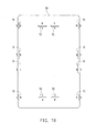
- an accessory 100 interacts with an electronic device 50 shown in FIG. 1B .
- the electronic device 50 may be a portable electronic device, tablet device, personal digital assistant, mobile phone, smart phone, or portable device with large screen.
- the accessory 100 which mechanically or physically separated from the electronic device 50, may be a cover 110, a case, or a back cover with edges or sides contour the edge of the electronic device 50.
- the cover 110 of the accessory 100 may be disposed on the electronic device 50.
- the electronic device 50 may comprise a display and a housing respectively at a front side and a rear side of the electronic device 50.
- the cover 110 may be placed on a front side of the electronic device 50 to cover the display of the electronic device 50.
- the cover 110 may be disposed on the rear side of the electronic device 50 to cover the housing.
- the cover 110 has a plurality of first cover elements 111 disposed in or on the cover 110.
- the first cover element 111 may interact with magnetic field or produce magnetic field, such as permanent magnet, electromagnet, ferromagnetic materials, magnetic element or combination of magnet with different polarities.
- the electronic device 50 has a plurality of first device elements 51 disposed in or on the electronic device 50.
- the first device element 51 may interact with magnetic field or produce magnetic field, such as permanent magnet, electromagnet, ferromagnetic materials, magnetic element or combination of magnet with different polarities.
- the placement of the first cover elements 111 in the cover 110 forms a symmetrical pattern.
- the first device elements 51 in the electronic device 50 also forms a symmetrical pattern.
- the first device elements 51 and the first cover elements 111 are placed so that when a user flips the cover 110 from one of the edges of the electronic device 50, the first cover elements 111 at the edge of the cover 110 are attached to the corresponding edge of the electronic device 50.
- the attraction between the first cover elements 111 and the corresponding first device elements 51 is kept continuously.
- the electronic device 50 is substantially rectangular-plate-shaped, and the first device elements 51 are disposed adjacent to two edges of the electronic device 50.
- the cover 110 is substantially rectangular-plate-shaped similar to the electronic device 50, and the first cover elements 111 are disposed in the cover 110 and adjacent to two edges of the cover 110. Referring FIGS. 2A to 2C , when the cover 110 is flipped from the front side of the electronic device 50 to the rear side of the electronic device 50 along one of the edges of the electronic device 50 and the corresponding edge of the cover 110, the attraction between the first cover elements 111 and the corresponding first device elements 51 is kept continuously. Then, referring FIGS.
- FIGS. 2A to 2C when the cover 110 is flipped from the rear side of the electronic device 50 to the front side of the electronic device 50 along another edge of the electronic device 50 and another edge of the cover 110, the attraction between the first cover elements 111 and the corresponding first device elements 51 is also kept continuously.
- the order of flipping movement from FIGS. 2A to 2E may be reversed from FIGS. 2E to 2A .
- the electronic device 50 has a plurality of second device elements 52 substantially located at the rear side of the electronic device 50 and away from the edges of the electronic device 50.
- the cover 110 has a plurality of second cover elements 112 substantially located in the middle portions 113a away from the edges of the cover 110.
- the second cover elements 112 are aligned to the second device elements 52 respectively so as to attract the second device elements 52 respectively.
- the second device elements 52 and the second cover elements 112 provides additional attraction away from the edges of the electronic device 50 and the cover 110 so that the entire of the cover 110 may be closely attached to the electronic device 50 as shown in FIG. 2A, FIG. 2C or FIG. 2E .
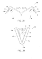
- the cover 110 has two middle portions 113a and four comer portions 113b.
- the middle portions 113a may be substantially trapezoid-plate-shaped, and the corner portions 113b are substantially triangle-plate-shaped.
- the middle portions 113a may be bended, twisted, turned or arched to point to a different direction relative to each other via a central flexible portion 114a of the cover 110.
- the middle portions 113a may be turned via a second trapezoid portion to form a 0 to 360-degree angle related to each other.
- Each of the corner portions 113b may be bended, twisted, turned or arched to point to a different direction relative to the corresponding middle portion 113a via an inclined flexible portion 114b of the cover 110.
- the corner portion 113b may be turned via the corresponding inclined flexible portion 114b to form a 0 to 360-degree angle related to the corresponding middle portions 113a.
- the cover 110 has a plurality of shaping elements 115 embedded in the corner portions 113b respectively, and when the middle portions 113a are bended relative to each other and a neighbor two of the corner portions 113b are overlapped each other, the shaping elements 115, located in the neighbor two of the corner portions 113b respectively, attract each other so that the cover 110 may be kept in a shape of triangular prism to form a stand.
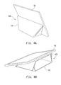
- the cover 110 may be attached to the electronic device 50 by attraction and also tilt the electronic device 50 in different states respectively on a table or the like as shown in FIGS. 4A and 4B .
- All of the elements list above may be a permanent magnet, electric magnet, or any element that may interact with magnetic field or electric field, such as metal, or polar material.
- the element may be combination of a plurality of magnets.
- a shielding may be disposed on the element or between the magnets in the element for shielding the magnetic field in a defined direction or reduce the magnetic flux to an acceptable level so the component in the electronic device 50 may not be affected.
- a conductor or magnetic guide maybe placed on the element or between the magnets in the element to guide the magnetic field to a defined direction or forming a defined magnetic field.
- the accessory 100 in FIG. 5 has a different way to kept the shape thereof so as to stand the electronic device 50 in FIG. 1A .
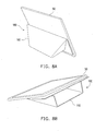
- the cover 110 of the accessory 100 in FIG. 5 has a plurality of first shaping elements 115a embedded in the middle portions 113a respectively and a plurality of second shaping elements 115b embedded in the corner portions 113b respectively, and when the middle portions 113a are bended relative to each other and two of the corner portions 113b are overlapped each other and contact the middle portion 113a respectively, the first shaping elements 115a attract the second shaping elements 115b respectively so that the cover 110 in FIG. 5 may form a stand. Therefore, the cover 110 in FIG. 5 may be attached to the electronic device 50 by attraction and also tilt the electronic device 50 in different states respectively on a table or the like as shown in FIGS. 6A and 6B .
- the cover 110 of the accessory 100 in FIG. 7 has a half portion 113c to replace a side thereof, and has two pairs of second shaping elements 115b in the half portion 113c.
- the half portion 113c is substantially rectangular-plate-shaped and is able to be bended relative to the middle portion 113a via a central flexible portion 114a.
- the second cover elements 112 substantially located in the half portion 113c and the middle portion 113a away from the edges of the cover 110 in FIG. 7 to attract the second device elements 52 of the electronic device 50 in FIG. 1B respectively.
- Each of the pairs of second shaping elements 115b are placed in parallel with south pole of both the second shaping elements 115b facing each other.
- the first shaping elements 115a in the corner portions 112a may be attached to the space between the corresponding pair of the second shaping elements 115b.
- the north pole of the first shaping elements 115a is attracted by the two south poles of the corresponding pair of the second shaping elements 115b so that the cover 110 in FIG. 7 may form a stand. Therefore, the cover 110 in FIG. 7 may be attached to the electronic device 50 by attraction and also tilt the electronic device 50 in different states respectively on a table or the like as shown in FIGS. 8A and 8B .
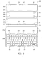
- the accessory 200 is also suitable for the electronic device 50 in FIG. 1B and may further comprise a cover 210 and a keyboard 220, and the keyboard 220 flexibly connected to one of the edges of the cover 210 via a flexible portion 230.
- the cover 210 has a plurality of segments 213 arranged side by side in sequence, and any adjacent two of the segments 211 are able to be bended relative to each other via a flexible portion 214 which is substantially parallel to the edges of the cover 210. Similar to the cover 110 in FIG. 1A , the cover 210 in FIG. 9 also has first cover elements 211.
- the first device elements 51 and the first cover elements 211 are placed so that when a user flips the cover 210 from one of the edges of the electronic device 50, the first cover elements 211 at the edge of the cover 210 are attached to the corresponding edge of the electronic device 50.
- the attraction between the first cover elements 211 and the corresponding first device elements 51 is kept continuously.
- the cover 210 has a plurality of second cover elements 212 substantially located in one or ones of the segments 213 away from the edges of the cover 210.
- the second cover elements 212 are aligned to the second device elements 52 respectively so as to attract the second device elements 52 respectively.
- the second device elements 52 and the second cover elements 212 provides additional attraction away from the edges of the electronic device 50 and the cover 210 so that the entire of the cover 210 may be closely attached to the electronic device 50.
- the keyboard 220 is substantially rectangular-plate-shaped similar to the cover 210, one edge of the keyboard 220 is flexibly connected to the corresponding edge of the cover 210, and the keyboard 220 has a plurality of first keyboard elements 221 embedded in the keyboard 220 adjacent to the other edge of the keyboard 220 away from the cover 210.
- the keyboard 220 has a plurality of second keyboard elements 222 embedded in the keyboard 220 and between the edges of the keyboard 220.
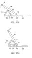
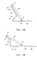
- the keyboard 220 has a margin region 220a and a keyboard region 220b adjacent to the margin region 220a, the second keyboard elements 222 are between the margin region 220a and the keyboard region 220b. Therefore, as shown in FIGS. 10A to 10F , the electronic device 50 has different folding position of the cover 210.
- the segments 213 may be folded along the flexible portion 230.
- the element that is placed inside of the electronic device 50 or the cover 110 or 210 mentioned above may have combine different magnet to achieve best magnetic strength between electronic device 50 and the cover 110 or 210.
- the second device elements 52 and the second cover elements 112 or 212 are combination of magnets. By placing two magnets together with opposite side of pole together, the magnetic field strength of the combined magnet at center of combination is stronger than just a single magnet. By placing two magnets together with same side of magnetic pole together, the magnetic field strength of the combined magnet at center of combination is stronger than just a single magnet.
- FIGS. 12A and 12B for a control method that may be suitable for controlling the electronic device 50 in FIG. 1B coupled with an accessory in FIG. 1A .
- an element 116 such as a magnet
- a sensor 56 such as a hall sensor
- the corner portion 113b of the accessory 100 is moved away from the electronic device 50 can be determined.
- a function of the electronic device 50 is triggered.
- the electronic device 50 has a camera 57 at a corner of a rear side of the electronic device 50
- the corner portion 113b of the cover 110 of the accessory 100 is originally attached on the rear side of the electronic device 50 and the corner portion 113b covers the camera 57 shown in FIG. 12A and is able to be folded to expose the camera 57
- the element 130 in the corner portion 113b is detected by the sensor 56 of the electronic device 50. Therefore, when the corner potion 113b is folded by a user to expose the camera 57, the sensor 56 of the electronic device 50 may detect the element 116 is moved away from the sensor 56, and thus the camera function of the electronic device 50 is activated or triggered. On the contrary, when the corner potion 113b covers the camera 57 again, the sensor 56 of the electronic device 50 may detect the element 116 is moved close to the sensor 56, and thus the camera function of the electronic device 50 is inactivated.
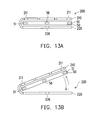
- the electronic device 50 in FIG. 1B and the accessory 200 in FIG. 9 are applied here.
- the element 226 (such as a magnet) is located in the keyboard 220 of the accessory 200
- the sensor 56 (such as a hall sensor) is located in the electronic device 50.
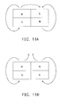
- the electronic device 50 In an initial state shown in FIG. 13A , the electronic device 50 is originally sandwiched between the cover 210 and the keyboard 220.
- the sensor 56 of the electronic device 50 may detect the element 226 is moved away from the sensor 56, and thus a function of the electronic device 50 is activated or triggered, such as the display of the electronic device 50 is turned on.
- the sensor 56 of the electronic device 50 may detect the element 226 is moved close to the sensor 56, and thus the function of the electronic device 50 is inactivated, such as the display of the electronic device 50 is turned off.
Landscapes
- Engineering & Computer Science (AREA)
- Theoretical Computer Science (AREA)
- General Engineering & Computer Science (AREA)
- Computer Hardware Design (AREA)
- Human Computer Interaction (AREA)
- Physics & Mathematics (AREA)
- General Physics & Mathematics (AREA)
- Signal Processing (AREA)
- Computer Networks & Wireless Communication (AREA)
- Casings For Electric Apparatus (AREA)
- Connector Housings Or Holding Contact Members (AREA)
Applications Claiming Priority (2)
| Application Number | Priority Date | Filing Date | Title |
|---|---|---|---|
| US201461986121P | 2014-04-30 | 2014-04-30 | |
| US14/690,485 US10095320B2 (en) | 2014-04-30 | 2015-04-20 | Accessory and control method |
Publications (3)
| Publication Number | Publication Date |
|---|---|
| EP2940880A2 true EP2940880A2 (fr) | 2015-11-04 |
| EP2940880A3 EP2940880A3 (fr) | 2016-03-02 |
| EP2940880B1 EP2940880B1 (fr) | 2019-06-26 |
Family
ID=53040385
Family Applications (1)
| Application Number | Title | Priority Date | Filing Date |
|---|---|---|---|
| EP15165777.2A Active EP2940880B1 (fr) | 2014-04-30 | 2015-04-29 | Accessoire et procédé de commande |
Country Status (4)
| Country | Link |
|---|---|
| US (1) | US10095320B2 (fr) |
| EP (1) | EP2940880B1 (fr) |
| CN (1) | CN105050348B (fr) |
| TW (1) | TWI624206B (fr) |
Families Citing this family (11)
| Publication number | Priority date | Publication date | Assignee | Title |
|---|---|---|---|---|
| US9522560B2 (en) * | 2013-10-08 | 2016-12-20 | Clipbook, Llc | Clipboard |
| US10013060B2 (en) * | 2015-09-18 | 2018-07-03 | Immersion Corporation | Systems and methods for providing haptic effects in response to deformation of a cover for an electronic device |
| TWI629585B (zh) * | 2016-12-09 | 2018-07-11 | 和碩聯合科技股份有限公司 | 可攜式電子裝置的保護套 |
| US11170924B2 (en) * | 2017-03-02 | 2021-11-09 | Microsoft Technology Licensing, Llc | Computing devices, removable support devices, and methods of use |
| USD875735S1 (en) * | 2018-10-19 | 2020-02-18 | Rakuten Kobo Inc. | Case for electronic device |
| US10716376B2 (en) * | 2018-10-19 | 2020-07-21 | Rakuten Kobo, Inc. | Folding protective cover for an electronic device |
| US11749106B2 (en) * | 2018-11-19 | 2023-09-05 | Mark Lamoncha | Stop sign with traffic control features |
| US10996718B2 (en) * | 2019-04-03 | 2021-05-04 | Dell Products, L.P. | Foldable case for a multi-form factor information handling system (IHS) with a detachable keyboard |
| KR102896370B1 (ko) | 2021-01-14 | 2025-12-05 | 삼성전자 주식회사 | 가로 및 세로 방향 거치 가능한 전자 장치 및 전자 장치용 커버 |
| WO2022228404A1 (fr) * | 2021-04-26 | 2022-11-03 | 深圳市乐沐营销顾问有限公司 | Support portatif |
| US20230009746A1 (en) * | 2021-07-09 | 2023-01-12 | Jintai LIU | Tablet computer protective case with multiple folding ways |
Family Cites Families (13)
| Publication number | Priority date | Publication date | Assignee | Title |
|---|---|---|---|---|
| US20140033482A1 (en) * | 2012-08-06 | 2014-02-06 | Correlated Magnetics Research, Llc | Magnetic attachment system having a multi-pole magnetic structure and pole pieces |
| US20100238620A1 (en) | 2009-03-23 | 2010-09-23 | Ram David Adva Fish | Magnetic Notebooks and Tablets |
| US8390412B2 (en) * | 2010-09-17 | 2013-03-05 | Apple Inc. | Protective cover |
| TWI491335B (zh) * | 2011-01-18 | 2015-07-01 | Chiun Mai Comm Systems Inc | 多功能保護套 |
| US20120268911A1 (en) | 2011-04-25 | 2012-10-25 | Ko Ja (Cayman) Co., Ltd. | Protective sleeve for touch control electronic device |
| US8907752B2 (en) | 2011-09-12 | 2014-12-09 | Justin Richard Wodrich | Integrated inductive charging in protective cover |
| US9729685B2 (en) | 2011-09-28 | 2017-08-08 | Apple Inc. | Cover for a tablet device |
| US8820695B2 (en) * | 2012-06-05 | 2014-09-02 | Lenovo (Singapore) Pte. Ltd. | Soft cover for tablet PC |
| US9496102B2 (en) * | 2012-09-11 | 2016-11-15 | Logitech Europe S.A. | Protective cover for a tablet computer |
| CN103729026B (zh) * | 2012-10-16 | 2017-09-01 | 华硕电脑股份有限公司 | 保护盖 |
| US9049911B1 (en) * | 2013-09-23 | 2015-06-09 | Amazon Technologies, Inc. | Electronic device cover |
| US9241558B2 (en) * | 2013-10-23 | 2016-01-26 | Wal-Mart Stores, Inc. | Electronic device camera case and method of providing the same |
| CN103618821B (zh) | 2013-10-30 | 2015-09-23 | 广东欧珀移动通信有限公司 | 电子设备屏幕状态的控制方法及装置 |
-
2015
- 2015-04-20 US US14/690,485 patent/US10095320B2/en active Active
- 2015-04-29 TW TW104113708A patent/TWI624206B/zh active
- 2015-04-29 EP EP15165777.2A patent/EP2940880B1/fr active Active
- 2015-04-29 CN CN201510212077.XA patent/CN105050348B/zh active Active
Non-Patent Citations (1)
| Title |
|---|
| None |
Also Published As
| Publication number | Publication date |
|---|---|
| EP2940880A3 (fr) | 2016-03-02 |
| EP2940880B1 (fr) | 2019-06-26 |
| US20150316999A1 (en) | 2015-11-05 |
| CN105050348A (zh) | 2015-11-11 |
| TW201547355A (zh) | 2015-12-16 |
| TWI624206B (zh) | 2018-05-11 |
| CN105050348B (zh) | 2018-03-13 |
| US10095320B2 (en) | 2018-10-09 |
Similar Documents
| Publication | Publication Date | Title |
|---|---|---|
| EP2940880A2 (fr) | Accessoire et procédé de commande | |
| KR102550089B1 (ko) | 전자 디바이스에서의 자기 레이아웃 및 전자 디바이스를 위한 액세서리 디바이스 | |
| US10855819B2 (en) | Mobile terminal | |
| US20210099026A1 (en) | Magnetic alignment systems for electronic devices | |
| KR102491848B1 (ko) | 가요성 힌지 구조물을 갖는 모바일 컴퓨팅 디바이스 | |
| US10380383B2 (en) | Screen protection filter | |
| US8975991B2 (en) | Cover | |
| US8143982B1 (en) | Foldable accessory device | |
| KR101522003B1 (ko) | 휴대기기용 보호케이스 | |
| US20120069502A1 (en) | Magnetic attachment | |
| JP6643742B2 (ja) | 情報処理装置 | |
| US20140102924A1 (en) | Protecting cover | |
| KR20180029259A (ko) | 자기적으로 정렬된 액세서리 대 디바이스 연결 | |
| US11526227B2 (en) | Foldable terminal apparatus, terminal control method, terminal apparatus, and non-transitory computer-readable storage medium | |
| US20150305459A1 (en) | Protection device for an electronic device | |
| KR101597336B1 (ko) | 커버 디바이스 | |
| CN205581709U (zh) | 保护套及终端 | |
| KR101636668B1 (ko) | 핸드폰 보호케이스 | |
| DK201870050A1 (da) | Privacy Screenprotector | |
| JP3194429U (ja) | モバイル機器変形保護カバー | |
| JP6570958B2 (ja) | 携帯型の情報処理装置 | |
| EP2816443A2 (fr) | Appareil de protection pour dispositif électronique | |
| JP2013030054A (ja) | 装置収容ケース | |
| JP3205528U (ja) | 電話機能付き携帯端末用ケース | |
| KR20140048366A (ko) | 휴대용 전자기기 보호케이스 |
Legal Events
| Date | Code | Title | Description |
|---|---|---|---|
| PUAI | Public reference made under article 153(3) epc to a published international application that has entered the european phase |
Free format text: ORIGINAL CODE: 0009012 |
|
| 17P | Request for examination filed |
Effective date: 20150429 |
|
| AK | Designated contracting states |
Kind code of ref document: A2 Designated state(s): AL AT BE BG CH CY CZ DE DK EE ES FI FR GB GR HR HU IE IS IT LI LT LU LV MC MK MT NL NO PL PT RO RS SE SI SK SM TR |
|
| AX | Request for extension of the european patent |
Extension state: BA ME |
|
| PUAL | Search report despatched |
Free format text: ORIGINAL CODE: 0009013 |
|
| RIC1 | Information provided on ipc code assigned before grant |
Ipc: H04M 1/18 20060101ALI20160120BHEP Ipc: H04B 1/3888 20150101AFI20160120BHEP |
|
| AK | Designated contracting states |
Kind code of ref document: A3 Designated state(s): AL AT BE BG CH CY CZ DE DK EE ES FI FR GB GR HR HU IE IS IT LI LT LU LV MC MK MT NL NO PL PT RO RS SE SI SK SM TR |
|
| AX | Request for extension of the european patent |
Extension state: BA ME |
|
| 17Q | First examination report despatched |
Effective date: 20160216 |
|
| RBV | Designated contracting states (corrected) |
Designated state(s): AL AT BE BG CH CY CZ DE DK EE ES FI FR GB GR HR HU IE IS IT LI LT LU LV MC MK MT NL NO PL PT RO RS SE SI SK SM TR |
|
| STAA | Information on the status of an ep patent application or granted ep patent |
Free format text: STATUS: EXAMINATION IS IN PROGRESS |
|
| GRAP | Despatch of communication of intention to grant a patent |
Free format text: ORIGINAL CODE: EPIDOSNIGR1 |
|
| STAA | Information on the status of an ep patent application or granted ep patent |
Free format text: STATUS: GRANT OF PATENT IS INTENDED |
|
| INTG | Intention to grant announced |
Effective date: 20190115 |
|
| GRAS | Grant fee paid |
Free format text: ORIGINAL CODE: EPIDOSNIGR3 |
|
| GRAA | (expected) grant |
Free format text: ORIGINAL CODE: 0009210 |
|
| STAA | Information on the status of an ep patent application or granted ep patent |
Free format text: STATUS: THE PATENT HAS BEEN GRANTED |
|
| AK | Designated contracting states |
Kind code of ref document: B1 Designated state(s): AL AT BE BG CH CY CZ DE DK EE ES FI FR GB GR HR HU IE IS IT LI LT LU LV MC MK MT NL NO PL PT RO RS SE SI SK SM TR |
|
| REG | Reference to a national code |
Ref country code: GB Ref legal event code: FG4D |
|
| REG | Reference to a national code |
Ref country code: CH Ref legal event code: EP |
|
| REG | Reference to a national code |
Ref country code: AT Ref legal event code: REF Ref document number: 1149491 Country of ref document: AT Kind code of ref document: T Effective date: 20190715 |
|
| REG | Reference to a national code |
Ref country code: DE Ref legal event code: R096 Ref document number: 602015032572 Country of ref document: DE |
|
| REG | Reference to a national code |
Ref country code: IE Ref legal event code: FG4D |
|
| REG | Reference to a national code |
Ref country code: NL Ref legal event code: FP |
|
| PG25 | Lapsed in a contracting state [announced via postgrant information from national office to epo] |
Ref country code: HR Free format text: LAPSE BECAUSE OF FAILURE TO SUBMIT A TRANSLATION OF THE DESCRIPTION OR TO PAY THE FEE WITHIN THE PRESCRIBED TIME-LIMIT Effective date: 20190626 Ref country code: SE Free format text: LAPSE BECAUSE OF FAILURE TO SUBMIT A TRANSLATION OF THE DESCRIPTION OR TO PAY THE FEE WITHIN THE PRESCRIBED TIME-LIMIT Effective date: 20190626 Ref country code: NO Free format text: LAPSE BECAUSE OF FAILURE TO SUBMIT A TRANSLATION OF THE DESCRIPTION OR TO PAY THE FEE WITHIN THE PRESCRIBED TIME-LIMIT Effective date: 20190926 Ref country code: LT Free format text: LAPSE BECAUSE OF FAILURE TO SUBMIT A TRANSLATION OF THE DESCRIPTION OR TO PAY THE FEE WITHIN THE PRESCRIBED TIME-LIMIT Effective date: 20190626 Ref country code: FI Free format text: LAPSE BECAUSE OF FAILURE TO SUBMIT A TRANSLATION OF THE DESCRIPTION OR TO PAY THE FEE WITHIN THE PRESCRIBED TIME-LIMIT Effective date: 20190626 Ref country code: AL Free format text: LAPSE BECAUSE OF FAILURE TO SUBMIT A TRANSLATION OF THE DESCRIPTION OR TO PAY THE FEE WITHIN THE PRESCRIBED TIME-LIMIT Effective date: 20190626 |
|
| REG | Reference to a national code |
Ref country code: LT Ref legal event code: MG4D |
|
| PG25 | Lapsed in a contracting state [announced via postgrant information from national office to epo] |
Ref country code: BG Free format text: LAPSE BECAUSE OF FAILURE TO SUBMIT A TRANSLATION OF THE DESCRIPTION OR TO PAY THE FEE WITHIN THE PRESCRIBED TIME-LIMIT Effective date: 20190926 Ref country code: GR Free format text: LAPSE BECAUSE OF FAILURE TO SUBMIT A TRANSLATION OF THE DESCRIPTION OR TO PAY THE FEE WITHIN THE PRESCRIBED TIME-LIMIT Effective date: 20190927 Ref country code: LV Free format text: LAPSE BECAUSE OF FAILURE TO SUBMIT A TRANSLATION OF THE DESCRIPTION OR TO PAY THE FEE WITHIN THE PRESCRIBED TIME-LIMIT Effective date: 20190626 Ref country code: RS Free format text: LAPSE BECAUSE OF FAILURE TO SUBMIT A TRANSLATION OF THE DESCRIPTION OR TO PAY THE FEE WITHIN THE PRESCRIBED TIME-LIMIT Effective date: 20190626 |
|
| REG | Reference to a national code |
Ref country code: AT Ref legal event code: MK05 Ref document number: 1149491 Country of ref document: AT Kind code of ref document: T Effective date: 20190626 |
|
| PG25 | Lapsed in a contracting state [announced via postgrant information from national office to epo] |
Ref country code: SK Free format text: LAPSE BECAUSE OF FAILURE TO SUBMIT A TRANSLATION OF THE DESCRIPTION OR TO PAY THE FEE WITHIN THE PRESCRIBED TIME-LIMIT Effective date: 20190626 Ref country code: PT Free format text: LAPSE BECAUSE OF FAILURE TO SUBMIT A TRANSLATION OF THE DESCRIPTION OR TO PAY THE FEE WITHIN THE PRESCRIBED TIME-LIMIT Effective date: 20191028 Ref country code: CZ Free format text: LAPSE BECAUSE OF FAILURE TO SUBMIT A TRANSLATION OF THE DESCRIPTION OR TO PAY THE FEE WITHIN THE PRESCRIBED TIME-LIMIT Effective date: 20190626 Ref country code: RO Free format text: LAPSE BECAUSE OF FAILURE TO SUBMIT A TRANSLATION OF THE DESCRIPTION OR TO PAY THE FEE WITHIN THE PRESCRIBED TIME-LIMIT Effective date: 20190626 Ref country code: AT Free format text: LAPSE BECAUSE OF FAILURE TO SUBMIT A TRANSLATION OF THE DESCRIPTION OR TO PAY THE FEE WITHIN THE PRESCRIBED TIME-LIMIT Effective date: 20190626 Ref country code: EE Free format text: LAPSE BECAUSE OF FAILURE TO SUBMIT A TRANSLATION OF THE DESCRIPTION OR TO PAY THE FEE WITHIN THE PRESCRIBED TIME-LIMIT Effective date: 20190626 |
|
| PG25 | Lapsed in a contracting state [announced via postgrant information from national office to epo] |
Ref country code: SM Free format text: LAPSE BECAUSE OF FAILURE TO SUBMIT A TRANSLATION OF THE DESCRIPTION OR TO PAY THE FEE WITHIN THE PRESCRIBED TIME-LIMIT Effective date: 20190626 Ref country code: IS Free format text: LAPSE BECAUSE OF FAILURE TO SUBMIT A TRANSLATION OF THE DESCRIPTION OR TO PAY THE FEE WITHIN THE PRESCRIBED TIME-LIMIT Effective date: 20191026 Ref country code: ES Free format text: LAPSE BECAUSE OF FAILURE TO SUBMIT A TRANSLATION OF THE DESCRIPTION OR TO PAY THE FEE WITHIN THE PRESCRIBED TIME-LIMIT Effective date: 20190626 Ref country code: IT Free format text: LAPSE BECAUSE OF FAILURE TO SUBMIT A TRANSLATION OF THE DESCRIPTION OR TO PAY THE FEE WITHIN THE PRESCRIBED TIME-LIMIT Effective date: 20190626 |
|
| PG25 | Lapsed in a contracting state [announced via postgrant information from national office to epo] |
Ref country code: TR Free format text: LAPSE BECAUSE OF FAILURE TO SUBMIT A TRANSLATION OF THE DESCRIPTION OR TO PAY THE FEE WITHIN THE PRESCRIBED TIME-LIMIT Effective date: 20190626 |
|
| PG25 | Lapsed in a contracting state [announced via postgrant information from national office to epo] |
Ref country code: DK Free format text: LAPSE BECAUSE OF FAILURE TO SUBMIT A TRANSLATION OF THE DESCRIPTION OR TO PAY THE FEE WITHIN THE PRESCRIBED TIME-LIMIT Effective date: 20190626 Ref country code: PL Free format text: LAPSE BECAUSE OF FAILURE TO SUBMIT A TRANSLATION OF THE DESCRIPTION OR TO PAY THE FEE WITHIN THE PRESCRIBED TIME-LIMIT Effective date: 20190626 |
|
| PG25 | Lapsed in a contracting state [announced via postgrant information from national office to epo] |
Ref country code: IS Free format text: LAPSE BECAUSE OF FAILURE TO SUBMIT A TRANSLATION OF THE DESCRIPTION OR TO PAY THE FEE WITHIN THE PRESCRIBED TIME-LIMIT Effective date: 20200224 |
|
| REG | Reference to a national code |
Ref country code: DE Ref legal event code: R097 Ref document number: 602015032572 Country of ref document: DE |
|
| PLBE | No opposition filed within time limit |
Free format text: ORIGINAL CODE: 0009261 |
|
| STAA | Information on the status of an ep patent application or granted ep patent |
Free format text: STATUS: NO OPPOSITION FILED WITHIN TIME LIMIT |
|
| PG2D | Information on lapse in contracting state deleted |
Ref country code: IS |
|
| 26N | No opposition filed |
Effective date: 20200603 |
|
| PG25 | Lapsed in a contracting state [announced via postgrant information from national office to epo] |
Ref country code: SI Free format text: LAPSE BECAUSE OF FAILURE TO SUBMIT A TRANSLATION OF THE DESCRIPTION OR TO PAY THE FEE WITHIN THE PRESCRIBED TIME-LIMIT Effective date: 20190626 |
|
| PG25 | Lapsed in a contracting state [announced via postgrant information from national office to epo] |
Ref country code: MC Free format text: LAPSE BECAUSE OF FAILURE TO SUBMIT A TRANSLATION OF THE DESCRIPTION OR TO PAY THE FEE WITHIN THE PRESCRIBED TIME-LIMIT Effective date: 20190626 |
|
| REG | Reference to a national code |
Ref country code: CH Ref legal event code: PL |
|
| PG25 | Lapsed in a contracting state [announced via postgrant information from national office to epo] |
Ref country code: LI Free format text: LAPSE BECAUSE OF NON-PAYMENT OF DUE FEES Effective date: 20200430 Ref country code: CH Free format text: LAPSE BECAUSE OF NON-PAYMENT OF DUE FEES Effective date: 20200430 Ref country code: LU Free format text: LAPSE BECAUSE OF NON-PAYMENT OF DUE FEES Effective date: 20200429 |
|
| REG | Reference to a national code |
Ref country code: BE Ref legal event code: MM Effective date: 20200430 |
|
| PG25 | Lapsed in a contracting state [announced via postgrant information from national office to epo] |
Ref country code: BE Free format text: LAPSE BECAUSE OF NON-PAYMENT OF DUE FEES Effective date: 20200430 |
|
| PG25 | Lapsed in a contracting state [announced via postgrant information from national office to epo] |
Ref country code: IE Free format text: LAPSE BECAUSE OF NON-PAYMENT OF DUE FEES Effective date: 20200429 |
|
| PG25 | Lapsed in a contracting state [announced via postgrant information from national office to epo] |
Ref country code: MT Free format text: LAPSE BECAUSE OF FAILURE TO SUBMIT A TRANSLATION OF THE DESCRIPTION OR TO PAY THE FEE WITHIN THE PRESCRIBED TIME-LIMIT Effective date: 20190626 Ref country code: CY Free format text: LAPSE BECAUSE OF FAILURE TO SUBMIT A TRANSLATION OF THE DESCRIPTION OR TO PAY THE FEE WITHIN THE PRESCRIBED TIME-LIMIT Effective date: 20190626 |
|
| PG25 | Lapsed in a contracting state [announced via postgrant information from national office to epo] |
Ref country code: MK Free format text: LAPSE BECAUSE OF FAILURE TO SUBMIT A TRANSLATION OF THE DESCRIPTION OR TO PAY THE FEE WITHIN THE PRESCRIBED TIME-LIMIT Effective date: 20190626 |
|
| P01 | Opt-out of the competence of the unified patent court (upc) registered |
Effective date: 20230602 |
|
| PGFP | Annual fee paid to national office [announced via postgrant information from national office to epo] |
Ref country code: DE Payment date: 20250305 Year of fee payment: 11 |
|
| PGFP | Annual fee paid to national office [announced via postgrant information from national office to epo] |
Ref country code: GB Payment date: 20260312 Year of fee payment: 12 |
|
| PGFP | Annual fee paid to national office [announced via postgrant information from national office to epo] |
Ref country code: NL Payment date: 20260317 Year of fee payment: 12 |
|
| PGFP | Annual fee paid to national office [announced via postgrant information from national office to epo] |
Ref country code: FR Payment date: 20260309 Year of fee payment: 12 |