EP2940903A1 - Informationsübermittlungsverfahren - Google Patents
Informationsübermittlungsverfahren Download PDFInfo
- Publication number
- EP2940903A1 EP2940903A1 EP13869757.8A EP13869757A EP2940903A1 EP 2940903 A1 EP2940903 A1 EP 2940903A1 EP 13869757 A EP13869757 A EP 13869757A EP 2940903 A1 EP2940903 A1 EP 2940903A1
- Authority
- EP
- European Patent Office
- Prior art keywords
- information
- diagram illustrating
- image
- user
- bright line
- Prior art date
- Legal status (The legal status is an assumption and is not a legal conclusion. Google has not performed a legal analysis and makes no representation as to the accuracy of the status listed.)
- Granted
Links
Images


Classifications
-
- H—ELECTRICITY
- H04—ELECTRIC COMMUNICATION TECHNIQUE
- H04B—TRANSMISSION
- H04B10/00—Transmission systems employing electromagnetic waves other than radio-waves, e.g. infrared, visible or ultraviolet light, or employing corpuscular radiation, e.g. quantum communication
- H04B10/11—Arrangements specific to free-space transmission, i.e. transmission through air or vacuum
- H04B10/114—Indoor or close-range type systems
- H04B10/116—Visible light communication
-
- G—PHYSICS
- G08—SIGNALLING
- G08C—TRANSMISSION SYSTEMS FOR MEASURED VALUES, CONTROL OR SIMILAR SIGNALS
- G08C23/00—Non-electrical signal transmission systems, e.g. optical systems
- G08C23/04—Non-electrical signal transmission systems, e.g. optical systems using light waves, e.g. infrared
-
- H—ELECTRICITY
- H04—ELECTRIC COMMUNICATION TECHNIQUE
- H04N—PICTORIAL COMMUNICATION, e.g. TELEVISION
- H04N21/00—Selective content distribution, e.g. interactive television or video on demand [VOD]
- H04N21/40—Client devices specifically adapted for the reception of or interaction with content, e.g. set-top-box [STB]; Operations thereof
- H04N21/41—Structure of client; Structure of client peripherals
- H04N21/4104—Peripherals receiving signals from specially adapted client devices
- H04N21/4131—Peripherals receiving signals from specially adapted client devices home appliance, e.g. lighting, air conditioning system, metering devices
-
- H—ELECTRICITY
- H04—ELECTRIC COMMUNICATION TECHNIQUE
- H04N—PICTORIAL COMMUNICATION, e.g. TELEVISION
- H04N21/00—Selective content distribution, e.g. interactive television or video on demand [VOD]
- H04N21/40—Client devices specifically adapted for the reception of or interaction with content, e.g. set-top-box [STB]; Operations thereof
- H04N21/43—Processing of content or additional data, e.g. demultiplexing additional data from a digital video stream; Elementary client operations, e.g. monitoring of home network or synchronising decoder's clock; Client middleware
- H04N21/436—Interfacing a local distribution network, e.g. communicating with another STB or one or more peripheral devices inside the home
- H04N21/43615—Interfacing a Home Network, e.g. for connecting the client to a plurality of peripherals
-
- H—ELECTRICITY
- H04—ELECTRIC COMMUNICATION TECHNIQUE
- H04N—PICTORIAL COMMUNICATION, e.g. TELEVISION
- H04N21/00—Selective content distribution, e.g. interactive television or video on demand [VOD]
- H04N21/40—Client devices specifically adapted for the reception of or interaction with content, e.g. set-top-box [STB]; Operations thereof
- H04N21/47—End-user applications
- H04N21/488—Data services, e.g. news ticker
- H04N21/4882—Data services, e.g. news ticker for displaying messages, e.g. warnings, reminders
-
- H—ELECTRICITY
- H04—ELECTRIC COMMUNICATION TECHNIQUE
- H04N—PICTORIAL COMMUNICATION, e.g. TELEVISION
- H04N23/00—Cameras or camera modules comprising electronic image sensors; Control thereof
- H04N23/60—Control of cameras or camera modules
- H04N23/61—Control of cameras or camera modules based on recognised objects
- H04N23/611—Control of cameras or camera modules based on recognised objects where the recognised objects include parts of the human body
-
- H—ELECTRICITY
- H04—ELECTRIC COMMUNICATION TECHNIQUE
- H04N—PICTORIAL COMMUNICATION, e.g. TELEVISION
- H04N23/00—Cameras or camera modules comprising electronic image sensors; Control thereof
- H04N23/60—Control of cameras or camera modules
- H04N23/667—Camera operation mode switching, e.g. between still and video, sport and normal or high- and low-resolution modes
-
- H—ELECTRICITY
- H04—ELECTRIC COMMUNICATION TECHNIQUE
- H04N—PICTORIAL COMMUNICATION, e.g. TELEVISION
- H04N23/00—Cameras or camera modules comprising electronic image sensors; Control thereof
- H04N23/70—Circuitry for compensating brightness variation in the scene
- H04N23/73—Circuitry for compensating brightness variation in the scene by influencing the exposure time
-
- H—ELECTRICITY
- H04—ELECTRIC COMMUNICATION TECHNIQUE
- H04Q—SELECTING
- H04Q9/00—Arrangements in telecontrol or telemetry systems for selectively calling a substation from a main station, in which substation desired apparatus is selected for applying a control signal thereto or for obtaining measured values therefrom
Definitions
- the conventional method is limited to a case in which a device to which the method is applied has three color light sources such as an illuminator.
- the present invention solves this problem, and provides an information communication method that enables communication between various devices including a device with low computational performance.
- the number of bright lines included in the bright line image can be increased for instance as illustrated in FIGS. 311B and 320 described later, which contributes to higher signal transmission efficiency.
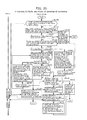
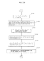
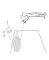
- the following is a description of the flow of processing of communication performed using a camera of a smartphone by transmitting information using a blink pattern of an LED included in a device.
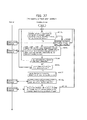
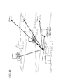
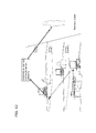
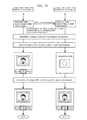
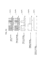
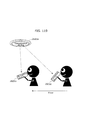
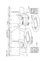
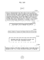
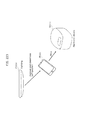
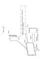
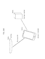
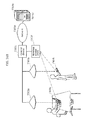
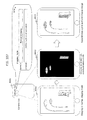
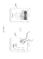
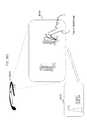
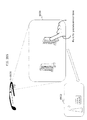
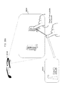
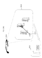
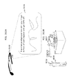
- FIG. 2 is a diagram illustrating an example of communication between the smartphone and the home electric appliances according to the present embodiment.
- FIG. 2 illustrates an example of information communication, and is a diagram illustrating a configuration in which information output by devices such as the television 1101 and the microwave 1106 in FIG. 1 is obtained by a smartphone 1201 owned by a user, thereby obtaining information.
- the devices transmit information using LED blink patterns, and the smartphone 1201 receives the information using an image pickup function of a camera, for instance.
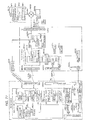
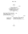
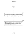
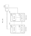
- a transmission speed determination unit 1309 ascertains the performance of a clock generation device inside a device, thereby performing processing of decreasing the transmission speed if the clock generation device is inexpensive and does not operate accurately and increasing the transmission speed if the clock generation device operates accurately.
- a clock generation device exhibits poor performance, it is also possible to reduce an error due to the accumulation of differences of blink intervals because of a long-term communication, by dividing information to be transmitted itself into short pieces.
- a blink information obtaining unit 1406 obtains transmitted information from a blink pattern, and if the information includes information related to a device such as a device ID, an inquiry is made as to information on a related server on a cloud computing system using the information, or interpolation is performed using information stored previously in a device in a wireless-communication area or information stored in the receiver apparatus. This achieves advantageous effect of reducing a time for correcting error due to noise when capturing a light emission pattern or for a user to hold up a smartphone to the light-emitting part of the transmitter device to obtain information already acquired.
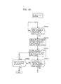
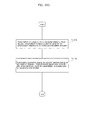
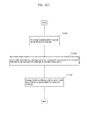
- step 1004a the serviceman presses a setting button of his/her receiving terminal if the performance of the terminal allows detection of blinking at a high speed (for example, 1000 times/second).
- step 1005g if information on a device ID is successfully obtained, also in a reception continuing state, information is transmitted to the server of the cloud computing system, and the information interpolation unit performs interpolation while comparing information acquired from the cloud computing system with information obtained by the blink information obtaining unit.
- bidirectional communication e.g. communication by NFC
- unidirectional communication e.g. communication by LED luminance change
- an information communication device can be achieved which allows communication between various devices including a device which exhibits low computational performance.
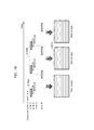
- the light transmission unit may include a second light emitting element disposed in vicinity of a first light emitting element for transmitting information by blinking, and when information transmission is repeatedly performed a certain number of times by the first light emitting element blinking, the second light emitting element may emit light during an interval between an end of the information transmission and a start of the information transmission.
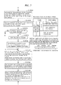
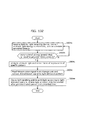
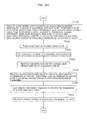
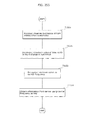
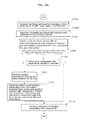
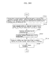
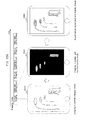
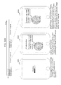
- step 2001d device information (product number and serial number) is collected, and visible light communication is prepared.
- step 2002b visible light communication is started by the perception thereof which is a trigger.
- step 2002c the user obtains device information using the visible light receiving terminal.
- step 2003a position information of a smartphone which has received device information is obtained using the global positioning system (GPS).
- GPS global positioning system
- step 2003e using the device information and the position information, information necessary for initial settings and activation information are collected.
- initial setting information, activity information, and cooperation setting information are transmitted to the smartphone in step 2003i.
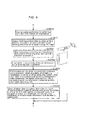
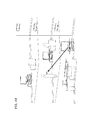
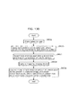
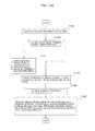
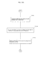
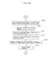
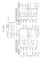
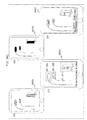
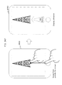
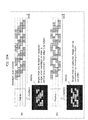
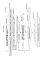
- FIG. 13 is a diagram for describing service exclusively performed by a serviceman when a device fails according to the present embodiment.
- step 2004f the receiving terminal for exclusive use obtains error information and history information in the case of a serviceman.
- step 2004g device information, error information, and history information are transmitted to the cloud computing system, and a repair method is obtained.
- the processing proceeds to step 2004h, the high-speed LED light emission mode is canceled by the serviceman executing a special command, and the processing ends.
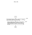
- step 2005f device information, a storage location, and a decryption key are transmitted to the smartphone by visible light communication, which is triggered by the transmission and storage of the dirt information.
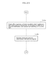
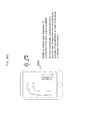
- the visible light communication system which includes the information communication device according to the present embodiment may include: a user information monitoring unit which monitors user information being stored in a terminal; a user information collecting unit which collects user information from devices in the vicinity through NW; and a user registration processing unit which obtains user information and device information to register a user, and may collect user information from accessible devices in the vicinity, which is triggered by no user information being obtained, and register a user together with device information. Accordingly, position information and user information necessary for device setting and user registration are automatically collected and set, which is triggered by device information being obtained by visible light communication, thereby improving convenience by skipping the input and a registration procedure by a user.
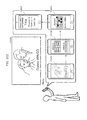
- the intercom indoor unit 3001b displays the order number received from the mobile terminal 3001a on the monitor of the unit itself, thereby showing to the user that the transmission has been completed.
- the intercom outdoor unit 3001c blinks the LED according to the blink patterns designated by the intercom indoor unit 3001b.
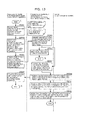
- step 3002a the orderer mobile terminal 3001a reserves delivery using the web browser or an application of the smartphone. Then, the processing proceeds to A in FIG. 17 .
- step 3003e subsequent to A in FIG. 16 , the orderer mobile terminal 3001a selects what to order from the menu presented by the delivery order server.
- step 3003f the orderer mobile terminal 3001a sets the order, and transmits the order to the delivery server.
- the orderer mobile terminal 3001a checks in step 3003g whether the order number has been received.
- the processing returns to step 3003f.
- step 3003h the orderer mobile terminal 3001a displays the received order number, and prompts the user to touch the intercom indoor unit.
- the processing proceeds to B in FIG. 16 .
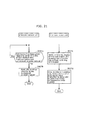
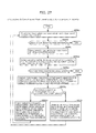
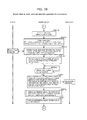
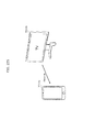
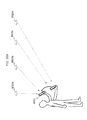
- FIG. 18 illustrates the flow of the deliverer performing optical communication with the intercom outdoor unit 3001c at a delivery destination, using the deliverer mobile terminal 3001f. The following is a description of FIG. 18 .
- step 3005d subsequent to C in FIG. 16 , the intercom indoor unit 3001c gives an instruction to the intercom outdoor unit to blink the LED according to the order number.
- step 3005e the intercom indoor unit 3001b waits until the camera of the intercom outdoor unit recognizes the blinks of the LED of the deliverer mobile terminal.
- step 3005f the intercom indoor unit 3001b checks whether the intercom outdoor unit has notified that the blinks of the LED are recognized. Here, in the case of No, the processing returns to step 3005e. In the case of Yes, the intercom indoor unit 3001b checks the blinks of the LED of the intercom outdoor unit against the order number in step 3005g.
- step 3006a subsequent to F in FIG. 18 the deliverer mobile terminal 3001f starts blinking the LED according to the order number held by the deliverer mobile terminal.
- step 3007a subsequent to K in FIG. 19 the intercom outdoor unit 3001c checks whether a notification has been given regarding whether the blinks of the LED notified from the intercom indoor unit correspond to the order number.
- the processing returns to K in FIG. 19 .
- the processing proceeds to step 3007b, where the intercom outdoor unit blinks the LED to show whether the blinks correspond to the order number, and the processing ends.
- step 3007c subsequent to J in FIG. 19 the intercom indoor unit 3001b notifies the orderer by the display of the intercom indoor unit showing that the deliverer has arrived, with ring tone output.
- step 3007d the intercom indoor unit gives, to the intercom outdoor unit, an instruction to stop blinking the LED and an instruction to blink the LED to show that the blinks correspond to the order number. Then, the processing ends.
- a delivery box for keeping a delivered product is often placed at the entrance, for instance, in the case where an orderer is not at home in an apartment, which is the delivery destination.
- a deliverer puts a delivery product in the delivery box if the orderer is not at home when the deliverer delivers the product.
- optical communication is performed with the camera of the intercom outdoor unit 3001c to transmit the size of the delivery product, whereby the intercom outdoor unit 3001c automatically allows only a delivery box to be used which has a size corresponding to the delivery product.
- step 4001c an inquiry as to information on this user and his/her mobile phone is made to a server.
- step 4001d it is checked in step 4001d whether user information and information on a mobile phone in use are registered in a database (DB) of the server.
- DB database
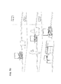
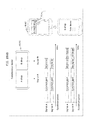
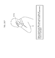
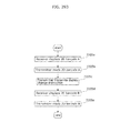
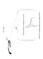
- FIG. 23 is a diagram for describing processing of analyzing user voice characteristics according to the present embodiment. The following is a description of FIG. 23 .
- step 4003a subsequent to B in the diagram operation for displaying a cooking menu list is performed (user operation).
- step 4003f the analysis of environmental sound characteristics is started as parallel processing (processing c).
- step 4003i recognition of user voice is started, and the processing proceeds to C in FIG. 28 .
- step 4005g the characteristics (frequency, sound pressure, and the like) of the obtained sound data are analyzed, and stored as environmental sound characteristics. It should be noted that particularly the sound output by, for instance, a rice cooker near the microwave tends to be incorrectly recognized, and thus characteristics thereof are stored with high importance being set
- step 4005b it is checked in step 4005b whether the collected sound is user voice, and in the case of Yes, the processing returns to step 4005a. In the case of No, the processing proceeds to step 4005c, where characteristics (frequency, sound pressure) of the collected sound are analyzed.
- step 4005d environmental sound characteristics are updated based on the analysis result.
- step 4006d the mobile phone and the sound collecting device in FIG. 25 (sound collecting devices) collect the sound, thereby collecting the tones output from the sound output device.
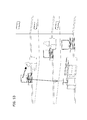
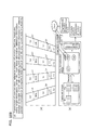
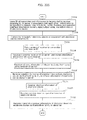
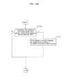
- FIG. 28 is a diagram for describing processing of selecting what to cook and setting detailed operation of a microwave according to the present embodiment. The following is a description of FIG. 28 .
- step 4007d the user is prompted to bring the mobile phone to touch a noncontact integrated circuit (IC) tag embedded in the microwave.
- IC integrated circuit
- step 4007e the processing returns to step 4007e.
- step 4007f the microwave setting command obtained from the server is transmitted to the microwave. Accordingly, all the settings for the microwave necessary for this recipe are made, and the user can cook by only pressing an operation start button of the microwave.
- step 4007h the notification sound of the microwave is adjusted (processing f), and the processing proceeds to D in FIG. 32 .
- step 4008h the notification sound data registered in the mobile phone is registered in the microwave, and the processing ends.
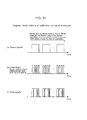
- the recognition rate of the sounds can be further improved by repeating the sounds in the same waveform several times, as with the sound in (a) of FIG. 31 .
- FIG. 33 is a diagram for describing processing of recognizing notification sound of a microwave according to the present embodiment. The following is a description of FIG. 33 .
- step 4012b the details of recognition are checked in step 4012b.
- FIG. 34 is a diagram for describing processing of collecting sound by a sound collecting device in the vicinity and recognizing notification sound of a microwave according to the present embodiment. The following is a description of FIG. 34 .
- step 4013r the processing returns to step 4013a.
- step 4013s the processing proceeds to step 4013s, where it is checked whether an arithmetic unit of the sound collecting device can perform sound recognition.
- information for recognizing notification sound of the microwave is transmitted to the sound collecting device in step 4013u.
- step 4013v the sound collecting device is caused to start collecting and recognizing sound, and transmit the recognition results to the mobile phone.
- step 4013q processing of recognizing notification sound of the microwave is performed until the cooking procedure proceeds to the next cooking step, and the recognition results are transmitted to the mobile phone.
- step 4014u a device (notification device) which is near the detection device, and includes a display unit and a sound output unit is searched for.
- step 4014v the user is notified of the end of operation of the microwave by a screen display or sound of sufficient volume in consideration of the distance from the notification device to the user, and the processing ends.
- step 4015a it is checked in step 4015a whether the mobile phone is being operated, the mobile phone is being carried, an input/output device connected to the mobile phone has received input and output, video and music are being played back, a device located near the mobile phone is being operated, or the user is recognized by a camera or various sensors of a device located near the mobile phone.
- step 4015b the processing proceeds to step 4015b, where it is acknowledged that there is a high probability that the position of the user is close to this mobile phone. Then, the processing returns to step 4015a.
- step 4016a the processing proceeds to step 4016b, where the positions of the mobile phone and the user are registered into the DB, and the processing returns to step 4016a.
- step 4016d it is checked in step 4016d whether a sound collecting device is detected. In the case of No in step 4016d, the processing returns to step 4016a.
- step 4016h if the DB has position information of the user detection device, the information is obtained, thereby determining the position of the user, and the processing returns to step 4016a.
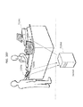
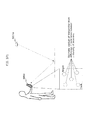
- FIG. 38 is a diagram illustrating that while canceling sound from a sound output device, notification sound of a home electric appliance is recognized, an electronic device which can communicate is caused to recognize a current position of a user (operator), and based on the recognition result of the user position, a device located near the user position is caused to give a notification to the user.
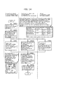
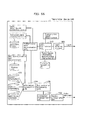
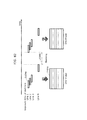
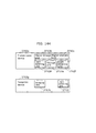
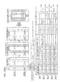
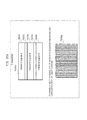
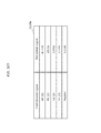
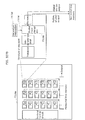
- FIG. 39 is a diagram illustrating content of a database held in a server, a mobile phone, or a microwave according to the present embodiment.
- the model of a microwave As illustrated in FIG. 39 , on a microwave table 4040a, the model of a microwave, data for identifying sound which can be output (speaker characteristics, a modulation method, and the like), for each of various mobile phone models, data of notification sound having characteristics easily recognized by the mobile phone, and data of notification sound easily recognized by a typical mobile phone on the average are held in association with one another.
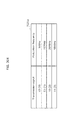
- a user keyword voice table 4040e holds a user and voice waveform data obtained when the user says keywords such as "next” and “return” to be recognized by a mobile phone in association with each other. It should be noted that this data may be obtained by analyzing and changing in the form with which the data is easily handled, rather than the voice waveform data as is.
- a user owned device position table 4040g holds a user, a device that the user owns, and data of sound such as notification sound and operation sound output by the device in association with one another.
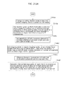
- a user face is recognized using a camera included in a television, and further the movement and presence of the user are recognized using a human sensing sensor of an air-conditioner.
- a television and an air-conditioner may perform this recognition processing, or image data or the like may be transmitted to a mobile phone or a server, and recognition processing may be performed at the transmission destination. From a viewpoint of privacy protection, it is better not to transmit data of the user to an external server.
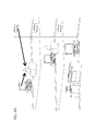
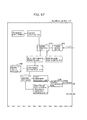
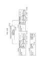
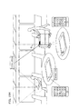
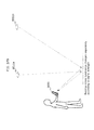
- FIG. 62 is a diagram illustrating that the mobile phone at a remote place notifies the user of information.
- FIG. 62 illustrates that a television having a G unit recognizes notification sound of the microwave which does not have a G unit and transmits information to the mobile phone having a G unit in the house via a G radio wave, the mobile phone in the house transmits the information to the mobile phone at a remote place via the Internet or a carrier communication network, and the mobile phone at the remote place notifies the user of the information.
- the information communication device may include a sound collecting device which searches for an electronic device (sound output device) having sound output functionality from among electronic devices which can communicate with the operation terminal, analyzes sound transmission characteristics between the sound output device and the sound collecting device, obtains output sound data from the sound output device, and cancels, from the collected sound, sound output from the sound output device, based on the sound transmission characteristics and the output sound data.
- a sound collecting device searches for an electronic device (sound output device) having sound output functionality from among electronic devices which can communicate with the operation terminal, analyzes sound transmission characteristics between the sound output device and the sound collecting device, obtains output sound data from the sound output device, and cancels, from the collected sound, sound output from the sound output device, based on the sound transmission characteristics and the output sound data.
- a push button method, a personal identification number (PIN) input method, an NFC method, and the like are specified in the Wi-Fi protected setup (WPS) of wireless LAN, which is set by the Wi-Fi alliance.
- WPS Wi-Fi protected setup
- whether a user using a device is to be authenticated is determined by limiting a time period or determining that the user is in a range where he/she can touch both devices, thereby authenticating the user.
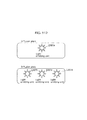
- a transmitter terminal as illustrated in FIG. 66 creates a random number (step 5001a).
- the random number is registered in a registrar of WPS (step 5001b).
- a light emitting element is caused to emit light as indicated by a pattern of the random number registered in the registrar (step 5001c).
- a user shoots a light emitting element of the transmitter terminal, first (step 5001d).
- the receiver terminal receives the random number by shooting (step 5001e).
- the receiver terminal which has received the random number inputs the random number as a PIN of WPS (step 5001f).
- this method is applicable not only to wireless LAN authentication, but also to all the wireless authentication methods which use a common key.
- a transmitter terminal creates a transmitter ID according to the state of the terminal (step 5002a).
- the transmitter ID may be a random number or a key for coding.
- a terminal ID (a MAC address, an IP address) of the transmitter terminal may be included.
- the transmitter terminal emits light as indicated by the pattern of the transmitter ID (step 5002b).
- a receiver device receives the transmitter ID in the same process as in the case of wireless authentication (step 5002f).
- the receiver device creates a receiver ID which can show that the transmitter ID has been received (step 5002g).
- the receiver ID may be a terminal ID of the receiver terminal coded in the transmitter ID.
- the receiver ID may also include a process ID and a password of an application which has been activated in the receiver terminal.
- the receiver terminal broadcasts the receiver ID wirelessly (step 5002h). It should be noted that if a terminal ID of the transmitter terminal is included in the transmitter ID, the receiver terminal may unicast the receiver ID
- the transmitter terminal which has received the receiver ID wirelessly performs authentication with a terminal which has transmitted the received receiver ID, using the transmitter ID shared in both the terminals (step 5002d).
- FIG. 70 is a flowchart illustrating operation of the transmitter terminal according to the present embodiment. The following is a description of FIG. 70 .
- step 5003c it is checked whether there is a wireless response corresponding to the ID indicated by emitted light (step 5003c). If there is a response (Yes in step 5003c), processing of authenticating the terminal which has transmitted the response is performed (step 5003d). It should be noted that if there is no response in step 5003c, the transmitter terminal waits until a timeout time elapses (step 5003i), and ends the processing after displaying there being no response (step 5003j).
- step 5004e authentication processing is started by the transmission terminal (step 5004e), and if the authentication processing has succeeded (Yes in step 5004e), it is determined whether a command is included in the ID obtained by receiving light (step 5004f). If it is determined in step 5004f that a command is included (YES in step 5004f), processing according to the ID is performed (step 5004g).
- the communication using visible light is used for wireless authentication, whereby it can be determined that a user to be authenticated is certainly in a room, and wireless authentication of a home electric appliance can be performed with ease and in a secured manner.
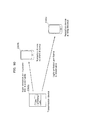
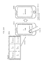
- FIG. 72 is a sequence diagram in which a mobile AV terminal 1 transmits data to a mobile AV terminal 2 according to the present embodiment. Specifically, FIG. 72 is a sequence diagram of data transmission and reception performed using NFC and wireless LAN communication. The following is a description of FIG. 72 .
- the mobile AV terminal 1 displays, on the screen, a confirmation screen for checking whether data transmission is to be performed.
- This confirmation screen may be a screen for requesting a user to select "Yes/No” together with the words "Transmit data?" or may be an interface for starting data transmission by the screen of the mobile AV terminal 1 being touched again.
- the mobile AV terminals 1 and 2 perform data communication by wireless LAN communication, and the mobile AV terminal 1 transmits the transmission target data thereof to the mobile AV terminal 2.
- NFC communication is performed by bringing the mobile AV terminals 1 and 2 to be almost in contact with each other.
- This NFC communication is processing for starting exchange of a still image and video data in the mobile AV terminal 1.
- the mobile AV terminals 1 and 2 transmit data by wireless LAN communication.
- the mobile AV terminal 1 displays, on the screen, video being reproduced normally, whereas the mobile AV terminal 2 which receives data displays, on the screen, data being received.
- the mobile AV terminal 1 displays data being transmitted on the screen, the mobile AV terminal 1 cannot perform other processing, and thus data is transmitted in the background, thereby achieving an advantage of the improvement of a user's convenience.
- the mobile AV terminal 2 which is receiving data displays data being received on the screen so that the received data can be immediately displayed, thereby achieving an advantage of displaying data immediately after reception of the data is completed.
- FIGS. 75 to 77 are system outline diagrams when the mobile AV terminal 1 is a digital camera according to the present embodiment.
- the digital camera (the mobile AV terminal 1) transmits captured image data by a wireless LAN to picture sharing service in an environment where wireless LAN communication can be performed, whereas in an environment where wireless LAN communication cannot be performed, the digital camera transmits data to the mobile AV terminal 2 using a wireless LAN first, and the mobile AV terminal 2 transmits the as-is received data to picture sharing service by mobile phone communication.
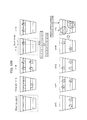
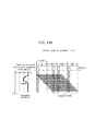
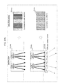
- FIG. 78 illustrates an example of imaging where imaging elements arranged in a line are exposed simultaneously, with the exposure start time being shifted in order of lines.
- exposure line the simultaneously exposed imaging elements
- bright line the line of pixels in the image corresponding to the imaging elements
- a fundamental period of transmission can be recognized by causing the light emitting unit to emit light with a timing slightly different from the timing of exposure of each exposure line.
- the provision of the predetermined non-exposure vacant time is possible by setting a shorter exposure time t E than the time difference t D between the exposure start times of the exposure lines, as in 7502d.
- the exposure time is shortened from the normal imaging mode so as to provide the predetermined non-exposure vacant time.
- the exposure end time of one exposure line and the exposure start time of the next exposure line are the same in the normal imaging mode, too, the exposure time is shortened so as to provide the predetermined non-exposure time.
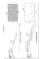
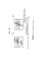
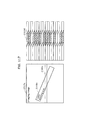
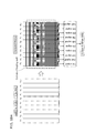
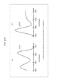
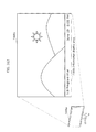
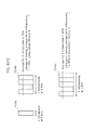
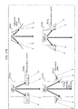
- FIG. 81H is a graph representing the relation between the exposure time t E and the magnitude of high frequency noise when t HT is 20 microseconds. Given that t HT varies depending on the light source, the graph demonstrates that it is efficient to set t E to greater than or equal to 15 microseconds, greater than or equal to 35 microseconds, greater than or equal to 54 microseconds, or greater than or equal to 74 microseconds, each of which is a value equal to the value when the amount of noise is at the maximum.
- t E is desirably larger in terms of high frequency noise reduction, there is also the above-mentioned property that, when t E is smaller, an intermediate-color part is less likely to occur and estimation of light source luminance is easier.
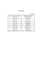
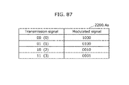
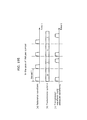
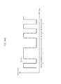
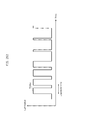
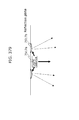
- a modulation method illustrated in FIG. 84 is available as a modulation scheme for causing the light emitting unit to emit light so as to keep the constant moving average of the luminance of the light emitting unit when the temporal resolution of human vision is set as the window width.
- a modulated signal "0" indicates no light emission and a modulated signal "1" indicates light emission, and there is no bias in a transmission signal.
- the average of the luminance of the light emitting unit is about 50% of the luminance at the time of light emission.
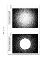
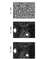
- each capture pixel is proportional to the average luminance of the imaging object in the time during which the imaging element is exposed. Accordingly, if the exposure time is short, a light emission pattern 2217a itself is observed as illustrated in 2217b. If the exposure time is longer, the light emission pattern 2217a is observed as illustrated in 2217c, 2217d, or 2217e.
- Such a light emission pattern enables simultaneous transmission of more information to a reception device that includes an imaging device of a shorter exposure time and less information to a reception device that includes an imaging device of a longer exposure time.
- the light emitting unit is situated at a position not shown on part of exposure lines or there is blanking, it is impossible to capture the whole state of the light emitting unit by the imaging device of the reception device.
- the length of the light emission pattern combining the data unit and the address unit is sufficiently short so that the light emission pattern is captured within one image in the reception device.
- the length of the light emission pattern combining the data unit, the address unit, and the header unit is sufficiently short so that the light emission pattern is captured within one image in the reception device.
- the transmission device determines the information transmission order according to priority.
- the current estimated position of the light emitting unit may be updated based on values of a 9-axis sensor and a gyroscope during the time.
- the light emission probability is 0.75, so that the probability of the light emitting unit in the synthetic image 2212f appearing to emit light when summing n images is 1 - 0.25 n .
- the probability is about 0. 984.
- the orientation of the imaging unit is estimated from sensor values of a gyroscope and a 9-axis sensor and the imaging direction is compensated for before the image synthesis.
- the imaging time is short, and so there is little adverse effect even when the imaging direction is not compensated for.
- light emitting units 2216a, 2216c, and 2216e are emitting light uniformly, while light emitting units 2216b, 2216d, and 2216f are transmitting signals using light emission patterns. Note that the light emitting units 2216b, 2216d, and 2216f may be simply emitting light so as to appear as stripes when captured by the reception device on an exposure line basis.
- the reception device obtains a list of nearby position patterns from a server and analyzes the position pattern based on the list, using the ID or position information of the transmission device transmitted from the transmission device using the light emission pattern, the position of the reception device estimated by a wireless base station, and the position information of the reception device estimated by a GPS, a gyroscope, or a 9-axis sensor as a key.
- the position of the reception device can be estimated from the size, shape, and position information of the light emitting units obtained from the server, the size and shape of the captured position pattern, and the lens characteristics of the imaging unit.
- Examples of a communication device that mainly performs reception include a mobile phone, a digital still camera, a digital video camera, a head-mounted display, a robot (cleaning, nursing care, industrial, etc.), and a surveillance camera as illustrated in FIG. 106 , though the reception device is not limited to such.
- the reception device is a communication device that mainly receives signals, and may also transmit signals according to the method in this embodiment or other methods.
- the light emitting unit is desirably a device that switches between light emission and no light emission at high speed such as an LED lighting or a liquid crystal display using an LED backlight as illustrated in FIG. 108 , though the light emitting unit is not limited to such.
- the luminance change of the light emitting unit can be observed for a longer time.
- the signal can be read even when the light emitting unit is small or the light emitting unit is captured from a long distance.
- the image stabilization may be performed using sensor values of a gyroscope, a 9-axis sensor, and the like, or using an image captured by an imaging device other than the imaging device capturing the light emitting unit.
- the random field of the position information of the reception device estimated at point [Math. 1] x 1 is [Math. 2] P x1
- the random field of the moving direction and the moving distance estimated when moving from point [Math. 3] x 1 to point [Math. 4] x 2 is [Math. 5] M x1x2 .
- the random field of the eventually estimated position information can be calculated at ⁇ k n - 1 P x k ⁇ M x k ⁇ x k + 1 ⁇ P x n .
- the reception device also estimates the position information of the reception device, from the information obtained from the Internet, the imaging direction, and the distance from the reception device to the light emitting device.
- the transmission device desirably transmits the size information of the light emitting unit even in the case where part of the transmission information is missing.
- the reception device estimates the height of the ceiling from the distance between the transmission device 2606b and the reception device 2606c used in the position estimation and, through the use of this estimation result, estimates the distance between the transmission device 2606a and the reception device 2606c.
- transmission methods such as transmission using a light emission pattern, transmission using a sound pattern, and transmission using a radio wave.
- the light emission pattern of the transmission device and the corresponding time may be stored and later transmitted to the transmission device or the centralized control device.
- the transmission device or the centralized control device specifies, based on the light emission pattern and the time, the transmission device captured by the reception device, and stores the position information in the transmission device.
- the reception device obtains the information of the transmission device, the position and size of the transmission device, service information relating to the position, and the like from the server, using the ID of the transmission device included in the signal as a key.
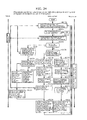
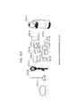
- An imaging unit 2400a includes all or part of: a lens 2400b; an imaging element 2400c; a focus control unit 2400d; an imaging control unit 2400e; a signal detection unit 2400f; and an imaging information storage unit 2400g.
- the imaging unit 2400a starts imaging according to a user operation, an illuminance change, or a sound or voice pattern, when a specific time is reached, when the reception device moves to a specific position, or when instructed by another device via a communication unit.
- a captured image storage unit 2400w stores the image captured by the imaging unit 2400a.
- a received signal storage unit 2400z stores the signal analyzed by the signal analysis unit 2400y.
- a sensor unit 2400q includes all or part of: a GPS 2400r; a magnetic sensor 2400t; an accelerometer 2400s; and a gyroscope 2400u.
- the magnetic sensor 2400t and the accelerometer 2400s may each be a 9-axis sensor.
- a position estimation unit estimates the position or orientation of the reception device, from the information from the sensor unit, the captured image, and the received signal.
- a computation unit 2400aa causes a display unit 2400ab to display the received signal, the estimated position of the reception device, and information (e.g. information relating to a map or locations, information relating to the transmission device) obtained from a network 2400ah based on the received signal or the estimated position of the reception device.
- information e.g. information relating to a map or locations, information relating to the transmission device
- the computation unit 2400aa controls the transmission device based on the information input to the input unit 2400h from the received signal or the estimated position of the reception device.
- a communication unit 2400ag performs communication between terminals without via the network 2400ah, in the case of using a peer-to-peer connection scheme (e.g. Bluetooth).
- a peer-to-peer connection scheme e.g. Bluetooth
- An electronic device 2400aj is controlled by the reception device.
- a server 2400ai stores the information of the transmission device, the position of the transmission device, and information relating to the position of the transmission device, in association with the ID of the transmission device.
- the server 2400ai stores the modulation scheme of the transmission device in association with the position.
- the transmission device includes all of the structure or part of the structure including a light emitting unit, a transmission signal storage unit, a modulation scheme storage unit, and a computation unit.
- a diffusion plate 2401p is a member attached near a light emitting unit 2401q in order to diffuse light of the light emitting unit 2401q.
- the light emitting unit 2401q is composed of a light source, such as an LED or a fluorescent lamp, capable of turning ON and OFF at high speed.
- a light emission control unit 2401r controls ON and OFF of the light emitting unit 2401q.
- a light receiving unit 2401s is composed of a light receiving element or an imaging element.
- the light receiving unit 2401s converts the intensity of received light to an electric signal.
- An imaging unit may be used instead of the light receiving unit 2401s.
- a signal analysis unit 2401t obtains the signal from the pattern of the light received by the light receiving unit 2401s.
- a computation unit 2401u converts a transmission signal stored in a transmission signal storage unit 2401d to a light emission pattern according to a modulation scheme stored in a modulation scheme storage unit 2401e.
- the computation unit 2401u controls communication by editing information in the storage unit 2401a or controlling the light emission control unit 2401r, based on the signal obtained from the signal analysis unit 2401t.
- the computation unit 2401u controls communication by editing information in the storage unit 2401a or controlling the light emission control unit 2401r, based on a signal from an attachment unit 2401w.
- the computation unit 2401u edits information in the storage unit 2401a or controls the light emission control unit 2401r, based on a signal from a communication unit 2401v.
- the computation unit 2401u also edits information in a storage unit 2401b in an attachment device 2401h.
- the computation unit 2401u copies the information in the storage unit 2401b in the attachment device 2401h, to a storage unit 2401a.
- the storage unit 2401a includes all or part of: the transmission signal storage unit 2401d; a shape storage unit 2401f; the modulation scheme storage unit 2401e; and a device state storage unit 2401g.
- the transmission signal storage unit 2401d stores the signal to be transmitted from the light emitting unit 2401q.
- the device state storage unit 2401g stores the state of the transmission device.
- Step 2800h the luminance of the pixel on the approximate line in each exposure line is set as the signal value of the exposure line.
- Step 2800j in the case where the blanking time is less than or equal to a predetermined time, it is determined that the exposure line following the last exposure line of one frame is the first exposure line of the next frame. In the case where the blanking time is greater than the predetermined time, it is determined that unobservable exposure lines as many as the number obtained by dividing the blanking time by the assigned time per exposure line are present between the last exposure line of one frame and the first exposure line of the next frame.
- Step 2800m a pattern indicating a reference position of the signal is detected from the signal of each exposure line.
- Step 2801a a position recognized as the current position of the reception device or a current position probability map is set as self-position prior information.
- Step 2801k the moving direction and distance are calculated from the sensor values of the 9-axis sensor and the gyroscope.
- Step 2801m the moving direction and distance are calculated from the captured image and the orientation of the imaging device. The procedure then returns to Step 2801a.
- Step 2802a the user presses a button.
- Step 2802d the image is captured by the imaging device.
- Step 2803a light is received by the light receiving device or the image is captured by the imaging device.
- Step 2804b whether or not the accumulated energy is greater than or equal to a predetermined amount is determined.
- Step 2804d the transmission signal is read from the storage unit and converted to the light emission pattern.
- Step 2804e the light emitting unit is caused to emit light according to the light emission pattern, and the procedure ends.
- the light emission may be started after a predetermined time period from the recorded time, with the procedure ending thereafter.
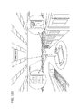
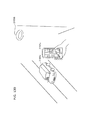
- FIG. 133 is a diagram for describing a situation of receiving information provision inside a station.
- the reception device 2700a obtains information of the lighting or the facility from a server based on the reception information, and further estimates the current position of the reception device 2700a from the size or shape of the captured lighting.
- the reception device 2700a displays information obtained based on a facility ID or position information (2700b).
- the reception device 2700a downloads a map of the facility based on the facility ID, and navigates to a boarding place using ticket information purchased by the user (2700c).
- FIG. 133 illustrates the example inside the train station, the same applies to facilities such as an airport, a harbor, a bus stop, and so on.
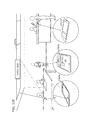
- FIG. 134 is a diagram illustrating a situation of use inside a vehicle.
- a reception device 2704a carried by a passenger and a reception device 2704b carried by a salesperson each receive a signal transmitted from a lighting 2704e, and estimates the current position of the reception device itself.
- each reception device may obtain necessary information for self-position estimation from the lighting 2704e, obtain the information from a server using the information transmitted from the lighting 2704e as a key, or obtain the information beforehand based on position information of a train station, a ticket gate, or the like.
- the reception device 2704a may recognize that the current position is inside the vehicle from ride time information of a ticket purchased by the user (passenger) and the current time, and download information associated with the vehicle.
- Each reception device notifies a server of the current position of the reception device.
- the reception device 2704a notifies the server of a user (passenger) ID, a reception device ID, and ticket information purchased by the user (passenger), as a result of which the server recognizes that the person in the seat is a person entitled to riding or reserved seating.
- FIG. 135 is a diagram illustrating a situation of use inside a store or a shop.
- Reception devices 2707b, 2707c, and 2707d each receive a signal transmitted from a lighting 2707a, estimate the current position of the reception device itself, and notify a server of the current position.
- each reception device may obtain necessary information for self-position estimation and a server address from the lighting 2707a, obtain the necessary information and the server address from another server using information transmitted from the lighting 2707a as a key, or obtain the necessary information and the server address from an accounting system.
- the accounting system associates accounting information with the reception device 2707d, displays the current position of the reception device 2707d (2707c), and delivers the ordered item.
- the seller can deliver the ordered item based on the position information of the reception device 2707b, and the purchaser can purchase the item while remaining seated.
- An electronic device (digital camera) 2701b operates as a wireless connection access point and, as information necessary for the connection, transmits an ID or a password as a light emission pattern.
- the communication between the two electronic devices may be performed via a third electronic device.
- FIG. 137 is a diagram illustrating a range of communication using a light emission pattern or a position pattern.
- the communication range can be easily limited using an obstacle because visible light and its surrounding area wavelengths are used. Moreover, the use of visible light has an advantage that the communication range is recognizable even by the human eye.
- FIG. 138 is a diagram illustrating a situation of indoor use such as an underground city.
- a reception device 2706a receives a signal transmitted from a lighting 2706b, and estimates the current position of the reception device 2706a.
- the reception device 2706a also displays the current position on a map to provide directions, or displays nearby shop information.
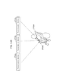
- FIG. 139 is a diagram illustrating a situation of outdoor use such as a street.
- displaying the movements of other vehicles and pedestrians on the map and notifying the user of any approaching vehicles or pedestrians contributes to accident prevention.
- FIG. 140 is a diagram illustrating a situation of route indication.
- a reception device 2703e can download a neighborhood map or estimate the position of the reception device 2703a with an accuracy error of 1 cm to tens of cm, through the use of information transmitted from transmission devices 2703a, 2703b, and 2703c.
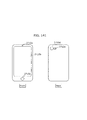
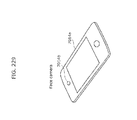
- a reception device in FIG. 141 includes an in camera 2710a, a touch panel 2710b, a button 2710c, an out camera 2710d, and a flash 2710e.
- image stabilization can be performed by estimating the movement or orientation of the reception device from an image captured by the in camera.
- a transmission device 1 receives light of a light emitting unit of a transmission device 2 by a light receiving unit, to obtain a signal transmitted from the transmission device 2 and its transmission timing.
- the transmission device 1 transmits a part common with the transmission signal of the transmission device 2 by emitting light in the same pattern synchronously with the light emission of the transmission device 2.
- the transmission device 1 also transmits a part not common with the transmission signal of the transmission device 2, during a time in which the transmission device 2 transmits no signal.
- the transmission device 1 specifies a period appropriately and transmits the uncommon part according to the period.
- the transmission device 2 receives the light emitted from the transmission device 1 by a light receiving unit, detects that a different signal is transmitted at the same time, and transmits an uncommon part of signal during a time in which the transmission device 1 transmits no signal.
- CSMA/CD Carrier Sense Multiple Access with Collision Detection
- the transmission device 1 causes the light emitting unit to emit light using its own information as a light emission pattern.
- the transmission device 2 obtains the information of the transmission device 1 by the light receiving unit.
- the transmission device generates a transmission device arrangement map by exchanging, between communicable transmission devices, their information.
- the transmission device also calculates an optimal light emission pattern as a whole so as to avoid collisions in signal transmission using light emission. Further, the transmission device obtains information obtained by the other transmission device(s), through communication between the transmission devices.
- a transmission device stores information stored in a storage unit of an attachment device into a storage unit of the transmission device, when the transmission device is attached to the attachment device or the information stored in the storage unit of the attachment device is changed.
- the information stored in the storage unit of the attachment device or the transmission device includes a transmission signal and its transmission timing.
- a shape storage unit in the transmission device stores a position relation between a center position of a light emitting unit and an attachment unit of the transmission device.
- the transmission device When transmitting position information, transmits position information obtained by adding the position relation to position information stored in the storage unit.
- Position Information is stored into the storage unit of the attachment device upon building construction or the like.
- the accurate position is stored through the use of a design or CAD data of the building. Transmitting the position information from the transmission device upon building construction enables position identification, which may be utilized for construction automation, material use position identification, and the like.
- the attachment device notifies the centralized control device of the information of the transmission device.
- the attachment device notifies the centralized control device that a device other than the transmission device is attached.
- a transmission device receives light by a light receiving unit, obtains information from the light pattern by a signal analysis unit, and stores the information into a storage unit. Upon light reception, the transmission device converts information stored in the storage unit to a light emission pattern and causes a light emitting unit to emit light.
- Information about the shape of the transmission device is stored in a shape storage unit.
- Information about the shape of the transmission device is stored in a shape storage unit.
- the reception device may transmit the signal transmitted from the transmission device according to the time of image capture so that the transmission device or the centralized control device specifies the transmission device captured by the reception device using the time.
- the information may be transmitted from the reception device to the transmission device using a sound pattern, where the communication unit of the reception device is a sound emitting unit and the communication unit of the transmission device is a sound receiving unit.
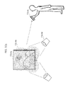
- FIG. 146 is a diagram illustrating a situation of use in combination with 2D (two-dimensional) barcode.
- the user sets a communication device 2714a and a communication device 2714d opposed to each other.
- the communication device 2714a displays transmission information on a display as 2D barcode 2714c.
- the communication device 2714d reads the 2D barcode 2714c by a 2D barcode reading unit 2714f.
- the communication device 2714d expresses transmission information as a light emission pattern of a light emitting unit 2714e.
- the communication device 2714a captures the light emitting unit by an imaging unit 2714b, and reads the signal. According to this method, two-way direct communication is possible. In the case where the amount of data to be transmitted is small, faster communication can be performed than communication via a server.
- a robot 2715a creates a room map 2715f by performing self-position estimation based on signals transmitted from a lighting 2715d and an electronic device 2715c, and stores the map information, the position information, and the IDs of the lighting 2715d and the electronic device 2715c into a server 2715e.
- a reception device 2715b creates the room map 2715f from the signals transmitted from the lighting 2715d and the electronic device 2715c, an image captured during movement, and sensor values of the gyroscope and the 9-axis sensor, and stores the map information, the position information, and the IDs of the lighting 2715d and the electronic device 2715c into the server 2715e.
- the robot 2715a performs cleaning or serving efficiently, based on the map 2715f obtained from the server 2715e.
- the reception device 2715b indicates the cleaning area or the moving destination to the robot 2715a or operates an electronic device in the pointing direction of the reception device, based on the map 2715f obtained from the server 2715e.
- FIG. 148 is a diagram illustrating a situation of electronic device state obtainment and operation.
- the electronic device 2716b reads the control information from the light emission pattern, and operates according to the control information. Upon light reception by the light receiving unit 2716d, the electronic device 2716b converts information indicating the state of the electronic device to a light emission pattern, and causes a light emitting unit 2716c to emit light. Moreover, in the case where there is information to be notified to the user such as when the operation ends or when an error occurs, the electronic device 2716b converts the information to a light emission pattern and causes the light emitting unit 2716c to emit light.
- the communication device 2716a captures the image of the light emitting unit 2716c, and obtains the transmitted signal.
- FIG. 149 is a diagram illustrating a situation of recognizing a captured electronic device.
- a communication device 2717a has communication paths to an electronic device 2717b and an electronic device 2717e, and transmits an ID display instruction to each electronic device.
- the electronic device 2717b receives the ID display instruction, and transmits an ID signal using a light emission pattern of a light emitting unit 2717c.
- the electronic device 2717e receives the ID display instruction, and transmits an ID signal using a position pattern with light emitting units 2717f, 2717g, 2717h, and 2717i.
- the communication device 2717a recognizes the captured electronic device and the position relation between the electronic device and the reception device, from the light emission pattern or the position pattern of the light emitting unit(s) in the captured image.
- the electronic device desirably includes three or more light emitting units to enable the recognition of the position relation between the electronic device and the reception device.
- a stage 2718e for augmented reality display is a light emission pattern or a position pattern of light emitting units 2718a, 2718b, 2718c, and 2718d, to transmit information of the augmented reality object and a reference position for displaying the augmented reality object.
- a reception device superimposes an augmented reality object 2718f on a captured image and displays it, based on the received information.
- the size of a figure displayed according to the moving distance of the imaging range is adjusted as illustrated in FIG. 154 .
- the light emitting unit is not within the center of the imaging range, the light emitting unit is not captured in a sufficiently large size, and also the signal of the light emitting unit can be more easily received by changing the angle between the light emitting unit and the imaging range, such display that prompts the user to point the center of the imaging range to the light emitting unit, prompts the user to get closer to the light emitting unit to capture the image, and also prompts the user to rotate the imaging range is made as illustrated in FIG. 160 .
- the proportion of the signal the reception of which has been completed, the received parts, and the information amount of the received signal are displayed with a progress bar, as illustrated in FIG. 163 .
- the proportion of the signal the reception of which has been completed and the information amount are displayed so as to superimpose on a light emitting unit, as illustrated in FIG. 164 .
- information that the object is a light emitting unit is displayed by, for example, displaying the light emitting unit as blinking, as illustrated in FIG. 165 .
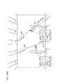
- the traffic light 6003 provides road traffic information to the vehicle 6001.
- the road traffic information mentioned here is information for helping driving, such as congestion information, accident information, and nearby service area information.
- the traffic light 6003 or a lighting 6004 is capable of providing different information depending on signal or light. It is therefore possible to transmit information according to the vehicle position, such as transmitting information only to each vehicle running in a right turn lane.
- this embodiment provides speedups in visible light communication, and so is equally applicable to all other ITS systems using visible light communication.
- the vehicle 6001 transmits information to a vehicle 6001a behind, through a brake lamp or other LED light.
- the vehicle 6001 may also transmit data to an oncoming vehicle 6001b, through a headlight or other front light.
- the communication speed of visible light communication is improved according to the present invention, there is an advantageous effect that information can be transmitted while passing the oncoming vehicle.
- information can be transmitted to many vehicles in a shorter time because the information transmission interval is shorter.
- the increase in communication speed also enables transmission of sound or image information. Hence, richer information can be shared among vehicles.
- radio waves leak to an adjacent room or corridor, so that a function of blocking radio waves by the outer wall to prevent radio waves from leaking out of the room is needed.
- Such blocking radio waves by the outer wall causes a problem that any device communicating with the outside, such as a mobile phone, is unusable.
- the communication can be confined within the reach of light. This has an advantageous effect that, for example, position information of a specific room can be easily transmitted to the user. There is also an advantageous effect that no special device is needed because normally light is blocked by the outer wall.
- the information from the lighting, together with cart information, is transmitted using visible light communication, or transmitted to a server using a wireless LAN or the like.
- a memory is equipped in the cart, and data is collected after the store is closed to compile, in the server, which path each cart has taken.
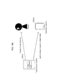
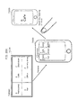
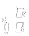
- FIG. 172 illustrates an example of application of using visible light communication according to this embodiment.
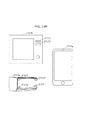
- a mobile phone terminal 6301 transmits data to a camera 6302 using a flash.
- the camera 6302 receives the data transmitted from the mobile phone terminal 6301, from light information received by an imaging unit.
- Camera imaging settings are stored in the mobile phone terminal 6301 beforehand, and setting information is transmitted to the camera 6302.
- the camera can be set using rich user interfaces of the mobile phone terminal.
- the use of the image sensor of the camera enables the setting information to be transmitted from the mobile phone terminal to the camera upon communication between the camera and the mobile phone terminal, with there being no need to provide a new communication device such as a wireless LAN.
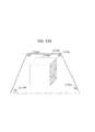
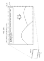
- FIG. 173 is a schematic diagram of the case of adapting the communication method according to this embodiment to underwater communication. Since radio waves do not penetrate water, divers underwater or a ship on the sea and a ship in the sea cannot communicate with each other by radio. Visible light communication according to this embodiment, on the other hand, is available even underwater.
- data can be transmitted from an object or building emitting light.
- a light receiving unit By pointing a light receiving unit to a building, it is possible to obtain guidance information or detailed information of the building. This allows useful information to be provided to tourists.
- the communication method according to this embodiment may be applied to the case of accessing information available only in a specific room in a library.
- the communication method according to this embodiment may be used for exchange of key information, while communication such as a wireless LAN is used for actual communication.
- the communication method according to this embodiment can be used for all imaging devices having MOS sensors and LED communication, and are applicable to digital cameras, smartphones, and so on.
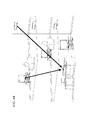
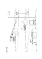
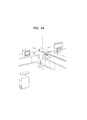
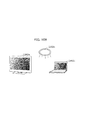
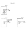
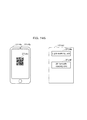
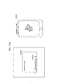
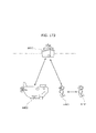
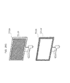
- FIG. 174 is a diagram for describing an example of service provision to a user in Embodiment 9.
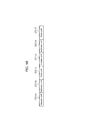
- a network server 4000a, transmitters 4000b, 4000d, and 4000e, receivers 4000c and 4000f, and a building 4000g are illustrated in FIG. 174 .
- the receivers 4000c and 4000f receive signals from the plurality of transmitters 4000b, 4000d, and 4000e in or outside the house and process the received signals, and can thereby provide services to the user.
- the transmitters and the receivers may process the signals individually to provide the services to the user, or provide the services to the user while changing their behaviors or transmitted signals according to instructions from a network in cooperation with the network server 4000a forming the network.
- transmitters and the receivers may be equipped in mobile objects such as vehicles or persons, equipped in stationary objects, or later equipped in existing objects.
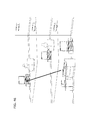
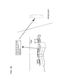
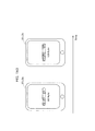
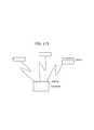
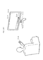
- FIG. 175 is a diagram for describing an example of service provision to a user in Embodiment 9. Transmitters 4001a and a receiver 4001b are illustrated in FIG. 175 .
- the user may perform a registration process or the like for using the information included in the signals on a network server beforehand so that the user can be provided with services by receiving the signals by the receiver 4001b at the place where the transmitters 4001a transmit the signals.
- the user may be provided with services without via the network server.
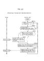
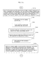
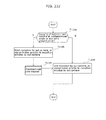
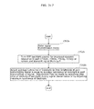
- FIG. 176 is a flowchart illustrating the case where the receiver simultaneously processes the plurality of signals received from the transmitters in this embodiment.
- Step 4002a the procedure starts in Step 4002a.
- Step 4002b the receiver receives the signals from the plurality of light sources.
- Step 4002c the receiver determines the area in which each light source is displayed from the reception result, and extracts the signal from each area.
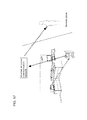
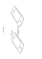
- FIG. 177 is a diagram illustrating an example of the case of realizing inter-device communication by two-way communication in Embodiment 9.
- An example of the case of realizing inter-device communication by two-way communication between a plurality of transmitter-receivers 4003a, 4003b, and 4003c each including a transmitter and a receiver is illustrated in FIG. 175 .
- the transmitter-receivers may be capable of communication between the same devices as in FIG. 175 , or communication between different devices.
- the user can be provided with services in such a manner that applications are distributed to a mobile phone, a smartphone, a personal computer, a game machine, or the like using the communication means in this embodiment or other networks or removable storages and already equipped devices (LED, photodiode, image sensor) are used from the applications.
- the applications may be installed in the device beforehand.
- a service using directivity characteristics in this embodiment is described below, as an example of application of the present invention.
- this is an example of the case of using the present invention in public facilities such as a movie theater, a concert hall, a museum, a hospital, a community center, a school, a company, a shopping arcade, a department store, a government office, and a food shop.
- the present invention achieves lowering of directivity of a signal transmitted from a transmitter to a receiver as compared with conventional visible light communication, so that information can be simultaneously transmitted to many receivers present in a public facility.
- FIG. 178 is a diagram for describing a service using directivity characteristics in Embodiment 9.
- a screen 4004a, a receiver 4004b, and a lighting 4004c are illustrated in FIG. 178 .
- the application of this embodiment to the movie theater can suppress a situation where, during a movie, the user uses such a device (mobile phone, smartphone, personal computer, game machine, etc.) that interferes with the other users enjoying the movie.
- the transmitter uses, as a signal, video projected on the screen 4004a displaying the movie or light emitted from the lighting 4004c disposed in the facility, and includes a command for controlling the receiver 4004b in the signal.
- the command for controlling the receiver 4004b relates to power or reception sound, communication function, LED display, vibration ON/OFF, level adjustment, and the like.
- the strength of directivity can be controlled by the receiver filtering the signal from the transmitter through the use of the intensity of the light source and the like.
- the command or information can be simultaneously transmitted to the receivers present in the facility, by setting low directivity.
- this embodiment is applied to a store where the user's order is received and processed at the place, such as a food shop or a government office
- a signal including the order transmitted from a transmitter held by the user is received by a receiver placed at such a position that can overlook the store, so that which menu is ordered by the user of which seat can be detected.
- the service provider processes the order on a time axis, with it being possible to provide the service of high fairness to the user.
- a secret key or a public key preset between the transmitter and the receiver may be used to encrypt/decrypt the information included in the signal, to thereby restrict transmitters capable of signal transmission and receivers capable of signal reception.
- a protocol such as SSL used in the Internet by default may be employed for a transmission path between the transmitter and the receiver, to prevent signal interception by other devices.
- the following describes a service provided to a user by superimposing of information of the real world captured by a camera and the Internet world, as an example of application of the present invention.
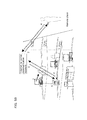
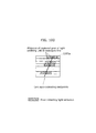
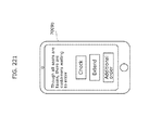
- FIG. 179 is a diagram for describing another example of service provision to a user in Embodiment 9.
- FIG. 179 illustrates an example of a service in the case of applying this embodiment using a camera 4005a equipped in a receiver such as a mobile phone, a smartphone, or a game machine.
- the camera 4005a, light sources 4005b, and superimposition information 4005c are illustrated in FIG. 179 .
- Signals 4005d transmitted from the plurality of light sources 4005b are extracted from the imaging result of the camera 4005a, and information included in the signals 4005d is superimposed on the camera 4005a and displayed.
- Examples of the superimposition information 4005c to be superimposed on the camera 4005a include character strings, images, video, characters, applications, and URLs. Note that the information included in the signals may be processed not only by superimposition on the camera but also by use of sounds, vibrations, or the like.
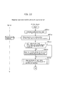
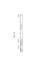
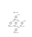
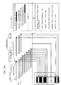
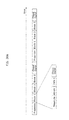
- FIG. 180 is a diagram illustrating a format example of a signal included in a light source emitted from a transmitter.
- Light source characteristics 4006a, a service type 4006b, and service-related information 4006c are illustrated in FIG. 180 .
- the information 4006c related to the service of superimposing the signal received by the receiver on the camera is the result of filtering the information obtainable from the signal according to the information such as the service type 4006b included in the signal transmitted from the transmitter and the distance from the camera to the light source.
- the information to be filtered by the receiver may be determined according to settings made in the receiver beforehand or user preference set in the receiver by the user.
- the receiver can estimate the distance to the transmitter transmitting the signal, and display the distance to the light source.
- the receiver estimates the distance to the transmitter, by performing digital signal processing on the intensity of light emitted from the transmitter captured by the camera.
- the light source characteristics 4006a indicating the intensity, color, type, and the like of the light source are included in the signal transmitted from the transmitter.
- the receiver can estimate the distance with high accuracy. In the case where a plurality of light sources are captured by the receiver, if all light sources have the same intensity, the distance is estimated using the intensity of light of the light source. If there is a transmitter of different intensity out of the light sources captured by the receiver, the distance from the transmitter to the receiver is estimated by not only using the light source amount but also using other distance measurement means in combination.
- the distance may be estimated by using the parallax in image captured by a twin-lens camera, by using an infrared or millimeter wave radar, or by obtaining the moving amount of the receiver by a 9-axis sensor or an image sensor in the receiver and combining the moving distance with triangulation.
- the receiver may not only filter and display the signal using the strength or distance of the signal transmitted from the transmitter, but also adjust the directivity of the signal received from the transmitter.
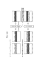
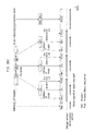
- FIG. 181 is a diagram illustrating a principle in Embodiment 10.
- FIGS. 182 to 194 are each a diagram illustrating an example of operation in Embodiment 10.
- An image sensor illustrated in (a) in FIG. 181 has a delay in exposure time of each line 1.
- the lines have temporally overlapping parts, and so the light signal of the same time is mixed in each line and cannot be identified.
- no overlap occurs as in (a) in FIG. 181 if the exposure time is reduced to less than or equal to a predetermined shutter speed, as a result of which the light signal can be temporally separated and read on a line basis.
- this blanking time problem is solved by changing, when switching from "normal imaging mode” to "light signal reading mode", the access address of the imaging device such as CMOS to read the first read line 1a following the last read line 1h at the bottom. Though this has a slight adverse effect on the image quality, an advantageous effect of capable of continuous (seamless) reading can be achieved, which contributes to significantly improved transmission efficiency.
- one symbol at the maximum can be assigned to one line.
- transmission of 30 kbps at the maximum is theoretically possible when using an imaging element of 30 fps and 1000 lines.
- synchronization can be established by, with reference to the signal of the light receiving element of the camera as in FIG. 182 , vertically changing the line access clock so as to attain the maximum contrast or reduce the data error rate.
- synchronization can be established by receiving one symbol of the light signal in n lines which are 2 or 3 lines as in FIG. 182 .
- HD video For example, dividing an image sensor of 30 fps and 1000 lines into 10 results in 300 kbps. In HD video, there are 1980 pixels in the horizontal direction, so that the division into 50 is possible. This yields 1.5 Mbps, enabling reception of video data. If the number is 200, HD video can be transmitted.
- the device In the case of a lighting device in which flicker needs to be suppressed, light emission is performed by turning OFF or reducing light during one time slot of 4-value PPM, i.e. one time slot of four bits. In this case, though the bitrate decreases by half, flicker is eliminated. Accordingly, the device can be used as a lighting device and transmit light and data.
- FIG. 185 illustrates a situation of light signal reception in a state where all lightings indoors transmit a common signal during a common time slot and an individual lighting L 4 transmits individual sub-information during an individual time slot.
- L 4 has a small area, and so takes time to transmit a large amount of data. Hence, only an ID of several bits is transmitted during the individual time slot, while all of L 1 , L 2 , L 3 , L 4 , and L 5 transmit the same common information during the common time slot.
- time slot B the main area M does not blink but continuously emits light with 1/n of the normal light intensity, as illustrated in the upper right part of FIG. 186A .
- the average light intensity is unchanged when emitting light with 3/4, i.e. 75%, of the normal light intensity, as a result of which flicker can be prevented.
- Blinking in the range where the average light intensity is unchanged causes no flicker, but is not preferable because noise occurs in the reception of the partial areas S 1 , S 2 , S 3 , and S 4 in time slot B.
- S 1 , S 2 , S 3 , and S 4 each transmit a light signal of different data.
- the main area M does not transmit a modulated signal, and so is separated in position as in the screen of the mobile phone in the upper right part of FIG. 186A . Therefore, for example in the case of extracting the image of the area S 1 , stripes appearing in the area can be easily detected because there is little noise, with it being possible to obtain data stably.
- FIG. 186B is a diagram for describing operation of a transmitter and a receiver in this embodiment.
- FIG. 186C is a diagram for describing operation of a transmitter and a receiver in this embodiment.
- the transmitter 8161 transmits the common parts of the signals A and B simultaneously as mentioned above, and then transmits the individual parts of the signals A and B indicating different information simultaneously.
- the receiver 8162 receives the signals from the transmitter 8161, by capturing the transmitter 8161.
- the transmitter 8161 When the transmitter 8161 is transmitting the common parts of the signals A and B, the transmitter 8161 can be captured as one large area without being divided into two areas.
- the receiver 8162 can accordingly receive the common part, even when situated far from the transmitter 8161.
- the receiver 8162 then obtains information associated with the common part from a server, and displays the information. For instance, the server transmits information of all shops shown on the signage which is the transmitter 8161, to the receiver 8162. Alternatively, the server selects information of an arbitrary shop from the shops, and transmits the selected information to the receiver 8162.
- the server transmits, for example, information of a shop that pays the largest registration fee of all shops, to the receiver 8162.
- the receiver 8162 can receive the individual part of the signal A or B.
- the receiver 8162 then obtains information associated with the individual part, from the server.
- a large amount of data including a reference position, a server URL, arrangement information of each ID, and area-specific data broadcasting are transmitted in a common time slot using all lightings as illustrated.
- reception errors can be reduced by assigning signals so that the inverses or logarithms of frequencies are at regular intervals, rather than by assigning frequencies to signals at regular intervals.
- changing the signal per 1/15 second enables transmission of 60 bits per second.
- a typical imaging device captures 30 frames per second. Accordingly, by transmitting the signal at the same frequency for 1/15 second, the transmitter can be reliably captured even if the transmitter is shown only in one part of the captured image.
- the transmission frequency can be analyzed even in the case where light transmitted at a plurality of frequencies in sequence is captured in one frame, and the transmission signal can be received even when the frequency of the transmission signal is changed at time intervals shorter than 1/15 second or 1/30 second.
- the transmission signal sequence can be recognized by performing Fourier transform in a range shorter than one frame.
- captured frames may be concatenated to perform Fourier transform in a range longer than one frame.
- the luminance in the blanking time in imaging is treated as unknown.
- the protection part is a signal of a specific frequency, or is unchanged in luminance (frequency of 0 Hz).
- the FM modulated signal of the frequency f2 is transmitted and then the PPM modulated signal is transmitted.
- the FM modulated signal and the PPM modulated signal are transmitted in this way, even a receiver that supports only one of the methods can receive the information.
- more important information can be transmitted with higher priority, by assigning the more important information to the FM modulated signal which is relatively easy to receive.
- the position of the mobile phone can be calculated with high accuracy in this way.
- the light signal is detected by the face camera to first obtain the position information of the terminal.
- the moving distance l 2 can be calculated from the orientation of the terminal and the change in the pattern of the floor surface using the in camera opposite to the face camera, as in FIG. 191 .
- the pattern of the ceiling may be detected using the face camera.
- FIG. 192 is a diagram illustrating a situation of receiving data broadcasting which is common data from the ceiling lighting and obtaining the position of the user itself from individual data, inside a station.
- FIG. 193 after a mobile terminal on which barcode is displayed displays authentication information and a terminal of a coffee shop reads the authentication information, a light emitting unit in the terminal of the shop emits light and the mobile terminal receives the light according to the present invention to perform mutual authentication.
- the security can be enhanced in this way.
- the authentication may be performed in reverse order.
- the customer carrying the mobile terminal sits at a table and transmits obtained position information to the terminal of the shop via a wireless LAN or the like, as a result of which the position of the customer is displayed on the shop staff's terminal. This enables the shop staff to bring the ordered drink to the table of the position information of the customer ordering the drink.
- the passenger detects his or her position in a train or an airplane according to the method of this embodiment, and orders a product such as food through his/her terminal.
- the crew has a terminal according to the present invention on the cart and, since the ID number of the ordered product is displayed at the position of the customer on the screen, properly delivers the ordered product of the ID to the customer.
- a vertically long display is provided as in the right side of the screen in FIG. 183 .
- the signal can be received by an image sensor of either scan direction.
- a message such as "please rotate to horizontal” may be displayed on the terminal screen to prompt the user to receive the light more accurately and faster.
- the communication speed can be significantly increased by controlling the scan line read clock of the image sensor of the camera to synchronize with the light emission pattern of the light emitting unit as in FIG. 182 .
- an infrared light receiving unit provided in the lighting device of the light emitting unit as a motion sensor may be used for reception, with it being possible to perform bidirectional reception in the lighting device with no additional component.
- the terminal may perform transmission using the electronic flash for the camera, or may be additionally provided with an inexpensive infrared light emitting unit.
- bidirectional communication is realized without significant component addition.
- FIG. 195 is a timing diagram of a transmission signal in an information communication device in Embodiment 11.
- a reference waveform (a) is a clock signal of period T, which serves as the reference for the timing of the transmission signal.
- a transmission symbol (b) represents a symbol string generated based on a data string to be transmitted.
- a transmission waveform (c) is a transmission waveform phase-modulated according to the transmission symbol with respect to the reference waveform. The transmission light source is driven according to this waveform. The phase modulation is performed by phase-shifting the reference waveform in correspondence with the symbol. In this example, symbol 0 is assigned phase 0°, and symbol 1 is assigned phase 180°.
- FIG. 196 is a diagram illustrating the relations between the transmission signal and the reception signal in Embodiment 11.
- the transmission signal is the same as in FIG. 195 .
- the light source emits light only when the transmission signal is 1, with the light emission time being indicated by the diagonally right down shaded area.
- the diagonally right up shaded band represents the time during which the pixels of the image sensor are exposed (exposure time tE).
- the signal charge of the pixels of the image sensor is generated in the area overlapping with the diagonally right down shaded area indicating the light emission time.
- a pixel value p is proportional to the overlapping area.
- the relation of Expression 1 holds between the exposure time tE and the period T.
- tE T / 2 ⁇ 2 ⁇ n + 1 where n is a natural number
- the reception waveform indicates the pixel value p of each line.
- the value of the pixel value axis is normalized with the intensity of received light per period being set as 1.
- the exposure time tE has the section of T(n + 1/2), so that the pixel value p is always in the range of n ⁇ p ⁇ n + 1. In the example in FIG. 196 , 2 ⁇ p ⁇ 3.
- FIGS. 197 to 199 are each a diagram illustrating the relations between the transmission signal and the reception signal for a symbol string different from that in FIG. 196 .
- the transmission signal has a preamble including a consecutive same-symbol string (e.g. string of consecutive symbols 0) (not illustrated).
- the receiver generates the reference (fundamental) signal for reception from the consecutive symbol string in the preamble, and uses it as the timing signal for reading the symbol string from the reception waveform.
- the reception waveform returns a fixed waveform repeating 2 ⁇ 3 ⁇ 2, and the clock signal is generated as the reference signal based on the output timing of the pixel value 3, as illustrated in FIG. 196 .
- the symbol reading from the reception waveform can be performed in such a manner that the reception signal in one section of the reference signal is read where the pixel value 3 is read as symbol 0 and the pixel value 2 is read as symbol 1.
- FIGS. 197 to 199 illustrate the state of reading symbols in the fourth period.
- FIG. 200 is a diagram summarizing FIGS. 196 to 199 . Since the lines are closely aligned, the pixel boundary in the line direction is omitted so that the pixels are continuous in the drawing. The state of reading symbols in the fourth to eighth periods is illustrated here.
- the average of the intensity of the light signal taken for a sufficiently longer time than the period of the reference wave is always constant.
- the frequency of the reference wave appropriately high, it is possible to set the time to be shorter than the time in which humans perceive a change in light intensity.
- the transmission light emitting source observed by the human eye appears to be emitting light uniformly. Since no flicker of the light source is perceived, there is an advantageous effect of causing no annoyance on the user as in the previous embodiment.
- the amplitude modulation (ON/OFF modulation) in the previous embodiment has the problem that the signal frequency (symbol rate) cannot be increased and so the sufficient signal transmission speed cannot be attained.
- the signal leading and trailing edges are detectable even in such a situation, with it being possible to increase the signal frequency and attain the high signal transmission speed.
- phase modulation means the phase modulation for the reference signal waveform.
- a carrier is light, which is amplitude-modulated (ON/OFF modulated) and transmitted. Therefore, the modulation scheme in this signal transmission is one type of amplitude modulation.
- the transmission signal mentioned above is merely an example, and the number of bits per symbol may be set to 2 or more. Besides, the correspondence between the symbol and the phase shift is not limited to 0° and 180°, and an offset may be provided.
- Embodiments 1 to 6 with reference to FIGS. 1 to 77 may be replaced with the structures and operations of the high-speed light emitting means and light signal receiving means described in Embodiment 7 and its subsequent embodiments with reference to FIG. 78 onward, to achieve the same advantageous effects.
- the high-speed light emitting means and receiving means in Embodiment 7 and its subsequent embodiments may equally be replaced with the low-speed light emitting means and receiving means.
- the up/down direction can be detected based on gravity through the use of the 9-axis sensor.
- the light signal may be received by operating the face camera when the front side of the mobile phone is facing upward, and operating the in camera when the front side is facing downward, according to the signal of the 9-axis sensor. This contributes to lower power consumption and faster light signal reception, as unnecessary camera operations can be stopped.
- the same operation may be performed by detecting the orientation of the camera on the table from the brightness of the camera.
- a shutter speed increase command and an imaging element sensitivity increase command may be issued to the imaging circuit unit. This has an advantageous effect of enhancing the sensitivity and making the image brighter. Though noise increases with the increase in sensitivity, such noise is white noise. Since the light signal is in a specific frequency band, the detection sensitivity can be enhanced by separation or removal using a frequency filter. This enables detection of a light signal from a dark lighting device.
- a lighting device in a space which is mainly indoors is caused to emit a light signal
- a camera unit of a mobile terminal including a communication unit, a microphone, a speaker, a display unit, and the camera unit with the in camera and the face camera receives the light signal to obtain position information and the like.
- the position information can be detected by GPS using satellite. Accordingly, by obtaining the position information of the boundary of the light signal area and automatically switching to the signal reception from GPS, an advantageous effect of seamless position detection can be achieved.
- the boundary is detected based on the position information of GPS or the like, to automatically switch to the position information of the light signal.
- the use of a server causes a long response time and is not practical, and therefore only one-way authentication is possible.
- mutual authentication can be carried out by transmitting the light signal from the light emitting unit of the reader of the POS terminal or the like to the face camera unit of the mobile phone. This contributes to enhanced security.
- This embodiment describes each example of application using a receiver such as a smartphone and a transmitter for transmitting information as an LED blink pattern in Embodiments 1 to 11 described above.
- FIG. 201 is a diagram illustrating an example of application of the receiver and the transmitter in Embodiment 12.
- a transmitter 7001a such as a signage of a restaurant transmits identification information (ID) of the transmitter 7001a to a receiver 7001b such as a smartphone.
- ID identification information
- the receiver 7001b obtains information associated with the ID from a server, and displays the information. Examples of the information include a route to the restaurant, availability, and a coupon.
- a transmitter 7042b such as a signage of a movie transmits identification information (ID) of the transmitter 7042b to a receiver 7042a such as a smartphone.
- the receiver 7042a obtains information associated with the ID from a server, and displays the information. Examples of the information include an image 7042c prompting to reserve a seat for the movie, an image 7042d showing scheduled times for the movie, an image 7042e showing availability, and an image 7042f notifying reservation completion.
- FIG. 203 is a diagram illustrating an example of application of the receiver and the transmitter in Embodiment 12.
- a transmitter 7043b such as a signage of a drama transmits identification information (ID) of the transmitter 7043b to a receiver 7043a such as a smartphone. Having received the ID, the receiver 7043a obtains information associated with the ID from a server, and displays the information. Examples of the information include an image 7043c prompting to timer record the drama, an image 7043d prompting to select a recorder for recording the drama, and an image 7043e notifying timer recording completion.
- ID identification information
- the receiver 7043a obtains information associated with the ID from a server, and displays the information. Examples of the information include an image 7043c prompting to timer record the drama, an image 7043d prompting to select a recorder for recording the drama, and an image 7043e notifying timer recording completion.
- FIG. 204 is a diagram illustrating an example of application of the receiver and the transmitter in Embodiment 12.
- a transmitter 7044d or 7044c such as a signage of a store, e.g. a roof sign or a sign placed on a street, transmits identification information (ID) of the transmitter 7044d or 7044c to a receiver 7044a such as a smartphone.
- ID identification information
- the receiver 7044a obtains information associated with the ID from a server, and displays the information. Examples of the information include an image 7044b showing availability, a coupon, and the like of the store.
- FIG. 205 is a flowchart illustrating an example of processing operation of the receiver and the transmitter in Embodiment 12. This flowchart corresponds to the examples of application illustrated in FIGS. 201 to 204 .
- the transmitter transmits the ID (Step 7101b).
- the camera of the receiver is pointed to the transmitter, to receive the ID (Step 7101c).
- the receiver transmits the received ID to the server, and stores the information associated with the ID in the receiver (Step 7101d).
- the receiver also stores a terminal ID and a user ID in the server (Step 7101e).
- the receiver displays the information stored in the server as the information to be displayed on the receiver (Step 7101f).
- the receiver displays the route from the current position to the store or the sales floor (Step 7101h).
- the receiver obtains information from the server according to need, and updates and displays availability information or reservation information (Step 7101i).
- the receiver displays a button for storing the obtained information and a button for cancelling the storage of the displayed information (Step 7101j).
- the reader in the store stores the read information and an ID of the store in the server (Step 7101p).
- the server stores the transmitter, the receiver, and the store in association with each other (Step 7101q). This enables analysis of the advertising effectiveness of the signage.
- FIG. 206 is a diagram illustrating an example of application of the receiver and the transmitter in Embodiment 12.
- FIG. 207 is a flowchart illustrating an example of processing operation of the receiver 7002b and the transmitter 7002a in Embodiment 12.
- the ID of the transmitter 7002a and the information to be provided to the receiver 7002b receiving the ID are stored in the server in association with each other (Step 7102a).
- the information to be provided to the receiver 7002b may include information such as a store name, a product name, map information to a store, availability information, coupon information, stock count of a product, show time of a movie or a play, reservation information, and a URL of a server for reservation or purchase.
- the position relation of information displayed on the transmitter 7002a is stored in the server.
- the transmitter 7002a such as a signage transmits the ID (Step 7102b).
- the camera of the receiver 7002b is pointed to the transmitter 7002a, to receive the ID (Step 7102c).
- the receiver 7002b transmits the received ID to the server, and obtains the information associated with the ID (Step 7102d).
- the receiver 7002b displays the information stored in the server as the information to be displayed on the receiver 7002b (Step 7102e).
- An image which is the information may be displayed on the receiver 7002b while maintaining the position relation of the image displayed on the transmitter 7002a.
- the user selects information displayed on the receiver 7002b, by designation by screen tapping or voice (Step 7102f).
- the receiver 7002b displays the details of the information designated by the user (Step 7102g).
- a transmitter 7003a such as a signage of a plurality of stores transmits identification information (ID) of the transmitter 7003a to a receiver 7003b such as a smartphone. Having received the ID, the receiver 7003b obtains information associated with the ID from a server, and displays information near (e.g. nearest) the center of the captured image of the camera of the receiver 7003b from among the information displayed on the signage.
- ID identification information
- FIG. 209 is a flowchart illustrating an example of processing operation of the receiver 7003b and the transmitter 7003a in Embodiment 12.
- the transmitter 7003a such as a signage transmits the ID (Step 7103b).
- the camera of the receiver 7003b is pointed to the transmitter 7003a, to receive the ID (Step 7103c).
- the receiver 7003b transmits the received ID to the server, and obtains the information associated with the ID (Step 7103d).
- the receiver 7003b displays information nearest the center of the captured image or the designated part from among the information displayed on the signage (Step 7103e).
- FIG. 210 is a diagram illustrating an example of application of the receiver and the transmitter in Embodiment 12.
- a transmitter 7004a such as a signage of a plurality of stores transmits identification information (ID) of the transmitter 7004a to a receiver 7004b such as a smartphone. Having received the ID, the receiver 7004b obtains information associated with the ID from a server, and displays information (e.g. image showing the details of the store "B cafe") near the center of the captured image of the camera of the receiver 7004b from among the information displayed on the signage. When the user flicks left the screen, the receiver 7004b displays an image showing the details of the store "C Bookstore" on the right side of the store “B cafe” on the signage. Thus, the receiver 7004b displays the image in the same position relation as that in the transmitter signage.
- ID identification information
- FIG. 211 is a flowchart illustrating an example of processing operation of the receiver 7004b and the transmitter 7004a in Embodiment 12.
- the ID of the transmitter 7004a and the information to be provided to the receiver 7004b receiving the ID are stored in the server in association with each other (Step 7104a).
- the information to be provided to the receiver 7004b may include information such as a store name, a product name, map information to a store, availability information, coupon information, stock count of a product, show time of a movie or a play, reservation information, and a URL of a server for reservation or purchase.
- the position relation of information displayed on the transmitter 7004a is stored in the server.
- the transmitter 7004a such as a signage transmits the ID (Step 7104b).
- the camera of the receiver 7004b is pointed to the transmitter 7004a, to receive the ID (Step 7104c).
- the receiver 7004b transmits the received ID to the server, and obtains the information associated with the ID (Step 7104d).
- the receiver 7004b displays the information stored in the server as the information to be displayed on the receiver 7004b (Step 7104e).
- the user performs a flick operation on the receiver 7004b (Step 7104f).
- the receiver 7004b changes the display in the same position relation as the information displayed on the transmitter 7004a, according to the user operation (Step 7104g). For example, in the case where the user flicks left the screen to display the information on the right side of the currently displayed information, the information displayed on the transmitter 7004a on the right side of the information currently displayed on the receiver 7004b is displayed on the receiver 7004b.
- the receiver 7005b When the user taps the bottom of the screen (or a down arrow on the screen) of the receiver 7005b, the receiver 7005b displays an image showing the details of the store “E Office” below the store “B cafe” on the signage.
- the receiver 7005b displays an image showing the details of the store "C Bookstore” on the left side of the store “B Cafe” on the signage.
- the receiver 7004b displays the image in the same position relation as that in the transmitter signage.
- FIG. 213 is a flowchart illustrating an example of processing operation of the receiver 7005b and the transmitter 7005a in Embodiment 12.
- the ID of the transmitter 7005a and the information to be provided to the receiver 7005b receiving the ID are stored in the server in association with each other (Step 7105a).
- the information to be provided to the receiver 7005b may include information such as a store name, a product name, map information to a store, availability information, coupon information, stock count of a product, show time of a movie or a play, reservation information, and a URL of a server for reservation or purchase.
- the position relation of information displayed on the transmitter 7005a is stored in the server.
- the transmitter 7005a such as a signage transmits the ID (Step 7105b).
- the camera of the receiver 7005b is pointed to the transmitter 7005a, to receive the ID (Step 7105c).
- the receiver 7005b transmits the received ID to the server, and obtains the information associated with the ID (Step 7105d).
- the receiver 7005b displays the information stored in the server as the information to be displayed on the receiver 7005b (Step 7105e).
- the user taps the edge of the screen displayed on the receiver 7005b or the up, down, left, or right direction indicator displayed on the receiver 7005b (Step 7105f).
- the receiver changes the display in the same position relation as the information displayed on the transmitter 7005a, according to the user operation. For example, in the case where the user taps the right of the screen or the right direction indicator on the screen, the information displayed on the transmitter 7005a on the right side of the information currently displayed on the receiver 7005b is displayed on the receiver 7005b.
- FIG. 215 is a flowchart illustrating an example of processing operation of the receiver and the transmitter 7006a in Embodiment 12.
Landscapes
- Engineering & Computer Science (AREA)
- Signal Processing (AREA)
- Multimedia (AREA)
- Computer Networks & Wireless Communication (AREA)
- Physics & Mathematics (AREA)
- Automation & Control Theory (AREA)
- Electromagnetism (AREA)
- General Physics & Mathematics (AREA)
- Optical Communication System (AREA)
- Telephonic Communication Services (AREA)
- Selective Calling Equipment (AREA)
- Studio Devices (AREA)
- Telephone Function (AREA)
Applications Claiming Priority (12)
| Application Number | Priority Date | Filing Date | Title |
|---|---|---|---|
| US201261746315P | 2012-12-27 | 2012-12-27 | |
| JP2012286339 | 2012-12-27 | ||
| US201361805978P | 2013-03-28 | 2013-03-28 | |
| JP2013070740 | 2013-03-28 | ||
| US201361810291P | 2013-04-10 | 2013-04-10 | |
| JP2013082546 | 2013-04-10 | ||
| PCT/JP2013/003319 WO2013175804A1 (ja) | 2012-05-24 | 2013-05-24 | 情報通信方法 |
| JP2013110445 | 2013-05-24 | ||
| US13/902,436 US8823852B2 (en) | 2012-05-24 | 2013-05-24 | Information communication method of obtaining information from a subject by demodulating data specified by a pattern of a bright line included in an obtained image |
| US201361859902P | 2013-07-30 | 2013-07-30 | |
| JP2013158359 | 2013-07-30 | ||
| PCT/JP2013/006857 WO2014103151A1 (ja) | 2012-12-27 | 2013-11-22 | 情報通信方法 |
Publications (3)
| Publication Number | Publication Date |
|---|---|
| EP2940903A1 true EP2940903A1 (de) | 2015-11-04 |
| EP2940903A4 EP2940903A4 (de) | 2015-12-09 |
| EP2940903B1 EP2940903B1 (de) | 2021-05-12 |
Family
ID=51020284
Family Applications (1)
| Application Number | Title | Priority Date | Filing Date |
|---|---|---|---|
| EP13869757.8A Active EP2940903B1 (de) | 2012-12-27 | 2013-11-22 | Informationsübermittlungsverfahren |
Country Status (5)
| Country | Link |
|---|---|
| EP (1) | EP2940903B1 (de) |
| JP (5) | JP5564636B1 (de) |
| CN (1) | CN104919726B (de) |
| SG (1) | SG11201400255RA (de) |
| WO (1) | WO2014103151A1 (de) |
Cited By (3)
| Publication number | Priority date | Publication date | Assignee | Title |
|---|---|---|---|---|
| US11445369B2 (en) * | 2020-02-25 | 2022-09-13 | International Business Machines Corporation | System and method for credential generation for wireless infrastructure and security |
| EP3876551B1 (de) | 2018-10-31 | 2023-02-22 | Daikin Industries, Ltd. | Verfahren und system für fernverwaltung |
| US12184328B2 (en) | 2017-06-01 | 2024-12-31 | Panasonic Intellectual Property Corporation Of America | Reception device and reception method |
Families Citing this family (8)
| Publication number | Priority date | Publication date | Assignee | Title |
|---|---|---|---|---|
| JP6041068B1 (ja) * | 2016-09-09 | 2016-12-07 | 富士ゼロックス株式会社 | 携帯情報処理装置、画像出力システム及び情報処理プログラム |
| EP3533217A1 (de) * | 2016-10-27 | 2019-09-04 | Signify Holding B.V. | Verfahren zur bereitstellung von informationen über ein objekt |
| JP2019125258A (ja) * | 2018-01-18 | 2019-07-25 | アイシン・エィ・ダブリュ株式会社 | 情報収集システム、及び情報収集プログラム |
| CN113226934B (zh) * | 2019-01-11 | 2024-07-19 | 日本显示器设计开发合同会社 | 光通信系统 |
| JP7243452B2 (ja) * | 2019-05-28 | 2023-03-22 | 株式会社デンソー | 車両における物体検出装置、および車両における物体検出方法 |
| US11665334B2 (en) * | 2020-06-30 | 2023-05-30 | Snap Inc. | Rolling shutter camera pipeline exposure timestamp error determination |
| WO2022014274A1 (ja) * | 2020-07-14 | 2022-01-20 | ソニーグループ株式会社 | 通知制御装置、通知制御方法、通知システム |
| JP7585897B2 (ja) * | 2021-03-12 | 2024-11-19 | オムロン株式会社 | センサ、通信端末、センサの制御方法、および制御プログラム |
Family Cites Families (26)
| Publication number | Priority date | Publication date | Assignee | Title |
|---|---|---|---|---|
| CN2187863Y (zh) * | 1994-02-03 | 1995-01-18 | 清华大学 | 用以观测快速运动物流的跟踪摄象-录象装置 |
| JPH1044336A (ja) * | 1996-08-08 | 1998-02-17 | Toray Ind Inc | 離型フィルム |
| JP2002290335A (ja) | 2001-03-28 | 2002-10-04 | Sony Corp | 光空間伝送装置 |
| WO2003036829A1 (en) * | 2001-10-23 | 2003-05-01 | Sony Corporation | Data communication system, data transmitter and data receiver |
| KR100617679B1 (ko) * | 2004-05-28 | 2006-08-28 | 삼성전자주식회사 | 카메라 장치를 이용하여 가시광선 근거리 통신을 수행하는무선 단말기 |
| US7715723B2 (en) * | 2004-08-05 | 2010-05-11 | Japan Science And Technology Agency | Information-processing system using free-space optical communication and free-space optical communication system |
| JP4736397B2 (ja) * | 2004-10-22 | 2011-07-27 | 日本電気株式会社 | 撮像素子、撮像モジュール及び携帯端末 |
| WO2006048987A1 (ja) * | 2004-11-02 | 2006-05-11 | Japan Science And Technology Agency | 撮像装置及びその信号読み出し方法 |
| CA2883638C (en) * | 2004-11-12 | 2017-06-20 | Xtralis Technologies Ltd | Particle detector, system and method |
| CN101088295A (zh) * | 2004-12-22 | 2007-12-12 | 皇家飞利浦电子股份有限公司 | 可分级编码 |
| JP2007019936A (ja) * | 2005-07-08 | 2007-01-25 | Fujifilm Holdings Corp | 可視光通信システム、撮像装置、可視光通信準備方法及び可視光通信準備プログラム |
| JP4483744B2 (ja) * | 2005-08-26 | 2010-06-16 | ソニー株式会社 | 撮像装置及び撮像制御方法 |
| JP2007228512A (ja) * | 2006-02-27 | 2007-09-06 | Kyocera Corp | 可視光通信システムおよび情報処理装置 |
| JP5045980B2 (ja) * | 2006-03-28 | 2012-10-10 | カシオ計算機株式会社 | 情報伝送システム、移動体の制御装置、移動体の制御方法、及び、プログラム |
| JP4793685B2 (ja) * | 2006-03-31 | 2011-10-12 | カシオ計算機株式会社 | 情報伝送システム、撮像装置、情報出力方法、及び、情報出力プログラム |
| JP2009036571A (ja) * | 2007-07-31 | 2009-02-19 | Toshiba Corp | 可視光通信システムを利用した位置測定システム、位置測定装置及び位置測定方法 |
| JP2010103746A (ja) * | 2008-10-23 | 2010-05-06 | Hoya Corp | 撮像装置 |
| JP5339049B2 (ja) * | 2008-11-28 | 2013-11-13 | カシオ計算機株式会社 | 情報復元装置、情報復元方法、及び、プログラム |
| JP5821019B2 (ja) * | 2010-03-09 | 2015-11-24 | パナソニックIpマネジメント株式会社 | 撮影装置および情報検出方法 |
| JP2011254317A (ja) * | 2010-06-02 | 2011-12-15 | Sony Corp | 送信装置、送信方法、受信装置、受信方法、通信システムおよび通信方法 |
| KR20140012734A (ko) * | 2011-03-16 | 2014-02-03 | 지멘스 악티엔게젤샤프트 | 가시광 통신을 위한 시스템 내에서 통지를 위한 방법 및 디바이스 |
| JP2012244549A (ja) * | 2011-05-23 | 2012-12-10 | Nec Commun Syst Ltd | イメージセンサ通信装置と方法 |
| EP2538584B1 (de) * | 2011-06-23 | 2018-12-05 | Casio Computer Co., Ltd. | Informationsübertragungssystem und Informationsübertragungsverfahren |
| US8334901B1 (en) * | 2011-07-26 | 2012-12-18 | ByteLight, Inc. | Method and system for modulating a light source in a light based positioning system using a DC bias |
| JP5945395B2 (ja) * | 2011-10-13 | 2016-07-05 | オリンパス株式会社 | 撮像装置 |
| JP5936902B2 (ja) * | 2012-04-13 | 2016-06-22 | 株式会社東芝 | 伝送システム、送信装置および受信装置 |
-
2013
- 2013-11-22 WO PCT/JP2013/006857 patent/WO2014103151A1/ja not_active Ceased
- 2013-11-22 JP JP2014509401A patent/JP5564636B1/ja active Active
- 2013-11-22 EP EP13869757.8A patent/EP2940903B1/de active Active
- 2013-11-22 CN CN201380066377.0A patent/CN104919726B/zh active Active
- 2013-11-22 SG SG11201400255RA patent/SG11201400255RA/en unknown
-
2014
- 2014-03-19 JP JP2014057298A patent/JP2015046864A/ja active Pending
- 2014-03-19 JP JP2014057297A patent/JP5564632B1/ja active Active
- 2014-03-19 JP JP2014057296A patent/JP5564631B1/ja active Active
-
2015
- 2015-06-26 JP JP2015129247A patent/JP5848846B2/ja active Active
Cited By (3)
| Publication number | Priority date | Publication date | Assignee | Title |
|---|---|---|---|---|
| US12184328B2 (en) | 2017-06-01 | 2024-12-31 | Panasonic Intellectual Property Corporation Of America | Reception device and reception method |
| EP3876551B1 (de) | 2018-10-31 | 2023-02-22 | Daikin Industries, Ltd. | Verfahren und system für fernverwaltung |
| US11445369B2 (en) * | 2020-02-25 | 2022-09-13 | International Business Machines Corporation | System and method for credential generation for wireless infrastructure and security |
Also Published As
| Publication number | Publication date |
|---|---|
| JP5564631B1 (ja) | 2014-07-30 |
| JP5564632B1 (ja) | 2014-07-30 |
| JP2015046863A (ja) | 2015-03-12 |
| JP2015216667A (ja) | 2015-12-03 |
| JP5564636B1 (ja) | 2014-07-30 |
| JP2015046862A (ja) | 2015-03-12 |
| WO2014103151A1 (ja) | 2014-07-03 |
| JP5848846B2 (ja) | 2016-01-27 |
| EP2940903A4 (de) | 2015-12-09 |
| EP2940903B1 (de) | 2021-05-12 |
| JPWO2014103151A1 (ja) | 2017-01-12 |
| CN104919726B (zh) | 2018-06-19 |
| JP2015046864A (ja) | 2015-03-12 |
| SG11201400255RA (en) | 2014-10-30 |
| CN104919726A (zh) | 2015-09-16 |
Similar Documents
| Publication | Publication Date | Title |
|---|---|---|
| EP2858268B1 (de) | Informationsübermittlungsverfahren | |
| EP2940900B1 (de) | Informationsübermittlungsverfahren | |
| US9635278B2 (en) | Information communication method for obtaining information specified by striped pattern of bright lines | |
| US10225014B2 (en) | Information communication method for obtaining information using ID list and bright line image | |
| EP2940897B1 (de) | Informationsübermittlungsverfahren | |
| US8994865B2 (en) | Information communication method | |
| EP2940903B1 (de) | Informationsübermittlungsverfahren | |
| EP2940890B1 (de) | Informationsübermittlungsverfahren | |
| EP2940899B1 (de) | Informationsübermittlungsverfahren | |
| EP2940892B1 (de) | Informationsübermittlungsverfahren | |
| EP2940891A1 (de) | Informationsübermittlungsverfahren | |
| EP2940894B1 (de) | Informationsübermittlungsverfahren |
Legal Events
| Date | Code | Title | Description |
|---|---|---|---|
| PUAI | Public reference made under article 153(3) epc to a published international application that has entered the european phase |
Free format text: ORIGINAL CODE: 0009012 |
|
| 17P | Request for examination filed |
Effective date: 20150619 |
|
| AK | Designated contracting states |
Kind code of ref document: A1 Designated state(s): AL AT BE BG CH CY CZ DE DK EE ES FI FR GB GR HR HU IE IS IT LI LT LU LV MC MK MT NL NO PL PT RO RS SE SI SK SM TR |
|
| AX | Request for extension of the european patent |
Extension state: BA ME |
|
| A4 | Supplementary search report drawn up and despatched |
Effective date: 20151110 |
|
| RIC1 | Information provided on ipc code assigned before grant |
Ipc: H04N 5/225 20060101ALI20151104BHEP Ipc: H04N 21/41 20110101ALI20151104BHEP Ipc: H04N 5/235 20060101ALI20151104BHEP Ipc: H04B 10/116 20130101AFI20151104BHEP Ipc: H04N 21/488 20110101ALI20151104BHEP Ipc: H04Q 9/00 20060101ALI20151104BHEP Ipc: H04N 21/436 20110101ALI20151104BHEP Ipc: H04N 5/232 20060101ALI20151104BHEP |
|
| DAX | Request for extension of the european patent (deleted) | ||
| STAA | Information on the status of an ep patent application or granted ep patent |
Free format text: STATUS: EXAMINATION IS IN PROGRESS |
|
| 17Q | First examination report despatched |
Effective date: 20180612 |
|
| GRAP | Despatch of communication of intention to grant a patent |
Free format text: ORIGINAL CODE: EPIDOSNIGR1 |
|
| STAA | Information on the status of an ep patent application or granted ep patent |
Free format text: STATUS: GRANT OF PATENT IS INTENDED |
|
| INTG | Intention to grant announced |
Effective date: 20201202 |
|
| GRAS | Grant fee paid |
Free format text: ORIGINAL CODE: EPIDOSNIGR3 |
|
| GRAA | (expected) grant |
Free format text: ORIGINAL CODE: 0009210 |
|
| STAA | Information on the status of an ep patent application or granted ep patent |
Free format text: STATUS: THE PATENT HAS BEEN GRANTED |
|
| AK | Designated contracting states |
Kind code of ref document: B1 Designated state(s): AL AT BE BG CH CY CZ DE DK EE ES FI FR GB GR HR HU IE IS IT LI LT LU LV MC MK MT NL NO PL PT RO RS SE SI SK SM TR |
|
| REG | Reference to a national code |
Ref country code: GB Ref legal event code: FG4D |
|
| REG | Reference to a national code |
Ref country code: CH Ref legal event code: EP |
|
| REG | Reference to a national code |
Ref country code: DE Ref legal event code: R096 Ref document number: 602013077484 Country of ref document: DE |
|
| REG | Reference to a national code |
Ref country code: IE Ref legal event code: FG4D |
|
| REG | Reference to a national code |
Ref country code: AT Ref legal event code: REF Ref document number: 1392882 Country of ref document: AT Kind code of ref document: T Effective date: 20210615 |
|
| REG | Reference to a national code |
Ref country code: LT Ref legal event code: MG9D |
|
| REG | Reference to a national code |
Ref country code: AT Ref legal event code: MK05 Ref document number: 1392882 Country of ref document: AT Kind code of ref document: T Effective date: 20210512 |
|
| REG | Reference to a national code |
Ref country code: NL Ref legal event code: MP Effective date: 20210512 |
|
| PG25 | Lapsed in a contracting state [announced via postgrant information from national office to epo] |
Ref country code: HR Free format text: LAPSE BECAUSE OF FAILURE TO SUBMIT A TRANSLATION OF THE DESCRIPTION OR TO PAY THE FEE WITHIN THE PRESCRIBED TIME-LIMIT Effective date: 20210512 Ref country code: AT Free format text: LAPSE BECAUSE OF FAILURE TO SUBMIT A TRANSLATION OF THE DESCRIPTION OR TO PAY THE FEE WITHIN THE PRESCRIBED TIME-LIMIT Effective date: 20210512 Ref country code: BG Free format text: LAPSE BECAUSE OF FAILURE TO SUBMIT A TRANSLATION OF THE DESCRIPTION OR TO PAY THE FEE WITHIN THE PRESCRIBED TIME-LIMIT Effective date: 20210812 Ref country code: LT Free format text: LAPSE BECAUSE OF FAILURE TO SUBMIT A TRANSLATION OF THE DESCRIPTION OR TO PAY THE FEE WITHIN THE PRESCRIBED TIME-LIMIT Effective date: 20210512 Ref country code: FI Free format text: LAPSE BECAUSE OF FAILURE TO SUBMIT A TRANSLATION OF THE DESCRIPTION OR TO PAY THE FEE WITHIN THE PRESCRIBED TIME-LIMIT Effective date: 20210512 |
|
| PG25 | Lapsed in a contracting state [announced via postgrant information from national office to epo] |
Ref country code: LV Free format text: LAPSE BECAUSE OF FAILURE TO SUBMIT A TRANSLATION OF THE DESCRIPTION OR TO PAY THE FEE WITHIN THE PRESCRIBED TIME-LIMIT Effective date: 20210512 Ref country code: GR Free format text: LAPSE BECAUSE OF FAILURE TO SUBMIT A TRANSLATION OF THE DESCRIPTION OR TO PAY THE FEE WITHIN THE PRESCRIBED TIME-LIMIT Effective date: 20210813 Ref country code: IS Free format text: LAPSE BECAUSE OF FAILURE TO SUBMIT A TRANSLATION OF THE DESCRIPTION OR TO PAY THE FEE WITHIN THE PRESCRIBED TIME-LIMIT Effective date: 20210912 Ref country code: RS Free format text: LAPSE BECAUSE OF FAILURE TO SUBMIT A TRANSLATION OF THE DESCRIPTION OR TO PAY THE FEE WITHIN THE PRESCRIBED TIME-LIMIT Effective date: 20210512 Ref country code: SE Free format text: LAPSE BECAUSE OF FAILURE TO SUBMIT A TRANSLATION OF THE DESCRIPTION OR TO PAY THE FEE WITHIN THE PRESCRIBED TIME-LIMIT Effective date: 20210512 Ref country code: PT Free format text: LAPSE BECAUSE OF FAILURE TO SUBMIT A TRANSLATION OF THE DESCRIPTION OR TO PAY THE FEE WITHIN THE PRESCRIBED TIME-LIMIT Effective date: 20210913 Ref country code: PL Free format text: LAPSE BECAUSE OF FAILURE TO SUBMIT A TRANSLATION OF THE DESCRIPTION OR TO PAY THE FEE WITHIN THE PRESCRIBED TIME-LIMIT Effective date: 20210512 Ref country code: NO Free format text: LAPSE BECAUSE OF FAILURE TO SUBMIT A TRANSLATION OF THE DESCRIPTION OR TO PAY THE FEE WITHIN THE PRESCRIBED TIME-LIMIT Effective date: 20210812 Ref country code: ES Free format text: LAPSE BECAUSE OF FAILURE TO SUBMIT A TRANSLATION OF THE DESCRIPTION OR TO PAY THE FEE WITHIN THE PRESCRIBED TIME-LIMIT Effective date: 20210512 |
|
| PG25 | Lapsed in a contracting state [announced via postgrant information from national office to epo] |
Ref country code: NL Free format text: LAPSE BECAUSE OF FAILURE TO SUBMIT A TRANSLATION OF THE DESCRIPTION OR TO PAY THE FEE WITHIN THE PRESCRIBED TIME-LIMIT Effective date: 20210512 |
|
| PG25 | Lapsed in a contracting state [announced via postgrant information from national office to epo] |
Ref country code: SM Free format text: LAPSE BECAUSE OF FAILURE TO SUBMIT A TRANSLATION OF THE DESCRIPTION OR TO PAY THE FEE WITHIN THE PRESCRIBED TIME-LIMIT Effective date: 20210512 Ref country code: SK Free format text: LAPSE BECAUSE OF FAILURE TO SUBMIT A TRANSLATION OF THE DESCRIPTION OR TO PAY THE FEE WITHIN THE PRESCRIBED TIME-LIMIT Effective date: 20210512 Ref country code: DK Free format text: LAPSE BECAUSE OF FAILURE TO SUBMIT A TRANSLATION OF THE DESCRIPTION OR TO PAY THE FEE WITHIN THE PRESCRIBED TIME-LIMIT Effective date: 20210512 Ref country code: CZ Free format text: LAPSE BECAUSE OF FAILURE TO SUBMIT A TRANSLATION OF THE DESCRIPTION OR TO PAY THE FEE WITHIN THE PRESCRIBED TIME-LIMIT Effective date: 20210512 Ref country code: EE Free format text: LAPSE BECAUSE OF FAILURE TO SUBMIT A TRANSLATION OF THE DESCRIPTION OR TO PAY THE FEE WITHIN THE PRESCRIBED TIME-LIMIT Effective date: 20210512 Ref country code: RO Free format text: LAPSE BECAUSE OF FAILURE TO SUBMIT A TRANSLATION OF THE DESCRIPTION OR TO PAY THE FEE WITHIN THE PRESCRIBED TIME-LIMIT Effective date: 20210512 |
|
| REG | Reference to a national code |
Ref country code: DE Ref legal event code: R097 Ref document number: 602013077484 Country of ref document: DE |
|
| PLBE | No opposition filed within time limit |
Free format text: ORIGINAL CODE: 0009261 |
|
| STAA | Information on the status of an ep patent application or granted ep patent |
Free format text: STATUS: NO OPPOSITION FILED WITHIN TIME LIMIT |
|
| 26N | No opposition filed |
Effective date: 20220215 |
|
| PG25 | Lapsed in a contracting state [announced via postgrant information from national office to epo] |
Ref country code: IS Free format text: LAPSE BECAUSE OF FAILURE TO SUBMIT A TRANSLATION OF THE DESCRIPTION OR TO PAY THE FEE WITHIN THE PRESCRIBED TIME-LIMIT Effective date: 20210912 Ref country code: AL Free format text: LAPSE BECAUSE OF FAILURE TO SUBMIT A TRANSLATION OF THE DESCRIPTION OR TO PAY THE FEE WITHIN THE PRESCRIBED TIME-LIMIT Effective date: 20210512 |
|
| PG25 | Lapsed in a contracting state [announced via postgrant information from national office to epo] |
Ref country code: MC Free format text: LAPSE BECAUSE OF FAILURE TO SUBMIT A TRANSLATION OF THE DESCRIPTION OR TO PAY THE FEE WITHIN THE PRESCRIBED TIME-LIMIT Effective date: 20210512 |
|
| REG | Reference to a national code |
Ref country code: CH Ref legal event code: PL |
|
| GBPC | Gb: european patent ceased through non-payment of renewal fee |
Effective date: 20211122 |
|
| PG25 | Lapsed in a contracting state [announced via postgrant information from national office to epo] |
Ref country code: LU Free format text: LAPSE BECAUSE OF NON-PAYMENT OF DUE FEES Effective date: 20211122 Ref country code: IT Free format text: LAPSE BECAUSE OF FAILURE TO SUBMIT A TRANSLATION OF THE DESCRIPTION OR TO PAY THE FEE WITHIN THE PRESCRIBED TIME-LIMIT Effective date: 20210512 Ref country code: BE Free format text: LAPSE BECAUSE OF NON-PAYMENT OF DUE FEES Effective date: 20211130 |
|
| REG | Reference to a national code |
Ref country code: BE Ref legal event code: MM Effective date: 20211130 |
|
| PG25 | Lapsed in a contracting state [announced via postgrant information from national office to epo] |
Ref country code: IE Free format text: LAPSE BECAUSE OF NON-PAYMENT OF DUE FEES Effective date: 20211122 Ref country code: GB Free format text: LAPSE BECAUSE OF NON-PAYMENT OF DUE FEES Effective date: 20211122 |
|
| PG25 | Lapsed in a contracting state [announced via postgrant information from national office to epo] |
Ref country code: FR Free format text: LAPSE BECAUSE OF NON-PAYMENT OF DUE FEES Effective date: 20211130 |
|
| PG25 | Lapsed in a contracting state [announced via postgrant information from national office to epo] |
Ref country code: HU Free format text: LAPSE BECAUSE OF FAILURE TO SUBMIT A TRANSLATION OF THE DESCRIPTION OR TO PAY THE FEE WITHIN THE PRESCRIBED TIME-LIMIT; INVALID AB INITIO Effective date: 20131122 |
|
| PG25 | Lapsed in a contracting state [announced via postgrant information from national office to epo] |
Ref country code: CY Free format text: LAPSE BECAUSE OF FAILURE TO SUBMIT A TRANSLATION OF THE DESCRIPTION OR TO PAY THE FEE WITHIN THE PRESCRIBED TIME-LIMIT Effective date: 20210512 |
|
| PG25 | Lapsed in a contracting state [announced via postgrant information from national office to epo] |
Ref country code: LI Free format text: LAPSE BECAUSE OF NON-PAYMENT OF DUE FEES Effective date: 20220630 Ref country code: CH Free format text: LAPSE BECAUSE OF NON-PAYMENT OF DUE FEES Effective date: 20220630 |
|
| PG25 | Lapsed in a contracting state [announced via postgrant information from national office to epo] |
Ref country code: MK Free format text: LAPSE BECAUSE OF FAILURE TO SUBMIT A TRANSLATION OF THE DESCRIPTION OR TO PAY THE FEE WITHIN THE PRESCRIBED TIME-LIMIT Effective date: 20210512 |
|
| PG25 | Lapsed in a contracting state [announced via postgrant information from national office to epo] |
Ref country code: MT Free format text: LAPSE BECAUSE OF FAILURE TO SUBMIT A TRANSLATION OF THE DESCRIPTION OR TO PAY THE FEE WITHIN THE PRESCRIBED TIME-LIMIT Effective date: 20210512 |
|
| PG25 | Lapsed in a contracting state [announced via postgrant information from national office to epo] |
Ref country code: TR Free format text: LAPSE BECAUSE OF FAILURE TO SUBMIT A TRANSLATION OF THE DESCRIPTION OR TO PAY THE FEE WITHIN THE PRESCRIBED TIME-LIMIT Effective date: 20210512 |
|
| PGFP | Annual fee paid to national office [announced via postgrant information from national office to epo] |
Ref country code: DE Payment date: 20251119 Year of fee payment: 13 |