EP2941006B1 - Verfahren und system für taktreferenzströme - Google Patents
Verfahren und system für taktreferenzströme Download PDFInfo
- Publication number
- EP2941006B1 EP2941006B1 EP15163479.7A EP15163479A EP2941006B1 EP 2941006 B1 EP2941006 B1 EP 2941006B1 EP 15163479 A EP15163479 A EP 15163479A EP 2941006 B1 EP2941006 B1 EP 2941006B1
- Authority
- EP
- European Patent Office
- Prior art keywords
- clock
- audio
- timestamp
- video
- stream
- Prior art date
- Legal status (The legal status is an assumption and is not a legal conclusion. Google has not performed a legal analysis and makes no representation as to the accuracy of the status listed.)
- Active
Links
Images



Classifications
-
- H—ELECTRICITY
- H04—ELECTRIC COMMUNICATION TECHNIQUE
- H04L—TRANSMISSION OF DIGITAL INFORMATION, e.g. TELEGRAPHIC COMMUNICATION
- H04L7/00—Arrangements for synchronising receiver with transmitter
- H04L7/0008—Synchronisation information channels, e.g. clock distribution lines
- H04L7/0012—Synchronisation information channels, e.g. clock distribution lines by comparing receiver clock with transmitter clock
-
- H—ELECTRICITY
- H04—ELECTRIC COMMUNICATION TECHNIQUE
- H04N—PICTORIAL COMMUNICATION, e.g. TELEVISION
- H04N21/00—Selective content distribution, e.g. interactive television or video on demand [VOD]
- H04N21/20—Servers specifically adapted for the distribution of content, e.g. VOD servers; Operations thereof
- H04N21/23—Processing of content or additional data; Elementary server operations; Server middleware
- H04N21/238—Interfacing the downstream path of the transmission network, e.g. adapting the transmission rate of a video stream to network bandwidth; Processing of multiplex streams
- H04N21/2381—Adapting the multiplex stream to a specific network, e.g. an Internet Protocol [IP] network
-
- H—ELECTRICITY
- H04—ELECTRIC COMMUNICATION TECHNIQUE
- H04L—TRANSMISSION OF DIGITAL INFORMATION, e.g. TELEGRAPHIC COMMUNICATION
- H04L65/00—Network arrangements, protocols or services for supporting real-time applications in data packet communication
- H04L65/60—Network streaming of media packets
- H04L65/70—Media network packetisation
-
- H—ELECTRICITY
- H04—ELECTRIC COMMUNICATION TECHNIQUE
- H04N—PICTORIAL COMMUNICATION, e.g. TELEVISION
- H04N21/00—Selective content distribution, e.g. interactive television or video on demand [VOD]
- H04N21/20—Servers specifically adapted for the distribution of content, e.g. VOD servers; Operations thereof
- H04N21/23—Processing of content or additional data; Elementary server operations; Server middleware
- H04N21/242—Synchronisation processes, e.g. processing of PCR [Programme Clock References]
-
- H—ELECTRICITY
- H04—ELECTRIC COMMUNICATION TECHNIQUE
- H04N—PICTORIAL COMMUNICATION, e.g. TELEVISION
- H04N21/00—Selective content distribution, e.g. interactive television or video on demand [VOD]
- H04N21/40—Client devices specifically adapted for the reception of or interaction with content, e.g. set-top-box [STB]; Operations thereof
- H04N21/43—Processing of content or additional data, e.g. demultiplexing additional data from a digital video stream; Elementary client operations, e.g. monitoring of home network or synchronising decoder's clock; Client middleware
- H04N21/438—Interfacing the downstream path of the transmission network originating from a server, e.g. retrieving encoded video stream packets from an IP network
- H04N21/4381—Recovering the multiplex stream from a specific network, e.g. recovering MPEG packets from ATM cells
Definitions
- the present disclosure generally relates to time reference management in audio and video systems.
- AVB Audio Video Bridging
- Real time transporting of digital audio and video and other digital media over data networks creates a new set of problems compared to non-media data.
- data networks may use packet switching in which data is divided into packets for separate transmission. As the packets are transmitted, sequential packets may take different routes and include different transit times. The packets are numbered to ensure they can be reordered correctly after arrival. This technique, however, does not suffice when left and right audio signals are to be received at different destinations, for instance at different speakers.
- digital media Unlike non-media data, digital media must be played out in synchronization. For example, video and audio must be aligned in time so that when they are played out the images match the sound.
- a network clock signal is typically generated at a specific point in the network and this becomes a system time signal received by devices on the network.
- the system time signal is then used as a time reference for every device that receives the system time signal.
- devices at different locations on the network will receive the clock signal with a phase offset from the network clock, depending on the propagation delay from the clock to the device.
- different remote devices may include received clock signals that include phase offsets with respect to each other, as well as with respect to the network clock.
- Digital media transmission has historically embedded clocking information in the transmitted data.
- Embedding and recovering clocking information from data signal transitions or packet timing e.g., Audio Engineering Society standard AES3, Sony/Philips Digital Interface, Gibson Media-accelerated Global Information Carrier
- data signal transitions or packet timing e.g., Audio Engineering Society standard AES3, Sony/Philips Digital Interface, Gibson Media-accelerated Global Information Carrier
- Digital media transmissions may alternatively employ a Time Division Multiplexing (TDM) approach.
- TDM Time Division Multiplexing
- a master clock device initiates periodic transmission cycles and each device is allocated one or more time slots within that cycle for transmission. This limits the total available number of channels.
- United States patent application publication No. US 2012/0327300 A1 relates to adaptive media delay matching.
- a system is provided for synchronizing a first media stream with a second media stream.
- a first receiver in the system may receive the first media stream over a network.
- a second receiver in the system may receive the second media stream over the network.
- the second receiver may determine an identity of a content delay matching stream that indicates the amount of processing delay introduced in the first media stream by a processing component of the first receiver or transmitter.
- the second receiver may subscribe to the identified content delay matching stream.
- the second receiver may receive the content delay matching stream over the network and determine the processing delay from the content delay matching stream.
- the receiver may cause the second media stream to be delayed in accordance with the processing delay in the first media stream such that the first and second media streams are synchronized.
- the embodiments of the present disclosure generally provide for a plurality of circuits or other electrical devices. All references to the circuits and other electrical devices and the functionality provided by each, are not intended to be limited to encompassing only what is illustrated and described herein. While particular labels may be assigned to the various circuits or other electrical devices disclosed, such labels are not intended to limit the scope of operation for the circuits and the other electrical devices. Such circuits and other electrical devices may be combined with each other and/or separated in any manner based on the particular type of electrical implementation that is desired.
- any circuit or other electrical device disclosed herein may include any number of microprocessors, integrated circuits, memory devices (e.g., FLASH, random access memory (RAM), read only memory (ROM), electrically programmable read only memory (EPROM), electrically erasable programmable read only memory (EEPROM), or other suitable variants thereof) and software which co-act with one another to perform operation(s) disclosed herein.
- any one or more of the electric devices may be configured to execute a computer-program that is embodied in a non-transitory computer readable medium that is programmed to perform any number of the functions as disclosed.
- a clock signal is a particular type of signal that oscillates between a high and a low state to coordinate actions of one or more audio and/or video devices (herein known as one or more audio/video devices).
- the one or more audio/video devices using the clock signal for synchronization may become active at either the rising edge, falling edge, or both in the rising and in the falling edges of the clock cycle.
- the one or more audio/video devices may transmit and receive the clock signal to coordinate actions with each other in an Audio Video Bridging (AVB) network.
- the AVB network may comprise a clock distribution network that includes a master clock to generate a system time signal.
- the system time signal coordinates the one or more audio/video devices to send and receive media packets over the network.
- the clock distribution network may synchronize the flow of data signals among synchronous data paths.
- the design of these networks can affect system-wide performance and reliability.
- a digital logic circuit board may be designed to optimize performance by comprising each storage element (i.e., flip-flop) clocked at the same instant.
- a design requires careful physical distribution of the clock signal from a single point of origin to multiple destinations.
- the clock distribution may include conductors on each audio device on a circuit board or inside of an integrated circuit comprising the same lengths such that the clock distribution provides equal propagation delays.
- the clock distribution design may be done manually by a board layout designer creating equal length traces between pins on an integrated circuit, or in the case of a field-programmable gate array (FPGA) integrated circuit or similar, may allow certain clock signals to be routed differently through the circuit to guarantee that signals may arrive at the input to a flip-flog within a specific timing window.
- FPGA field-programmable gate array
- the AVB network may supply clocking information using a general Precision Time Protocol (gPTP) by recovering a clock from a time-aware end station.
- gPTP general Precision Time Protocol
- the gPTP system frequently includes the time-aware end station to create an underlying time base that all devices use to tell time.
- the time-aware end station may include an audio/video device with a single network connection and is either the source (e.g.,Talker) of or destination (e.g., Listener) for a synchronization reference, or a combination thereof.
- the gPTP system is achieved through the exchange of messages across the communication medium of the network.
- the gPTP system may transmit its own messages of various types to sync the time bases of all devices (i.e., one or more time-aware end stations) to within a defined threshold as defined in the Institute of Electrical and Electronics Engineers (IEEE) Standard 802.1 AS-201 1. After all the audio/video devices include a synchronized time base (i.e., gPTP is locked), then media streams can be transported.
- all devices i.e., one or more time-aware end stations
- IEEE Institute of Electrical and Electronics Engineers
- Typical media stream logic reads the current gPTP time when an audio or video sample is taken and may add an offset to create a presentation time or add the time at which the sample shall be presented to the playback device on the Listener. After the media stream logic decides to add an offset or add the time at which the sample shall be presented to the playback device, the media stream logic may then place the time in the media stream packet.
- the Talker and Listener are on the same time base because of the gPTP system, therefore these presentation timestamps may be used to determine the exact frequency and phase of the Talker's media clock.
- the Listener may adjust its clock to match the exact frequency and phase of the Talker's media clock based on the timestamps.
- the timing information is typically transmitted with media data, which may not be optimal because the system may require the reception of media data at a high frequency rate (e.g., 8 kHz), which may be excessive for recovering a media clock. Also, the gPTP system communicates the clocking information directly to a media stream creation logic at the high frequency rate which may cause additional work for a processor to retrieve the timing information.
- a high frequency rate e.g. 8 kHz
- the AVB network may include a clock reference stream for transmitting timing information separate from the media stream.
- the clock reference stream enables the AVB network to transmit the timing information at a lower frequency rate with minimal bandwidth usage.
- the Talker may send a large amount of timestamps per second initially to help the Listener lock its media clock to the Talker quickly, after which the Talker may back off and may only send a small number of timestamps per second, or enough to keep the Listener's clock locked with minimal drift.
- the clock reference stream may allow for the dissemination of clock timing information to one or more audio/video devices on the AVB network.
- the clock reference stream may be configured to include a packet format which allows for different types of media clocks, as well as other clock related content, to be disseminated across a network. The format may be configured for use in an AVB network application, but may be also applicable in other packet based mechanisms including, but not limited to, Real-Time Transport Protocol, Dante protocol, and/or CobraNet protocol.
- the clock reference stream may be used for transmitting clocking information about a single clock; alternatively, they may be used for more complex scenarios, such as correlating different types of clocks, transmitting information about multiple clocks from a single master device, or for supplying Society of Motion Pictures and Television (SMPTE) time code or sample count information.
- the clock reference stream may contain no media data and does not need to be sent at the same rate as Audio Video Transport Protocol (AVTP) stream data.
- AVTP Audio Video Transport Protocol
- FIG. 1 depicts a block topology of an AVB network 100 comprising a clock reference stream distribution system according to an embodiment.
- the AVB network 100 includes one or more audio/video (A/V) devices herein known as one or more A/V end nodes 106a-106n (or "106").
- the one or more A/V end nodes 106 may be similar to one another or may be different.
- the one or more A/V end nodes 106 may include, but is not limited to, a microphone, speaker, video player, amplifier, and/or a combination thereof.
- Each of the one or more A/V end nodes 106 may include at least one of a receiver 103, a transmitter 104, a circuit 107 ( e.g., controller) that may perform an internal media function, and/or a combination thereof.
- a circuit 107 e.g., controller
- the AVB network 100 may include a network infrastructure 102.
- the AVB network infrastructure 102 may include, but is not limited to, physical wiring and intermediate AVB capable bridges.
- the AVB capable bridges may connect the A/V end nodes 106.
- the A/V end nodes 106 may operate within a single, common media clock domain.
- the AVB network 100 may assign an A/V end node 106a as the media clock master device 105.
- the AVB network 100 may assign a non-media Talker (not shown) that transmits no media data as the media clock master device 105.
- the media clock master device 105 i.e ., a clock reference stream master
- the AVB network 100 may select the A/V end node 106a as the media clock master device 105 (i.e ., the Talker) using the controller 107 at the A/V end node 106a.
- the A/V end nodes 106 may be assigned as the media clock master device 105 by the controller 107 and/or statically assigned by the AVB network 100.
- the A/V end node device 106a may transmit a request to the AVB network 100 to be assigned the media clock master device 105.
- the AVB network 100 may be preconfigured to assign which A/V end node 106 is the Talker (i.e ., A/V end node 106a).
- a standalone control module (not shown) in the network 100 may determine which A/V end node 106 is assigned the Talker 106a.
- the media clock master device 105 may include a transmitter 104 for sending a clock reference stream 108 reserving bandwidth per a Stream Reservation Protocol (SRP).
- SRP reservations i.e. the reservation of bandwidth for the stream
- the reservation may be created either by the controller 107 at the one or more A/V end nodes 106 or the Talker 106a itself before stream transmission begins.
- the Talker 106a may comprise transmission logic (not shown) executed on hardware within the transmitter 104, the transmission logic may receive the designated clock reference stream from a clock reference stream originating source 112.
- the media clock master device 105 may include the clock reference stream originating source 112 generating a range of transmission rates sent to the transmission logic executed on hardware at the Talker 106a.
- the transmission logic may include a sampler and timestamper device 114.
- the sampler and timestamper device 114 may be capable of detecting media clock edges and assigning a gPTP timestamp to these edges.
- the Talker 106a may add a presentation time offset (PTO) 116.
- the PTO 116 is an offset added to the sampled timestamps to account for the maximum network latency along the path from the Talker 106a to a Listener ( i.e., A/V end node 106b, 106c, and 106n).
- the AVB network 100 uses destination timestamps, which means that the timestamps designate the time at which a sample is to be played at the A/V end nodes 106 designated as the Listener 106b-106n. These timestamps are created by taking the timestamp of the sampler and timestamper 114 and adding the PTO (e.g., a constant offset).
- the PTO must be large enough to provide enough time for the sample to be transported across the AVB network 100 and saved at the Listener 106b-106n prior to the samples being played.
- an Ethernet system may include a PTO of 2ms, however the value may be decreased for latency optimizations.
- the clock reference stream originating source 112 For the media clock master device 105, the clock reference stream originating source 112 generates a clock that provides a clocking source for the stream on that clock domain. At each clock edge (or a constantly spaced subset of clock edges) the current gPTP time is sampled by the sampler and timestamper 114, the PTO 116 is added, and then the resultant timestamp is placed in a packet of one or more timestamps. The media clock master device 105 may transmit 118 the one or more timestamps in the clock reference stream 108 to the one or more A/V end nodes 106 in the AVB network 100.
- the media clock master device 105 may be chosen for a given clock domain by at least one of the controllers 107 of the A/V end nodes 106, the standalone control module and/or static assignment by the AVB network 100.
- the AVB network may recognize any one of the A/V end nodes 106 as the media clock master device 105.
- the static assignment may include an A/V end node 106 comprising hard-coded logic to request a designation as the Talker 106a for transmitting the clock reference stream 108.
- the A/V end nodes 106 in the AVB network 100 that are designated as the Listener 106b-106n may not comprise the hard-coded logic to request the designation as the Talker 106a.
- the controller 107 may assign the A/V end nodes 106 as the Talker 106a or the Listener 106b-106n.
- the Talker 106a may include a designated media clock master device 105 transmitting no media data.
- the selection of the Talker 106a either by the controller 107 and/or static assignment may determine the rate at which clock reference stream protocol data units (PDUs) may be transmitted by the media clock master device 105.
- the clock reference stream 108 may be transmitted at a lower rate than the AVTP PDUs. In one example, the clock reference stream 108 may be transmitted on the order of hundreds of clock reference PDUs per second depending on the requirements of the system.
- the recovery requirements of the system may require the clock reference stream rate to be higher or lower than that of an AVB media stream.
- the one or more A/V end nodes 106 may receive the designated stream and synchronize their media clock with the clock reference stream 108.
- the one or more A/V end nodes 106 may include the receiver 103 comprising a media receiver 122 and a clock recovery circuit 120.
- the receiver 103 may utilize and update the clock reference stream 108 by detecting a noncontinuous change in a sequence number of the timestamps (i.e., packets).
- the sequence number may increments by one for each packet and rolls over to zero when the maximum value of the sequence number is exceeded.
- the initial value of the sequence number is random.
- the sequence number is used to detect lost packets, for example if the packet is assigned sequence number forty-five, and is followed by a packet with sequence number forty-seven, then packet forty-six may be assumed missing.
- the receiver 103 may determine that a dropped clock reference stream PDU is detected based on the change in sequence numbers. If one or more dropped clock reference stream PDUs are detected, the receiver 103 may adjust a calculation as needed to account for the missing data. For example, the static packet transmitted from the clock reference stream source (i.e., the media clock master device 105) is received by the clock recovery circuit 120 of the A/V end nodes 106 designated as the Listener 106b-106n.
- the Listener 106b-106n may receive the timestamps included in the clock reference stream 108 and recover the clock in both frequency and phase. For example, two frequency synchronized clocks may include the same rate but rising and falling edges may not be aligned.
- the clock reference stream 108 provides information to the end nodes 106 to phase and frequency match a derived clock.
- the clock recovery circuit 120 may include recovery logic (not shown) to detect missing packets based on the sequence numbers. For example, if subsequent timestamps are taken every eight sample periods, then the recovery logic executed at the clock recovery circuit 120 may safely assume that the last timestamp of packet A and the first timestamp of packet B are also eight sample periods apart in time. However, if there is a jump in the sequence number, then the logic determines that an assumption about spacing cannot be made. The recovery logic may not calculate the time difference between the last sample of packet A and the first sample of packet B and may continue on as normal from there.
- the one or more A/V end nodes 106 may receive a clock reference stream 108 at the clock recovery circuit 120 and a media stream 110 at the media receiver 122.
- the media stream 110 is a series of network frames that contain audio or video data.
- the A/V end nodes 106 may align the packet data from the media stream 110 with the timestamps from the clock recovery circuit 120.
- the timestamps in the media stream 110 indicate at which time the associated samples are to be executed ( i.e ., played) at the Listener 106b-106n.
- the samples are placed into a circular buffer at an offset that may result in the samples being read out of the buffer at the correct time.
- the media clock recovery circuit 120 is configured to adjust the frequency and phase of the clock so that the circuit may read the samples out of the circular buffer such that it matches the rate that the samples are being placed in the buffer (in other words so that it matches the rate at which the Talker 106a is sampling the data).
- the media receiver 122 and the clock recovery circuit 120 may transmit the media stream 110 and clock reference stream 108 to the controller 107 for internal media function.
- the internal media function is logic executed on the controller 107 to place incoming media stream samples into the circular buffer and outputs the media steam samples at the correct time.
- the internal media function executed on the controller 107 may output the samples to the "playback device".
- the playback device would be the digital-to-analog converter (DAC) used to convert the samples to actual sound.
- DAC digital-to-analog converter
- the playback device might not be actual audio, but rather the input stage to digital signal processing (DSP) which combines several samples in various ways.
- the controller 107 may output data to a transmitter 104 comprising a media transmission device 126 for transmitting media data on the AVB network 100.
- a speaker may be designated as a Listener 106b-106n on the AVB network 100, therefore the speaker may only include the receiver 103 and the controller 107 but not the transmitter 104.
- a microphone may comprise the receiver 103 with only the clock recovery circuit 120 (not the media receiver 122) and the transmitter 104.
- An A/V end node 106 such as a mixing desk or matrix processor may include both transmitter 104 and receiver 103 components.
- the A/V end nodes 106 may be capable of accurately locking to a media clock from the media clock master device 105.
- the one or more A/V end nodes 106 may lock to the clock reference stream 108 within an acceptable amount of time while receiving as few as 100 timestamps per second.
- an A/V end node 106 may be able to lock in well under a second when receiving 8,000 packets per second.
- the AVTP may support the existence of multiple, independent, media clock master devices 105 on the same AVB network 100, and may not require fixed, ratio-metric timing relationships to the gPTP network clock.
- any A/V end node 106 i.e., device
- the gPTP clock may be used as a "measuring stick" to establish timing coordinates between the one or more A/V end nodes 106. If the gPTP clock undergoes a slight frequency shift (for example, due to a grandmaster clock changeover) the frequency of media clocks distributed by the clock reference stream methods may not undergo a corresponding shift.
- the grandmaster clock device with the gPTP system is used as a reference clock for the clock reference stream 108.
- the measuring stick may include scaled (expanded or contracted) slightly, but since the one or more A/V end nodes 106 agree on the same new measuring stick after the grandmaster change, the one or more A/V end nodes 106 may effectively communicate timing coordinates in the same way prior to the grandmaster clock change.
- the media clock periods may measure slightly longer or shorter than before. Based on this method, it is entirely possible to distribute, for example, a 1ppm media clock, with good long-term stability, on a network including 50ppm gPTP clocks that occasionally undergo changes of the grandmaster.
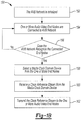
- Figure 1B depicts a flow chart of the AVB network 100 comprising the A/V end node 106a using the controller 107 to request being assigned the Talker (i.e., media clock master device 105).
- the Talker 106a may transmit the clock reference stream 108.
- the various operations shown in the flowchart diagram 150 appear to occur in a chronological sequence, at least some of the operations may occur in a different order, and some operations may be performed concurrently or not at all.
- the controller 107 may initialize the A/V end nodes 106 in communication on the network once a power-on request is received.
- the AVB network 100 may receive a message from the one or more A/V end nodes 106 requesting to communicate on the AVB network 100.
- the AVB network 100 may recognize the A/V end nodes 106 requesting to communicate on the network 100.
- the A/V end node 106 may be preconfigured as the Talker 106a and begin to transmit a clock reference stream to the one or more A/V end nodes 106 in operation 160.
- a device (not assigned as an A/V end node 106) in communication with the AVB network may be configured to allow an operator to select an A/V end node 106a-106n as the Talker, therefore assigning the Talker 106a as the media clock master device 105.
- the media clock master device 105 may transmit the clock reference stream 108 to the one or more A/V end nodes 106.
- the clock reference stream 108 is independent of any media data on the media stream 110 used by the A/V end node 106.
- the one or more A/V end nodes 106 may receive the clock reference stream 108 to synchronize the media data on the media stream 110 with the other A/V end nodes 106a-106n in communication on the network 100.
- FIG. 2A - 2B depict a packet format 200 of the timestamp for the clock reference stream 108 in the AVB network 100 according to an embodiment.
- the clock reference stream 108 allows for one or more clocks to be described within one stream. Therefore, one or more clock types may exist in the clock reference stream 108, which may be useful for describing related clocks.
- the one or more clock types in the clock reference stream 108 may include, but is not limited to, an audio sample timestamp 212, a video framesync timestamp 214, video line sync timestamp 216, and/or audio metadata 218.
- the timing information for the multiple clocks may be packed into one packet format 200; therefore the task of correlating and aligning the clocks may be simplified.
- the packet format 200 may also include, but is not limited to, standardized timestamp information, vendor specific 226, SMPTE time codes 220, and/or SMPTE sample code 222. There are most likely several other timing formats/types that may be used with the packet format of timestamps for the clock reference stream 108, however they are not explicitly enumerated in this embodiment.
- the audio sample timestamp 212 may be used to convey the sampling time of an audio sample clock.
- the video frame sync timestamp 214 may be used to convey the start of frame time of a video signal and/or the edge time of a frame sync clock.
- the video line sync timestamp 216 may be used to convey the start of line time of a video signal and/or the edge time of a line sync clock.
- the audio metadata 218 may be used to convey audio timing information usually embedded within a video transmission.
- the SMPTE time code 220 is formatted to convey television time code data per SMPTE standard ST 12-1:2008.
- the SMPTE sample code 222 may be used for keeping a sample count of video or audio data.
- Figure 2A depicts the packet format 200 for the clock reference stream 108 in the AVB network 100 which may include a top designator 202 and a side designator 204 to help a reader easily ascertain field widths and offsets.
- the packet format 200 may comprise one or more entry fields in the clock reference stream 108. The number of entry and order of the fields in the packet format 200 may remain constant for the life of the stream 108.
- the layout of the packet format 200 may include a reference type 206 field to enable the AVB network 100 to recognize the data type since one or more clocks may be described within one clock reference stream 108.
- Figure 2B depicts one or more references types that may be available for each entry on the clock reference stream 108.
- the reference type 206 may indicate the type of timestamp represented by the clock reference stream PDU including one or more timestamp entries and the format of the clock reference stream payload.
- the clock reference stream 108 may include a timestamp entry with a reference type 206 of Null 210.
- the Null 210 reference type 206 may be used when one or more of the entry fields do not include valid data at any given time for that timestamp on the clock reference stream 108.
- the Null 210 reference type 206 may take the place of the entry to indicate that no new information is present for that timestamp on the clock reference stream 108.
- the Null 210 reference type 206 may include a type field value 208of 0 16 which equates to a defined level of protocol.
- the type field value 208 associated with the reference type 206 may define the type field entry to a designate value. For example, a type field value 208 of 2 16 is placed in the reference type 206 field as an entry to designate that it is the video frame sync timestamp 214.
- Figure 3 depicts a timestamp diagram of an audio sample clock format 300 for the clock reference stream 108 in the AVB network 100 according to an embodiment.
- the reference type 206 may indicate that the timestamp is the audio sample timestamp 212 comprising the audio sample clock format 300.
- the audio sample clock format 300 may include a type field value 208 of 1 16 which is defined in the reference type 206 of an entry of a timestamp.
- the clock reference stream 108 may include a 64 bit timestamp in units of nanoseconds and including a maximum value of 2 64 - 1 ns.
- the clock reference stream 108 enables one or more timestamps to be supplied by the source of the media clock (i.e ., media clock master device 105) to allow media clock slaves (i.e., one or more A/V end nodes 106 assigned as Listeners) to lock quickly to the media clock by processing all timestamps within the clock reference stream PDU.
- media clock slaves i.e., one or more A/V end nodes 106 assigned as Listeners
- the end node 106 may continue to process all timestamps in the received clock reference stream 108, or the A/V end nodes 106 may process only a subset of the timestamps in the received clock reference stream 108 as necessary to maintain the lock while reducing timestamp processing overhead.
- the clock reference stream 108 may include the audio sample timestamp 212 used for conveying the sampling time of the audio sample clock.
- the audio sample clock format 300 may include one or more fields used for communicating audio sample time information.
- such fields of the audio sample clock format 300 may include, but is not limited to, an audio timestamp 302, a clock frequency 304, a clock multiplier 306, a timestamp interval 308 and a reserved section 310.
- the one or more fields may be configured to include an assigned length value of one or more octets.
- the audio timestamp 302 may include, but is not limited to, comprising a length of seven octets such that it may be large enough to last for a lifetime without starting over.
- the audio timestamp 302 may include a time value (e.g., 1000ns) taken from the same clock as the data associated with the audio sample.
- the A/V end node 106 may receive the time value to playback (i.e., playback time) the audio sample data at the same rate.
- the clock frequency 304 is a nominal frequency that enables the end node device 106 to determine an initial frequency value for clock recovery at the clock recovery circuit 120.
- the clock frequency 304 may improve the time it may take to lock the frequency and phase of the clock reference stream 108 at the end node device 106.
- the clock multiplier 306 is a predefined value based on the clock frequency and is used to adjust the nominal frequency for known frequencies that are offset ( e.g., enables the clock recovery circuit for backward compatibility related to frequencies represented in fraction values).
- the timestamp interval 308 identifies a number of audio samples between the timestamps. The timestamp interval 308 may be used to calculate the actual clock frequency value.
- the A/V end node 106 may receive the clock reference stream 108 comprising the audio timestamp 302 at the clock recovery circuit 120.
- the A/V end node 106 may calculate a first actual clock frequency based on the clock frequency 304 and clock multiplier 306.
- the clock frequency 304 and/or clock multiplier 306 provides the A/V end node a calculation for an initial input voltage to a circuit that generates the frequency to lock the Listener 106b-106n to the Talker 106a.
- the first actual clock frequency may enable the A/V end node 106 an initial frequency to improve timing of the locking of the frequency and phase of the clock reference stream 108.
- the A/V end node 106 may calculate the second actual clock frequency based on the timestamp interval 308 to lock the frequency and phase of the clock reference stream 108.
- the audio sample clock format 300 enables the AVB network 100 to distribute a common timing grid to one or more A/V end nodes 106 that may require synchronicity in both frequency and phase with the audio media data.
- the audio sample clock format 300 may provide the one or more A/V end nodes 106 with the packet format 200 encoding timing points across the AVB network 100.
- the AVB network 100 may deliver the audio sample timestamp 212 to one or more A/V end nodes 106 operating in that clock domain via the clock reference stream 108 with multicast addressing.
- the multicast addressing may provide different types of codes for the media stream 110 using the clock reference stream 108 which may transmit data to bridge different types of end nodes 106.
- the multicast addressing may allow the one or more A/V end nodes 106 in the network 100 to receive stream packets. For example, the Listener 106b-106n in the AVB network 100 may subscribe to an address in the multicast addressing.
- Figure 4A-4B depict the clock reference stream 108 including one or more information blocks 400 being communicated to one or more A/V end nodes 106 in the AVB network 100 according to an embodiment.
- the one or more information blocks 400 are a digital data transmission that includes a timestamp such that the receiver 103 is able to synchronize to the media clock master device 105.
- the one or more information blocks 400 only includes timing information, therefore media data is absent in the clock reference stream 108.
- the one or more information blocks 400 includes an AVTP common stream header, followed by a type specific header, then one or more timestamps.
- the stream header includes, but is not limited to, subtype data 402, stream identification 404, and a clock reference stream header 406.
- the clock reference stream header 406 includes several fields including, but not limited to, entries per block 408, number of blocks 410, sequence number 412, and a reserved section 414.
- the entries per block 408 is a number of timestamp, or other entries, correlated to each other temporally. For example, as shown in Figure 4A-4B , the entries per block would be assigned the value of two since there are always two entries (audio timestamp 212 and SMPTE time code 220) in every block 416, 418, 420.
- the number of blocks 410 is the number of blocks present in the packet. For this example, the number of blocks 410 field may be defined as three blocks (i.e., block 416, block 418, block 420) for the clock reference stream 108 as shown in Figure 4A-4B .
- the sequence number 412 allows the A/V end node 106 to determine when there is missing packets.
- the one or more information blocks 400 includes, but is not limited to, one or more audio sample timestamps 212.
- the one or more audio sample timestamps 212 may be paired with the respective video frame.
- the one or more audio sample timestamps 212 may be communicated to at least one A/V end node 106 (e.g. , video camera device) in communication with the AVB network 100.
- the clock reference stream 108 includes information block 416 comprising a type field 206 of type 0x01 representing the audio sample timestamp 212.
- the clock reference stream 108 may provide the sampling time of the audio sample timestamp 212 to the one or more A/V end nodes 106.
- the audio sample timestamp 212 entry may comprise data fields that include at least one of the audio timestamp 302, the clock frequency 304, the clock multiplier 306, the timestamp interval 308, and the reserved section 310.
- the audio timestamp 302 may include one 64 bit timestamp.
- the audio sample timestamp 212 may include an initial audio timestamp 302 at 1000ns.
- the clock frequency 304 may include the nominal frequency of the audio sample clock, which is set at 48,000 Hz in this example.
- the clock frequencies are nominal, thus, the actual frequency of the physical media clock may differ from this value by a small amount.
- the nominal frequency for a common audio use case is 48,000 Hz.
- the actual clock being transmitted may be 47,999 Hz based on the accuracy of a crystal or oscillator is that is generating the clock.
- Actual notice of the nominal frequency may be useful for clock recovery as the clock recovery circuitry 120 may adjust parameters that are optimized for certain frequency "families.” This condition may allow for a quicker locking to the actual frequency.
- the audio clock may include a pull-up or pull-down which offsets the physical clock from the nominal frequency by up to 0.1%.
- the one or more A/V end nodes 106 in the AVB network 100 may include recovery hardware which may adjust internal parameters to be able to handle such an offset.
- the clock multiplier 306 may contain a multiplier value based on the frequency value associated with the reference type (i.e., what type of timestamp it is such as any of the Null 210, audio sample timestamp 212, video frame sync timestamp 214, the video line sync timestamp 216, audio metadata 218, the SMPTE time code 220, the SMPTE sample code 222, reserved 224, and vender specific 226) of the clock reference stream 108.
- the audio sample clock format 300 may include the clock multiplier 306 of 1/1.001.
- the timestamp interval 308 may include a 16 bit field which indicates the number of samples between each timestamp given in the clock reference stream 108. For example, if the clock reference stream 108 includes a video frame sample, the timestamp interval 308 may include a 16 bit field which indicates the number of video frames between each video frame sync timestamp 214.
- the reserved section 310 may be set to zero on transmit and ignored when received.
- the reserved section 310 may be designated bits or fields which currently include no usage assigned to them.
- the reserved section 310 provides room to expand in future versions of the protocol, or to help align the bits of other fields so that they are more easily parsed by the receiving hardware.
- the clock reference stream 108 including information block 416 may deliver timestamps every eight samples (i.e., 166,667ns).
- the timestamp in information block 416 may be paired with a video comprising a set frame number 324, hour 326, minute 328, and second 330.
- the audio sample is formatted differently than the SMPTE defined time code, but contains all the needed information.
- the pairing of the SMPTE time code 220 reference type with an audio sample timestamp 212 is a way to correlate a timestamp derived from IEEE Std 802.1AS-2011.
- the audio sample may be paired with the SMPTE time code 220, including a type field 312 of type 0x05 representing a video.
- the audio sample is paired to the video at frame 125, hour 15, minute 25, and second 14.
- the SMPTE time code 220 may comprise additional fields including at least one of drop frame flag 314, color frame flag 316, field mark flag 318, binary group flags 320, user1-user7 fields 332, and a reserved field 334.
- the additional fields for the SMPTE time code 220 may enable SMPTE end nodes ( i.e., devices) to communicate over the A VB network 100.
- the clock reference stream 108 comprising information block 418 includes an audio timestamp 502 that is increased by 166,667ns to 167,667ns as expected based on the timestamps being delivered at every eight samples. Since the audio timestamp 502 is paired within the one video frame 324 (i.e., frame 125), the SMPTE time code 220 remains the same as in information block 416.
- the clock reference stream 108 comprising information block 420 includes an audio timestamp 602 that is increased by 166,667ns to 334,333ns. The increase by 166,667ns is as expected based on the timestamps being delivered at every eight samples.
- the audio timestamp 602 is paired with the video at a new frame number 624, hours 626, minutes 628, and seconds 630.
- the audio timestamp is paired with the SMPTE at frame 126, hour 15, minute 25, second 14.
Landscapes
- Engineering & Computer Science (AREA)
- Signal Processing (AREA)
- Multimedia (AREA)
- Computer Networks & Wireless Communication (AREA)
- Synchronisation In Digital Transmission Systems (AREA)
Claims (13)
- Einrichtung zum Kommunizieren mit einer Vielzahl von Audio/Video (A/V)-Endknoten (106b, 106c) in einem Audio Video Bridging (AVB)-Netzwerk (102), wobei die Einrichtung ein erster A/V-Endknoten (106a) ist,
wobei der erste A/V-Endknoten (106a) zu Folgendem konfiguriert ist:Übertragen eines Taktreferenzstroms (108), der eine Vielzahl von Zeitstempeln beinhaltet, die in einer Vielzahl von Informationsblöcken (400) in einem speziellen Paket beinhaltet ist, wobei jeder der Informationsblöcke einen Taktreferenzstrom-Header (406) beinhaltet, der ein Einträgepro-Block-Feld (408) und ein Blockanzahlfeld (410) beinhaltet, an eine Vielzahl von A/V-Endknoten (106b, 106c), die einen Medienstrom (110), der eine Vielzahl von Videoabtastungen und eine Vielzahl von Audioabtastungen beinhaltet, aneinander übertragen, wobei der Medienstrom (110) von dem Taktreferenzstrom (108) getrennt ist und jeder der Vielzahl von A/V-Endknoten (106b, 106c) angeordnet ist, um die Vielzahl von Videoabtastungen und die Vielzahl von Audioabtastungen zur Wiedergabe als Reaktion auf die Vielzahl von Zeitstempeln miteinander abzustimmen und zu synchronisieren;dadurch gekennzeichnet, dassdie Vielzahl von Zeitstempeln mindestens einen Audiozeitstempel und mindestens einen Videozeitstempel und/oder mindestens einen Zeitcode der Society of Motion Pictures and Television (SMPTE) beinhaltet; undder mindestens eine Audiozeitstempel mit mindestens einem Videozeitstempel oder mindestens einem SMPTE-Zeitcode gepaart ist, indem die Vielzahl von Zeitstempeln in der Vielzahl von Informationsblöcken in dem speziellen Paket eingefügt werden. - Einrichtung nach Anspruch 1, wobei einer oder mehrere der Vielzahl von Zeitstempeln eine Wiedergabezeit für die Vielzahl von A/V-Endknoten (106b, 106c) festlegen.
- Einrichtung nach Anspruch 1, wobei der erste A/V-Endknoten (106a) dazu konfiguriert ist, mindestens eines von Empfangen des Medienstroms (110) von der Vielzahl von A/V-Endknoten (106b, 106c) und Übertragen des Medienstroms (110) an die Vielzahl von A/V-Endknoten (106b, 106c) zu unterlassen.
- Einrichtung nach Anspruch 1, wobei jeder Zeitstempel einen Referenztyp beinhaltet, der einen in dem Medienstrom (110) beinhalteten Datentyp als eine von einer ersten Audioabtastung aus der Vielzahl von Audioabtastungen und einer ersten Videoabtastung aus der Vielzahl von Videoabtastungen definiert.
- Einrichtung nach Anspruch 4, wobei jeder Zeitstempel eine Taktfrequenz (304) beinhaltet, die eine Nennfrequenz eines Abtasttakts beinhaltet, die beliebigen der Vielzahl von A/V-Endknoten (106b, 106c) ermöglicht, die Vielzahl von Abtastungen wie von dem Medienstrom (110) empfangen wiederzugeben.
- Einrichtung nach Anspruch 5, wobei jeder Zeitstempel einen Taktmultiplikator (306) beinhaltet, um die Nennfrequenz eines zweiten A/V-Endknotens (106b, 106c), der den Medienstrom (110) von dem ersten A/V-Endknoten (106a) empfängt, einzustellen, um eine erste Ist-Taktfrequenz bereitzustellen.
- Einrichtung nach Anspruch 6, wobei jeder Zeitstempel ein Zeitstempelintervall (308) beinhaltet, das eine zweite Ist-Taktfrequenz des ersten A/V-Endknotens (106a) bestimmt.
- Einrichtung nach Anspruch 1, wobei der erste A/V-Endknoten (106a) durch eines von einem zweiten A/V-Endknoten (106b, 106c) oder einem eigenständigen Steuermodul als eine Medientakt-Hauptvorrichtung (105) festgelegt ist.
- Einrichtung nach Anspruch 1, wobei der erste A/V-Endknoten (106a) eine Versatzschaltung (116) beinhaltet, die dazu konfiguriert ist, einen Versatz zu erzeugen, der innerhalb des Taktreferenzstroms (108) beinhaltet ist, um eine Zeitverzögerung bereitzustellen, um zu ermöglichen, dass der Medienstrom (110) über das AVB-Netzwerk (102) an die Vielzahl von A/V-Endknoten (106b, 106c) übertragen wird.
- Einrichtung nach Anspruch 1, wobei der erste A/V-Endknoten (106a) ferner dazu konfiguriert ist, den Taktreferenzstrom (108) an die Vielzahl von A/V-Endknoten (106b, 106c) zu übertragen, um die Wiedergabe der Vielzahl von Videoabtastungen und der Vielzahl von Audioabtastungen in mindestens einer von Frequenz und Phase als Reaktion auf die Vielzahl von Zeitstempeln zu synchronisieren.
- Einrichtung nach Anspruch 1, wobei jeder A/V-Endknoten der Vielzahl von A/V-Endknoten (106b, 106c) einen ersten Eingang (120), um den Taktreferenzstrom (108) zu empfangen, und einen zweiten Eingang (122), um den Medienstrom (110) zu empfangen, beinhaltet.
- Computerprogrammprodukt, das in einem nichttransitorischen computerlesbaren Medium realisiert ist, das zum Kommunizieren mit einer Vielzahl von Audio/Video (A/V)-Endknoten (106b, 106c) in einem Audio Video Bridging (AVB)-Netzwerk (102) programmiert ist, wobei das Computerprogrammprodukt Anweisungen für Folgendes umfasst:Übertragen eines Taktreferenzstroms (108), der eine Vielzahl von Zeitstempeln beinhaltet, die in einer Vielzahl von Informationsblöcken (400) in einem speziellen Paket beinhaltet ist, wobei jeder der Informationsblöcke einen Taktreferenzstrom-Header (406) beinhaltet, der ein Einträgepro-Block-Feld (408) und ein Blockanzahlfeld (410) beinhaltet, an eine Vielzahl von A/V-Endknoten (106b, 106c); undÜbertragen eines Medienstroms (110), der eine Vielzahl von Videoabtastungen und eine Vielzahl von Audioabtastungen beinhaltet, von der Vielzahl von A/V-Endknoten (106b, 106c) aneinander, wobei der Medienstrom (110) von dem Taktreferenzstrom (108) getrennt ist und jeder der Vielzahl von A/V-Endknoten (106b, 106c) angeordnet ist, um die Vielzahl von Videoabtastungen und die Vielzahl von Audioabtastungen zur Wiedergabe als Reaktion auf die Vielzahl von Zeitstempeln miteinander abzustimmen und zu synchronisieren;dadurch gekennzeichnet, dassdie Vielzahl von Zeitstempeln mindestens einen Audiozeitstempel und mindestens einen Videozeitstempel und/oder mindestens einen Zeitcode der Society of Motion Pictures and Television (SMPTE) beinhaltet; undder mindestens eine Audiozeitstempel mit mindestens einem Videozeitstempel oder mindestens einem SMPTE-Zeitcode gepaart ist, indem die Vielzahl von Zeitstempeln in der Vielzahl von Informationsblöcken in dem speziellen Paket eingefügt wird.
- Computerprogrammprodukt nach Anspruch 12, wobei einer oder mehrere der Vielzahl von Zeitstempeln eine Wiedergabezeit für die Vielzahl von A/V-Endknoten (106b, 106c) festlegen.
Applications Claiming Priority (1)
| Application Number | Priority Date | Filing Date | Title |
|---|---|---|---|
| US14/266,490 US9553713B2 (en) | 2014-04-30 | 2014-04-30 | Method and system for transmitting clock reference streams with timestamps directly to audio/video end nodes in an audio/video bridging network |
Publications (2)
| Publication Number | Publication Date |
|---|---|
| EP2941006A1 EP2941006A1 (de) | 2015-11-04 |
| EP2941006B1 true EP2941006B1 (de) | 2021-10-13 |
Family
ID=53268596
Family Applications (1)
| Application Number | Title | Priority Date | Filing Date |
|---|---|---|---|
| EP15163479.7A Active EP2941006B1 (de) | 2014-04-30 | 2015-04-14 | Verfahren und system für taktreferenzströme |
Country Status (2)
| Country | Link |
|---|---|
| US (1) | US9553713B2 (de) |
| EP (1) | EP2941006B1 (de) |
Families Citing this family (16)
| Publication number | Priority date | Publication date | Assignee | Title |
|---|---|---|---|---|
| US10129839B2 (en) | 2014-12-05 | 2018-11-13 | Qualcomm Incorporated | Techniques for synchronizing timing of wireless streaming transmissions to multiple sink devices |
| KR101757528B1 (ko) * | 2015-04-14 | 2017-07-13 | 전자부품연구원 | 네트워크 기반 디스플레이의 부분 분할 동기화 방법 |
| CN107889205B (zh) | 2016-09-30 | 2021-08-20 | 华为技术有限公司 | 上行功率控制方法及装置 |
| CN108282856B (zh) | 2017-01-06 | 2023-05-16 | 华为技术有限公司 | 上行功率控制的方法和通信设备 |
| CN108632965B (zh) | 2017-03-24 | 2023-08-22 | 华为技术有限公司 | 一种上行发射功率控制的方法和设备 |
| CN109152029B (zh) | 2017-06-16 | 2024-04-16 | 华为技术有限公司 | 一种通信方法、网络设备及用户设备 |
| CN109803371B (zh) | 2017-11-17 | 2023-06-09 | 华为技术有限公司 | 一种通信处理方法和装置 |
| CN110311769B (zh) | 2018-02-14 | 2021-02-09 | 华为技术有限公司 | 一种确定时隙格式的方法、通信装置、计算机可读存储介质及设备 |
| CN110324125B (zh) | 2018-03-30 | 2022-08-19 | 华为技术有限公司 | 一种确定资源的方法及装置 |
| CN109246135B (zh) * | 2018-10-19 | 2020-08-07 | 视联动力信息技术股份有限公司 | 一种流媒体数据的获取方法和系统 |
| WO2020217286A1 (ja) * | 2019-04-22 | 2020-10-29 | 三菱電機株式会社 | 時刻同期システム、マスタ装置、スレーブ装置およびプログラム |
| WO2020231940A1 (en) * | 2019-05-12 | 2020-11-19 | Plantronics, Inc. | Ptp-based audio clock synchronization and alignment for acoustic echo cancellation in a conferencing system with ip-connected cameras, microphones and speakers |
| KR102275141B1 (ko) * | 2019-12-19 | 2021-07-07 | 현대오트론 주식회사 | 차량용 이더넷 네트워크에서 다수의 서브 제어기로부터 수신되는 다중 스트림 데이터를 동기화하여 출력하기 위한 차량 기기 제어 장치 및 방법 |
| KR20230158841A (ko) * | 2022-05-12 | 2023-11-21 | 현대자동차주식회사 | 차량 제어 시스템 및 방법 |
| US20250321905A1 (en) * | 2024-04-16 | 2025-10-16 | Microchip Technology Incorporated | System and Method to Efficiently Assist Time-Synchronous Media Streaming and Remote-Control Applications |
| WO2025221591A1 (en) * | 2024-04-16 | 2025-10-23 | Microchip Technology Incorporated | System and method to interface between time-synchronous data streaming and packetised data streaming |
Family Cites Families (8)
| Publication number | Priority date | Publication date | Assignee | Title |
|---|---|---|---|---|
| ES2745045T3 (es) | 2005-04-22 | 2020-02-27 | Audinate Pty Ltd | Red, dispositivo y método para transportar medios digitales |
| US8599310B2 (en) | 2010-12-14 | 2013-12-03 | Ati Technologies Ulc | Audio and video clock synchronization |
| US8699646B2 (en) * | 2011-04-18 | 2014-04-15 | Harman International Industries, Inc. | Media clock negotiation |
| US9088818B2 (en) * | 2011-06-21 | 2015-07-21 | Harman International Industries, Incorporated | Adaptive media delay matching |
| US20130003757A1 (en) | 2011-06-30 | 2013-01-03 | Harman International Industries, Incorporated | Syntonized communication system |
| US9516440B2 (en) * | 2012-10-01 | 2016-12-06 | Sonos | Providing a multi-channel and a multi-zone audio environment |
| US9426423B2 (en) * | 2012-11-01 | 2016-08-23 | Polycom, Inc. | Method and system for synchronizing audio and video streams in media relay conferencing |
| US20150128174A1 (en) * | 2013-11-04 | 2015-05-07 | Broadcom Corporation | Selecting audio-video (av) streams associated with an event |
-
2014
- 2014-04-30 US US14/266,490 patent/US9553713B2/en active Active
-
2015
- 2015-04-14 EP EP15163479.7A patent/EP2941006B1/de active Active
Non-Patent Citations (1)
| Title |
|---|
| None * |
Also Published As
| Publication number | Publication date |
|---|---|
| EP2941006A1 (de) | 2015-11-04 |
| US9553713B2 (en) | 2017-01-24 |
| US20150318977A1 (en) | 2015-11-05 |
Similar Documents
| Publication | Publication Date | Title |
|---|---|---|
| US9553713B2 (en) | Method and system for transmitting clock reference streams with timestamps directly to audio/video end nodes in an audio/video bridging network | |
| US8681772B2 (en) | Timing synchronization for networks with radio links | |
| KR102031268B1 (ko) | 시간-인식 디바이스들 사이에 시간 정보를 통신하는 방법 및 장치 | |
| EP1256197B1 (de) | Verteilung einer zeitreferenz über ein netzwerk | |
| EP2150062B1 (de) | Verbessertes Verfahren, System und Vorrichtung zur Synchronisierung von Signalen | |
| JP4987346B2 (ja) | ネットワークを介した時間同期化システムおよび方法 | |
| CN100388646C (zh) | 利于无线网状网络中同步的装置及相关方法 | |
| CN101459691B (zh) | 一种实现ieee1588协议中边界时钟的方法和系统 | |
| US8774287B2 (en) | Precise compensation of video propagation duration | |
| US10778359B2 (en) | Time synchronization method, programmable logic device, single board and network element | |
| JP6796233B2 (ja) | 映像切替システム | |
| WO2019053853A1 (ja) | 映像切替システム | |
| JP7283069B2 (ja) | 時刻同期経路選択装置、および、時刻同期経路選択方法 | |
| KR20070070299A (ko) | 레지덴셜 이더넷 시스템에서의 시간 동기화 방법 | |
| JP2012520592A (ja) | データパケットネットワークの通信ノードを同期させるために選択されたタイプを有する分散データを処理する方法、および関連するデバイス | |
| CN103201971A (zh) | 用于同步具有节点之间的聚合连接的分组交换网络的主时钟和从时钟的方法以及相关联的同步装置 | |
| CN105706383A (zh) | 时间同步的可插拔收发信机 | |
| WO2014083725A1 (ja) | 同期装置、同期システム、無線通信装置及び同期方法 | |
| CN102342051B (zh) | 用于通过经由至少一个时间分发协议分开传输第一和第二数据来同步时钟的方法和相关的系统及模块 | |
| JP6227888B2 (ja) | 通信システム、同期システム、通信方法 | |
| CN112636861A (zh) | 一种时钟同步方法、装置、设备及存储介质 | |
| Diarra et al. | Improved clock synchronization start-up time for Ethernet AVB-based in-vehicle networks | |
| US11876609B2 (en) | Time sync device, time sync method, and program | |
| KR101102089B1 (ko) | 물리 계층에서의 타임스탬핑 장치 및 그 방법 | |
| JP2010062992A (ja) | クロック同期方法及び通信システム |
Legal Events
| Date | Code | Title | Description |
|---|---|---|---|
| PUAI | Public reference made under article 153(3) epc to a published international application that has entered the european phase |
Free format text: ORIGINAL CODE: 0009012 |
|
| AK | Designated contracting states |
Kind code of ref document: A1 Designated state(s): AL AT BE BG CH CY CZ DE DK EE ES FI FR GB GR HR HU IE IS IT LI LT LU LV MC MK MT NL NO PL PT RO RS SE SI SK SM TR |
|
| AX | Request for extension of the european patent |
Extension state: BA ME |
|
| 17P | Request for examination filed |
Effective date: 20160226 |
|
| RBV | Designated contracting states (corrected) |
Designated state(s): AL AT BE BG CH CY CZ DE DK EE ES FI FR GB GR HR HU IE IS IT LI LT LU LV MC MK MT NL NO PL PT RO RS SE SI SK SM TR |
|
| STAA | Information on the status of an ep patent application or granted ep patent |
Free format text: STATUS: EXAMINATION IS IN PROGRESS |
|
| 17Q | First examination report despatched |
Effective date: 20200401 |
|
| GRAP | Despatch of communication of intention to grant a patent |
Free format text: ORIGINAL CODE: EPIDOSNIGR1 |
|
| STAA | Information on the status of an ep patent application or granted ep patent |
Free format text: STATUS: GRANT OF PATENT IS INTENDED |
|
| INTG | Intention to grant announced |
Effective date: 20210426 |
|
| GRAS | Grant fee paid |
Free format text: ORIGINAL CODE: EPIDOSNIGR3 |
|
| GRAA | (expected) grant |
Free format text: ORIGINAL CODE: 0009210 |
|
| STAA | Information on the status of an ep patent application or granted ep patent |
Free format text: STATUS: THE PATENT HAS BEEN GRANTED |
|
| AK | Designated contracting states |
Kind code of ref document: B1 Designated state(s): AL AT BE BG CH CY CZ DE DK EE ES FI FR GB GR HR HU IE IS IT LI LT LU LV MC MK MT NL NO PL PT RO RS SE SI SK SM TR |
|
| REG | Reference to a national code |
Ref country code: GB Ref legal event code: FG4D |
|
| REG | Reference to a national code |
Ref country code: CH Ref legal event code: EP |
|
| REG | Reference to a national code |
Ref country code: DE Ref legal event code: R096 Ref document number: 602015074052 Country of ref document: DE |
|
| REG | Reference to a national code |
Ref country code: IE Ref legal event code: FG4D |
|
| REG | Reference to a national code |
Ref country code: AT Ref legal event code: REF Ref document number: 1439034 Country of ref document: AT Kind code of ref document: T Effective date: 20211115 |
|
| REG | Reference to a national code |
Ref country code: LT Ref legal event code: MG9D |
|
| REG | Reference to a national code |
Ref country code: NL Ref legal event code: MP Effective date: 20211013 |
|
| REG | Reference to a national code |
Ref country code: AT Ref legal event code: MK05 Ref document number: 1439034 Country of ref document: AT Kind code of ref document: T Effective date: 20211013 |
|
| PG25 | Lapsed in a contracting state [announced via postgrant information from national office to epo] |
Ref country code: RS Free format text: LAPSE BECAUSE OF FAILURE TO SUBMIT A TRANSLATION OF THE DESCRIPTION OR TO PAY THE FEE WITHIN THE PRESCRIBED TIME-LIMIT Effective date: 20211013 Ref country code: LT Free format text: LAPSE BECAUSE OF FAILURE TO SUBMIT A TRANSLATION OF THE DESCRIPTION OR TO PAY THE FEE WITHIN THE PRESCRIBED TIME-LIMIT Effective date: 20211013 Ref country code: FI Free format text: LAPSE BECAUSE OF FAILURE TO SUBMIT A TRANSLATION OF THE DESCRIPTION OR TO PAY THE FEE WITHIN THE PRESCRIBED TIME-LIMIT Effective date: 20211013 Ref country code: BG Free format text: LAPSE BECAUSE OF FAILURE TO SUBMIT A TRANSLATION OF THE DESCRIPTION OR TO PAY THE FEE WITHIN THE PRESCRIBED TIME-LIMIT Effective date: 20220113 Ref country code: AT Free format text: LAPSE BECAUSE OF FAILURE TO SUBMIT A TRANSLATION OF THE DESCRIPTION OR TO PAY THE FEE WITHIN THE PRESCRIBED TIME-LIMIT Effective date: 20211013 |
|
| PG25 | Lapsed in a contracting state [announced via postgrant information from national office to epo] |
Ref country code: IS Free format text: LAPSE BECAUSE OF FAILURE TO SUBMIT A TRANSLATION OF THE DESCRIPTION OR TO PAY THE FEE WITHIN THE PRESCRIBED TIME-LIMIT Effective date: 20220213 Ref country code: SE Free format text: LAPSE BECAUSE OF FAILURE TO SUBMIT A TRANSLATION OF THE DESCRIPTION OR TO PAY THE FEE WITHIN THE PRESCRIBED TIME-LIMIT Effective date: 20211013 Ref country code: PT Free format text: LAPSE BECAUSE OF FAILURE TO SUBMIT A TRANSLATION OF THE DESCRIPTION OR TO PAY THE FEE WITHIN THE PRESCRIBED TIME-LIMIT Effective date: 20220214 Ref country code: PL Free format text: LAPSE BECAUSE OF FAILURE TO SUBMIT A TRANSLATION OF THE DESCRIPTION OR TO PAY THE FEE WITHIN THE PRESCRIBED TIME-LIMIT Effective date: 20211013 Ref country code: NO Free format text: LAPSE BECAUSE OF FAILURE TO SUBMIT A TRANSLATION OF THE DESCRIPTION OR TO PAY THE FEE WITHIN THE PRESCRIBED TIME-LIMIT Effective date: 20220113 Ref country code: NL Free format text: LAPSE BECAUSE OF FAILURE TO SUBMIT A TRANSLATION OF THE DESCRIPTION OR TO PAY THE FEE WITHIN THE PRESCRIBED TIME-LIMIT Effective date: 20211013 Ref country code: LV Free format text: LAPSE BECAUSE OF FAILURE TO SUBMIT A TRANSLATION OF THE DESCRIPTION OR TO PAY THE FEE WITHIN THE PRESCRIBED TIME-LIMIT Effective date: 20211013 Ref country code: HR Free format text: LAPSE BECAUSE OF FAILURE TO SUBMIT A TRANSLATION OF THE DESCRIPTION OR TO PAY THE FEE WITHIN THE PRESCRIBED TIME-LIMIT Effective date: 20211013 Ref country code: GR Free format text: LAPSE BECAUSE OF FAILURE TO SUBMIT A TRANSLATION OF THE DESCRIPTION OR TO PAY THE FEE WITHIN THE PRESCRIBED TIME-LIMIT Effective date: 20220114 Ref country code: ES Free format text: LAPSE BECAUSE OF FAILURE TO SUBMIT A TRANSLATION OF THE DESCRIPTION OR TO PAY THE FEE WITHIN THE PRESCRIBED TIME-LIMIT Effective date: 20211013 |
|
| REG | Reference to a national code |
Ref country code: DE Ref legal event code: R097 Ref document number: 602015074052 Country of ref document: DE |
|
| PG25 | Lapsed in a contracting state [announced via postgrant information from national office to epo] |
Ref country code: SM Free format text: LAPSE BECAUSE OF FAILURE TO SUBMIT A TRANSLATION OF THE DESCRIPTION OR TO PAY THE FEE WITHIN THE PRESCRIBED TIME-LIMIT Effective date: 20211013 Ref country code: SK Free format text: LAPSE BECAUSE OF FAILURE TO SUBMIT A TRANSLATION OF THE DESCRIPTION OR TO PAY THE FEE WITHIN THE PRESCRIBED TIME-LIMIT Effective date: 20211013 Ref country code: RO Free format text: LAPSE BECAUSE OF FAILURE TO SUBMIT A TRANSLATION OF THE DESCRIPTION OR TO PAY THE FEE WITHIN THE PRESCRIBED TIME-LIMIT Effective date: 20211013 Ref country code: EE Free format text: LAPSE BECAUSE OF FAILURE TO SUBMIT A TRANSLATION OF THE DESCRIPTION OR TO PAY THE FEE WITHIN THE PRESCRIBED TIME-LIMIT Effective date: 20211013 Ref country code: DK Free format text: LAPSE BECAUSE OF FAILURE TO SUBMIT A TRANSLATION OF THE DESCRIPTION OR TO PAY THE FEE WITHIN THE PRESCRIBED TIME-LIMIT Effective date: 20211013 Ref country code: CZ Free format text: LAPSE BECAUSE OF FAILURE TO SUBMIT A TRANSLATION OF THE DESCRIPTION OR TO PAY THE FEE WITHIN THE PRESCRIBED TIME-LIMIT Effective date: 20211013 |
|
| PLBE | No opposition filed within time limit |
Free format text: ORIGINAL CODE: 0009261 |
|
| STAA | Information on the status of an ep patent application or granted ep patent |
Free format text: STATUS: NO OPPOSITION FILED WITHIN TIME LIMIT |
|
| 26N | No opposition filed |
Effective date: 20220714 |
|
| PG25 | Lapsed in a contracting state [announced via postgrant information from national office to epo] |
Ref country code: AL Free format text: LAPSE BECAUSE OF FAILURE TO SUBMIT A TRANSLATION OF THE DESCRIPTION OR TO PAY THE FEE WITHIN THE PRESCRIBED TIME-LIMIT Effective date: 20211013 |
|
| PG25 | Lapsed in a contracting state [announced via postgrant information from national office to epo] |
Ref country code: SI Free format text: LAPSE BECAUSE OF FAILURE TO SUBMIT A TRANSLATION OF THE DESCRIPTION OR TO PAY THE FEE WITHIN THE PRESCRIBED TIME-LIMIT Effective date: 20211013 |
|
| REG | Reference to a national code |
Ref country code: CH Ref legal event code: PL |
|
| REG | Reference to a national code |
Ref country code: BE Ref legal event code: MM Effective date: 20220430 |
|
| PG25 | Lapsed in a contracting state [announced via postgrant information from national office to epo] |
Ref country code: MC Free format text: LAPSE BECAUSE OF FAILURE TO SUBMIT A TRANSLATION OF THE DESCRIPTION OR TO PAY THE FEE WITHIN THE PRESCRIBED TIME-LIMIT Effective date: 20211013 Ref country code: LU Free format text: LAPSE BECAUSE OF NON-PAYMENT OF DUE FEES Effective date: 20220414 Ref country code: LI Free format text: LAPSE BECAUSE OF NON-PAYMENT OF DUE FEES Effective date: 20220430 Ref country code: FR Free format text: LAPSE BECAUSE OF NON-PAYMENT OF DUE FEES Effective date: 20220430 Ref country code: CH Free format text: LAPSE BECAUSE OF NON-PAYMENT OF DUE FEES Effective date: 20220430 |
|
| PG25 | Lapsed in a contracting state [announced via postgrant information from national office to epo] |
Ref country code: BE Free format text: LAPSE BECAUSE OF NON-PAYMENT OF DUE FEES Effective date: 20220430 |
|
| PG25 | Lapsed in a contracting state [announced via postgrant information from national office to epo] |
Ref country code: IE Free format text: LAPSE BECAUSE OF NON-PAYMENT OF DUE FEES Effective date: 20220414 |
|
| PG25 | Lapsed in a contracting state [announced via postgrant information from national office to epo] |
Ref country code: IT Free format text: LAPSE BECAUSE OF FAILURE TO SUBMIT A TRANSLATION OF THE DESCRIPTION OR TO PAY THE FEE WITHIN THE PRESCRIBED TIME-LIMIT Effective date: 20211013 |
|
| P01 | Opt-out of the competence of the unified patent court (upc) registered |
Effective date: 20230527 |
|
| PG25 | Lapsed in a contracting state [announced via postgrant information from national office to epo] |
Ref country code: HU Free format text: LAPSE BECAUSE OF FAILURE TO SUBMIT A TRANSLATION OF THE DESCRIPTION OR TO PAY THE FEE WITHIN THE PRESCRIBED TIME-LIMIT; INVALID AB INITIO Effective date: 20150414 |
|
| PG25 | Lapsed in a contracting state [announced via postgrant information from national office to epo] |
Ref country code: MK Free format text: LAPSE BECAUSE OF FAILURE TO SUBMIT A TRANSLATION OF THE DESCRIPTION OR TO PAY THE FEE WITHIN THE PRESCRIBED TIME-LIMIT Effective date: 20211013 Ref country code: CY Free format text: LAPSE BECAUSE OF FAILURE TO SUBMIT A TRANSLATION OF THE DESCRIPTION OR TO PAY THE FEE WITHIN THE PRESCRIBED TIME-LIMIT Effective date: 20211013 |
|
| PG25 | Lapsed in a contracting state [announced via postgrant information from national office to epo] |
Ref country code: MT Free format text: LAPSE BECAUSE OF FAILURE TO SUBMIT A TRANSLATION OF THE DESCRIPTION OR TO PAY THE FEE WITHIN THE PRESCRIBED TIME-LIMIT Effective date: 20211013 |
|
| PGFP | Annual fee paid to national office [announced via postgrant information from national office to epo] |
Ref country code: DE Payment date: 20250319 Year of fee payment: 11 |
|
| PG25 | Lapsed in a contracting state [announced via postgrant information from national office to epo] |
Ref country code: TR Free format text: LAPSE BECAUSE OF FAILURE TO SUBMIT A TRANSLATION OF THE DESCRIPTION OR TO PAY THE FEE WITHIN THE PRESCRIBED TIME-LIMIT Effective date: 20211013 |
|
| PGFP | Annual fee paid to national office [announced via postgrant information from national office to epo] |
Ref country code: GB Payment date: 20260319 Year of fee payment: 12 |