EP2941009A1 - Anzeigevorrichtung - Google Patents
Anzeigevorrichtung Download PDFInfo
- Publication number
- EP2941009A1 EP2941009A1 EP13868385.9A EP13868385A EP2941009A1 EP 2941009 A1 EP2941009 A1 EP 2941009A1 EP 13868385 A EP13868385 A EP 13868385A EP 2941009 A1 EP2941009 A1 EP 2941009A1
- Authority
- EP
- European Patent Office
- Prior art keywords
- speaker
- mount
- section
- hole
- display device
- Prior art date
- Legal status (The legal status is an assumption and is not a legal conclusion. Google has not performed a legal analysis and makes no representation as to the accuracy of the status listed.)
- Granted
Links
Images












Classifications
-
- H—ELECTRICITY
- H04—ELECTRIC COMMUNICATION TECHNIQUE
- H04R—LOUDSPEAKERS, MICROPHONES, GRAMOPHONE PICK-UPS OR LIKE ACOUSTIC ELECTROMECHANICAL TRANSDUCERS; ELECTRIC HEARING AIDS; PUBLIC ADDRESS SYSTEMS
- H04R1/00—Details of transducers, loudspeakers or microphones
- H04R1/02—Casings; Cabinets ; Supports therefor; Mountings therein
- H04R1/025—Arrangements for fixing loudspeaker transducers, e.g. in a box, furniture
-
- H—ELECTRICITY
- H04—ELECTRIC COMMUNICATION TECHNIQUE
- H04N—PICTORIAL COMMUNICATION, e.g. TELEVISION
- H04N5/00—Details of television systems
- H04N5/64—Constructional details of receivers, e.g. cabinets or dust covers
- H04N5/642—Disposition of sound reproducers
-
- H—ELECTRICITY
- H04—ELECTRIC COMMUNICATION TECHNIQUE
- H04R—LOUDSPEAKERS, MICROPHONES, GRAMOPHONE PICK-UPS OR LIKE ACOUSTIC ELECTROMECHANICAL TRANSDUCERS; ELECTRIC HEARING AIDS; PUBLIC ADDRESS SYSTEMS
- H04R1/00—Details of transducers, loudspeakers or microphones
- H04R1/02—Casings; Cabinets ; Supports therefor; Mountings therein
- H04R1/028—Casings; Cabinets ; Supports therefor; Mountings therein associated with devices performing functions other than acoustics, e.g. electric candles
-
- H—ELECTRICITY
- H04—ELECTRIC COMMUNICATION TECHNIQUE
- H04R—LOUDSPEAKERS, MICROPHONES, GRAMOPHONE PICK-UPS OR LIKE ACOUSTIC ELECTROMECHANICAL TRANSDUCERS; ELECTRIC HEARING AIDS; PUBLIC ADDRESS SYSTEMS
- H04R5/00—Stereophonic arrangements
- H04R5/02—Spatial or constructional arrangements of loudspeakers
-
- H—ELECTRICITY
- H04—ELECTRIC COMMUNICATION TECHNIQUE
- H04R—LOUDSPEAKERS, MICROPHONES, GRAMOPHONE PICK-UPS OR LIKE ACOUSTIC ELECTROMECHANICAL TRANSDUCERS; ELECTRIC HEARING AIDS; PUBLIC ADDRESS SYSTEMS
- H04R2499/00—Aspects covered by H04R or H04S not otherwise provided for in their subgroups
- H04R2499/10—General applications
- H04R2499/15—Transducers incorporated in visual displaying devices, e.g. televisions, computer displays, laptops
Definitions
- the present technology relates to a technical field concerning a display device. Specifically, it relates to a technical field concerning a display device including a speaker unit that outputs sound and a display that outputs images, in which the speaker unit is mounted on a speaker mount section.
- Patent Literature 1 JP 2006-253948A
- a display device of a television receiver, a personal computer, or the like there has been one that is provided with a display having a display screen on which an image is displayed; outside the display, for example, beside or below the display, a speaker unit is mounted (for example, refer to Patent Literature 1).
- a speaker box is mounted below the display; in the speaker box, a pair of speaker units are mounted at a horizontally spaced positions.
- the speaker box is formed in a laterally long shape, and its inside is formed as a space.
- the pair of speaker units are mounted in the inner space of the speaker box.
- a space that serves as a passage of sound outputted from a sound output section of the speaker unit be a closed space, preventing sound leakage or air leakage from other spaces.
- a display device includes: a display configured to allow an image to be displayed on a display screen; a front board mounted on a front side of the display; a mount frame that is mounted on a rear surface side of the front board and includes a speaker mount section; a speaker bracket that is mounted on the speaker mount section and includes a sound output hole; and a speaker unit that is attached to the speaker bracket and includes a sound output section.
- the speaker mount section is provided with an insertion hole.
- the front board is provided with a mount hole superposed on the insertion hole.
- the speaker bracket is provided with a mount protrusion that is inserted in the insertion hole and the mount hole and is positioned with respect to the mount hole.
- the speaker bracket is provided with an annular sealing cushion located around the sound output section.
- the sealing cushion allows a passage of sound outputted from the sound output section to form a closed space.
- the speaker bracket be configured of a first mount member and a second mount member.
- the first mount member includes the mount protrusion and the sound output hole.
- the second mount member is attached to the first mount member from a rear surface side and includes an output hole, the output hole being superposed on the sound output hole.
- the sealing cushion is provided around the output hole of the second mount member, and the sealing cushion is pressed onto a rear surface of the first mount member.
- the sealing cushion is provided around the output hole of the second mount member, and the sealing cushion is pressed onto the rear surface of the first mount member. Thus, a closed space is formed between the first mount member and the second mount member.
- the sealing cushion be provided around the mount protrusion of the speaker bracket, and the sealing cushion be pressed onto the speaker mount section.
- the sealing cushion is provided around the mount protrusion of the speaker bracket, and the sealing cushion is pressed onto the speaker mount section. Thus, a closed space is formed between the speaker bracket and the speaker mount section.
- an annular blocking cushion that is pressed onto the speaker bracket be provided around the sound output section in a front surface of the speaker unit.
- the annular blocking cushion that is pressed onto the speaker bracket is provided around the sound output section in the front surface of the speaker unit. Thus, a closed space is formed between the speaker unit and the speaker bracket.
- the second mount member be provided with a pressing cushion pressed onto the speaker mount section.
- the second mount member is provided with the pressing cushion pressed onto the speaker mount section.
- a mounted state of the second mount member with respect to the speaker mount section becomes stable.
- a cover body be provided.
- the cover body is attached to the speaker mount section, covers the speaker bracket and the speaker unit, and retains the speaker unit from behind.
- the cover body is provided that is attached to the speaker mount section, covers the speaker bracket and the speaker unit, and retains the speaker unit from behind. Thus, the speaker unit is mounted stably.
- a cushion member that is pressed onto the speaker mount section be provided in a periphery of the cover body.
- the cushion member that is pressed onto the speaker mount section is provided in the periphery of the cover body. Thus, a closed space is formed by the cover body and the speaker mount section.
- a speaker control board that is configured to control the speaker unit be attached to the speaker mount section, and the speaker bracket be provided with a retaining protrusion that retains the speaker mount section.
- the speaker control board configured to control the speaker unit is attached to the speaker mount section, and the speaker bracket is provided with the retaining protrusion that retains the speaker control board.
- the speaker bracket is provided with the retaining protrusion that retains the speaker control board.
- a speaker control board that is configured to control the speaker unit be attached to the speaker mount section.
- the speaker control board and the speaker unit are connected by a connection cord, and the speaker bracket is provided with a cord holder that holds the connection cord.
- the speaker control board that is configured to control the speaker unit is attached to the speaker mount section.
- the speaker control board and the speaker unit are connected by the connection cord, and the speaker bracket is provided with the cord holder that holds the connection cord. Thus, little undesirable load from the connection cord is applied to the speaker unit.
- the second mount member be provided with a receiving section that is configured to restrict displacement of the first mount member in a front-rear direction with respect to the speaker mount section.
- the second mount member is provided with the receiving section that is configured to restrict the displacement of the first mount member in the front rear direction with respect to the speaker mount section. Thus, unintended displacement of the first mount member is restricted by the receiving section.
- the display device includes: the display configured to allow an image to be displayed on the display screen; the front board mounted on the front side of the display; the mount frame that is mounted on the rear surface side of the front board and includes the speaker mount section; the speaker bracket that is mounted on the speaker mount section and includes the sound output hole; and the speaker unit that is attached to the speaker bracket and includes the sound output section.
- the speaker mount section is provided with the insertion hole.
- the front board is provided with the mount hole superposed on the insertion hole.
- the speaker bracket is provided with the mount protrusion that is inserted in the insertion hole and the mount hole and is positioned with respect to the mount hole.
- the speaker bracket is provided with the annular sealing cushion located around the sound output section.
- the speaker bracket to which the speaker unit is attached is positioned with respect to the front board, and the sealing cushion allows a space that serves as the passage of sound outputted from the sound output section to be a closed space. Hence, it is possible to enhance positional accuracy of the speaker unit and to prevent sound leakage of sound outputted from the speaker unit and air leakage.
- the speaker bracket is configured of the first mount member and the second mount member.
- the first mount member includes the mount protrusion and the sound output hole.
- the second mount member is attached to the first mount member from the rear surface side and includes the output hole, the output hole being superposed on the sound output hole.
- the sealing cushion is provided around the output hole of the second mount member, and the sealing cushion is pressed onto the rear surface of the first mount member.
- the sealing cushion is provided around the mount protrusion of the speaker bracket, and the sealing cushion is pressed onto the speaker mount section.
- the annular blocking cushion that is pressed onto the speaker bracket is provided around the sound output section in the front surface of the speaker unit.
- the second mount member is provided with the pressing cushion pressed onto the speaker mount section.
- the second mount member is prevented from rattling with respect to the speaker mount section, allowing for sound output having good sound quality in the speaker unit.
- the cover body is provided that is attached to the speaker mount section, covers the speaker bracket and the speaker unit, and retains the speaker unit from behind.
- the cushion member that is pressed onto the speaker mount section is provided in the periphery of the cover body.
- the speaker control board that is configured to control the speaker unit is attached to the speaker mount section.
- the speaker bracket is provided with the retaining protrusion that retains the speaker control board.
- the speaker control board that is configured to control the speaker unit is attached to the speaker mount section.
- the speaker control board and the speaker unit are connected by the connection cord, and the speaker bracket is provided with the cord holder that holds the connection cord.
- connection cord little undesirable load from the connection cord is applied to the speaker unit. Hence, it is possible to ensure a stable mounted state of the speaker unit.
- the second mount member is provided with the receiving section that is configured to restrict displacement of the first mount member in the front-rear direction with respect to the speaker mount section.
- Embodiments that will be described below involve application of the display device according to the embodiment of the present technology to a television receiver that is configured to allow an image to be displayed on a display.
- a range of application of the present technology is not limited to a television receiver, and the present technology has a wide range of application to various display devices such as monitors used in a personal computer and so forth.
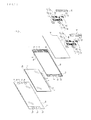
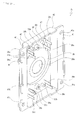
- a display device (a television receiver) 1 may be formed, for example, in a laterally long, flat, and substantially rectangular shape, and may include a display (a display panel) 2, a front board 3, and a backlight unit 4 (refer to Figs. 1 and 2 ).
- the display 2 is configured to allow an image to be displayed.
- the front board 3 is mounted on a front side of the display 2.
- the backlight unit 4 is mounted on a rear side of the display 2.
- the display 2 may be formed in a shape of a plate directed in a front-rear direction.
- a liquid crystal panel may be used as the display 2 for example.
- a region except for a periphery of a front surface of the display 2 may constitute a display screen 2e on which an image is displayed.
- laterally long drive boards 6, 6 may be connected via connection boards 5, 5, ....
- the connection boards 5 may have high flexibility.
- the drive boards 6, 6 may be located side by side horizontally.
- the front board 3 may be formed in a laterally long rectangular shape and may be made of a plate-shaped material directed in the front-rear direction, for example, transparent glass. It is to be noted that the front board 3 is not limited to a transparent material as long as the front board 3 allows an image displayed on the display 2 to be visibly recognizable. Both right and left sides of the front board 3 may constitute mount surface sections 7, 7, respectively. A region surrounded by both upper and lower ends and the mount surface sections 7, 7 of the front board 3 forms an image display region 3a facing the display 2.
- the mount surface section 7 may be provided with first mount holes 7a, 7a and a second mount hole 7b at vertically spaced positions.
- Part of the first mount holes 7a, 7a may be communicated with a sideward space.
- the first mount hole 7a may be formed over the entire mount surface section 7 from a left end to a right end.
- the second mount hole 7b may be located between the first mount holes 7a, 7a, and may have a smaller diameter than that of the first mount holes 7a, 7a.
- a mount frame 8 may be mounted on a rear surface side of the front board 3.
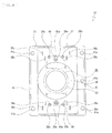
- the mount frame 8 may include speaker mount sections 9, 9 and connection bars 10, 10 (refer to Fig. 3 ).
- the speaker mount sections 9, 9 are located at horizontally spaced positions.
- the connection bars 10, 10 connect the speaker mount sections 9, 9.
- the speaker mount section 9 may be configured of a base surface section 11, a side surface section 12, and a holder section 13 (refer to Figs. 4 and 5 ).
- the base surface section 11 is directed in the front-rear direction.
- the side surface section 12 is protruded rearward from an outer end of the base surface section 11.
- the holder section 13 is provided in an inner end of the base surface section 11.
- protrusions 14, 14 may be provided on a rear surface side of the base surface section 11.
- the protrusions 14, 14 are protruded rearward from both right and left ends of the base surface section 11.
- Rear surfaces of the protrusions 14, 14 in the base surface section 11 may be formed as rear side surfaces 11 a, 11 a, respectively. Inner surfaces of the rear side surfaces 11 a, 11 a may be formed as inclined surfaces 11b, 11b that are inclined so as to be nearer to each other as they go forward. A surface between the inclined surfaces 11 a, 11 a may be formed as a front side surface 11c that is located forward of the rear side surfaces 11 a, 11 a.
- the base surface section 11 may be provided with first insertion holes 9a, 9a and a second insertion hole 9b at vertically spaced positions.
- the first insertion holes 9a, 9a may be formed over the entire base surface section 11 from a left end to a right end, and may have substantially same sizes as those of the first mount holes 7a, 7a of the mount surface section 7.
- the second insertion hole 9b may be located between the first insertion holes 9a, 9a, and may have a smaller diameter than those of the first insertion holes 9a, 9a.
- the second insertion hole 9b may have a substantially same size as that of the second mount hole 7b of the mount surface section 7.
- the second insertion hole 9b may be located in a portion in which the front side surface 11 c is formed.
- Both right and left ends in an upper edge of the first insertion holes 9a, 9a in the rear surface of the base surface section 11 may be formed as respective positioning edges 11d, 11d, ....
- positioning holes 11e, 11e may be formed on a lower side of the first insertion holes 9a, 9a in the rear surface of the base surface section 11.
- a positioning recess 11f may be formed sideward of the second insertion hole 9b in the rear surface of the base surface section 11.
- connecting protrusions 11g, 11g may be provided in both upper and lower ends of the base surface section 11.
- the connecting protrusions 11g, 11 g are protruded upward or downward.
- the protrusions 14, 14 each may be provided with screw holes 14a, 14a, ... at vertically spaced positions.
- the screw holes 14a, 14a, ... are opened rearward.
- the side surface section 12 may be provided with an engaging ridge 12a that is protruded inward.
- the engaging ridge 12a may be provided in a vertically extended state.
- the holder section 13 may be formed in a concave shape opened inward.
- connection bar 10 may be extended horizontally and may be formed in a concave shape opened inward (downward or upward).
- the connection bars 10, 10 may be attached to the speaker mount sections 9, 9 by connecting both right and left ends to the connecting protrusions 11f, 11f of the speaker mount sections 9, 9, respectively.
- the mount frame 8 may be formed by attaching the connection bars 10, 10 to the speaker mount sections 9, 9.
- the mount frame 8 may be mounted on a rear side of the front board 3.
- the first insertion holes 9a, 9a, ... of the mount frame 8 may be located directly behind the first mount holes 7a, 7a, ... of the front board 3, respectively;
- the second insertion holes 9b, 9b of the mount frame 8 may be located directly behind the second mount holes 7b, 7b of the front board 3, respectively.
- the holder sections 13, 13 of the speaker mount sections 9, 9 and the connection bars 10, 10 are formed in a concave shape opened inward. This allows a periphery of the display 2 to be inserted in these concave portions, allowing the display 2 to be held by the mount frame 8.
- the backlight unit 4 may include optical sheets, a diffusion plate, a back chassis, circuit boards, or the like, and a plurality of light sources, or the like.
- the optical sheets, the diffusion plate, the back chassis, the circuit boards, or the like are arranged in a front-rear direction.
- the plurality of light sources or the like are located below. Light emitted upward from the light sources may enter the diffusion plate, may be diffused by the diffusion plate, may be controlled by the optical sheets, and may enter the display 2 as backlight.
- the light sources for example, light emitting diodes may be used.
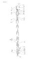
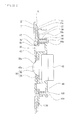
- first speaker structures 15, 15, ... and second speaker structures 16, 16 may be attached (refer to Figs. 7 and 8 ).
- the backlight unit 4 may be mounted so as to be opposed to the rear side of the display 2.
- the drive boards 6, 6 may be connected to the circuit boards of the backlight unit 4, with the connection boards 5, 5, ... folded below the backlight unit 4.
- the first speaker structures 15, 15 may be attached at vertically spaced positions, and the second speaker structure 16 may be attached between the first speaker structures 15, 15.
- the first speaker structure 15 on an upper side may be, for example, a structure of a speaker for a passive radiator.
- the first speaker 15 on a lower side may be, for example, a structure of a speaker for an accelerator (full-range).
- the second speaker structure 16 may be, for example, a structure of a speaker for tweeter.
- the display device 1 may be provided with an undepicted speaker structure for woofer.
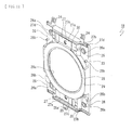
- the first speaker structure 15 may be configured of a first mount member 17, a second mount member 18, and a first speaker unit 19.
- the first mount member 17 and the second mount member 18 may constitute a first speaker bracket 20.
- the first mount member 17 may include a mount protrusion 21 and supported protrusions 22, 22, ... (refer to Figs. 9 and 10 ).
- the mount protrusion 21 is formed in a substantially annular shape directed substantially in the front-rear direction.
- the supported protrusions 22, 22, ... are provided in a rear surface of the mount protrusion 21.
- An inner hole of the mount protrusion 21 may be formed as a sound output hole 21a.
- the mount protrusion 21 may be provided with positioning protrusions 21b, 21b at vertically spaced positions. The positioning protrusions 21b, 21b are protruded rearward.
- At least part of the supported protrusion 22 may be protruded outward beyond the mount protrusion 21.
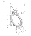
- the second mount member 18 may include a base surface section 23, retaining protrusions 24, 24, and a positioning piece 25 (refer to Figs. 11 and 12 ).
- An outer shape of the base surface section 23 is formed in a vertically long, substantially rectangular shape.
- the retaining protrusions 24, 24 are protruded upward from an upper surface of the base surface section 23.
- the positioning piece 25 is protruded downward from a lower surface of the base surface section 23.
- the base surface section 23 may be located rearward of other portion. The four corners may be provided as fastening sections 26, 26, ..., respectively.
- a portion between the fastening sections 26, 26 arranged horizontally may be provided as a projected section 27.
- a portion between the projected sections 27, 27 arranged vertically may be provided as a substantially annular pressing section 28.
- a screw insertion hole 26a may be formed in the fastening section 26.
- the fastening section 26 may be provided with a receiving section 26b that is protruded forward.
- a portion except for both right and left portions may constitute a planar section 27a that is directed in the front-rear direction.
- a portion on both right and left sides of the planar section 27a may constitute inclined sections 27b, 27b.
- the inclined sections 27b, 27b may be inclined so as to be nearer to each other as they go forward.
- the planar section 27a may be provided with a positioning hole 27c.
- the inclined sections 27b, 27b may be provided with positioning lugs 27d, 27d.
- a substantially annular sealing cushion 29 is provided in a front surface of the pressing section 28, a substantially annular sealing cushion 29 is provided.
- the sealing cushion 29 may be made of a rubber material or the like.
- An inner hole of the pressing section 28 may be formed as an output hole 28a.
- Pressing cushions 30, 30 may be provided on a front surface on both upper and lower ends of the base surface section 22.
- the pressing cushions 30, 30 may be formed in a horizontally extending shape.
- the sealing cushion 29 and the pressing cushions 30, 30 may be provided as, for example, part of the second mount member 18, by, for example, two-color molding.
- the retaining protrusions 24, 24 may be provided at horizontally spaced positions.
- the positioning piece 25 may be protruded from a center portion in a horizontal direction of the base surface section 22, and may include a positioning pin 25a that is protruded forward.
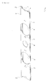
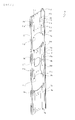
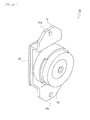
- the first speaker units 19, 19 of the first speaker structure 15, 15 may be partly different in shape for a passive radiator (refer to Figs. 13 and 14 ) and for an accelerator (refer to Figs. 15 and 16 ); otherwise, their basic configurations may be substantially same.
- the first speaker unit 19 may be configured of a main body 31, four attached pieces 32, 32, ..., and positioning pieces 33, 33.
- the four attached pieces 32, 32, ... are protruded radially from the main body 31.
- the positioning pieces 33, 33 may be protruded upward and downward from the main body 31, respectively.
- an annular blocking cushion 34 may be provided in a front surface of the main body 31 in a front surface of the main body 31 in a front surface of the main body 31, an annular blocking cushion 34 may be provided.
- the blocking cushion 34 may be made of a rubber material or the like.
- a portion inside the blocking cushion 34 may constitute a sound output section 31a.
- an insertion hole 32a may be formed.
- a positioning hole 33a may be formed.
- the second speaker structure 16 may be configured of a second speaker bracket 35 and a second speaker unit 36 (refer to Figs. 7 and 8 ).
- the second speaker bracket 35 may include a base surface section 37 and a mount protrusion 38 (refer to Figs. 17 and 18 ).
- the base surface section 37 is formed in a vertically long, substantially rectangular shape.
- the mount protrusion 38 is protruded forward from a center portion of the base surface section 37.
- the base surface section 37 may include a planar section 39, inclined sections 40, 40, and fastening sections 41, 41.
- the planar section 39 is directed in the front-rear direction.
- the inclined sections 40, 40 are formed continuously with both right and left sides of the planar section 39.
- the fastening sections 41, 41 are formed continuously with outer sides in a horizontal direction of the inclined sections 40, 40.
- attachment bosses 39a, 39a having screwing holes may be provided at vertically spaced positions.
- positioning axes 39b, 39b may be provided on right and left sides of the attachment boss 39a.
- the positioning axes 39b, 39b are protruded rearward.
- cord holders 39c, 39c, ... may be provided on an opposite side of the attachment boss 39a with the positioning axes 39b, 39b interposed therebetween.
- the cord holders 39c, 39c, ... are protruded rearward.
- respective screw insertion holes 41a, 41a may be formed in both upper and lower ends of the fastening section 41.
- a screwing hole 41b may be formed in a center portion in the vertical direction.
- One of the fastening sections 41 may be provided with a positioning protrusion 41c that is protruded forward.
- the positioning protrusion 38 may be protruded forward from the planar section 39, and may be formed in an annular shape. An inner hole of the positioning protrusion 38 may be formed as a sound output hole 38a.
- an annular sealing cushion 42 may be provided on a front surface of the base surface section 37.
- the sealing cushion 42 may be made of a rubber material or the like.
- the sealing cushion 42 may be located around the positioning protrusion 38.
- the sealing cushion 42 may be provided by two-color molding, similarly to the sealing cushion 29.
- the second speaker unit 36 may be configured of a main body 43 and attached pieces 44, 44 (refer to Figs. 19 and 20 ).
- the attached pieces 44, 44 are protruded upward and downward from the main body 43, respectively.
- an annular blocking cushion 45 may be provided in a front surface of the main body 43 .
- the blocking cushion 45 may be made of a rubber material or the like.
- a portion inside the blocking cushion 45 may constitute a sound output section 43 a.
- the attached piece 44 may be provided with an insertion hole 44a.
- Speaker control boards 46, 46 may be attached to upper ends of the speaker mount sections 9, 9 by screwing or the like (refer to Figs. 7 and 8 ).
- the speaker control board 46 may be connected to the first speaker units 19, 19, the second speaker unit 36, and a woofer speaker unit via connection cords 47, 47, ....
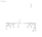
- connection cords 47, 47 may be arranged and held between the cord holders 39c, 39c, ... in the second speaker structure 16 (refer to Fig. 21 ).
- connection cords 47, 47 are arranged and held between the cord holders 39c, 39c, ... in the second speaker structure 16. Thus, little undesirable load from the connection cords 47, 47 is applied to the second speaker unit 36, making it possible to ensure a stable mounted state of the second speaker unit 36.
- the cord holders 39c, 39c, ... are provided in the second speaker bracket 35.
- a dedicated member for providing a holder to hold the connection cord 47 is unnecessary. This makes it possible to attain reduction in the number of components and reduction in manufacturing cost.
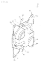
- Cover bodies 48, 48 may be attached to the respective speaker mount sections 9, 9 from a rear surface side (refer to Figs. 7 and 8 ).
- the cover body 48 may be formed in a vertically long, box-like shape opened forward.
- retaining protrusions 49, 49, ... may be provided at circumferentially spaced positions (refer to Figs. 22 and 23 ).
- the retaining protrusions 49, 49, ... are protruded forward.
- a screw hole 49a may be formed in a front end of the retaining protrusion 49.
- the screw hole 49a penetrates the front end of the retaining protrusion 49 in the front-rear direction.
- engaging pieces 48a, 48a may be provided at horizontally spaced positions (refer to Figs. 22 and 23 ). The engaging pieces 48, 48 are protruded upward.
- a cushion member 50 may be bonded to a front surface in the periphery of the cover body 48.
- the cushion member 50 may be made of a rubber material or the like.
- an undepicted back cover may be attached from behind by screwing or the like. Both right and left ends of the back cover may be engaged with the respective engaging ridges 12a, 12a that are provided in the side surface section 12 of the mount frame 8.
- a stand 51 may be attached to a lower end of the backlight unit 4 (refer to Fig. 1 ). The stand 51 may ensure a stable installation state of the display device 1 on a desk or the like.
- the first mount member 17 is mounted from behind on the speaker mount section 9 of the mount frame 8 (refer to Fig. 24 ).
- the mount protrusion 21 is inserted in the first mount hole 7a through the first insertion hole 9a.
- the first mount member 17 is positioned with respect to the first insertion hole 7a.
- the supported protrusions 22, 22, ... of the first mount member 17 are engaged with the rear surface of the base surface section 11.
- the first mount member 17 is positioned in the front-rear direction with respect to the speaker mount section 9.
- the second mount member 18 is mounted on the speaker mount section 9 and the first mount member 17 (refer to Fig. 25 ).
- the positioning lugs 27d, 27d and the positioning pin 25a are engaged with the positioning edges 11d, 11d and the positioning hole 11e, respectively.
- the second mount member 18 is positioned with respect to the speaker mount section 9.
- the positioning protrusions 21b, 21b are inserted in the respective positioning holes 27c, 27c.
- the second mount member 18 is positioned with respect to the first mount member 17.
- the sealing cushion 29 is pressed onto and adheres to a rear surface in the mount protrusion 21 of the first mount member 17, while the pressing cushions 30, 30 are pressed onto and adheres to the rear surface of the base surface section 11.
- the first speaker unit 19 is mounted from behind on the second mount member 18 (refer to Figs. 26 and 27 ).
- the positioning pins 25a, 25a are inserted in the respective positioning holes 33a, 33a formed in the positioning pieces 33, 33.
- the first speaker unit 19 is positioned with respect to the second mount member 18.
- the attached pieces 32, 32, ... are in contact with rear surfaces of the respective fastening sections 26, 26, ... of the second mount member 18, and the insertion holes 32a, 32a, ... are superposed on the respective screw insertion holes 26a, 26a, ....
- the sealing cushion 34 is pressed onto and adheres to a rear surface in the pressing section 28 of the second mount member 18.
- the second speaker bracket 35 is mounted from behind on the speaker mount section 9 of the mount frame 8 (refer to Fig. 28 ).
- the mount protrusion 38 is inserted in the second mount hole 7b through the second insertion hole 9b.
- the second speaker bracket 35 is positioned with respect to the second insertion hole 7b.
- the sealing cushion 42 of the second speaker bracket 35 is pressed onto and adheres to the rear surface of the base surface section 11.
- the second speaker bracket 35 is positioned in the front-rear direction with respect to the speaker mount section 9.
- the second speaker unit 36 is mounted from behind on the second speaker bracket 35 (refer to Figs. 29 and 30 ).
- the attached pieces 44, 44 are in contact with the respective attachment bosses 39a, 39a.
- Attachment screws 100, 100 are inserted in the respective insertion holes 44a, 44a and screwed with the attachment bosses 39a, 39a.
- the second speaker unit 36 is attached to the second speaker unit 36.
- the sealing cushion 45 is pressed onto and adheres to a rear surface in the mount protrusion 38 of the second speaker bracket 35.
- the cover body 48 is mounted from behind on the speaker mount section 9 (refer to Fig. 31 ).
- the speaker control board 46 is mounted on the speaker mount section 9 before the first speaker structure 15 on the upper side is mounted on the speaker mount section 9.
- the speaker control board 46 is retained by the retaining protrusions 24, 24 of the second mount member 18 in a state in which the second mount member 18 in the first speaker structure 15 on the upper side is mounted on the speaker mount section 9.
- the cushion member 50 that is pressed onto the speaker mount section 9 is provided in the periphery of the cover body 48.
- a closed space is formed by the cover body 48 and the speaker mount section 9. Accordingly, leakage of sound outputted from the first speaker units 19, 19, ... and the second speaker units 36, 36 is prevented, making it possible to attain enhanced sound quality.
- the cover body 48 is mounted on the speaker mount section 9, with the engaging pieces 48a, 48a engaged with part of the speaker mount section 9.
- the fastening sections 26, 26, ... of the second mount member 18, 18, the attached pieces 44, 44, ... of the second speaker unit 36, and the speaker control board 46 are retained by the retaining protrusions 49, 49, ....
- respective second attachment screws 200, 200, ... are inserted.
- the second attachment screws 200, 200, ... are inserted through the screw insertion holes 26a, 26a, ... formed in the fastening sections 26, 26, ... of the second mount member 18, and are screwed with the screw holes 14a, 14a, ... of the speaker mount section 9.
- the first speaker structure 15 is attached to the speaker mount section 9.
- other second attachment screws 200, 200, ... are inserted through the insertion holes 44a, 44a, ... formed in the attached pieces 44, 44, ... of the second speaker unit 36 and the screw insertion holes 41a, 41a, ... formed in the fastening sections 41, 41, ...
- the second speaker structure 16 is attached to the speaker mount section 9. Furthermore, still other second attachment screws 200, 200, ... are inserted through the speaker control board 46, and are screwed with the screw holes 14a, 14a, ... of the speaker mount section 9. Thus, the speaker control board 46 is attached to the speaker mount section 9.
- the cover body 48 is attached to the speaker mount section 9, and the first speaker structures 15, 15 and the second speaker structure 16 are attached to the speaker mount section 9.
- the mount protrusions 21, 21 of the first mount members 17, 17 and the sound output section 31a of the first speaker unit 19 are mounted in the respective first mount holes 7a, 7a of the front board 3, while the mount protrusion 38 of the second speaker bracket 35 and the sound output section 43a of the second speaker unit 36 are mounted in the second mount hole 7b of the front board 3.
- vibration due to sound pressure may be generated, and the vibration thus generated may be transmitted to the first mount member 17.
- the receiving sections 26b, 26b, ... of the second mount member 18 are located in proximity thereto.
- the first speaker bracket 20 is provided with the mount protrusion 21 that is positioned with respect to the first mount hole 7a of the front board 3, and the annular sealing cushion 29 is provided around the mount protrusion 21.
- the second speaker bracket 35 is provided with the mount protrusion 38 that is positioned with respect to the second mount hole 7b of the front board 3, and the annular sealing cushion 42 is provided around the mount protrusion 38.
- the first speaker bracket 20 or the second speaker bracket 35 to which the first speaker unit 19 or the second speaker unit 36 is attached is positioned with respect to the front board 3.
- the sealing cushions 29, 42 allow the space that serves as the passage of sound outputted from the sound output sections 31a, 43 a to be a closed space. This makes it possible to enhance positional accuracy of the first speaker unit 19 and the second speaker unit 36, and to prevent sound leakage of sound outputted from the first speaker unit 19 and the second speaker unit 36 and air leakage.
- the first speaker bracket 20 is configured of the first mount member 17 and the second mount member 18.
- the sealing cushion 29 is provided around the output hole 28a of the second mount member 18. The sealing cushion 29 is pressed onto the rear surface of the first mount member 17.
- the sealing cushion 42 is provided around the mount protrusion 38 of the second speaker bracket 35.
- the sealing cushion 42 is pressed onto the speaker mount section 9.
- annular blocking cushions 34, 45 are provided around the sound output sections 31a, 43a in the front surfaces of the first speaker unit 19 and the second speaker unit 36.
- the annular blocking cushions 34, 45 are pressed onto the first speaker bracket 20 or the second speaker bracket 35.
- annular sealing cushion 29 is provided around the mount protrusion 21 of the second mount member 18 in the first speaker bracket 20.
- the annular sealing cushion 29 is pressed onto the rear surface of the speaker mount section 9. It is therefore possible to prevent sound leakage and air leakage from except the first mount hole 7a, allowing for sound output having good sound quality in the first speaker unit 19.
- the pressing cushions 30, 30 are provided in the second mount member 18.
- the pressing cushions 30, 30 are pressed onto the rear surface of the speaker mount section 9. Accordingly, the second mount member 18 is prevented from rattling with respect to the speaker mount section 9, allowing for sound output having good sound quality in the first speaker unit 19.
- cover body 48 is provided that is attached to the speaker mount section 9, covers the first speaker structure 15, 15, and retains the first speaker unit 19 from behind. Accordingly, a stable mounted state of the first speaker unit 19 is ensured, allowing for sound output having good sound quality in the first speaker unit 19.
- the present technology may have the following configurations.
Landscapes
- Engineering & Computer Science (AREA)
- Signal Processing (AREA)
- Physics & Mathematics (AREA)
- Acoustics & Sound (AREA)
- Multimedia (AREA)
- Details Of Audible-Bandwidth Transducers (AREA)
- Fittings On The Vehicle Exterior For Carrying Loads, And Devices For Holding Or Mounting Articles (AREA)
- Devices For Indicating Variable Information By Combining Individual Elements (AREA)
Applications Claiming Priority (2)
| Application Number | Priority Date | Filing Date | Title |
|---|---|---|---|
| JP2012289074 | 2012-12-28 | ||
| PCT/JP2013/084068 WO2014103871A1 (ja) | 2012-12-28 | 2013-12-19 | 表示装置 |
Publications (3)
| Publication Number | Publication Date |
|---|---|
| EP2941009A1 true EP2941009A1 (de) | 2015-11-04 |
| EP2941009A4 EP2941009A4 (de) | 2016-09-14 |
| EP2941009B1 EP2941009B1 (de) | 2017-11-01 |
Family
ID=51020958
Family Applications (1)
| Application Number | Title | Priority Date | Filing Date |
|---|---|---|---|
| EP13868385.9A Active EP2941009B1 (de) | 2012-12-28 | 2013-12-19 | Anzeigevorrichtung |
Country Status (7)
| Country | Link |
|---|---|
| US (1) | US10136203B2 (de) |
| EP (1) | EP2941009B1 (de) |
| JP (1) | JP6325456B2 (de) |
| CN (1) | CN104871555B (de) |
| BR (1) | BR112015014834A2 (de) |
| RU (1) | RU2645014C2 (de) |
| WO (1) | WO2014103871A1 (de) |
Families Citing this family (11)
| Publication number | Priority date | Publication date | Assignee | Title |
|---|---|---|---|---|
| CN107949878B (zh) * | 2015-09-01 | 2021-12-21 | 株式会社电装电子 | 发声器 |
| US10129646B2 (en) | 2016-03-28 | 2018-11-13 | Lg Display Co., Ltd. | Panel vibration type sound generating display device |
| KR101817103B1 (ko) * | 2016-06-30 | 2018-01-10 | 엘지디스플레이 주식회사 | 패널 진동형 음향 발생 표시 장치 |
| KR102373433B1 (ko) * | 2017-04-29 | 2022-03-10 | 엘지디스플레이 주식회사 | 표시 장치 |
| KR102573519B1 (ko) * | 2018-12-04 | 2023-09-04 | 삼성전자주식회사 | 스피커 모듈을 포함하는 전자 장치 |
| JPWO2020137177A1 (ja) * | 2018-12-26 | 2021-11-18 | ソニーグループ株式会社 | 表示装置 |
| KR102679871B1 (ko) * | 2019-04-03 | 2024-06-28 | 엘지디스플레이 주식회사 | 표시장치 |
| KR102711119B1 (ko) * | 2019-05-10 | 2024-09-27 | 삼성디스플레이 주식회사 | 표시장치 |
| KR102647154B1 (ko) | 2019-12-31 | 2024-03-14 | 삼성전자주식회사 | 디스플레이 장치 |
| CN213906837U (zh) * | 2020-11-30 | 2021-08-06 | 瑞声光电科技(常州)有限公司 | 一种扬声器箱 |
| CN121816756A (zh) * | 2023-09-12 | 2026-04-07 | 哈曼国际工业有限公司 | 扬声器箱和电子装置 |
Family Cites Families (28)
| Publication number | Priority date | Publication date | Assignee | Title |
|---|---|---|---|---|
| GB1124412A (en) * | 1966-11-02 | 1968-08-21 | Joseph John Montanaro | Waterproof radio receiver |
| CN1163537A (zh) * | 1996-04-09 | 1997-10-29 | Lg电子株式会社 | 具有夹持住喇叭的机构的视频显示装置 |
| BR9700245A (pt) * | 1996-04-09 | 1998-10-27 | Lg Electronics Inc | Aparelho de exibição de vídeo |
| JP2002165286A (ja) * | 2000-11-24 | 2002-06-07 | Matsushita Electric Ind Co Ltd | スピーカー防振装置 |
| JP2002252892A (ja) * | 2001-02-26 | 2002-09-06 | Matsushita Electric Ind Co Ltd | 映像表示機器のスピーカー保持装置 |
| CN2481062Y (zh) * | 2001-05-25 | 2002-03-06 | 厦门华侨电子企业有限公司 | 一种带音箱的电视机 |
| US6999595B2 (en) | 2002-05-30 | 2006-02-14 | International Business Machines Corporation | Slide-on speaker assembly |
| KR100946444B1 (ko) * | 2002-08-02 | 2010-03-10 | 소니 주식회사 | 평면형 화상 표시 장치 |
| JP2004363832A (ja) * | 2003-06-03 | 2004-12-24 | Sony Corp | 表示装置 |
| JP2005080173A (ja) * | 2003-09-03 | 2005-03-24 | Sony Corp | 電子機器及びスピーカ装置 |
| US8103033B2 (en) * | 2004-09-01 | 2012-01-24 | Bose Corporation | Audio system for portable device |
| JP4086823B2 (ja) * | 2004-09-03 | 2008-05-14 | Necアクセステクニカ株式会社 | パネル型スピーカ、スピーカ一体型ディスプレイ及び電子装置 |
| JP2006106272A (ja) | 2004-10-04 | 2006-04-20 | Sony Corp | 表示装置 |
| JP4306627B2 (ja) | 2005-03-09 | 2009-08-05 | ソニー株式会社 | バスレフ型スピーカー装置,スピーカーボックス及び画像表示装置 |
| JP2006345292A (ja) * | 2005-06-09 | 2006-12-21 | Toshiba Corp | スピーカ装置及びその音響出力方法及び映像表示装置 |
| JP2006345294A (ja) * | 2005-06-09 | 2006-12-21 | Toshiba Corp | 映像表示装置 |
| JP4528672B2 (ja) * | 2005-06-09 | 2010-08-18 | 株式会社東芝 | 映像表示装置 |
| KR100813734B1 (ko) * | 2005-09-05 | 2008-03-13 | 엘지전자 주식회사 | 영상표시기기의 하울링 방지구조 |
| JP4390760B2 (ja) | 2005-09-30 | 2009-12-24 | シャープ株式会社 | スピーカ装置及び表示装置 |
| JP4572828B2 (ja) * | 2005-12-08 | 2010-11-04 | ソニー株式会社 | 画像表示装置 |
| CN2884742Y (zh) * | 2006-02-18 | 2007-03-28 | 康佳集团股份有限公司 | 平板电视 |
| TW200819878A (en) | 2006-10-19 | 2008-05-01 | Hannspree Inc | sealing mechanism of flat panel display |
| JP5070840B2 (ja) * | 2006-12-29 | 2012-11-14 | ソニー株式会社 | スピーカ付表示装置 |
| CN101785321A (zh) | 2007-08-22 | 2010-07-21 | 富士通株式会社 | 扬声器的安装构造以及平板显示器 |
| JP4199292B1 (ja) * | 2007-12-28 | 2008-12-17 | オリオン電機株式会社 | 表示装置 |
| JP5040854B2 (ja) * | 2008-08-11 | 2012-10-03 | ソニー株式会社 | 電子機器 |
| JP2012191529A (ja) * | 2011-03-11 | 2012-10-04 | Funai Electric Co Ltd | スピーカ取付け構造 |
| KR101383718B1 (ko) * | 2012-10-10 | 2014-04-10 | 현대자동차(주) | 차량의 외장에어백 쿠션 |
-
2013
- 2013-12-19 EP EP13868385.9A patent/EP2941009B1/de active Active
- 2013-12-19 WO PCT/JP2013/084068 patent/WO2014103871A1/ja not_active Ceased
- 2013-12-19 BR BR112015014834A patent/BR112015014834A2/pt not_active Application Discontinuation
- 2013-12-19 RU RU2015124050A patent/RU2645014C2/ru not_active IP Right Cessation
- 2013-12-19 JP JP2014554377A patent/JP6325456B2/ja active Active
- 2013-12-19 US US14/654,261 patent/US10136203B2/en active Active
- 2013-12-19 CN CN201380067138.7A patent/CN104871555B/zh active Active
Also Published As
| Publication number | Publication date |
|---|---|
| CN104871555B (zh) | 2018-11-09 |
| EP2941009B1 (de) | 2017-11-01 |
| CN104871555A (zh) | 2015-08-26 |
| BR112015014834A2 (pt) | 2017-07-11 |
| WO2014103871A1 (ja) | 2014-07-03 |
| EP2941009A4 (de) | 2016-09-14 |
| JP6325456B2 (ja) | 2018-05-16 |
| RU2645014C2 (ru) | 2018-02-15 |
| US10136203B2 (en) | 2018-11-20 |
| JPWO2014103871A1 (ja) | 2017-01-12 |
| RU2015124050A (ru) | 2017-02-01 |
| US20150358706A1 (en) | 2015-12-10 |
Similar Documents
| Publication | Publication Date | Title |
|---|---|---|
| EP2941009B1 (de) | Anzeigevorrichtung | |
| US9955592B2 (en) | Display device | |
| JP5928111B2 (ja) | 表示装置 | |
| US8915606B2 (en) | Display device | |
| CN106598178B (zh) | 交互智能平板 | |
| US20150304599A1 (en) | Display device | |
| US7898798B2 (en) | Heat dissipating structure for electronic component and display device | |
| US20100053912A1 (en) | Display apparatus | |
| JP4212062B1 (ja) | 液晶表示パネル | |
| US20140063351A1 (en) | Television receiver and electronic device | |
| US20140340587A1 (en) | Display device and television receiver | |
| EP3255624B1 (de) | Anzeigevorrichtung | |
| JP2009086276A (ja) | 画像表示装置とその支持体構造 | |
| US20130016863A1 (en) | Loudspeaker structure for flat display | |
| KR20220054997A (ko) | 디스플레이 장치 | |
| JP2019082535A (ja) | 表示装置 | |
| JP6557869B2 (ja) | 表示装置、および、表示装置に用いられる背面板 | |
| JP2009086643A (ja) | 画像表示装置とその支持体構造 | |
| JP2009086275A (ja) | 画像表示装置 | |
| JP2014016564A (ja) | 表示装置 | |
| JP7396925B2 (ja) | 電子機器 | |
| JP5097851B2 (ja) | 薄型表示装置用の電源基板及びそれを用いた薄型表示装置 | |
| JP6180751B2 (ja) | 電子機器 | |
| KR102091113B1 (ko) | 슬림형 대화면 시현기 | |
| CN210467145U (zh) | 一种显示装置 |
Legal Events
| Date | Code | Title | Description |
|---|---|---|---|
| PUAI | Public reference made under article 153(3) epc to a published international application that has entered the european phase |
Free format text: ORIGINAL CODE: 0009012 |
|
| 17P | Request for examination filed |
Effective date: 20150616 |
|
| AK | Designated contracting states |
Kind code of ref document: A1 Designated state(s): AL AT BE BG CH CY CZ DE DK EE ES FI FR GB GR HR HU IE IS IT LI LT LU LV MC MK MT NL NO PL PT RO RS SE SI SK SM TR |
|
| AX | Request for extension of the european patent |
Extension state: BA ME |
|
| DAX | Request for extension of the european patent (deleted) | ||
| A4 | Supplementary search report drawn up and despatched |
Effective date: 20160816 |
|
| RIC1 | Information provided on ipc code assigned before grant |
Ipc: H04R 5/02 20060101ALI20160809BHEP Ipc: H04N 5/64 20060101ALI20160809BHEP Ipc: H04R 1/02 20060101AFI20160809BHEP |
|
| RIC1 | Information provided on ipc code assigned before grant |
Ipc: H04R 1/02 20060101AFI20170310BHEP Ipc: H04N 5/64 20060101ALI20170310BHEP Ipc: H04R 5/02 20060101ALI20170310BHEP |
|
| GRAP | Despatch of communication of intention to grant a patent |
Free format text: ORIGINAL CODE: EPIDOSNIGR1 |
|
| INTG | Intention to grant announced |
Effective date: 20170424 |
|
| GRAS | Grant fee paid |
Free format text: ORIGINAL CODE: EPIDOSNIGR3 |
|
| RAP1 | Party data changed (applicant data changed or rights of an application transferred) |
Owner name: SATURN LICENSING LLC |
|
| GRAA | (expected) grant |
Free format text: ORIGINAL CODE: 0009210 |
|
| AK | Designated contracting states |
Kind code of ref document: B1 Designated state(s): AL AT BE BG CH CY CZ DE DK EE ES FI FR GB GR HR HU IE IS IT LI LT LU LV MC MK MT NL NO PL PT RO RS SE SI SK SM TR |
|
| REG | Reference to a national code |
Ref country code: GB Ref legal event code: FG4D |
|
| REG | Reference to a national code |
Ref country code: CH Ref legal event code: EP Ref country code: AT Ref legal event code: REF Ref document number: 943130 Country of ref document: AT Kind code of ref document: T Effective date: 20171115 |
|
| REG | Reference to a national code |
Ref country code: IE Ref legal event code: FG4D |
|
| REG | Reference to a national code |
Ref country code: FR Ref legal event code: PLFP Year of fee payment: 5 |
|
| REG | Reference to a national code |
Ref country code: DE Ref legal event code: R096 Ref document number: 602013028949 Country of ref document: DE |
|
| REG | Reference to a national code |
Ref country code: NL Ref legal event code: FP |
|
| REG | Reference to a national code |
Ref country code: LT Ref legal event code: MG4D |
|
| REG | Reference to a national code |
Ref country code: AT Ref legal event code: MK05 Ref document number: 943130 Country of ref document: AT Kind code of ref document: T Effective date: 20171101 |
|
| PG25 | Lapsed in a contracting state [announced via postgrant information from national office to epo] |
Ref country code: NO Free format text: LAPSE BECAUSE OF FAILURE TO SUBMIT A TRANSLATION OF THE DESCRIPTION OR TO PAY THE FEE WITHIN THE PRESCRIBED TIME-LIMIT Effective date: 20180201 Ref country code: ES Free format text: LAPSE BECAUSE OF FAILURE TO SUBMIT A TRANSLATION OF THE DESCRIPTION OR TO PAY THE FEE WITHIN THE PRESCRIBED TIME-LIMIT Effective date: 20171101 Ref country code: SE Free format text: LAPSE BECAUSE OF FAILURE TO SUBMIT A TRANSLATION OF THE DESCRIPTION OR TO PAY THE FEE WITHIN THE PRESCRIBED TIME-LIMIT Effective date: 20171101 Ref country code: FI Free format text: LAPSE BECAUSE OF FAILURE TO SUBMIT A TRANSLATION OF THE DESCRIPTION OR TO PAY THE FEE WITHIN THE PRESCRIBED TIME-LIMIT Effective date: 20171101 Ref country code: LT Free format text: LAPSE BECAUSE OF FAILURE TO SUBMIT A TRANSLATION OF THE DESCRIPTION OR TO PAY THE FEE WITHIN THE PRESCRIBED TIME-LIMIT Effective date: 20171101 |
|
| PG25 | Lapsed in a contracting state [announced via postgrant information from national office to epo] |
Ref country code: IS Free format text: LAPSE BECAUSE OF FAILURE TO SUBMIT A TRANSLATION OF THE DESCRIPTION OR TO PAY THE FEE WITHIN THE PRESCRIBED TIME-LIMIT Effective date: 20180301 Ref country code: BG Free format text: LAPSE BECAUSE OF FAILURE TO SUBMIT A TRANSLATION OF THE DESCRIPTION OR TO PAY THE FEE WITHIN THE PRESCRIBED TIME-LIMIT Effective date: 20180201 Ref country code: GR Free format text: LAPSE BECAUSE OF FAILURE TO SUBMIT A TRANSLATION OF THE DESCRIPTION OR TO PAY THE FEE WITHIN THE PRESCRIBED TIME-LIMIT Effective date: 20180202 Ref country code: LV Free format text: LAPSE BECAUSE OF FAILURE TO SUBMIT A TRANSLATION OF THE DESCRIPTION OR TO PAY THE FEE WITHIN THE PRESCRIBED TIME-LIMIT Effective date: 20171101 Ref country code: HR Free format text: LAPSE BECAUSE OF FAILURE TO SUBMIT A TRANSLATION OF THE DESCRIPTION OR TO PAY THE FEE WITHIN THE PRESCRIBED TIME-LIMIT Effective date: 20171101 Ref country code: RS Free format text: LAPSE BECAUSE OF FAILURE TO SUBMIT A TRANSLATION OF THE DESCRIPTION OR TO PAY THE FEE WITHIN THE PRESCRIBED TIME-LIMIT Effective date: 20171101 Ref country code: AT Free format text: LAPSE BECAUSE OF FAILURE TO SUBMIT A TRANSLATION OF THE DESCRIPTION OR TO PAY THE FEE WITHIN THE PRESCRIBED TIME-LIMIT Effective date: 20171101 |
|
| PG25 | Lapsed in a contracting state [announced via postgrant information from national office to epo] |
Ref country code: DK Free format text: LAPSE BECAUSE OF FAILURE TO SUBMIT A TRANSLATION OF THE DESCRIPTION OR TO PAY THE FEE WITHIN THE PRESCRIBED TIME-LIMIT Effective date: 20171101 Ref country code: EE Free format text: LAPSE BECAUSE OF FAILURE TO SUBMIT A TRANSLATION OF THE DESCRIPTION OR TO PAY THE FEE WITHIN THE PRESCRIBED TIME-LIMIT Effective date: 20171101 Ref country code: SK Free format text: LAPSE BECAUSE OF FAILURE TO SUBMIT A TRANSLATION OF THE DESCRIPTION OR TO PAY THE FEE WITHIN THE PRESCRIBED TIME-LIMIT Effective date: 20171101 Ref country code: CY Free format text: LAPSE BECAUSE OF FAILURE TO SUBMIT A TRANSLATION OF THE DESCRIPTION OR TO PAY THE FEE WITHIN THE PRESCRIBED TIME-LIMIT Effective date: 20171101 Ref country code: CZ Free format text: LAPSE BECAUSE OF FAILURE TO SUBMIT A TRANSLATION OF THE DESCRIPTION OR TO PAY THE FEE WITHIN THE PRESCRIBED TIME-LIMIT Effective date: 20171101 |
|
| REG | Reference to a national code |
Ref country code: CH Ref legal event code: PL |
|
| REG | Reference to a national code |
Ref country code: DE Ref legal event code: R097 Ref document number: 602013028949 Country of ref document: DE |
|
| PG25 | Lapsed in a contracting state [announced via postgrant information from national office to epo] |
Ref country code: IT Free format text: LAPSE BECAUSE OF FAILURE TO SUBMIT A TRANSLATION OF THE DESCRIPTION OR TO PAY THE FEE WITHIN THE PRESCRIBED TIME-LIMIT Effective date: 20171101 Ref country code: SM Free format text: LAPSE BECAUSE OF FAILURE TO SUBMIT A TRANSLATION OF THE DESCRIPTION OR TO PAY THE FEE WITHIN THE PRESCRIBED TIME-LIMIT Effective date: 20171101 Ref country code: PL Free format text: LAPSE BECAUSE OF FAILURE TO SUBMIT A TRANSLATION OF THE DESCRIPTION OR TO PAY THE FEE WITHIN THE PRESCRIBED TIME-LIMIT Effective date: 20171101 Ref country code: RO Free format text: LAPSE BECAUSE OF FAILURE TO SUBMIT A TRANSLATION OF THE DESCRIPTION OR TO PAY THE FEE WITHIN THE PRESCRIBED TIME-LIMIT Effective date: 20171101 |
|
| PLBE | No opposition filed within time limit |
Free format text: ORIGINAL CODE: 0009261 |
|
| STAA | Information on the status of an ep patent application or granted ep patent |
Free format text: STATUS: NO OPPOSITION FILED WITHIN TIME LIMIT |
|
| REG | Reference to a national code |
Ref country code: IE Ref legal event code: MM4A |
|
| PG25 | Lapsed in a contracting state [announced via postgrant information from national office to epo] |
Ref country code: MT Free format text: LAPSE BECAUSE OF NON-PAYMENT OF DUE FEES Effective date: 20171219 Ref country code: LU Free format text: LAPSE BECAUSE OF NON-PAYMENT OF DUE FEES Effective date: 20171219 |
|
| 26N | No opposition filed |
Effective date: 20180802 |
|
| REG | Reference to a national code |
Ref country code: BE Ref legal event code: MM Effective date: 20171231 |
|
| PG25 | Lapsed in a contracting state [announced via postgrant information from national office to epo] |
Ref country code: IE Free format text: LAPSE BECAUSE OF NON-PAYMENT OF DUE FEES Effective date: 20171219 |
|
| PG25 | Lapsed in a contracting state [announced via postgrant information from national office to epo] |
Ref country code: BE Free format text: LAPSE BECAUSE OF NON-PAYMENT OF DUE FEES Effective date: 20171231 Ref country code: SI Free format text: LAPSE BECAUSE OF FAILURE TO SUBMIT A TRANSLATION OF THE DESCRIPTION OR TO PAY THE FEE WITHIN THE PRESCRIBED TIME-LIMIT Effective date: 20171101 Ref country code: LI Free format text: LAPSE BECAUSE OF NON-PAYMENT OF DUE FEES Effective date: 20171231 Ref country code: CH Free format text: LAPSE BECAUSE OF NON-PAYMENT OF DUE FEES Effective date: 20171231 |
|
| PG25 | Lapsed in a contracting state [announced via postgrant information from national office to epo] |
Ref country code: HU Free format text: LAPSE BECAUSE OF FAILURE TO SUBMIT A TRANSLATION OF THE DESCRIPTION OR TO PAY THE FEE WITHIN THE PRESCRIBED TIME-LIMIT; INVALID AB INITIO Effective date: 20131219 Ref country code: MC Free format text: LAPSE BECAUSE OF FAILURE TO SUBMIT A TRANSLATION OF THE DESCRIPTION OR TO PAY THE FEE WITHIN THE PRESCRIBED TIME-LIMIT Effective date: 20171101 |
|
| PG25 | Lapsed in a contracting state [announced via postgrant information from national office to epo] |
Ref country code: MK Free format text: LAPSE BECAUSE OF FAILURE TO SUBMIT A TRANSLATION OF THE DESCRIPTION OR TO PAY THE FEE WITHIN THE PRESCRIBED TIME-LIMIT Effective date: 20171101 |
|
| PG25 | Lapsed in a contracting state [announced via postgrant information from national office to epo] |
Ref country code: TR Free format text: LAPSE BECAUSE OF FAILURE TO SUBMIT A TRANSLATION OF THE DESCRIPTION OR TO PAY THE FEE WITHIN THE PRESCRIBED TIME-LIMIT Effective date: 20171101 |
|
| PG25 | Lapsed in a contracting state [announced via postgrant information from national office to epo] |
Ref country code: PT Free format text: LAPSE BECAUSE OF FAILURE TO SUBMIT A TRANSLATION OF THE DESCRIPTION OR TO PAY THE FEE WITHIN THE PRESCRIBED TIME-LIMIT Effective date: 20171101 |
|
| PG25 | Lapsed in a contracting state [announced via postgrant information from national office to epo] |
Ref country code: AL Free format text: LAPSE BECAUSE OF FAILURE TO SUBMIT A TRANSLATION OF THE DESCRIPTION OR TO PAY THE FEE WITHIN THE PRESCRIBED TIME-LIMIT Effective date: 20171101 |
|
| P01 | Opt-out of the competence of the unified patent court (upc) registered |
Effective date: 20230514 |
|
| PGFP | Annual fee paid to national office [announced via postgrant information from national office to epo] |
Ref country code: GB Payment date: 20251223 Year of fee payment: 13 |
|
| PGFP | Annual fee paid to national office [announced via postgrant information from national office to epo] |
Ref country code: FR Payment date: 20251223 Year of fee payment: 13 Ref country code: NL Payment date: 20251222 Year of fee payment: 13 |
|
| PGFP | Annual fee paid to national office [announced via postgrant information from national office to epo] |
Ref country code: DE Payment date: 20251229 Year of fee payment: 13 |