EP2941066A1 - Procédé et appareil d'émission d'un signal commun - Google Patents
Procédé et appareil d'émission d'un signal commun Download PDFInfo
- Publication number
- EP2941066A1 EP2941066A1 EP13881732.5A EP13881732A EP2941066A1 EP 2941066 A1 EP2941066 A1 EP 2941066A1 EP 13881732 A EP13881732 A EP 13881732A EP 2941066 A1 EP2941066 A1 EP 2941066A1
- Authority
- EP
- European Patent Office
- Prior art keywords
- base station
- information
- common signal
- synchronization signal
- signal
- Prior art date
- Legal status (The legal status is an assumption and is not a legal conclusion. Google has not performed a legal analysis and makes no representation as to the accuracy of the status listed.)
- Granted
Links
Images




Classifications
-
- H—ELECTRICITY
- H04—ELECTRIC COMMUNICATION TECHNIQUE
- H04W—WIRELESS COMMUNICATION NETWORKS
- H04W56/00—Synchronisation arrangements
- H04W56/001—Synchronization between nodes
-
- H—ELECTRICITY
- H04—ELECTRIC COMMUNICATION TECHNIQUE
- H04J—MULTIPLEX COMMUNICATION
- H04J11/00—Orthogonal multiplex systems, e.g. using WALSH codes
- H04J11/0023—Interference mitigation or co-ordination
- H04J11/005—Interference mitigation or co-ordination of intercell interference
-
- H—ELECTRICITY
- H04—ELECTRIC COMMUNICATION TECHNIQUE
- H04L—TRANSMISSION OF DIGITAL INFORMATION, e.g. TELEGRAPHIC COMMUNICATION
- H04L43/00—Arrangements for monitoring or testing data switching networks
- H04L43/16—Threshold monitoring
-
- H—ELECTRICITY
- H04—ELECTRIC COMMUNICATION TECHNIQUE
- H04L—TRANSMISSION OF DIGITAL INFORMATION, e.g. TELEGRAPHIC COMMUNICATION
- H04L5/00—Arrangements affording multiple use of the transmission path
- H04L5/003—Arrangements for allocating sub-channels of the transmission path
- H04L5/0048—Allocation of pilot signals, i.e. of signals known to the receiver
- H04L5/005—Allocation of pilot signals, i.e. of signals known to the receiver of common pilots, i.e. pilots destined for multiple users or terminals
-
- H—ELECTRICITY
- H04—ELECTRIC COMMUNICATION TECHNIQUE
- H04L—TRANSMISSION OF DIGITAL INFORMATION, e.g. TELEGRAPHIC COMMUNICATION
- H04L5/00—Arrangements affording multiple use of the transmission path
- H04L5/003—Arrangements for allocating sub-channels of the transmission path
- H04L5/0058—Allocation criteria
- H04L5/0073—Allocation arrangements that take into account other cell interferences
-
- H—ELECTRICITY
- H04—ELECTRIC COMMUNICATION TECHNIQUE
- H04W—WIRELESS COMMUNICATION NETWORKS
- H04W24/00—Supervisory, monitoring or testing arrangements
- H04W24/10—Scheduling measurement reports ; Arrangements for measurement reports
-
- H—ELECTRICITY
- H04—ELECTRIC COMMUNICATION TECHNIQUE
- H04W—WIRELESS COMMUNICATION NETWORKS
- H04W56/00—Synchronisation arrangements
Definitions
- Embodiments of the present invention relate to the communications field, and more specifically, to a method for transmitting a common signal and an apparatus thereof.
- a base station may periodically send a discovery signal (Discovery Signal, "DS" for short), so as to help user equipment to detect and discover a cell. After discovering the cell, the user equipment needs to establish uplink and downlink synchronization with the cell before establishing a communication connection to the cell.
- DS Discovery Signal
- LTE Long Term Evolution
- the user equipment determines a cell identity and establishes coarse synchronization with the cell. Further, the user equipment may establish fine synchronization and synchronization tracking with the cell according to a cell-specific reference signal (Cell-specific Reference Signals, "CRS” for short), so as to implement more precise synchronization with the cell in time and frequency.
- PSS Primary Synchronization Signal
- SSS Secondary Synchronization Signal
- the user equipment may receive a broadcast channel (Physical Broadcast Channel, "PBCH” for short) of the cell and receive system information block type 1 (System Information Block type 1, "SIB1" for short) of the cell, so as to acquire related parameters of the cell and perform a further operation.
- PBCH Physical Broadcast Channel
- SIB1 System Information Block type 1
- Common signals such as the PSS, the SSS, the PBCH, and the CRS are sent periodically.
- locations, of the PSS, the SSS, and the PBCH, in a frequency domain are always central six resource blocks (Resource Block, "RB" for short) in system bandwidth
- RB Resource Block
- a location, of the CRS, in the frequency domain is the entire system bandwidth.
- a cell does not serve any user or all users in a cell do not need these common signals in a relatively long period of time, but the cell still sends these common signals. As a result, another neighboring cell is interfered at these locations, thereby affecting user experience.
- both the PSS and the SSS are bound to the cell identity, in a scenario in which one cell is corresponding to multiple nodes, the multiple nodes in the cell send a same PSS and SSS to user equipment, and the user equipment can only establish synchronization with the cell by using common signals including the PSS and the SSS but cannot distinguish between different nodes. Therefore, the user equipment needs to subsequently perform an extra operation so as to establish synchronization with different nodes, thereby leading to a relatively cumbersome interaction process.
- user equipment can search, only by means of blind detection, for a PSS and an SSS that are corresponding to the cell, and determines a cell identity according to the PSS and the SSS. Therefore, a process of determining the cell identity by the user equipment is relatively complex.
- Embodiments of the present invention provide a method for transmitting a common signal, user equipment, and a base station, so that interference caused by a common signal to a neighboring cell can be relatively low.
- a method for transmitting a common signal including: determining, by a first base station, a first configuration used to send a common signal; and sending, by the first base station, the common signal according to the first configuration.
- the common signal includes at least one of the following signals: a primary synchronization signal PSS, a secondary synchronization signal SSS, a physical broadcast channel PBCH, a cell-specific reference signal CRS, a discovery signal DS, and system information block type 1 SIB 1.
- the method before the determining, by a first base station, a first configuration used to send a common signal, the method further includes: determining, by the first base station, that a sending condition of the common signal is met.
- the method before the sending, by the first base station, the common signal according to the first configuration, the method further includes: sending, by the first base station, first configuration information of the common signal to a second base station, where the first configuration information is used to indicate the first configuration; and/or sending, by the first base station, first configuration information of the common signal to user equipment UE, where the first configuration information is used to indicate the first configuration.
- the information about the time-frequency resource used during the sending of the common signal includes at least one of the following information: sending time information of the common signal, information about sending times of the common signal, sending interval information of the common signal, type information of a carrier carrying the common signal, frequency information of the carrier carrying the common signal, information about a physical resource block PRB carrying the common signal, and pattern information of a resource element RE occupied by the common signal; and the information about the code resource used during the sending of the common signal includes scrambling code information of the common signal.
- the method further includes: performing, by the first base station, rate matching on at least one first signal, except the common signal, in to-be-sent signals according to the time-frequency resource information of the common signal.
- the method further includes: sending, by the first base station, second configuration information to a third UE, where the second configuration information is used to indicate the time-frequency resource information, so that the third UE performs rate matching according to the second configuration information.
- the first base station before the determining, by the first base station, that a sending condition of the common signal is met, stops sending the common signal or sends the common signal by using a third configuration, where a common signal sending period corresponding to the third configuration is greater than a common signal sending period corresponding to the first configuration.
- the first configuration is preset on the first base station; or the determining, by a first base station, a first configuration used to send a common signal includes: selecting, by the first base station, the first configuration from multiple preset configurations.
- the method further includes: sending, by the first base station, any other signal or data except the common signal on a time-frequency resource that is reserved for transmitting the common signal but is actually not used to transmit the common signal.
- the method before the sending, by the first base station, the synchronization signal, the method further includes: sending, by the first base station, to the first UE the sequence initialization identifier used by the first base station when generating the synchronization signal.
- the first node is a node that continuously sends the synchronization signal, so that the first UE first establishes synchronization with the first node in the first cell.
- the method before the generating, by the first base station, the synchronization signal according to a sequence initialization identifier, the method further includes: receiving, by the first base station, first request information sent by a second base station, where the first request information is used to request the first base station to send the synchronization signal; and the generating, by the first base station, the synchronization signal according to a sequence initialization identifier includes: generating, by the first base station, the synchronization signal according to the first request information and the sequence initialization identifier.
- the method before the generating, by the first base station, the synchronization signal according to a sequence initialization identifier, the method further includes: receiving second request information sent by a second UE, where the second request information is used to request the first base station to send the synchronization signal; and the generating, by the first base station, the synchronization signal according to a sequence initialization identifier includes: generating, by the first base station, the synchronization signal according to the second request information and the sequence initialization identifier.
- the method before the generating, by the first base station, the synchronization signal according to a sequence initialization identifier, the method further includes: receiving, by the first base station, a measurement report sent by a second UE, and determining, by the first base station, that a first parameter that is in the measurement report and used to indicate a channel state between the second UE and the first base station is lower than a preset threshold; and the generating, by the first base station, the synchronization signal according to a sequence initialization identifier includes: generating, by the first base station, the synchronization signal according to the sequence initialization identifier and that the first parameter is lower than the preset threshold.
- the method before the sending, by the first base station, the synchronization signal, the method further includes: sending, by the first base station, configuration information of the synchronization signal to the first UE, where the configuration information is used by the first UE to detect the synchronization signal.
- the configuration information of the synchronization signal includes at least one of the following information: sending time information of the synchronization signal, information about sending times of the synchronization signal, sending interval information of the synchronization signal, type information of a carrier carrying the synchronization signal, identification information of the synchronization signal, transmit power information of the synchronization signal, antenna port information of the synchronization signal, and pattern information of a resource element RE occupied by the synchronization signal.
- a method for transmitting a common signal including: determining a first configuration of a common signal; and receiving, according to the first configuration of the common signal, the common signal that is sent by the first base station when a sending condition of the common signal is met.
- the common signal includes at least one of the following signals: a primary synchronization signal PSS, a secondary synchronization signal SSS, a physical broadcast channel PBCH, a cell-specific reference signal CRS, a discovery signal DS, and system information block type 1 SIB1.
- the determining a first configuration of a common signal includes: receiving first configuration information sent by the first base station, where the first configuration information is used to indicate the first configuration.
- the sending condition of the common signal includes at least one of the following conditions: condition one: the first base station receives first request information sent by a second base station, where the first request information is used to request the first base station to send the common signal; condition two: the first base station receives second request information sent by a second UE, where the second request information is used to request the first base station to send the common signal; and condition three: the first base station receives a measurement report sent by a second UE, and a first parameter that is in the measurement report and used to indicate a channel state between the second UE and the first base station is lower than a preset threshold.
- the first configuration includes at least one of the following information: information about a time-frequency resource used during sending of the common signal, information about a code resource used during the sending of the common signal, identification information of the common signal, information about an antenna port corresponding to the common signal, and information about power used during the sending of the common signal.
- the information about the time-frequency resource used during the sending of the common signal includes at least one of the following information: sending time information of the common signal, information about sending times of the common signal, sending interval information of the common signal, type information of a carrier carrying the common signal, frequency information of the carrier carrying the common signal, information about a physical resource block PRB carrying the common signal, and pattern information of a resource element RE occupied by the common signal; and the information about the code resource used during the sending of the common signal includes scrambling code information of the common signal.
- the method further includes: performing rate matching on at least one first signal, except the common signal, in to-be-sent signals of the first base station according to the time-frequency resource information of the common signal.
- the method further includes: receiving, on a time-frequency resource that is reserved for transmitting the common signal but is actually not used to transmit the common signal, any other signal or data, sent by the first base station, except the common signal.
- a method for transmitting a common signal including: receiving indication information sent by a base station, where the indication information is used to indicate a time-frequency resource occupied by a common signal that is sent by the base station when a sending condition of the common signal is met, and the common signal includes at least one of the following signals: a primary synchronization signal PSS, a secondary synchronization signal SSS, a physical broadcast channel PBCH, a cell-specific reference signal CRS, a discovery signal DS, and system information block type 1 SIB1; and performing rate matching according to the indication information.
- the indication information is used to indicate a time-frequency resource occupied by a common signal that is sent by the base station when a sending condition of the common signal is met
- the common signal includes at least one of the following signals: a primary synchronization signal PSS, a secondary synchronization signal SSS, a physical broadcast channel PBCH, a cell-specific reference signal CRS, a discovery signal DS, and system information block type 1 SIB1; and performing rate
- a method for transmitting a common signal is provided, where the method is used to receive a synchronization signal sent by a first cell by using a first base station to which the first cell belongs, the first cell includes at least two nodes, the at least two nodes include a first node and at least one second node, and the method includes: acquiring a sequence initialization identifier of a synchronization signal, where the synchronization signal includes a primary synchronization signal PSS and/or a secondary synchronization signal SSS, and sequence initialization identifiers of synchronization signals of the at least two nodes are different; and detecting, according to the sequence initialization identifier of the synchronization signal, the synchronization signal sent by the first base station.
- the synchronization signal of the at least one second node has the same sequence initialization identifier, and the sequence initialization identifier of the synchronization signal of the first node is different from the sequence initialization identifier of the synchronization signal of the at least one second node; or the sequence initialization identifiers of the synchronization signals of the at least two nodes are different from each other.
- the method further includes: receiving indication information sent by the first base station, where the indication information is used to indicate a cell identity of the first cell.
- the acquiring a sequence initialization identifier of a synchronization signal includes: receiving the sequence initialization identifier that is used by the first base station when generating the synchronization signal and sent by the first base station.
- the sequence initialization identifier of the synchronization signal of the first node is the cell identity of the first cell.
- the first node is a node that continuously sends the synchronization signal, so that user equipment UE first establishes synchronization with the first node in the first cell.
- the detecting, according to the sequence initialization identifier of the synchronization signal, the synchronization signal sent by the first base station includes: detecting, according to the sequence initialization identifier of the synchronization signal, the synchronization signal that is sent by the first base station when a sending condition of the common signal is met.
- the method before the acquiring a sequence initialization identifier of a synchronization signal, the method further includes: sending request information to the first base station, where the request information is used to request the first base station to send the synchronization signal; and the detecting, according to the sequence initialization identifier of the synchronization signal, the synchronization signal that is sent by the first base station when a sending condition of the common signal is met includes: detecting, according to the sequence initialization identifier of the synchronization signal, the synchronization signal sent by the first base station according to the request information.
- the method before the detecting, according to the sequence initialization identifier of the synchronization signal, the synchronization signal that is sent by the first base station when a sending condition of the common signal is met, the method further includes: receiving configuration information that is of the synchronization signal and sent by the first base station; and the detecting, according to the sequence initialization identifier of the synchronization signal, the synchronization signal sent by the first base station according to the request information includes: detecting, according to the sequence initialization identifier of the synchronization signal and the configuration information of the synchronization signal, the synchronization signal sent by the first base station according to the request information.
- the configuration information of the synchronization signal includes at least one of the following information: sending time information of the synchronization signal, information about sending times of the synchronization signal, sending interval information of the synchronization signal, type information of a carrier carrying the synchronization signal, identification information of the synchronization signal, transmit power information of the synchronization signal, antenna port information of the synchronization signal, and pattern information of a resource element RE occupied by the synchronization signal.
- a base station including: a first determining module, configured to determine a first configuration used to send a common signal; and a first sending module, configured to send the common signal according to the first configuration determined by the first determining module.
- the common signal includes at least one of the following signals: a primary synchronization signal PSS, a secondary synchronization signal SSS, a physical broadcast channel PBCH, a cell-specific reference signal CRS, a discovery signal DS, and system information block type 1 SIB1.
- the base station further includes: a second determining module, configured to, before the first determining module determines the first configuration used to send the common signal, determine that a sending condition of the common signal is met.
- the base station further includes: a second sending module, configured to, when the second determining module determines that the sending condition one of the common signal is met, and before the first sending module sends the common signal according to the first configuration, send first configuration information of the common signal to the second base station, where the first configuration information is used to indicate the first configuration; and/or a third sending module, configured to, when the second determining module determines that the sending condition two or three of the common signal is met, and before the first sending module sends the common signal according to the first configuration, send first configuration information of the common signal to a second UE that includes at least the first UE, where the first configuration information is used to indicate the first configuration.
- a second sending module configured to, when the second determining module determines that the sending condition one of the common signal is met, and before the first sending module sends the common signal according to the first configuration, send first configuration information of the common signal to the second base station, where the first configuration information is used to indicate the first configuration.
- the information about the time-frequency resource used during the sending of the common signal includes at least one of the following information: sending time information of the common signal, information about sending times of the common signal, sending interval information of the common signal, type information of a carrier carrying the common signal, frequency information of the carrier carrying the common signal, information about a physical resource block PRB carrying the common signal, and pattern information of a resource element RE occupied by the common signal; and the information about the code resource used during the sending of the common signal includes scrambling code information of the common signal.
- the base station further includes: a rate matching module, configured to perform rate matching on at least one first signal, except the common signal, in to-be-sent signals according to the time-frequency resource information of the common signal.
- the base station further includes: a fourth sending module, configured to send second configuration information to a third UE, where the second configuration information is used to indicate the time-frequency resource information, so that the third UE performs rate matching according to the second configuration information.
- the first configuration is preset on the first base station; or the first determining module is specifically configured to select the first configuration from multiple preset configurations.
- sequence initialization identifiers separately used by the generating module when generating synchronization signals of the at least two nodes are different includes: the same sequence initialization identifier is used by the generating module when generating the synchronization signal of the at least one second node, and the sequence initialization identifier used by the generating module when generating the synchronization signal of the first node is different from the sequence initialization identifier separately used by the first base station when generating the synchronization signal of the at least one second node; or the sequence initialization identifiers separately used by the generating module when generating the synchronization signals of the at least two nodes are different from each other.
- the sending module is further configured to send indication information to first user equipment UE, where the indication information is used to indicate a cell identity of the first cell.
- the sending module is further configured to, before the synchronization signal is sent, send, to the first UE, the sequence initialization identifier used by the first base station when generating the synchronization signal.
- the sequence initialization identifier used by the generating module when generating the synchronization signal of the first node is the cell identity of the first cell.
- the first node is a node that continuously sends the synchronization signal, so that the first UE first establishes synchronization with the first node in the first cell.
- the base station further includes: a first receiving module, configured to, before the generating module generates the synchronization signal according to the sequence initialization identifier, receive first request information sent by a second base station, where the first request information is used to request the first base station to send the synchronization signal; and the generating module is specifically configured to generate the synchronization signal according to the first request information received by the first receiving module and the sequence initialization identifier.
- the base station further includes: a second receiving module, configured to, before the generating module generates the synchronization signal according to the sequence initialization identifier, receive second request information sent by a second UE, where the second request information is used to request the first base station to send the synchronization signal; and the generating module is specifically configured to generate the synchronization signal according to the second request information received by the second receiving module and the sequence initialization identifier.
- the base station further includes: a third receiving module, configured to, before the generating module generates the synchronization signal according to the sequence initialization identifier, receive a measurement report sent by a second UE, and a determining module, configured to determine that a first parameter that is in the measurement report received by the third receiving module and is used to indicate a channel state between the second UE and the first base station is lower than a preset threshold; and the generating module is specifically configured to generate the synchronization signal according to the sequence initialization identifier and that the first parameter is lower than the preset threshold, which is determined by the determining module.
- the sending module is further configured to, before the synchronization signal is sent, send configuration information of the synchronization signal to the first UE, where the configuration information is used by the first UE to detect the synchronization signal.
- the configuration information of the synchronization signal includes at least one of the following information: sending time information of the synchronization signal, information about sending times of the synchronization signal, sending interval information of the synchronization signal, type information of a carrier carrying the synchronization signal, identification information of the synchronization signal, transmit power information of the synchronization signal, antenna port information of the synchronization signal, and pattern information of a resource element RE occupied by the synchronization signal.
- user equipment UE including: a determining module, configured to determine a first configuration of a common signal; and a receiving module, configured to receive, according to the first configuration that is of the common signal and determined by the determining module, the common signal that is sent by the first base station when a sending condition of the common signal is met.
- the common signal includes at least one of the following signals: a primary synchronization signal PSS, a secondary synchronization signal SSS, a physical broadcast channel PBCH, a cell-specific reference signal CRS, a discovery signal DS, and system information block type 1 SIB1.
- the determining module includes: a receiving unit, configured to receive first configuration information sent by the first base station, where the first configuration information is used to indicate the first configuration.
- the sending condition of the common signal includes at least one of the following conditions: condition one: the first base station receives first request information sent by a second base station, where the first request information is used to request the first base station to send the common signal; condition two: the first base station receives second request information sent by a first UE, where the second request information is used to request the first base station to send the common signal; and condition three: the first base station receives a measurement report sent by a first UE, and a first parameter that is in the measurement report and used to indicate a channel state between the first UE and the first base station is lower than a preset threshold.
- the first configuration includes at least one of the following information: information about a time-frequency resource used during sending of the common signal, information about a code resource used during the sending of the common signal, identification information of the common signal, information about an antenna port corresponding to the common signal, and information about power used during the sending of the common signal.
- the information about the time-frequency resource used during the sending of the common signal includes at least one of the following information: sending time information of the common signal, information about sending times of the common signal, sending interval information of the common signal, type information of a carrier carrying the common signal, frequency information of the carrier carrying the common signal, information about a physical resource block PRB carrying the common signal, and pattern information of a resource element RE occupied by the common signal; and the information about the code resource used during the sending of the common signal includes scrambling code information of the common signal.
- the UE further includes: a rate matching module, configured to perform rate matching on at least one first signal, except the common signal, in to-be-sent signals of the first base station according to the time-frequency resource information of the common signal.
- a rate matching module configured to perform rate matching on at least one first signal, except the common signal, in to-be-sent signals of the first base station according to the time-frequency resource information of the common signal.
- the receiving module is further configured to, receive, on a time-frequency resource that is reserved for transmitting the common signal but is actually not used to transmit the common signal, any other signal or data, sent by the first base station, except the common signal.
- user equipment UE including: a receiving module, configured to receive indication information sent by a base station, where the indication information is used to indicate a time-frequency resource occupied by a common signal that is sent by the base station when a sending condition of the common signal is met, and the common signal includes at least one of the following signals: a primary synchronization signal PSS, a secondary synchronization signal SSS, a physical broadcast channel PBCH, a cell-specific reference signal CRS, a discovery signal DS, and system information block type 1 SIB1; and a rate matching module, configured to perform rate matching according to the indication information received by the receiving module.
- a receiving module configured to receive indication information sent by a base station, where the indication information is used to indicate a time-frequency resource occupied by a common signal that is sent by the base station when a sending condition of the common signal is met, and the common signal includes at least one of the following signals: a primary synchronization signal PSS, a secondary synchronization signal SSS, a physical broadcast channel PBCH
- user equipment UE configured to receive a synchronization signal sent by a first cell by using a first base station to which the first cell belongs, where the first cell includes at least two nodes, the at least two nodes include a first node and at least one second node, and the UE includes: an acquiring module, configured to acquire a sequence initialization identifier of a synchronization signal, where the synchronization signal includes a primary synchronization signal PSS and/or a secondary synchronization signal SSS, and sequence initialization identifiers of synchronization signals of the at least two nodes are different; and a detecting module, configured to detect, according to the sequence initialization identifier that is of the synchronization signal and acquired by the acquiring module, the synchronization signal sent by the first base station.
- an acquiring module configured to acquire a sequence initialization identifier of a synchronization signal, where the synchronization signal includes a primary synchronization signal PSS and/or a secondary synchronization signal SSS, and sequence initialization identifie
- the synchronization signal of the at least one second node has the same sequence initialization identifier, and the sequence initialization identifier of the synchronization signal of the first node is different from the sequence initialization identifier of the synchronization signal of the at least one second node; or the sequence initialization identifiers of the synchronization signals of the at least two nodes are different from each other.
- the UE further includes: a first receiving module, configured to receive indication information sent by the first base station, where the indication information is used to indicate a cell identity of the first cell.
- the first node is a node that continuously sends the synchronization signal, so that the user equipment UE first establishes synchronization with the first node in the first cell.
- the base station sends a common signal in a triggering mode, so that the common signal is sent more flexibly, thereby reducing an overhead during sending of the common signal, reducing a possibility of interference caused by the sending of the common signal to a neighboring cell, and improving user experience.
- user equipment may be referred to as a terminal (Terminal), a mobile station (Mobile Station, “MS” for short), a mobile terminal (Mobile Terminal), and the like.
- the user equipment may communicate with one or more core networks through a radio access network (Radio Access Network, "RAN” for short).
- RAN Radio Access Network
- the user equipment may be a mobile phone (also referred to as a "cellular” phone) or a computer with a mobile terminal.
- the user equipment may also be a portable, pocket-sized, handheld, computer built-in, or in-vehicle mobile apparatus, which exchanges voice and/or data with the radio access network.
- the base station may periodically and continuously send the rest common signal in the PSS, the SSS, the PBCH, the CRS, the DS, and the SIB1, or may send the rest common signal in a triggering mode.
- the base station may notify a UE, by using signaling, of a type of the common signal continuously sent and/or a type of the common signal sent in a triggering mode, so that the UE receives each common signal according to the signaling in a manner corresponding to a sending manner of each common signal.
- this embodiment of the present invention is not limited thereto.
- the first base station sends first configuration information of the common signal to user equipment UE may be that the first base station sends configuration information of the common signal to the UE by using a third base station, where the configuration information is used by the UE to receive the common signal.
- the second base station When the second base station receives request information that is sent by a UE served by the second base station and used to request the first base station to send the common signal; or the second base station receives feedback information sent by a UE served by the second base station, for example, a radio resource management (Radio Resource Management, "RRM" for short) measurement result, and the RRM measurement result indicates that quality of a signal received by the UE from the second base station is relatively poor, so that it is determined that the first base station needs to send the common signal, the second base station may send the first request information to the first base station, so as to request the first base station to send the common signal, so that the UE can measure the common signal or for the UE to access the first base station.
- RRM Radio Resource Management
- the first base station finds that a first parameter that is in the measurement result and used to indicate a channel state between the first UE and the serving cell of the first UE is lower than a preset threshold and/or a second parameter that is in the measurement result and used to indicate a channel state between the first UE and the neighboring cell of the first UE is higher than another preset threshold, it indicates that the channel state between the first UE and the serving cell of the first UE is relatively poor and/or channel quality between the first UE and the neighboring cell of the first UE is relatively good, so that the first base station determines that the sending condition of the common signal is met, and uses the first configuration to send the common signal.
- the first base station may notify the first UE of the first configuration of the common signal, so that the first UE receives the common signal according to the first configuration and performs synchronization again according to the common signal or acquires related information of a cell according to the common signal so as to perform further measurement.
- the first base station may further send request information to the neighboring base station, so as to request the neighboring base station to send the common signal to the first UE, so that the first UE performs synchronization with the neighboring base station or performs further measurement.
- this embodiment of the present invention is not limited thereto.
- the method 100 further includes:
- the first base station may send the first configuration information to the second base station, and the second base station determines to send the first configuration information to which UEs that are served by the second base station.
- the first base station may send the first configuration information only to the first UE or may further send the first configuration information to another UE in a cell in which the first UE is located. This embodiment of the present invention is not limited thereto.
- the first base station may send the first configuration information to the second base station or the second UE in multiple manners.
- the first base station may send physical layer signaling to the second base station or the second UE, where the physical layer signaling carries the first configuration information, for example, a physical downlink control channel (Physical Downlink Control Channel, "PDCCH” for short) or an enhanced physical downlink control channel (Enhanced Physical Downlink Control Channel, "ePDCCH” for short).
- the first base station may send higher layer signaling to the second UE or the second base station, where the higher layer signaling carries the first configuration information, for example, radio resource control (Radio Resource Control, "RRC" for short) signaling.
- Radio Resource Control Radio Resource Control
- the code resource information of the common signal may include scrambling code information of the common signal, for example, a sequence initialization identifier.
- the identification information of the common signal may include an index number of the common signal.
- the first configuration may further include information about a sending manner of the common signal, for example, a diversity transmission manner or a random beamforming manner and information about a beam used during beamforming.
- the configuration information of the common signal may further include whether only the PSS is sent, only the SSS is sent, or the like.
- this embodiment of the present invention is not limited thereto.
- the information about the time-frequency resource used during the sending of the common signal includes at least one of the following information: sending time information of the common signal, information about sending times of the common signal, sending interval information of the common signal, type information of a carrier carrying the common signal, frequency information of the carrier carrying the common signal, information about a physical resource block PRB carrying the common signal, and pattern information of a resource element RE occupied by the common signal; and the information about the code resource used during the sending of the common signal includes the scrambling code information of the common signal.
- the method 100 further includes:
- the third UE may be another UE except the second UE.
- the second configuration information may be downlink control information (Downlink Control Information, "DCI" for short) or RRC signaling.
- DCI Downlink Control Information
- RRC signaling RRC signaling
- the first configuration is preset on the first base station.
- a first base station determines a first configuration used to send a common signal includes:
- the second UE may include at least the first UE; after receiving the first configuration information sent by the first base station or the second base station or the third base station, the second UE may receive, according to the first configuration information, a common signal sent by the first base station in a triggering mode, and optionally, perform RRM measurement on the common signal. The second UE may further send the RRM measurement result to the first base station, so that the first base station can perform resource scheduling for the second UE according to the RRM measurement result.
- this embodiment of the present invention is not limited thereto.
- the common signal sent by the first base station may occupy a time-frequency resource reserved for the common signal or may occupy another time-frequency resource.
- the reserved time-frequency resource may be used to send another signal or data except the common signal.
- this embodiment of the present invention is not limited thereto.
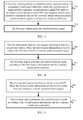
- FIG. 3 shows a schematic flowchart of a method 200 for transmitting a common signal according to another embodiment of the present invention.
- the method may be executed by a first base station.
- the method 200 is used to send a synchronization signal to user equipment UE in a first cell that belongs to the first base station, the first cell includes at least two nodes, and the at least two nodes include a first node and at least one second node.
- the method 200 includes:
- the first base station may use a UE-specific sequence initialization identifier to generate a sequence of the synchronization signal.
- the first base station may use a numerical value X1 as a sequence initialization identifier for generating a sequence corresponding to a PSS of the first node, and use a numerical value X2 as a sequence initialization identifier for generating a sequence corresponding to an SSS of the first node, where X1 and X2 depend on a user identifier or a device identifier of the first UE, or X1 and X2 are any integers from 0 to 503.
- this embodiment of the present invention is not limited thereto.
- the first base station may generate and send a synchronization signal of a node according to only one sequence initialization identifier, and the node may be any node of the first node and the at least one second node.
- the first base station may separately generate and send synchronization signals of multiple nodes according to multiple sequence initialization identifiers, where the multiple nodes may be any nodes of the first node and the at least one second node, and a synchronization signal of each node in the multiple nodes may include only a PSS, may include only an SSS, or may include both a PSS and an SSS.
- the sequence initialization identifiers separately used by the first base station when generating the synchronization signals of the multiple nodes may be different from each other, that is, sequence initialization identifiers used for generating synchronization signals of any two nodes in the multiple nodes are different.
- the first base station may use a same sequence initialization identifier for synchronization signals of some nodes and use different sequence initialization identifiers for synchronization signals of rest nodes.
- this embodiment of the present invention is not limited thereto.
- sequence initialization identifiers separately used by the first base station when generating synchronization signals of the at least two nodes are different includes:
- the first base station may further notify the first UE of a cell identity of the first cell, so that the first UE performs further measurement on the cell according to the cell identity.
- the method 200 further includes:
- the first base station may further send the cell identity to the first UE in a cross-carrier or cross-cell manner, for example, the first base station sends a synchronization signal of a secondary serving cell of the first UE, and the first base station sends the cell identity by using a primary serving cell of the first UE.
- the primary serving cell and the secondary serving cell of the first UE may use different carrier types.
- this embodiment of the present invention is not limited thereto.
- the first base station may further notify the first UE of the sequence initialization identifier used when generating the synchronization signal, so that the first UE can detect the synchronization signal according to the sequence initialization identifier, thereby avoiding that the first UE performs blind detection, and reducing complexity of the first UE.
- the method 200 further includes:
- the first base station may send the sequence initialization identifier to the first UE in multiple manners.
- the first base station may send physical layer signaling to the first UE, for example, a PDCCH or an ePDCCH, where the physical layer signaling is used to indicate the sequence initialization identifier of the synchronization signal.
- the first base station may send higher layer signaling to the first UE, for example, RRC signaling, where the higher layer signaling is used to indicate the sequence initialization identifier of the synchronization signal.
- the first base station may send at least two sequence initialization identifiers to the first UE by using higher layer signaling, and instruct, by using physical layer signaling, the first UE to use which one or which sequence initialization identifiers in the at least two sequence initialization identifiers to receive the synchronization signal.
- the physical layer signaling or the higher layer signaling may be broadcast signaling or UE-specific signaling.
- this embodiment of the present invention is not limited thereto.
- each node of the first node and the at least one second node may continuously send the synchronization signal in a relatively large time scale, or may send the synchronization signal in a triggering mode according to UE-related time. Specifically, it may be determined that a sending condition of the synchronization signal is met, and the synchronization signal is generated according to the sequence initialization identifier and sent.
- a triggering condition of the synchronization signal refer to the triggering condition in the foregoing embodiment.
- this embodiment of the present invention is not limited thereto.
- that the first base station generates the synchronization signal according to a sequence initialization identifier includes:
- the method 200 further includes:
- that the first base station generates the synchronization signal according to a sequence initialization identifier includes:
- the one or more nodes may use preset configuration information to send the synchronization signal, or may determine to-be-used configuration information according to a current status and notify the first UE of the configuration information, so that the first UE receives the synchronization signal according to the configuration information and the sequence initialization identifier.
- the method 200 further includes:
- the configuration information of the synchronization signal includes at least one of the following information: sending time information of the synchronization signal, information about sending times of the synchronization signal, sending interval information of the synchronization signal, type information of a carrier carrying the synchronization signal, identification information of the synchronization signal, transmit power information of the synchronization signal, antenna port information of the synchronization signal, and pattern information of a resource element RE occupied by the synchronization signal.
- a synchronization signal is unbound from a cell identity, so that multiple nodes in a cell can send different synchronization signals to user equipment, and the user equipment can further distinguish between different nodes according to the synchronization signals and separately establish synchronization with the different nodes, thereby improving communications efficiency and user experience.
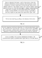
- FIG. 7 shows a schematic flowchart of a method 300 for transmitting a common signal according to still another embodiment of the present invention.
- the method 300 may be executed by user equipment UE, and as shown in FIG. 7 , the method 300 includes:
- the common signal includes at least one of the following signals: a primary synchronization signal PSS, a secondary synchronization signal SSS, a physical broadcast channel PBCH, a cell-specific reference signal CRS, a discovery signal DS, and system information block type 1 SIB1.
- the UE may determine the first configuration of the common signal according to a preset condition, or may determine the first configuration of the common signal by receiving indication information sent by the first base station.
- this embodiment of the present invention is not limited thereto.
- S310 that determine a first configuration of a common signal includes:
- the UE when the UE sends, to the first base station, first request information used to request the first base station to send the common signal, and configuration information that the first base station sends the common signal according to the first request information is preset on the UE and on the first base station side, the UE may determine the first configuration according to the preset condition.
- the UE may request, in the first request information, configuration information used to send the common signal, and determine the first configuration according to the first request information.
- the UE may determine the first configuration by receiving the indication information that is sent by the first base station and used to indicate the first configuration.
- the UE may further determine the first configuration by receiving indication information that is sent by the first base station by using the second base station and used to indicate the first configuration.
- this embodiment of the present invention is not limited thereto.
- S310 that determine a first configuration of a common signal includes:
- the UE may receive physical layer signaling sent by the first base station, for example, a PDCCH or an ePDCCH, where the physical layer signaling carries the first configuration information.
- the UE may receive higher layer signaling sent by the first base station, for example, RRC signaling, where the higher layer signaling carries the first configuration information.
- the UE may receive higher layer signaling sent by the first base station and receive physical layer signaling sent by the first base station, where the higher layer signaling indicates at least one set of configuration information of the common signal, and the physical layer signaling is used to instruct the UE to use which set of configuration information in the at least one set of configuration information to receive the common signal.
- the physical layer signaling or the higher layer signaling may be broadcast signaling or UE-specific signaling. However, this embodiment of the present invention is not limited thereto.
- the sending condition of the common signal includes at least one of the following conditions:
- the second UE may be the UE or may be another UE except the UE.
- this embodiment of the present invention is not limited thereto.
- the first configuration includes at least one of the following information: information about a time-frequency resource used during sending of the common signal, information about a code resource used during the sending of the common signal, identification information of the common signal, information about an antenna port corresponding to the common signal, and information about power used during the sending of the common signal.
- the information about the time-frequency resource used during the sending of the common signal includes at least one of the following information: sending time information of the common signal, information about sending times of the common signal, sending interval information of the common signal, type information of a carrier carrying the common signal, frequency information of the carrier carrying the common signal, information about a physical resource block PRB carrying the common signal, and pattern information of a resource element RE occupied by the common signal; and the information about the code resource used during the sending of the common signal includes scrambling code information of the common signal.
- the method 300 further includes:
- the method 300 further includes:
- the method 300 further includes:
- a base station sends a common signal in a triggering mode, so that the common signal is sent more flexibly, thereby reducing an overhead during sending of the common signal, reducing a possibility of interference caused by the sending of the common signal to a neighboring cell, and improving user experience.
- FIG. 8 shows a schematic flowchart of a method 400 for transmitting a common signal according to still another embodiment of the present invention.
- the method may be executed by a UE, and as shown in FIG. 8 , the method 400 includes:
- a base station sends a common signal in a triggering mode, so that the common signal is sent more flexibly, thereby reducing an overhead during sending of the common signal, reducing a possibility of interference caused by the sending of the common signal to a neighboring cell, and improving user experience.
- FIG. 9 shows a schematic flowchart of a method 500 for transmitting a common signal according to still another embodiment of the present invention.
- the method may be executed by a UE that is used to receive a synchronization signal sent by a first cell by using a first base station to which the first cell belongs, the first cell includes at least two nodes, and the at least two nodes include a first node and at least one second node.
- the method 500 includes:
- a synchronization signal is unbound from a cell identity, so that multiple nodes in a cell can send different synchronization signals to user equipment, and the user equipment can further distinguish between different nodes according to the synchronization signals and separately establish synchronization with the different nodes, thereby improving communications efficiency and user experience.
- the UE may acquire a sequence initialization identifier used for a synchronization signal of a node of the first node and the at least one second node, and receive the synchronization signal according to the sequence initialization identifier.
- the UE may acquire sequence initialization identifiers used for synchronization signals of multiple nodes of the first node and the at least one second node, and receive the corresponding synchronization signals according to the sequence initialization identifiers.
- this embodiment of the present invention is not limited thereto.
- the synchronization signal of the at least one second node has the same sequence initialization identifier, and the sequence initialization identifier of the synchronization signal of the first node is different from the sequence initialization identifier of the synchronization signal of the at least one second node; or the sequence initialization identifiers of the synchronization signals of the at least two nodes are different from each other.
- the UE may acquire the sequence initialization identifier of the synchronization signal according to a preset condition, or the UE may directly receive the sequence initialization identifier that is of the synchronization signal and sent by the first base station; when a serving base station of the UE is a second base station, the UE may further receive the sequence initialization identifier that is of the synchronization signal and sent by the first base station by using the second base station.
- S510 that acquire a sequence initialization identifier of a synchronization signal includes:
- the sequence initialization identifier of the synchronization signal of the first node is the cell identity of the first cell.
- the sending condition of the synchronization signal includes at least one of the following conditions:
- the method 500 includes:
- the method 500 further includes:
- S520a that detect, according to the sequence initialization identifier of the synchronization signal, the synchronization signal sent by the first base station according to the request information includes:
- the configuration information of the synchronization signal includes at least one of the following information: sending time information of the synchronization signal, information about sending times of the synchronization signal, sending interval information of the synchronization signal, type information of a carrier carrying the synchronization signal, identification information of the synchronization signal, transmit power information of the synchronization signal, antenna port information of the synchronization signal, and pattern information of a resource element RE occupied by the synchronization signal.
- a synchronization signal is unbound from a cell identity, so that multiple nodes in a cell can send different synchronization signals to user equipment, and the user equipment can further distinguish between different nodes according to the synchronization signals and separately establish synchronization with the different nodes, thereby improving communications efficiency and user experience.
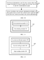
- FIG. 11 shows a schematic block diagram of a base station 600 according to an embodiment of the present invention.
- the base station 600 includes:
- the base station in this embodiment of the present invention sends a common signal in a triggering mode, so that the common signal is sent more flexibly, thereby reducing an overhead during sending of the common signal, reducing a possibility of interference caused by the sending of the common signal to a neighboring cell, and improving user experience.
- the common signal includes at least one of the following signals: a primary synchronization signal PSS, a secondary synchronization signal SSS, a physical broadcast channel PBCH, a cell-specific reference signal CRS, a discovery signal DS, and system information block type 1 SIB1.
- the base station 600 further includes:
- the base station 600 further includes:
- the base station 600 further includes:
- the first configuration includes at least one of the following information: information about a time-frequency resource used during sending of the common signal, information about a code resource used during the sending of the common signal, identification information of the common signal, information about an antenna port corresponding to the common signal, and information about power used during the sending of the common signal.
- the base station 600 further includes:
- the sending module 720 is further configured to send indication information to first user equipment UE, where the indication information is used to indicate a cell identity of the first cell.
- the first node is a node that continuously sends the synchronization signal, so that the first UE first establishes synchronization with the first node in the first cell.
- the base station 700 further includes:
- the configuration information of the synchronization signal includes at least one of the following information: sending time information of the synchronization signal, information about sending times of the synchronization signal, sending interval information of the synchronization signal, type information of a carrier carrying the synchronization signal, identification information of the synchronization signal, transmit power information of the synchronization signal, antenna port information of the synchronization signal, and pattern information of a resource element RE occupied by the synchronization signal.
- the base station in this embodiment of the present invention unbinds a synchronization signal from a cell identity, so that multiple nodes in a cell can send different synchronization signals to user equipment, and the user equipment can further distinguish between different nodes according to the synchronization signals and separately establish synchronization with the different nodes, thereby improving communications efficiency and user experience.
- FIG. 16 shows a schematic block diagram of user equipment UE 800 according to an embodiment of the present invention.
- the UE 800 includes:
- the common signal includes at least one of the following signals: a primary synchronization signal PSS, a secondary synchronization signal SSS, a physical broadcast channel PBCH, a cell-specific reference signal CRS, a discovery signal DS, and system information block type 1 SIB1.
- the first configuration includes at least one of the following information: information about a time-frequency resource used during sending of the common signal, information about a code resource used during the sending of the common signal, identification information of the common signal, information about an antenna port corresponding to the common signal, and information about power used during the sending of the common signal.
- the UE 800 further includes:
- the user equipment 900 may be corresponding to a third user equipment in a method for transmitting a common signal according to an embodiment of the present invention, and the foregoing and other operations and/or functions of modules in the user equipment 900 are separately intended to implement a corresponding process of the method in FIG. 8 ; for brevity, details are not described herein again.
- the detecting module 1020 is specifically configured to detect, according to the sequence initialization identifier of the synchronization signal, the synchronization signal that is sent by the first base station when a sending condition of the common signal is met.
- the UE 1000 further includes:
- the user equipment 1000 may be corresponding to user equipment in a method for transmitting a common signal according to an embodiment of the present invention, and the foregoing and other operations and/or functions of modules in the user equipment 1000 are separately intended to implement corresponding processes of methods in FIG. 9 and FIG. 10 ; for brevity, details are not described herein again.
- the base station in this embodiment of the present invention sends a common signal in a triggering mode, so that the common signal is sent more flexibly, thereby reducing an overhead during sending of the common signal, reducing a possibility of interference caused by the sending of the common signal to a neighboring cell, and improving user experience.
- the processor 1110 may be a central processing unit (Central Processing Unit, "CPU” for short), or the processor 1110 may further be another general-purpose processor, a digital signal processor (DSP), an application-specific integrated circuit (ASIC), a field programmable gate array (FPGA), another programmable logic device, a discrete gate or transistor logic device, a discrete hardware component, or the like.
- the general-purpose processor may be a microprocessor or the processor may also be any conventional processor, or the like.
- the memory 1120 may include a read-only memory and a random access memory, and provides an instruction and data to the processor 1110.
- a part of the memory 1120 may further include a nonvolatile random access memory.
- the memory 1120 may further store information about a device type.
- the steps in the foregoing methods may be completed by means of an integrated logic circuit of hardware in the processor 1110 or an instruction in a form of software. Steps of the methods disclosed with reference to the embodiments of the present invention may be directly executed and completed by a hardware processor, or may be executed and completed by using a combination of hardware and software modules in the processor.
- the software module may be located in a mature storage medium in the field, such as a random access memory, a flash memory, a read-only memory, a programmable read-only memory, an electrically-erasable programmable memory, or a register.
- the storage medium is located in the memory 1120.
- the processor 1110 reads information from the memory 1120, and completes the steps of the foregoing methods in combination with the hardware of the processor 1110. To avoid repetition, details are not described herein again.
- the processor 1110 is further configured to, before the first configuration used to send the common signal is determined, determine that a sending condition of the common signal is met.
- the sender 1140 is further configured to, before the common signal is sent according to the first configuration, send first configuration information of the common signal to a second base station, where the first configuration information is used to indicate the first configuration; and/or the sender 1140 is further configured to, before the common signal is sent according to the first configuration, send first configuration information of the common signal to user equipment UE, where the first configuration information is used to indicate the first configuration.
- the sending condition of the common signal includes at least one of the following conditions:
- the information about the time-frequency resource used during the sending of the common signal includes at least one of the following information: sending time information of the common signal, information about sending times of the common signal, sending interval information of the common signal, type information of a carrier carrying the common signal, frequency information of the carrier carrying the common signal, information about a physical resource block PRB carrying the common signal, and pattern information of a resource element RE occupied by the common signal; and the information about the code resource used during the sending of the common signal includes scrambling code information of the common signal.
- the processor 1110 is further configured to perform rate matching on at least one first signal, except the common signal, in to-be-sent signals according to the time-frequency resource information of the common signal.
- the sender 1140 is further configured to send second configuration information to a third UE, where the second configuration information is used to indicate the time-frequency resource information, so that the third UE performs rate matching according to the second configuration information.
- the first configuration is preset on the first base station; or the processor 1110 is specifically configured to select the first configuration from multiple preset configurations.
- the sender 1140 is further configured to, send any other signal or data except the common signal on a time-frequency resource that is reserved for transmitting the common signal but is actually not used to transmit the common signal.
- the base station 1100 may be corresponding to a first base station in a method for transmitting a common signal according to an embodiment of the present invention, and the foregoing and other operations and/or functions of modules in the base station 1100 are separately intended to implement corresponding processes of methods in FIG. 1 and FIG. 2 ; for brevity, details are not described herein again.
- FIG. 22 shows a schematic block diagram of a base station 1200 according to still another embodiment of the present invention, where the base station 1200 is used to send a synchronization signal to user equipment UE in a first cell that belongs to the base station 1200, the first cell includes at least two nodes, and the at least two nodes include a first node and at least one second node.
- the base station 1200 includes: a processor 1210, a memory 1220, a bus system 1230, and a sender 1240.
- the processor 1210, the memory 1220, and the sender 1240 are connected to each other by using the bus system 630, where the memory 1220 is configured to store an instruction, and the processor 1210 invokes, by using the bus system 1230, the instruction stored in the memory 1220.
- the processor 1210 is configured to generate the synchronization signal according to a sequence initialization identifier, where the synchronization signal includes a primary synchronization signal PSS and/or a secondary synchronization signal SSS, sequence initialization identifiers separately used by the generating module when generating synchronization signals of the at least two nodes are different, and the first cell belongs to the base station; and the sender 1240 is configured to send the synchronization signal generated by the processor 1210.
- the base station in this embodiment of the present invention unbinds a synchronization signal from a cell identity, so that multiple nodes in a cell can send different synchronization signals to user equipment, and the user equipment can further distinguish between different nodes according to the synchronization signals and separately establish synchronization with the different nodes, thereby improving communications efficiency and user experience.
- the processor 1210 may be a central processing unit (Central Processing Unit, "CPU” for short), or the processor 1210 may further be another general-purpose processor, a digital signal processor (DSP), an application-specific integrated circuit (ASIC), a field programmable gate array (FPGA), another programmable logic device, a discrete gate or transistor logic device, a discrete hardware component, or the like.
- the general-purpose processor may be a microprocessor or the processor may also be any conventional processor, or the like.
- the memory 1220 may include a read-only memory and a random access memory, and provides an instruction and data to the processor 1210.
- a part of the memory 1220 may further include a nonvolatile random access memory.
- the memory 1220 may further store information about a device type.
- the bus system 1230 may include a power bus, a control bus, a status signal bus, and the like. However, for clarity of description, various buses are marked as the bus system 1230 in the figure.
- the steps in the foregoing methods may be completed by means of an integrated logic circuit of hardware in the processor 1210 or an instruction in a form of software. Steps of the methods disclosed with reference to the embodiments of the present invention may be directly executed and completed by a hardware processor, or may be executed and completed by using a combination of hardware and software modules in the processor.
- the software module may be located in a mature storage medium in the field, such as a random access memory, a flash memory, a read-only memory, a programmable read-only memory, an electrically-erasable programmable memory, or a register.
- the storage medium is located in the memory 1220.
- the processor 1210 reads information from the memory 1220, and completes the steps of the foregoing methods in combination with the hardware of the processor 1210. To avoid repetition, details are not described herein again.
- the same sequence initialization identifier is used by the processor 1210 when generating the synchronization signal of the at least one second node, and the sequence initialization identifier used by the processor 1210 when generating the synchronization signal of the first node is different from the sequence initialization identifier separately used by the first base station when generating the synchronization signal of the at least one second node; or the sequence initialization identifiers separately used by the processor 1210 when generating the synchronization signals of the at least two nodes are different from each other.
- the sender 1240 is further configured to send indication information to first user equipment UE, where the indication information is used to indicate a cell identity of the first cell.
- the sender 1240 is further configured to, before the synchronization signal is sent, send, to the first UE, the sequence initialization identifier used by the first base station when generating the synchronization signal.
- the sequence initialization identifier used by the processor 1210 when generating the synchronization signal of the first node is the cell identity of the first cell.
- the first node is a node that continuously sends the synchronization signal, so that the first UE first establishes synchronization with the first node in the first cell.
- the base station 1200 further includes:
- the base station 1200 further includes:
- the base station 1200 further includes:
- the sender 1240 is further configured to, before the synchronization signal is sent, send configuration information of the synchronization signal to the first UE, where the configuration information is used by the first UE to detect the synchronization signal.
- the configuration information of the synchronization signal includes at least one of the following information: sending time information of the synchronization signal, information about sending times of the synchronization signal, sending interval information of the synchronization signal, type information of a carrier carrying the synchronization signal, identification information of the synchronization signal, transmit power information of the synchronization signal, antenna port information of the synchronization signal, and pattern information of a resource element RE occupied by the synchronization signal.
- the base station 1200 may be corresponding to a first base station in a method for transmitting a common signal according to an embodiment of the present invention, and the foregoing and other operations and/or functions of modules in the base station 1200 are separately intended to implement corresponding processes of methods in FIG. 3 to FIG. 6 ; for brevity, details are not described herein again.
- the base station in this embodiment of the present invention unbinds a synchronization signal from a cell identity, so that multiple nodes in a cell can send different synchronization signals to user equipment, and the user equipment can further distinguish between different nodes according to the synchronization signals and separately establish synchronization with the different nodes, thereby improving communications efficiency and user experience.
- FIG. 23 shows a schematic block diagram of user equipment UE 1300 according to an embodiment of the present invention.
- the UE 1300 includes: a processor 1310, a memory 1320, a bus system 1330, and a receiver 1340.
- the processor 1310, the memory 1320, and the receiver 1340 are connected to each other by using the bus system 1330, where the memory 1320 is configured to store an instruction, and the processor 1310 invokes, by using the bus system 1330, the instruction stored in the memory 1320.
- the processor 1310 is configured to determine a first configuration of a common signal; and the receiver 1340 is configured to receive, according to the first configuration that is of the common signal and determined by the processor 1310, the common signal that is sent by the first base station when a sending condition of the common signal is met.
- a base station sends a common signal in a triggering mode, so that the common signal is sent more flexibly, thereby reducing an overhead during sending of the common signal, reducing a possibility of interference caused by the sending of the common signal to a neighboring cell, and improving user experience.
- the processor 1310 may be a central processing unit (Central Processing Unit, "CPU” for short), or the processor 1310 may further be another general-purpose processor, a digital signal processor (DSP), an application-specific integrated circuit (ASIC), a field programmable gate array (FPGA), another programmable logic device, a discrete gate or transistor logic device, a discrete hardware component, or the like.
- the general-purpose processor may be a microprocessor or the processor may also be any conventional processor, or the like.
- the memory 1320 may include a read-only memory and a random access memory, and provides an instruction and data to the processor 1310.
- a part of the memory 1320 may further include a nonvolatile random access memory.
- the memory 1320 may further store information about a device type.
- the bus system 1330 may include a power bus, a control bus, a status signal bus, and the like. However, for clarity of description, various buses are marked as the bus system 1330 in the figure.
- the steps in the foregoing methods may be completed by means of an integrated logic circuit of hardware in the processor 1310 or an instruction in a form of software. Steps of the methods disclosed with reference to the embodiments of the present invention may be directly executed and completed by a hardware processor, or may be executed and completed by using a combination of hardware and software modules in the processor.
- the software module may be located in a mature storage medium in the field, such as a random access memory, a flash memory, a read-only memory, a programmable read-only memory, an electrically-erasable programmable memory, or a register.
- the storage medium is located in the memory 1320.
- the processor 1310 reads information from the memory 1320, and completes the steps of the foregoing methods in combination with the hardware of the processor 1310. To avoid repetition, details are not described herein again.
- the common signal includes at least one of the following signals: a primary synchronization signal PSS, a secondary synchronization signal SSS, a physical broadcast channel PBCH, a cell-specific reference signal CRS, a discovery signal DS, and system information block type 1 SIB1.
- the processor 1310 specifically determines the first configuration by using first configuration information received by the receiver 1340, where the first configuration information is used to indicate the first configuration.
- the sending condition of the common signal includes at least one of the following conditions:
- the first configuration includes at least one of the following information: information about a time-frequency resource used during sending of the common signal, information about a code resource used during the sending of the common signal, identification information of the common signal, information about an antenna port corresponding to the common signal, and information about power used during the sending of the common signal.
- the information about the time-frequency resource used during the sending of the common signal includes at least one of the following information: sending time information of the common signal, information about sending times of the common signal, sending interval information of the common signal, type information of a carrier carrying the common signal, frequency information of the carrier carrying the common signal, information about a physical resource block PRB carrying the common signal, and pattern information of a resource element RE occupied by the common signal; and the information about the code resource used during the sending of the common signal includes scrambling code information of the common signal.
- the processor 1310 is further configured to perform rate matching on at least one first signal, except the common signal, in to-be-sent signals of the first base station according to the time-frequency resource information of the common signal.
- the user equipment 1300 may be corresponding to user equipment in a method for transmitting a common signal according to an embodiment of the present invention, and the foregoing and other operations and/or functions of modules in the user equipment 1300 are separately intended to implement a corresponding process of the method in FIG. 7 ; for brevity, details are not described herein again.
- FIG. 24 shows a schematic block diagram of user equipment UE 1400 according to an embodiment of the present invention.
- the UE 1400 includes: a processor 1410, a memory 1420, a bus system 1430, and a receiver 1440.
- the processor 1410 and the memory 1420 are connected to each other by using the bus system 1430, where the memory 1420 is configured to store an instruction, and the processor 1410 invokes, by using the bus system 1430, the instruction stored in the memory 1420.
- the receiver 1440 is configured to receive indication information sent by a base station, where the indication information is used to indicate a time-frequency resource occupied by a common signal that is transmitted non-periodically, and the common signal includes at least one of the following signals: a primary synchronization signal PSS, a secondary synchronization signal SSS, a physical broadcast channel PBCH, a cell-specific reference signal CRS, a discovery signal DS, and system information block type 1 SIB1; and the processor 1410 is configured to perform rate matching according to the indication information received by the receiver 1440.
- the indication information is used to indicate a time-frequency resource occupied by a common signal that is transmitted non-periodically
- the common signal includes at least one of the following signals: a primary synchronization signal PSS, a secondary synchronization signal SSS, a physical broadcast channel PBCH, a cell-specific reference signal CRS, a discovery signal DS, and system information block type 1 SIB1; and the processor 1410 is configured to perform rate matching according to
- the processor 1410 may be a central processing unit (Central Processing Unit, "CPU” for short), or the processor 1410 may further be another general-purpose processor, a digital signal processor (DSP), an application-specific integrated circuit (ASIC), a field programmable gate array (FPGA), another programmable logic device, a discrete gate or transistor logic device, a discrete hardware component, or the like.
- the general-purpose processor may be a microprocessor or the processor may also be any conventional processor, or the like.
- the memory 1420 may include a read-only memory and a random access memory, and provides an instruction and data to the processor 1410.
- a part of the memory 1420 may further include a nonvolatile random access memory.
- the memory 1420 may further store information about a device type.
- the bus system 1430 may include a power bus, a control bus, a status signal bus, and the like. However, for clarity of description, various buses are marked as the bus system 1430 in the figure.
- the steps in the foregoing methods may be completed by means of an integrated logic circuit of hardware in the processor 1410 or an instruction in a form of software. Steps of the methods disclosed with reference to the embodiments of the present invention may be directly executed and completed by a hardware processor, or may be executed and completed by using a combination of hardware and software modules in the processor.
- the software module may be located in a mature storage medium in the field, such as a random access memory, a flash memory, a read-only memory, a programmable read-only memory, an electrically-erasable programmable memory, or a register.
- the storage medium is located in the memory 1420.
- the processor 1410 reads information from the memory 1420, and completes the steps of the foregoing methods in combination with the hardware of the processor 1410. To avoid repetition, details are not described herein again.
- the user equipment 1400 may be corresponding to a fourth user equipment in a method for transmitting a common signal according to an embodiment of the present invention, and the foregoing and other operations and/or functions of modules in the user equipment 1400 are separately intended to implement a corresponding process of the method in FIG. 8 ; for brevity, details are not described herein again.
- a base station sends a common signal in a triggering mode, so that the common signal is sent more flexibly, thereby reducing an overhead during sending of the common signal, reducing a possibility of interference caused by the sending of the common signal to a neighboring cell, and improving user experience.
- FIG. 25 shows a schematic block diagram of user equipment UE 1500 according to an embodiment of the present invention, where the user equipment 1500 is used to receive a synchronization signal sent by a first cell by using a first base station to which the first cell belongs, the first cell includes at least two nodes, and the at least two nodes include a first node and at least one second node.
- the UE 1500 includes: a processor 1510, a memory 1520, and a bus system 1530.
- the processor 1510 and the memory 1520 are connected to each other by using the bus system 1530, where the memory 1520 is configured to store an instruction, and the processor 1510 invokes, by using the bus system 1530, the instruction stored in the memory 1520, so as to: acquire a sequence initialization identifier of a synchronization signal, where the synchronization signal includes a primary synchronization signal PSS and/or a secondary synchronization signal SSS, and sequence initialization identifiers of synchronization signals of the at least two nodes are different; and detect, according to the sequence initialization identifier of the synchronization signal, the synchronization signal sent by the first base station.
- the memory 1520 is configured to store an instruction
- the processor 1510 invokes, by using the bus system 1530, the instruction stored in the memory 1520, so as to: acquire a sequence initialization identifier of a synchronization signal, where the synchronization signal includes a primary synchronization signal PSS and/or a secondary synchronization signal SSS, and sequence initial
- a synchronization signal is unbound from a cell identity, so that multiple nodes in a cell can send different synchronization signals to the user equipment, and the user equipment can further distinguish between different nodes according to the synchronization signals and separately establish synchronization with the different nodes, thereby improving communications efficiency and user experience.
- the processor 1510 may be a central processing unit (Central Processing Unit, "CPU” for short), or the processor 1510 may further be another general-purpose processor, a digital signal processor (DSP), an application-specific integrated circuit (ASIC), a field programmable gate array (FPGA), another programmable logic device, a discrete gate or transistor logic device, a discrete hardware component, or the like.
- the general-purpose processor may be a microprocessor or the processor may also be any conventional processor, or the like.
- the memory 1520 may include a read-only memory and a random access memory, and provides an instruction and data to the processor 1510.
- a part of the memory 1520 may further include a nonvolatile random access memory.
- the memory 1520 may further store information about a device type.
- the steps in the foregoing methods may be completed by means of an integrated logic circuit of hardware in the processor 1510 or an instruction in a form of software. Steps of the methods disclosed with reference to the embodiments of the present invention may be directly executed and completed by a hardware processor, or may be executed and completed by using a combination of hardware and software modules in the processor.
- the software module may be located in a mature storage medium in the field, such as a random access memory, a flash memory, a read-only memory, a programmable read-only memory, an electrically-erasable programmable memory, or a register.
- the storage medium is located in the memory 1520.
- the processor 1510 reads information from the memory 1520, and completes the steps of the foregoing methods in combination with the hardware of the processor 1510. To avoid repetition, details are not described herein again.
- the receiver 1540 is further configured to receive indication information sent by the first base station, where the indication information is used to indicate a cell identity of the first cell.
- the processor 1510 is specifically configured to acquire the sequence initialization identifier by using the receiver 1540 to receive the sequence initialization identifier that is of the synchronization signal and sent by first base station.
- the processor 1510 is specifically configured to detect, according to the sequence initialization identifier of the synchronization signal, the synchronization signal that is sent by the first base station when a sending condition of the common signal is met.
- the configuration information of the synchronization signal includes at least one of the following information: sending time information of the synchronization signal, information about sending times of the synchronization signal, sending interval information of the synchronization signal, type information of a carrier carrying the synchronization signal, identification information of the synchronization signal, transmit power information of the synchronization signal, antenna port information of the synchronization signal, and pattern information of a resource element RE occupied by the synchronization signal.
- the units described as separate parts may or may not be physically separate, and parts displayed as units may or may not be physical units, may be located in one position, or may be distributed on a plurality of network units. Some or all of the units may be selected according to actual needs to achieve the objectives of the solutions of the embodiments of the present invention.
Landscapes
- Engineering & Computer Science (AREA)
- Signal Processing (AREA)
- Computer Networks & Wireless Communication (AREA)
- Mobile Radio Communication Systems (AREA)
Priority Applications (1)
| Application Number | Priority Date | Filing Date | Title |
|---|---|---|---|
| EP19162442.8A EP3592053B1 (fr) | 2013-04-07 | 2013-04-07 | Procédé de transmission de signal commun et appareil correspondant |
Applications Claiming Priority (1)
| Application Number | Priority Date | Filing Date | Title |
|---|---|---|---|
| PCT/CN2013/073822 WO2014166032A1 (fr) | 2013-04-07 | 2013-04-07 | Procédé et appareil d'émission d'un signal commun |
Related Child Applications (2)
| Application Number | Title | Priority Date | Filing Date |
|---|---|---|---|
| EP19162442.8A Division EP3592053B1 (fr) | 2013-04-07 | 2013-04-07 | Procédé de transmission de signal commun et appareil correspondant |
| EP19162442.8A Division-Into EP3592053B1 (fr) | 2013-04-07 | 2013-04-07 | Procédé de transmission de signal commun et appareil correspondant |
Publications (3)
| Publication Number | Publication Date |
|---|---|
| EP2941066A1 true EP2941066A1 (fr) | 2015-11-04 |
| EP2941066A4 EP2941066A4 (fr) | 2016-01-06 |
| EP2941066B1 EP2941066B1 (fr) | 2019-06-12 |
Family
ID=51688814
Family Applications (2)
| Application Number | Title | Priority Date | Filing Date |
|---|---|---|---|
| EP19162442.8A Active EP3592053B1 (fr) | 2013-04-07 | 2013-04-07 | Procédé de transmission de signal commun et appareil correspondant |
| EP13881732.5A Active EP2941066B1 (fr) | 2013-04-07 | 2013-04-07 | Procédé et appareil d'émission d'un signal commun |
Family Applications Before (1)
| Application Number | Title | Priority Date | Filing Date |
|---|---|---|---|
| EP19162442.8A Active EP3592053B1 (fr) | 2013-04-07 | 2013-04-07 | Procédé de transmission de signal commun et appareil correspondant |
Country Status (4)
| Country | Link |
|---|---|
| US (1) | US12294960B2 (fr) |
| EP (2) | EP3592053B1 (fr) |
| CN (2) | CN104285483B (fr) |
| WO (1) | WO2014166032A1 (fr) |
Cited By (6)
| Publication number | Priority date | Publication date | Assignee | Title |
|---|---|---|---|---|
| WO2019125750A1 (fr) * | 2017-12-18 | 2019-06-27 | Kyocera Corporation | Synchronisation de liaison descendante avancée pour une acquisition de signal de synchronisation commune |
| WO2019125749A1 (fr) * | 2017-12-18 | 2019-06-27 | Kyocera Corporation | Temps d'acquisition de système réduit pour mtc utilisant un canal de synchronisation commun |
| EP3547617A4 (fr) * | 2015-12-31 | 2019-10-30 | Huawei Technologies Co., Ltd. | Système ups modulaire et procédé de transmission de données pour dispositifs d'alimentation |
| US10803004B2 (en) | 2015-12-31 | 2020-10-13 | Huawei Technologies Co., Ltd. | Modular UPS system and data transmission method for power device |
| EP3823371A1 (fr) * | 2016-07-01 | 2021-05-19 | Guangdong Oppo Mobile Telecommunications Corp., Ltd. | Procédé et dispositif de détection de signal |
| EP4319355A3 (fr) * | 2016-06-30 | 2024-05-01 | NEC Corporation | Procédé et appareil de configuration de signal dans un système de communication sans fil |
Families Citing this family (18)
| Publication number | Priority date | Publication date | Assignee | Title |
|---|---|---|---|---|
| WO2017022776A1 (fr) * | 2015-08-05 | 2017-02-09 | シャープ株式会社 | Dispositif terminal, dispositif station de base et procédé de communication |
| CN107135533B (zh) * | 2016-02-26 | 2021-06-08 | 中兴通讯股份有限公司 | 一种信号传输方法、终端和网络侧设备 |
| KR20210024253A (ko) * | 2016-03-02 | 2021-03-04 | 텔레호낙티에볼라게트 엘엠 에릭슨(피유비엘) | 때때로 송신되는 미세 타이밍 기준 신호들로 동작하는 방법들 및 디바이스들 |
| CN107302424A (zh) * | 2016-04-15 | 2017-10-27 | 中兴通讯股份有限公司 | 一种系统信息的发送方法和装置 |
| CA3043782C (fr) * | 2016-05-26 | 2022-06-07 | Guangdong Oppo Mobile Telecommunications Corp., Ltd. | Procede de transmission de signal de reference, dispositif de reseau, et dispositif terminal |
| CN114286436B (zh) * | 2016-06-23 | 2023-06-23 | 中兴通讯股份有限公司 | 一种同步信号的发送方法、接收方法,通信节点 |
| AU2018263689B2 (en) * | 2017-05-05 | 2020-02-27 | Lg Electronics Inc. | Method for receiving synchronization signal, and device therefor |
| CN108988978B (zh) | 2017-06-01 | 2021-01-15 | 华为技术有限公司 | 扰码序列生成方法及装置 |
| EP3665796B1 (fr) * | 2017-08-10 | 2025-03-19 | ZTE Corporation | Communication de blocs de commande communs |
| CN109413591B (zh) * | 2017-08-11 | 2019-11-19 | 华为技术有限公司 | 一种数据传输方法、装置、系统、网络设备及用户设备 |
| US10972990B2 (en) * | 2017-09-11 | 2021-04-06 | Qualcomm Incorporated | System information rate matching |
| CN109688622B (zh) * | 2017-10-19 | 2022-02-18 | 中国移动通信有限公司研究院 | 一种信息传输方法、接收方法、网络设备及终端设备 |
| CN109803416B (zh) * | 2017-11-17 | 2024-10-15 | 华为技术有限公司 | 通信方法和通信设备 |
| CN112615704B (zh) * | 2018-08-10 | 2022-03-08 | 华为技术有限公司 | 一种同步信号的传输方法和装置 |
| EP4072202B1 (fr) | 2020-01-16 | 2023-12-27 | Huawei Technologies Co., Ltd. | Procédé et appareil pour transmettre un bloc d'informations de système, et support d'informations |
| US12375197B2 (en) * | 2023-12-18 | 2025-07-29 | Motorcomm (shanghai) Electronic Technology CO. LTD | Detection system for vehicle-mounted ethernet link synchronization signal |
| CN118075893A (zh) * | 2024-02-02 | 2024-05-24 | 中兴通讯股份有限公司 | 公共信号处理方法、装置及存储介质 |
| CN120166577A (zh) * | 2024-04-03 | 2025-06-17 | 中兴通讯股份有限公司 | 信令发送方法、接收方法、装置、存储介质及程序产品 |
Family Cites Families (21)
| Publication number | Priority date | Publication date | Assignee | Title |
|---|---|---|---|---|
| US6721562B2 (en) * | 2002-02-07 | 2004-04-13 | Motorola, Inc. | Method and apparatus for band class acquisition and assignment in a wireless communication system |
| US8982750B2 (en) * | 2009-01-16 | 2015-03-17 | Qualcomm Incorporated | Method and apparatus for transmitting overload indicator over the air |
| EP3402278A1 (fr) * | 2009-02-02 | 2018-11-14 | Mitsubishi Electric Corporation | Système de communication mobile, station de base et équipement utilisateur |
| US9154352B2 (en) * | 2009-04-21 | 2015-10-06 | Qualcomm Incorporated | Pre-communication for relay base stations in wireless communication |
| CN101958743B (zh) * | 2009-07-13 | 2014-12-10 | 中兴通讯股份有限公司 | 中继链路的同步信号映射方法及装置 |
| KR101253197B1 (ko) * | 2010-03-26 | 2013-04-10 | 엘지전자 주식회사 | 참조신호 수신 방법 및 사용자기기, 참조신호 전송 방법 및 기지국 |
| US20120113898A1 (en) * | 2010-11-09 | 2012-05-10 | Qualcomm Incorporated | Using precoding vector switching in uplink control channel |
| US8995400B2 (en) * | 2011-02-11 | 2015-03-31 | Qualcomm Incorporated | Method and apparatus for enabling channel and interference estimations in macro/RRH system |
| US9054842B2 (en) * | 2011-02-14 | 2015-06-09 | Qualcomm Incorporated | CRS (common reference signal) and CSI-RS (channel state information reference signal) transmission for remote radio heads (RRHs) |
| US9408168B2 (en) * | 2011-04-28 | 2016-08-02 | Lg Electronics Inc. | Method and apparatus for transmitting synchronization signal in carrier aggregation system |
| WO2012154004A2 (fr) * | 2011-05-12 | 2012-11-15 | 엘지전자 주식회사 | Procédé de transmission de signal au moyen d'une pluralité de ports d'antenne et appareil extrémité de transmission associé |
| CN102905370B (zh) * | 2011-07-26 | 2017-08-11 | 中兴通讯股份有限公司 | 一种实现控制信道资源配置的方法和系统 |
| US9629156B2 (en) * | 2011-08-12 | 2017-04-18 | Telefonaktiebolaget Lm Ericsson (Publ) | Aggregated carrier synchronization and reference signal transmitting and receiving methods, devices and systems |
| US20130229953A1 (en) * | 2011-08-16 | 2013-09-05 | Samsung Electronics Co., Ltd. | Apparatus and method for indicating synchronization signals in a wireless network |
| US9510212B2 (en) * | 2012-04-27 | 2016-11-29 | Qualcomm Incorporated | Signal designs for densely deployed network |
| US9253782B2 (en) * | 2012-05-11 | 2016-02-02 | Qualcomm Incorporated | Coexistence between LCTS and NCTS |
| US9014109B2 (en) * | 2012-06-05 | 2015-04-21 | Hitachi, Ltd. | Method and apparatus for bit-level PDSCH muting and/or receiver puncturing in LTE-advanced heterogeneous networks |
| KR101988506B1 (ko) * | 2012-12-14 | 2019-09-30 | 삼성전자 주식회사 | 무선 이동통신 시스템에서 디스커버리 신호를 송/수신하는 방법 및 장치 |
| US9060321B2 (en) * | 2013-02-26 | 2015-06-16 | Samsung Electronics Co., Ltd. | Methods and apparatus for demodulation reference signals and synchronization signals in extension carrier of LTE advanced |
| US8965391B1 (en) * | 2013-03-22 | 2015-02-24 | Sprint Spectrum L.P. | Methods, systems, and computer readable media for dynamic toggling of synchronization signaling to provide access control and free up resources |
| EP2963970B1 (fr) * | 2013-03-28 | 2022-01-05 | Huawei Technologies Co., Ltd. | Procédé et dispositif d'attribution de largeur de bande, équipement d'utilisateur et station de base |
-
2013
- 2013-04-07 CN CN201380024527.1A patent/CN104285483B/zh not_active Expired - Fee Related
- 2013-04-07 CN CN201810599132.9A patent/CN108683474B/zh active Active
- 2013-04-07 EP EP19162442.8A patent/EP3592053B1/fr active Active
- 2013-04-07 WO PCT/CN2013/073822 patent/WO2014166032A1/fr not_active Ceased
- 2013-04-07 EP EP13881732.5A patent/EP2941066B1/fr active Active
-
2015
- 2015-09-30 US US14/870,533 patent/US12294960B2/en active Active
Cited By (8)
| Publication number | Priority date | Publication date | Assignee | Title |
|---|---|---|---|---|
| EP3547617A4 (fr) * | 2015-12-31 | 2019-10-30 | Huawei Technologies Co., Ltd. | Système ups modulaire et procédé de transmission de données pour dispositifs d'alimentation |
| US10803004B2 (en) | 2015-12-31 | 2020-10-13 | Huawei Technologies Co., Ltd. | Modular UPS system and data transmission method for power device |
| EP4319355A3 (fr) * | 2016-06-30 | 2024-05-01 | NEC Corporation | Procédé et appareil de configuration de signal dans un système de communication sans fil |
| EP3823371A1 (fr) * | 2016-07-01 | 2021-05-19 | Guangdong Oppo Mobile Telecommunications Corp., Ltd. | Procédé et dispositif de détection de signal |
| US11153836B2 (en) | 2016-07-01 | 2021-10-19 | Guangdong Oppo Mobile Telecommunications Corp., Ltd. | Method and device for signal detection |
| US12207212B2 (en) | 2016-07-01 | 2025-01-21 | Guangdong Oppo Mobile Telecommunications Corp., Ltd. | Method and device for signal detection |
| WO2019125750A1 (fr) * | 2017-12-18 | 2019-06-27 | Kyocera Corporation | Synchronisation de liaison descendante avancée pour une acquisition de signal de synchronisation commune |
| WO2019125749A1 (fr) * | 2017-12-18 | 2019-06-27 | Kyocera Corporation | Temps d'acquisition de système réduit pour mtc utilisant un canal de synchronisation commun |
Also Published As
| Publication number | Publication date |
|---|---|
| EP3592053A1 (fr) | 2020-01-08 |
| WO2014166032A1 (fr) | 2014-10-16 |
| US20160021632A1 (en) | 2016-01-21 |
| CN108683474A (zh) | 2018-10-19 |
| US12294960B2 (en) | 2025-05-06 |
| EP3592053B1 (fr) | 2023-11-29 |
| CN108683474B (zh) | 2020-10-23 |
| CN104285483B (zh) | 2018-07-13 |
| EP2941066A4 (fr) | 2016-01-06 |
| EP2941066B1 (fr) | 2019-06-12 |
| CN104285483A (zh) | 2015-01-14 |
Similar Documents
| Publication | Publication Date | Title |
|---|---|---|
| EP2941066B1 (fr) | Procédé et appareil d'émission d'un signal commun | |
| EP3614737B1 (fr) | Procédé de mesure, procédé de configuration de mesure, et dispositif associé | |
| US11343800B2 (en) | Control channel resource indication method, user equipment, and network device | |
| EP3361805B1 (fr) | Procédé de traitement de canal de commande de liaison descendante physique amélioré, et équipement utilisateur | |
| US20210067258A1 (en) | Radio Resource Management Measurement Method and Apparatus | |
| EP3668205A1 (fr) | Procédé et appareil de localisation et de notification de mesure | |
| CN110972289B (zh) | 无线资源管理rrm测量的方法和装置 | |
| CN110463340B (zh) | 寻呼方法和寻呼装置 | |
| JP7342970B2 (ja) | Ssbに基づく測定方法及び装置 | |
| CN109417782B (zh) | 通信方法、通信装置、通信设备及计算机存储介质 | |
| CN116325605B (zh) | Tci状态列表更新方法、装置、设备及存储介质 | |
| EP3419331A1 (fr) | Procédé de transmission d'informations de système, station de base et terminal | |
| TWI756259B (zh) | 通訊方法、終端裝置和網路裝置 | |
| EP3448086A1 (fr) | Procédé de commutation de cellule, station de base et noeud de commande | |
| CN111277394A (zh) | 一种物理下行控制信道的传输方法、基站设备及用户设备 | |
| CN105101280A (zh) | 传输点识别和无线资源管理测量的方法、设备及系统 | |
| CN106165474B (zh) | 一种测量方法和设备 | |
| JP2020504942A (ja) | システム情報の伝送方法及び装置 | |
| CN109923888B (zh) | 通信方法、终端设备和网络设备 | |
| HK40002773A (en) | Communication method and communication apparatus | |
| HK40002423A (en) | Communications method, terminal device and network device | |
| HK40002423B (en) | Communications method, terminal device and network device | |
| HK40002773B (zh) | 通信方法、通信装置、通信设备及计算机存储介质 |
Legal Events
| Date | Code | Title | Description |
|---|---|---|---|
| PUAI | Public reference made under article 153(3) epc to a published international application that has entered the european phase |
Free format text: ORIGINAL CODE: 0009012 |
|
| 17P | Request for examination filed |
Effective date: 20150731 |
|
| AK | Designated contracting states |
Kind code of ref document: A1 Designated state(s): AL AT BE BG CH CY CZ DE DK EE ES FI FR GB GR HR HU IE IS IT LI LT LU LV MC MK MT NL NO PL PT RO RS SE SI SK SM TR |
|
| AX | Request for extension of the european patent |
Extension state: BA ME |
|
| A4 | Supplementary search report drawn up and despatched |
Effective date: 20151203 |
|
| RIC1 | Information provided on ipc code assigned before grant |
Ipc: H04L 5/00 20060101ALN20151127BHEP Ipc: H04W 56/00 20090101AFI20151127BHEP Ipc: H04J 11/00 20060101ALI20151127BHEP |
|
| DAX | Request for extension of the european patent (deleted) | ||
| STAA | Information on the status of an ep patent application or granted ep patent |
Free format text: STATUS: EXAMINATION IS IN PROGRESS |
|
| RIC1 | Information provided on ipc code assigned before grant |
Ipc: H04L 5/00 20060101ALI20170516BHEP Ipc: H04J 11/00 20060101ALI20170516BHEP Ipc: H04W 56/00 20090101AFI20170516BHEP |
|
| 17Q | First examination report despatched |
Effective date: 20170619 |
|
| GRAP | Despatch of communication of intention to grant a patent |
Free format text: ORIGINAL CODE: EPIDOSNIGR1 |
|
| STAA | Information on the status of an ep patent application or granted ep patent |
Free format text: STATUS: GRANT OF PATENT IS INTENDED |
|
| INTG | Intention to grant announced |
Effective date: 20181221 |
|
| GRAS | Grant fee paid |
Free format text: ORIGINAL CODE: EPIDOSNIGR3 |
|
| GRAA | (expected) grant |
Free format text: ORIGINAL CODE: 0009210 |
|
| STAA | Information on the status of an ep patent application or granted ep patent |
Free format text: STATUS: THE PATENT HAS BEEN GRANTED |
|
| AK | Designated contracting states |
Kind code of ref document: B1 Designated state(s): AL AT BE BG CH CY CZ DE DK EE ES FI FR GB GR HR HU IE IS IT LI LT LU LV MC MK MT NL NO PL PT RO RS SE SI SK SM TR |
|
| REG | Reference to a national code |
Ref country code: GB Ref legal event code: FG4D |
|
| REG | Reference to a national code |
Ref country code: CH Ref legal event code: EP |
|
| REG | Reference to a national code |
Ref country code: AT Ref legal event code: REF Ref document number: 1144217 Country of ref document: AT Kind code of ref document: T Effective date: 20190615 |
|
| REG | Reference to a national code |
Ref country code: DE Ref legal event code: R096 Ref document number: 602013056666 Country of ref document: DE |
|
| REG | Reference to a national code |
Ref country code: IE Ref legal event code: FG4D |
|
| REG | Reference to a national code |
Ref country code: NL Ref legal event code: MP Effective date: 20190612 |
|
| REG | Reference to a national code |
Ref country code: LT Ref legal event code: MG4D |
|
| PG25 | Lapsed in a contracting state [announced via postgrant information from national office to epo] |
Ref country code: LT Free format text: LAPSE BECAUSE OF FAILURE TO SUBMIT A TRANSLATION OF THE DESCRIPTION OR TO PAY THE FEE WITHIN THE PRESCRIBED TIME-LIMIT Effective date: 20190612 Ref country code: NO Free format text: LAPSE BECAUSE OF FAILURE TO SUBMIT A TRANSLATION OF THE DESCRIPTION OR TO PAY THE FEE WITHIN THE PRESCRIBED TIME-LIMIT Effective date: 20190912 Ref country code: SE Free format text: LAPSE BECAUSE OF FAILURE TO SUBMIT A TRANSLATION OF THE DESCRIPTION OR TO PAY THE FEE WITHIN THE PRESCRIBED TIME-LIMIT Effective date: 20190612 Ref country code: HR Free format text: LAPSE BECAUSE OF FAILURE TO SUBMIT A TRANSLATION OF THE DESCRIPTION OR TO PAY THE FEE WITHIN THE PRESCRIBED TIME-LIMIT Effective date: 20190612 Ref country code: AL Free format text: LAPSE BECAUSE OF FAILURE TO SUBMIT A TRANSLATION OF THE DESCRIPTION OR TO PAY THE FEE WITHIN THE PRESCRIBED TIME-LIMIT Effective date: 20190612 Ref country code: FI Free format text: LAPSE BECAUSE OF FAILURE TO SUBMIT A TRANSLATION OF THE DESCRIPTION OR TO PAY THE FEE WITHIN THE PRESCRIBED TIME-LIMIT Effective date: 20190612 |
|
| PG25 | Lapsed in a contracting state [announced via postgrant information from national office to epo] |
Ref country code: BG Free format text: LAPSE BECAUSE OF FAILURE TO SUBMIT A TRANSLATION OF THE DESCRIPTION OR TO PAY THE FEE WITHIN THE PRESCRIBED TIME-LIMIT Effective date: 20190912 Ref country code: GR Free format text: LAPSE BECAUSE OF FAILURE TO SUBMIT A TRANSLATION OF THE DESCRIPTION OR TO PAY THE FEE WITHIN THE PRESCRIBED TIME-LIMIT Effective date: 20190913 Ref country code: RS Free format text: LAPSE BECAUSE OF FAILURE TO SUBMIT A TRANSLATION OF THE DESCRIPTION OR TO PAY THE FEE WITHIN THE PRESCRIBED TIME-LIMIT Effective date: 20190612 Ref country code: LV Free format text: LAPSE BECAUSE OF FAILURE TO SUBMIT A TRANSLATION OF THE DESCRIPTION OR TO PAY THE FEE WITHIN THE PRESCRIBED TIME-LIMIT Effective date: 20190612 |
|
| REG | Reference to a national code |
Ref country code: AT Ref legal event code: MK05 Ref document number: 1144217 Country of ref document: AT Kind code of ref document: T Effective date: 20190612 |
|
| PG25 | Lapsed in a contracting state [announced via postgrant information from national office to epo] |
Ref country code: EE Free format text: LAPSE BECAUSE OF FAILURE TO SUBMIT A TRANSLATION OF THE DESCRIPTION OR TO PAY THE FEE WITHIN THE PRESCRIBED TIME-LIMIT Effective date: 20190612 Ref country code: SK Free format text: LAPSE BECAUSE OF FAILURE TO SUBMIT A TRANSLATION OF THE DESCRIPTION OR TO PAY THE FEE WITHIN THE PRESCRIBED TIME-LIMIT Effective date: 20190612 Ref country code: PT Free format text: LAPSE BECAUSE OF FAILURE TO SUBMIT A TRANSLATION OF THE DESCRIPTION OR TO PAY THE FEE WITHIN THE PRESCRIBED TIME-LIMIT Effective date: 20191014 Ref country code: AT Free format text: LAPSE BECAUSE OF FAILURE TO SUBMIT A TRANSLATION OF THE DESCRIPTION OR TO PAY THE FEE WITHIN THE PRESCRIBED TIME-LIMIT Effective date: 20190612 Ref country code: NL Free format text: LAPSE BECAUSE OF FAILURE TO SUBMIT A TRANSLATION OF THE DESCRIPTION OR TO PAY THE FEE WITHIN THE PRESCRIBED TIME-LIMIT Effective date: 20190612 Ref country code: RO Free format text: LAPSE BECAUSE OF FAILURE TO SUBMIT A TRANSLATION OF THE DESCRIPTION OR TO PAY THE FEE WITHIN THE PRESCRIBED TIME-LIMIT Effective date: 20190612 Ref country code: CZ Free format text: LAPSE BECAUSE OF FAILURE TO SUBMIT A TRANSLATION OF THE DESCRIPTION OR TO PAY THE FEE WITHIN THE PRESCRIBED TIME-LIMIT Effective date: 20190612 |
|
| PG25 | Lapsed in a contracting state [announced via postgrant information from national office to epo] |
Ref country code: SM Free format text: LAPSE BECAUSE OF FAILURE TO SUBMIT A TRANSLATION OF THE DESCRIPTION OR TO PAY THE FEE WITHIN THE PRESCRIBED TIME-LIMIT Effective date: 20190612 Ref country code: ES Free format text: LAPSE BECAUSE OF FAILURE TO SUBMIT A TRANSLATION OF THE DESCRIPTION OR TO PAY THE FEE WITHIN THE PRESCRIBED TIME-LIMIT Effective date: 20190612 Ref country code: IS Free format text: LAPSE BECAUSE OF FAILURE TO SUBMIT A TRANSLATION OF THE DESCRIPTION OR TO PAY THE FEE WITHIN THE PRESCRIBED TIME-LIMIT Effective date: 20191012 Ref country code: IT Free format text: LAPSE BECAUSE OF FAILURE TO SUBMIT A TRANSLATION OF THE DESCRIPTION OR TO PAY THE FEE WITHIN THE PRESCRIBED TIME-LIMIT Effective date: 20190612 |
|
| REG | Reference to a national code |
Ref country code: DE Ref legal event code: R097 Ref document number: 602013056666 Country of ref document: DE |
|
| PG25 | Lapsed in a contracting state [announced via postgrant information from national office to epo] |
Ref country code: TR Free format text: LAPSE BECAUSE OF FAILURE TO SUBMIT A TRANSLATION OF THE DESCRIPTION OR TO PAY THE FEE WITHIN THE PRESCRIBED TIME-LIMIT Effective date: 20190612 |
|
| PLBE | No opposition filed within time limit |
Free format text: ORIGINAL CODE: 0009261 |
|
| STAA | Information on the status of an ep patent application or granted ep patent |
Free format text: STATUS: NO OPPOSITION FILED WITHIN TIME LIMIT |
|
| PG25 | Lapsed in a contracting state [announced via postgrant information from national office to epo] |
Ref country code: PL Free format text: LAPSE BECAUSE OF FAILURE TO SUBMIT A TRANSLATION OF THE DESCRIPTION OR TO PAY THE FEE WITHIN THE PRESCRIBED TIME-LIMIT Effective date: 20190612 Ref country code: DK Free format text: LAPSE BECAUSE OF FAILURE TO SUBMIT A TRANSLATION OF THE DESCRIPTION OR TO PAY THE FEE WITHIN THE PRESCRIBED TIME-LIMIT Effective date: 20190612 |
|
| 26N | No opposition filed |
Effective date: 20200313 |
|
| PG25 | Lapsed in a contracting state [announced via postgrant information from national office to epo] |
Ref country code: IS Free format text: LAPSE BECAUSE OF FAILURE TO SUBMIT A TRANSLATION OF THE DESCRIPTION OR TO PAY THE FEE WITHIN THE PRESCRIBED TIME-LIMIT Effective date: 20200224 Ref country code: SI Free format text: LAPSE BECAUSE OF FAILURE TO SUBMIT A TRANSLATION OF THE DESCRIPTION OR TO PAY THE FEE WITHIN THE PRESCRIBED TIME-LIMIT Effective date: 20190612 |
|
| PG2D | Information on lapse in contracting state deleted |
Ref country code: IS |
|
| PG25 | Lapsed in a contracting state [announced via postgrant information from national office to epo] |
Ref country code: MC Free format text: LAPSE BECAUSE OF FAILURE TO SUBMIT A TRANSLATION OF THE DESCRIPTION OR TO PAY THE FEE WITHIN THE PRESCRIBED TIME-LIMIT Effective date: 20190612 |
|
| REG | Reference to a national code |
Ref country code: CH Ref legal event code: PL |
|
| PG25 | Lapsed in a contracting state [announced via postgrant information from national office to epo] |
Ref country code: FR Free format text: LAPSE BECAUSE OF NON-PAYMENT OF DUE FEES Effective date: 20200430 Ref country code: LI Free format text: LAPSE BECAUSE OF NON-PAYMENT OF DUE FEES Effective date: 20200430 Ref country code: CH Free format text: LAPSE BECAUSE OF NON-PAYMENT OF DUE FEES Effective date: 20200430 Ref country code: LU Free format text: LAPSE BECAUSE OF NON-PAYMENT OF DUE FEES Effective date: 20200407 |
|
| REG | Reference to a national code |
Ref country code: BE Ref legal event code: MM Effective date: 20200430 |
|
| PG25 | Lapsed in a contracting state [announced via postgrant information from national office to epo] |
Ref country code: BE Free format text: LAPSE BECAUSE OF NON-PAYMENT OF DUE FEES Effective date: 20200430 |
|
| GBPC | Gb: european patent ceased through non-payment of renewal fee |
Effective date: 20200407 |
|
| PG25 | Lapsed in a contracting state [announced via postgrant information from national office to epo] |
Ref country code: IE Free format text: LAPSE BECAUSE OF NON-PAYMENT OF DUE FEES Effective date: 20200407 Ref country code: GB Free format text: LAPSE BECAUSE OF NON-PAYMENT OF DUE FEES Effective date: 20200407 |
|
| PG25 | Lapsed in a contracting state [announced via postgrant information from national office to epo] |
Ref country code: MT Free format text: LAPSE BECAUSE OF FAILURE TO SUBMIT A TRANSLATION OF THE DESCRIPTION OR TO PAY THE FEE WITHIN THE PRESCRIBED TIME-LIMIT Effective date: 20190612 Ref country code: CY Free format text: LAPSE BECAUSE OF FAILURE TO SUBMIT A TRANSLATION OF THE DESCRIPTION OR TO PAY THE FEE WITHIN THE PRESCRIBED TIME-LIMIT Effective date: 20190612 |
|
| PG25 | Lapsed in a contracting state [announced via postgrant information from national office to epo] |
Ref country code: MK Free format text: LAPSE BECAUSE OF FAILURE TO SUBMIT A TRANSLATION OF THE DESCRIPTION OR TO PAY THE FEE WITHIN THE PRESCRIBED TIME-LIMIT Effective date: 20190612 |
|
| P01 | Opt-out of the competence of the unified patent court (upc) registered |
Effective date: 20230514 |
|
| PGFP | Annual fee paid to national office [announced via postgrant information from national office to epo] |
Ref country code: DE Payment date: 20240306 Year of fee payment: 12 |
|
| REG | Reference to a national code |
Ref country code: DE Ref legal event code: R119 Ref document number: 602013056666 Country of ref document: DE |
|
| PG25 | Lapsed in a contracting state [announced via postgrant information from national office to epo] |
Ref country code: DE Free format text: LAPSE BECAUSE OF NON-PAYMENT OF DUE FEES Effective date: 20251104 |