EP2941092B1 - Procédé et appareil ménager - Google Patents
Procédé et appareil ménager Download PDFInfo
- Publication number
- EP2941092B1 EP2941092B1 EP15161072.2A EP15161072A EP2941092B1 EP 2941092 B1 EP2941092 B1 EP 2941092B1 EP 15161072 A EP15161072 A EP 15161072A EP 2941092 B1 EP2941092 B1 EP 2941092B1
- Authority
- EP
- European Patent Office
- Prior art keywords
- treated
- frequency
- temperature
- radiation
- measuring
- Prior art date
- Legal status (The legal status is an assumption and is not a legal conclusion. Google has not performed a legal analysis and makes no representation as to the accuracy of the status listed.)
- Active
Links
Images


Classifications
-
- H—ELECTRICITY
- H05—ELECTRIC TECHNIQUES NOT OTHERWISE PROVIDED FOR
- H05B—ELECTRIC HEATING; ELECTRIC LIGHT SOURCES NOT OTHERWISE PROVIDED FOR; CIRCUIT ARRANGEMENTS FOR ELECTRIC LIGHT SOURCES, IN GENERAL
- H05B6/00—Heating by electric, magnetic or electromagnetic fields
- H05B6/64—Heating using microwaves
- H05B6/6447—Method of operation or details of the microwave heating apparatus related to the use of detectors or sensors
Definitions
- the present invention relates to a method for operating a domestic appliance according to the preamble of claim 1.
- the temperature of the items to be treated or its surroundings is often monitored.
- the treatment process is influenced or automatically controlled as a function of the determined temperature.
- it is therefore important to obtain reliable information about the temperatures prevailing in and on the material to be treated.
- the distribution of hot or cold zones or the temperature distribution over the volume of the item to be treated is particularly helpful information.
- WO 2013/078325 A1 a method for heating an object is known in which the object is exposed to RF energy and changes in the electromagnetic spectrum are evaluated which occur due to the interaction between the object and acoustic waves. The evaluation is used to control the heating of the object.
- the U.S. 5,237,141 A discloses a high-frequency heating device in which food is heated by microwave energy in a cooking space.
- a receiving antenna is provided with which a center frequency of the microwave energy is received, which is reflected back from the cooking space.
- the amount of radiation received by the receiving antenna is determined by means of an evaluation circuit and the functions of the heating device are controlled by means of a control circuit as a function of the radiation determined.
- the method according to the invention is used to operate a domestic appliance.
- At least one treatment device is provided for treating items to be treated in at least one treatment room.
- the treatment device is controlled as a function of the determined temperature.
- the measuring system generates electromagnetic measuring radiation at least at times.
- the measuring system brings the measuring radiation into the treatment room at least temporarily with at least one transmitting device.
- measurement radiation that is directly reflected and influenced by the item to be treated is received by at least one receiving device of the measurement system.
- the measurement radiation has a bandwidth with at least two distinguishable frequencies.
- the measuring system detects at least one characteristic variable for a wave property of the received measuring radiation, taking into account the frequency.
- the processing device determines at least one characteristic parameter on the basis of the change in the wave property of the received measurement radiation in relation to the transmitted measurement radiation.
- the processing device derives the temperature on the basis of the frequency dependence of the parameter.
- the method according to the invention has many advantages.
- a considerable advantage is that at least one parameter can be derived from the received measurement radiation in relation to the transmitted measurement radiation, the frequency of which can be used to determine the temperature.
- This allows z.
- Such a temperature determination is particularly advantageous when preparing food, for example, since the volume temperature usually correlates closely with the required cooking time. A distribution of hot or cold zones in the item to be treated can also be determined in this way. It is also advantageous that the treatment device can be optimally controlled with knowledge of the internal temperature conditions. For example, the finished cooking point of a roast can be recognized based on the volume temperature and the heating source can be regulated down accordingly or a grill heating source can be switched on for browning.
- the variable detected by the measuring system preferably describes a wave property such as, for. B. phase, amplitude, frequency, wavelength and / or polarization. Other variables that are customary in high-frequency technology or radar technology for recording signals are also possible.
- the variable detected by the measuring system is determined in particular as a function of frequency and / or as a function of time.
- the change in the received measuring radiation in relation to the transmitted measuring radiation is preferably determined by changing at least one of the at least one variable detected by the measuring system.
- the change relates in particular to the phase and / or the amplitude of the measurement radiation.
- the change in the received measurement radiation in relation to the transmitted measurement radiation relates to the frequency and / or the wavelength and / or the polarization and / or the angle of rotation or at least one other common variable in high-frequency technology.
- the change is preferably detected and / or described by at least one scattering parameter or S-parameter.
- the radiation power absorbed by the material to be treated and / or the corresponding scattering parameter is taken into account as a function of the frequency.
- the item to be treated is preferably an object which is essentially brought into the treatment room for treatment. This can be, for example, an object to be cleaned and / or dried and / or an item to be cooked or an object to be heated. However, it is also possible that the item to be treated is also and / or only introduced into the treatment room to determine the temperature.
- Items to be treated within the meaning of this application can also be any object in the treatment room which, in particular, has been brought into the treatment room together with the object to be treated, such as, for. B. a cooking vessel, a laundry protection bag or a solvent or the like. It is possible that the The temperature of the actual item to be treated is determined together with the item to be treated as an aid and / or separately from the item to be treated as an aid.
- the complex permittivity and / or its real part and / or its imaginary part is determined and viewed as a function of the frequency.
- the temperature is derived from the frequency dependence of a maximum value of the function. Several and / or other suitable functional characteristics can also be used to determine the temperature.
- the position of the maximum in the course of the frequency dependence of the imaginary part depends on the temperature of the object with which the measurement radiation has interacted.
- the maximum migrates to higher frequencies with increasing temperature.
- the real part of the complex permittivity is temperature-dependent at a frequency of 0 Hz.
- the real part as a function of the frequency, at which the corresponding imaginary part assumes a maximum is also temperature-dependent.
- the complex permittivity and / or its real part and / or its imaginary part are determined in particular using at least one scattering parameter.
- the scattering parameter is determined in particular by the change in the received measurement radiation in relation to the transmitted measurement radiation as a function of the frequency.
- the determined frequency dependency of the complex permittivity and / or its real part and / or its imaginary part is compared with at least one reference parameter stored in at least one storage device.
- the reference parameter describes in particular the frequency dependence of the complex permittivity and / or its real part and / or its imaginary part of at least one known substance and / or body and / or material at at least one defined temperature.
- the temperature of at least part of the material to be treated is determined on the basis of the comparison.
- at least one value for a temperature and / or a temperature range is preferably assigned to a reference parameter.
- Reference parameters with discrete values and / or averaged values and / or value ranges can be provided for comparison.
- At least one mathematical approximation method can be used for the comparison. It is also possible that the comparison is at least partially adapted dynamically and / or is subject to an artificial learning ability.
- the reference parameter preferably describes the frequency dependency of the complex permittivity and / or its real part and / or its imaginary part at least one Reference goods to be treated.
- the reference item to be treated has in particular a material and / or material composition that is comparable to the item to be treated.
- a reference parameter suitable for the comparison can also be assigned as a function of a temperature or other property that has already been determined for the item to be treated. It is also possible to assign a reference parameter based on a preset by the user, e.g. B. by selecting a category of items to be treated.
- the real part and the imaginary part of the complex permittivity are viewed as a locus in the Gaussian plane as a function of frequency and / or in a Cole-Cole diagram, so that the real part can describe an arc with a center point on the axis .
- the temperature is preferably determined on the basis of the center of the circle and / or the radius of the circle. Such a consideration has the advantage that the values of the real part and the imaginary part belonging to a common temperature range essentially lie on an arc of a circle. This enables an inexpensive and at the same time reliable assignment of temperature values. The observation can be done arithmetically and / or graphically.
- the description of the circular arc includes at least one mathematical approximation method, such as, for. B. an interpolation and / or an extrapolation.
- an arc of a circle can also be fitted into the values of the complex permittivity, with the center of the circle and the radius of the circle being calculated from the arc.
- the center of the circle is calculated by forming secants and / or perpendicular lines. It can be taken into account that the center of the circle lies on the axis for the real part.
- the radius of the circular arc is compared with at least one reference value stored in at least one storage device of at least one known substance and / or body at at least one defined temperature. It is also possible that the position of the center of the circle on the axis for the real part is compared with at least one reference value of at least one known substance and / or body at at least one defined temperature stored in at least one storage device.
- the reference value preferably describes the radius and / or the position of the center of the circle of at least one reference item to be treated which is comparable to the item to be treated.
- the adjustment is preferably carried out in a similar way to the adjustment with the reference parameter described above.
- the measuring radiation is preferably emitted repeatedly.
- the measurement radiation is emitted before the treatment and / or during the treatment and / or after the treatment of the item to be treated.
- the directly reflected measurement radiation influenced by the item to be treated is received again by the receiving device.
- the temperature of the item to be treated is preferably determined after the respective sending or receiving.
- the transmitting device preferably sends the measuring radiation to the item to be treated, so that the measuring radiation is applied to the item to be treated. This has the advantage that the treatment device can be optimally adjusted to the particular item to be treated by taking the temperature into account. It is also preferred that measuring radiation is repeatedly emitted during the treatment process and the temperature is determined. This is advantageous in that changes in temperature of the items to be treated are recognized during or due to the treatment and the treatment device can be adapted accordingly.
- the measuring radiation preferably comprises at least two frequencies between 10 megahertz and 1 terahertz which differ by at least 100 MHz. Preferably, several and in particular a large number of different frequencies are provided. In this case, frequencies and / or frequency intervals can also be provided which border one another and / or at least partially overlap.
- the measurement radiation can have a frequency width of at least 10% of the center frequency of the frequency band used.
- a frequency width of at least 10% of the arithmetic mean of the lower and upper limit frequency of the frequency band used is also possible.
- a frequency width of at least 20% of the corresponding arithmetic mean is preferred.
- the frequency width comprises in particular at least 250 megahertz and preferably at least 500 megahertz and / or at least one gigahertz and / or at least 5 gigahertz and particularly preferably more than 10 gigahertz. 20 gigahertz or more are also possible.
- the frequencies are preferably in a frequency band with a bandwidth that is wider than the ISM band of a conventional microwave oven (approx. 2.4 GHz - 2.5 GHz). Multiple bands are also possible. In particular, at least two bands are provided, the center frequencies of which are spaced apart by at least one gigahertz and in particular at least five gigahertz and preferably 10 or more gigahertz.
- the transmitting device and / or the receiving device can have at least one antenna device suitable for the respective frequency width for transmitting or receiving.
- the antenna device which is operated as a transmitting device and as a receiving device is also possible.
- the antenna device can comprise one or two or more antennas for transmitting and / or receiving.
- There can be at least one Antenna array can be provided, the individual antenna units covering individual bands or band areas and preferably being operated in parallel.
- the measuring system is designed as an ultra-broadband system which is designed to transmit and receive ultra-broadband signals and is operated as such.
- An ultra-wideband radar device is also possible.
- the advantages of such a broadband measuring system compared to narrowband technology are that very well resolved spectral information is available, by means of which the item to be treated can be characterized accordingly and precisely.
- the frequency width used or generated can be adjustable. The resolution of the determined temperature can thus be increased or reduced, depending on how detailed the information for the control of the treatment device should be.
- the transmission device transmits the measurement radiation at least temporarily as at least one pulse with a pulse duration shorter than one nanosecond.
- the pulse duration is preferably in the range of a hundred or less picoseconds. A pulse duration of a few picoseconds or less than one picosecond is also possible.
- the pulse duration is designed to be so short that the measurement radiation comprises as broad a frequency spectrum as possible in accordance with a corresponding Fourier transformation. In particular, one of the frequency ranges described above should be achieved. An actual pulse can be generated directly.
- the pulse can, however, also be formed by scanning a suitable frequency spectrum with a corresponding Fourier transformation.
- the measuring system is at least partially designed as a reflectometer or is operated as such.
- At least one transmitting device and / or at least one receiving device can be designed as a reflectometer or comprise such a device.
- the reflectometer can be designed as a one-port refectometer in which the transmitting device and the receiving device are combined in a common reflectometer antenna device.
- a two-port reflectometer or a multi-port reflectometer is also possible.
- the reflectometer can be used to measure the measurement radiation reflected from the item to be treated and / or to measure the measurement radiation transmitted by the item to be treated. In particular, corresponding further scatter parameters are determined as a function of the frequency. This has the advantage that diverse and well-resolved information about the item to be treated is obtained.
- the measurement radiation received by the receiving device is analyzed by the processing device and that the measurement radiation that is received during a defined time window is taken into account. It is in particular, the start of the time window is at least partially dependent on the time at which the measurement radiation is transmitted. For example, the receiving device is synchronized with the transmitting device. In particular, essentially only the measurement radiation that is received during a defined time window is taken into account.
- the variable detected by the measuring system is determined in particular as a function of time.
- the duration and / or the beginning of the time window can in particular be set.
- the time window is particularly preferably set in such a way that essentially only the measurement radiation reflected and / or transmitted by the item to be treated is detected.
- the setting is preferably made by the measuring system or the processing device.
- the time window can also be set as a function of the transmission time of the pulse and / or of the pulse duration.
- the setting can also be made depending on the measurement radiation that has already been received.
- the time window preferably begins after the pulse has been transmitted.
- the duration of the time window is selected in particular so that short or ultra-short pulses can also be used for the evaluation.
- the selection of the time window can determine from which spatial area or from which distance the received measurement radiation originates.
- the temperature determined from the measurement signal can be assigned to a specific area of the item to be treated.
- temperature values of the items to be treated are determined as a spatial distribution.
- the spatial distribution of the temperature can be displayed graphically and / or as an image.
- the measuring system can also determine spatially resolved and / or three-dimensional information about the item to be treated.
- Another advantage is that, with a correspondingly short time window, a spatially resolved analysis of the items to be treated is possible even in a correspondingly small treatment room.
- measurement radiation that is at least partially influenced and transmitted by the item to be treated is received.
- the use of measurement radiation transmitted and reflected by the item to be treated for determining the temperature enables a more detailed description of the item to be treated.
- at least one further receiving device and / or at least one further transmitting device is provided. Transmitting devices and receiving devices can also be operated in pairs, with measurement radiation transmitted and reflected by the material to be treated being recorded for at least one pair.
- one transmitting device and two receiving devices can be provided, the one receiving device essentially for the items to be treated reflected measuring radiation and the other receiving device is essentially provided for the measuring radiation transmitted by the material to be treated.
- two transmitting devices and one receiving device it is also possible for two transmitting devices and one receiving device to be provided.
- One of the transmitting devices is arranged in such a way that its measurement radiation hits the receiving device after being reflected from the material to be treated.
- the other transmitting device is arranged in particular in such a way that its measuring radiation hits the receiving device after transmission through the material to be treated.
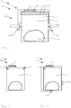
- the Figure 1 shows a domestic appliance 1, which is designed here as a cooking appliance 100.
- the cooking appliance 100 has a treatment space 3 designed as a cooking space 13.
- a treatment device 2 is provided for treating the items to be treated 200.
- the treatment device 2 comprises a thermal heating source 103 and a heating device 12.
- the heating device 12 is provided for dielectric heating of the material to be treated 200 and is designed here as a microwave heating source.
- the cooking space 13 can be closed by a door 104.
- a safety device not shown here, is provided, which prevents operation of the heating device 12 when the door is open, so that an escape of microwave radiation is counteracted.
- further heating sources such as, for example, an upper heating element and a lower heating element or a steam heating source or the like, can be provided.
- the cooking appliance 100 can be operated via an operating device 6.
- the temperature in the cooking chamber 13 can be set during the treatment process.
- the domestic appliance 1 also has a measuring system 4, which is shown here in a highly schematic manner.
- the measuring system 4 is provided for the contactless determination of various characteristic parameters of the item 200 to be treated.
- the treatment device 2 is controlled as a function of the determined parameters.
- One parameter can be, for example, the internal temperature of the items to be treated 200.
- the measuring system 4 can, for. B. also determine the distribution of resonance modes at certain frequencies in the treatment room.
- the measuring system 4 comprises a transmitting device 14, a receiving device 24, a processing device 5 and a storage device 7.
- the transmitting device 14 is suitable and designed to generate electromagnetic measurement radiation and to send it into the treatment room. In this case, at least part of the measurement radiation interacts with the item to be treated 200, not shown here, and is reflected again by it. The reflected measurement radiation is received by the receiving device 24.
- At least one characteristic variable for a wave property of the received measuring radiation is detected by the measuring system 4. For example, the amplitude, frequency, phase or polarization or angle of rotation is recorded as a wave property.
- the processing device 5 determines the characteristic parameters of the material to be treated 200 from the change in the wave properties of the received measurement radiation in relation to the transmitted measurement radiation be.
- the determined parameters are taken into account in the treatment of the items 200 to be treated.
- the treatment device 2 is controlled as a function of the determined parameters.
- the treatment device 2 is with the Measuring system 4 actively connected. It is possible that further control devices, not shown here, are provided.
- the temperature in the interior of the items to be treated 200 can be determined as a parameter. Depending on this temperature, the heating power of the thermal heating source 103 can then be adjusted accordingly.
- the heating power of the heating source 103 is regulated in such a way that optimal temperature conditions prevail in the cooking space 13 for cooking the roast.
- target parameters specified by the user can also be taken into account.
- the user can e.g. B. pretend whether he wants a particularly crispy roast crust.
- the temperature of the thermal heating source 103 is increased or a grill heating source is switched on when the measuring system 4 determines a temperature in the interior of the roast which corresponds to a finished cooking point.
- a household appliance 1 is shown in a highly schematic, sectional side view.
- the domestic appliance 1 is here a cooking appliance 100 with a treatment space 3 designed as a cooking space 13.
- the treatment device 2 comprises a thermal heating source 103, the output of which is regulated by a control device 42.
- the control device 42 is also operatively connected to the measuring system 4.
- the measuring system 4 is designed as a reflectometer device 54, which is designed as a one-port reflectometer.
- the transmitting device 14 and the receiving device 24 are housed together in a reflectometer antenna, which thus simultaneously serves as a transmitter and receiver.
- the reflectometer device 54 is also designed here as a broadband radar reflectometer.
- electromagnetic measurement radiation is generated and sent, which preferably lies in a frequency band that is at least 10 gigahertz wide.
- the frequency band here is 15 gigahertz or 20 gigahertz or more wide.
- the measuring radiation comprises at least two frequencies and preferably a plurality of frequencies. At least two of the frequencies differ by at least 100 gigahertz or more.
- the measuring radiation can preferably also have a frequency width of 10% or more of the center frequency of the frequency band used.
- the measuring radiation is sent from the transmission device 14 into the treatment room 3.
- the measurement radiation interacts, among other things, with the item 200 to be treated and is reflected by it.
- the reflected measurement radiation is detected by the receiving device 24.
- Two independent variables are measured here, e.g. B. Amount and Phase.
- the processing device 5 uses the detected variables to determine the Frequency dependence of the ratio of the radiant power sent into the treatment room 3 to the reflected radiant power.
- the measured variables can be designated, for example, with the scatter parameter S11, as they are also known from vector network analyzers.
- the processing device 5 first calculates the real part components and the imaginary part components of the complex permittivity epsilon for each measurement frequency from the measured, frequency-dependent scattering parameter S11 (as complex numbers, contain two independent measured variables).
- the complex S11 can be converted into a complex epsilon.
- the permittivity describes the properties of the material in interaction with the measurement radiation for the item to be treated 200 on which the measurement radiation was reflected. This interaction is dependent, among other things, on the temperature of the material to be treated 200, which can advantageously be used to determine the temperature.
- the real part and the imaginary part of the complex permittivity are computationally considered by the processing device 5 in a Cole-Cole diagram.
- a circular arc with a center point on the axis can be described for the real part.
- the temperature of the item to be treated 200 results from the radius of the circle or the position of the center of the circle on the real part axis.
- the values for the radius or center of the circle are then compared by the processing device 5 with corresponding reference values which are stored in the memory device 7 of the measuring system 4.
- the reference value is, for example, a value for the radius of the circular arc or the position of the center of the circle on the real part axis of a known substance at defined temperatures. Reference values obtained by measuring defined items to be treated or by corresponding simulations are also possible. If the item to be treated 200 is a food, for example, reference values for water or objects containing water provide correspondingly comparable results for the temperature determination on the basis of the typical water content of food.
- the corresponding measurement points for the permittivity are as far away as possible on the circle radius.
- the methods presented here as well as the household appliances are particularly advantageous because a broadband radar reflectometer or ultra-broadband radars are used.
- the broadband measurement radiation used here enables the corresponding measurement points for the permittivity to be far apart in terms of frequency, so that a corresponding accuracy and reliability of the temperature determination is possible.
- the broadband measurement radiation is that a correspondingly few measurement points are sufficient for a reliable temperature determination.
- the measurement points are so far away on the circle radius that a reliable construction of the circle center z. B. is possible by secant formation and establishment of the vertical center line.
- the center of the circle lies at the intersection of the vertical line on the secant.
- the center of the circle can also result from the mean value of the points of intersection of all perpendicular lines on the secants with the axis for the real part of the permittivity.
- the additional information that the center point must lie on the real part axis is used here. It is also possible to fit a circle into all existing measuring points for the permittivity or to calculate approximately. The center point or circle radius is then calculated from this circle.
- the broadband measurement radiation enables measurement points to be recorded which are so far apart on the circle radius that the secants are as long as possible.
- Such methods have the advantage that the entire frequency band does not have to be scanned to map the semicircle, but only a few measuring points from which the circle can then be calculated.
- a frequency band of around 1000 gigahertz is required to image a complete semicircle at 0 ° C.
- measurements in such a broad frequency band require a very high level of technical effort.
- the previously presented method enables a considerably less complex temperature determination, since a narrower band with fewer frequencies to be scanned can be used.
- a reliable temperature determination of water or aqueous treatment items 200 is possible by means of measured values from a frequency band around only 10 gigahertz. Depending on the required accuracy, a lower or a higher frequency range is also possible. The method therefore requires only a correspondingly low level of technical effort, so that it can also be used economically in conventional household appliances.
- Another advantage of viewing in a Cole-Cole diagram is that it is relatively safe to infer the circle from a comparatively small partial circle segment, because it is known that it is a circle and not an ellipse or another indeterminate course of function.
- the reflectometer device 54 can also be designed as a two-port or multi-port reflectometer device 54.
- further transmitting devices 14 or receiving devices 24 can be provided.
- the principle of transmission measurement is also possible. This can be particularly advantageous in the case of certain geometric conditions in the treatment room 3.
- the transmission through the material to be treated 200 also accessible for measurement.
- the scattering parameters S11, the scattering parameters S12, S21 and S22 can also be determined.
- Two or more reflectometer antennas can also be provided for this purpose. If there are more than two antennas, a variant is to operate them in pairs and to determine reflection and transmission for each pair.
- the household appliance 1 shown here can, as an alternative to the reflectometer device 54, also be designed with an ultra-broadband radar device 44, as it is e.g. B. in the Fig. 3 is described.
- the transmitting device 24 is only opened for a specific time window.
- the processing device 5 only takes into account measurement radiation from a specific time window.
- the time window preferably only comprises the duration of the reflex from the material to be treated 200.
- the receiving device 24 or the processing device 5 is synchronized with the transmitting device 14 for generating the pulse.
- Such a method and the domestic appliance 1 designed for such a method enable a very reliable and contactless temperature determination of the item 200 to be treated.
- a particular advantage is that the temperature inside an object or item 200 can be measured without contact. With knowledge of the internal temperature or the volume temperature, the treatment process and the treatment device 2 can be influenced in a particularly targeted manner. For example, the heating source 103 is controlled in such a way that the material to be treated 200 has an optimal temperature for the respective treatment.
- the volume temperature generally correlates very closely with the required cooking time of a product to be cooked. This enables very reliable control of automatic functions.
- the Figure 3 time a household appliance 1 in a highly schematic side view.
- the domestic appliance 1 is designed here as a cooking appliance 100.
- the treatment space 3 is a cooking space 13 and can be heated by a treatment device 2 designed as a thermal heating source 103.
- the heating source 103 is operatively connected to a control device 42 and can through these are regulated.
- the measuring system 4 is provided for determining characteristic parameters of the material to be treated 200 and is designed as an ultra-broadband radar device 44.
- the ultra-wideband radar device 44 here has two antennas 440, 441 opposite one another.
- each antenna comprises a transmitting device 14, 140 and a receiving device 24, 240.
- the antenna 440, 441 can thus work as a transmitter and receiver.
- the bandwidth of the radar is preferably greater than 250 megahertz and preferably greater than 10% of the center frequency of the frequency band used.
- a frequency band which has been released for such ultra-broadband applications is particularly preferably used.
- a particularly preferred frequency range is, for example, from 100 megahertz to 30 gigahertz or even 100 gigahertz.
- the measuring system 4 generates measuring radiation and sends it out into the treatment room 3 and to the item 200 to be treated. A part of the measurement radiation is reflected by the material to be treated 200 and runs back to the antenna 440, 441 from which the measurement radiation was emitted. Another part of the measurement radiation is transmitted by the material to be treated 200 and passed through to the antenna 440, 441 opposite. It is thus possible to detect measurement radiation reflected and transmitted by the item 200 to be treated.
- the measuring system 4 detects at least one characteristic variable for a wave property of the received measuring radiation, such as. B. the amplitude, frequency, phase or polarization or angle of rotation.
- the characteristic parameter of the material to be treated 200 is determined on the basis of the change in the wave property of the received measurement radiation in relation to the transmitted measurement radiation. The change relates in particular to the phase and / or the amplitude and / or other characteristic parameters and can be described, for example, by corresponding scatter parameters.
- the processing device 5 calculates the real part and the imaginary part of the complex permittivity from the recorded wave properties.
- the processing device 5 takes into account the frequency of the transmitted or received measurement radiation, so that the complex permittivity or its real part or imaginary part can be determined as a function of the respective frequency or as a function of the frequency.
- the most varied of characteristic parameters for the material to be treated 200 can be calculated by the processing device 5.
- the outer contour of the item to be treated 200, the temperature distribution or the moisture distribution inside the item to be treated 200, the material composition, the density distribution and numerous other properties of the Items to be treated 200, which can interact with electromagnetic measurement radiation, are shown.
- a wide variety of parameters can be spatially resolved or determined or represented in an integrated manner over the volume of the items to be treated 200. So z. B. from the integral moisture content in the material to be treated 200 over the treatment time of the moisture loss of the material to be treated 200 and thus z. B. the cooking process can be determined.
- the transmission devices 14, 140 of the ultra-wideband radar device 44 are designed here to transmit ultra-short pulses.
- the duration of the pulses is in the picosecond range.
- the pulses have correspondingly steep edges.
- a correspondingly large bandwidth of typically a few GHz and z. B. of 10 or 20 GHz or more can be described.
- the receiving devices 24, 240 are designed to receive the broadband pulses. In this case, the receiving devices 24, 240 only detect the measurement radiation which lies in a specific time window.
- the time window begins at an adjustable time after the transmission pulse has been sent. Such a time window makes it possible to determine from which spatial area of the treatment room 3 or of the item 200 the received measurement signal originates.
- the impulse is influenced by the interaction with the material to be treated 200 in such a way that characteristic wave variables such as the phase or amplitude change.
- the changes are recorded by the measuring system 4 and evaluated by the processing device 5 as a function of time, so that the electrical properties of the item to be treated can be determined in precisely the spatial area from which the received measuring radiation originates.
- the spatial resolution is larger or smaller depending on the frequency bandwidth used for the measurement radiation. If, for example, the spatial resolution is to be less detailed, a lower frequency bandwidth can be used or the spatial information can be averaged.
- the Figure 4 shows a highly schematic representation of a further domestic appliance in a side view.
- the measuring system here has an ultra-wideband radar device 44, which has a pivotable transmitter device 14 and a pivotable receiver device 24.
- the pivoting enables a spatially resolved description of characteristic parameters of the material to be treated 200 with only one transmitting device 14 and one receiving device 24.
- the receiving device 24 is preferably pivoted in a spacing grid along the item 200 to be treated.
- the transmitting device 14 retains its position. At each pivot position of the receiving device 24, measurement radiation is recorded over the entire observed frequency band.
- the receiving device 24 has a time window for the reception of the measurement radiation reflected and transmitted on the item to be treated, which is preferably passed through completely once.
- the transmitting device 14 is then moved, the receiving device 24 being pivoted again along the spacing grid at this new position.
- FIG. 4 shows a further embodiment of a measuring system 4 with an ultra-wideband radar device 44.
- the measuring system presented here is equipped with movable receiving devices 24, 240.
- the transmitting device 14 is pivotable. During a measurement process, the transmitting device 14 assumes a specific pivot position, while the receiving devices 24, 240 are moved along the item 200 to be treated.
- the receiving devices 24, 240 are preferably moved along a predetermined spacing grid. Other combinations of stationary, movable and / or pivotable transmitting devices 14 or receiving devices are also possible.
- a domestic appliance 1 is shown with a measuring system 4 which enables the distribution of the radiation power in the treatment room 3 to be determined. For example, cavity resonances are determined as a function of frequency.
- the treatment space is designed as a cooking space 13.
- the electrical heating device 12 is provided for heating the cooking space 13.
- the heating device 12 has an oscillator device 52 and an amplifier device 62, which together generate and amplify electromagnetic radiation power for heating the cooking space 13.
- the heating device 12 is controlled by a control device 42.
- the measuring system 4 is designed here as an ultra-wideband radar device 44 and has a transmitting device 14, a receiving device 24 and a processing device 5.
- the measuring system 4 works essentially similarly to that in FIG Figure 3
- the measuring system 4 shown here determines a spatial power distribution of electromagnetic radiation on the basis of the change in the wave properties of the received measuring radiation in relation to the transmitted measuring radiation.
- the power of the measurement radiation absorbed by the treatment room 3 and / or by the item 200 to be treated is determined as a function of the frequency.
- the measuring system can also be a Have ultra-wideband radar device 44 or a reflectometer device 54, as previously described.
- the common cavity resonances of the treatment room 3 and the items to be treated 200 can be determined for this frequency.
- the ultrashort pulses emitted as measurement radiation range from picoseconds to nanoseconds or microseconds.
- the frequency bandwidths associated with the Fourier transformation are in particular in the range of a few 10MHz to 1 THz.
- the pulse duration is advantageously selected such that the reflected measuring radiation in the treatment room 3 is not superimposed with the incoming pulse on the way to the receiving device 24.
- the pulse length is selected to be so short that multiple reflections from different areas of the treatment room 3 can be discriminated against reflections on the treatment room 200.
- the time window is preferably set as described above.
- the frequency-dependent difference between the transmitted and received power of the measurement radiation results in cavity resonances at certain frequencies.
- a particularly large amount of radiation power is absorbed by the item 200 and the treatment space 3.
- the treatment room 3 which is usually lined with metal, shows an absorption that is negligible compared to the item 200 to be treated.
- the cavity resonances are interpreted in particular in such a way that they describe the field distribution or the spatial distribution of the electromagnetic power supply within the treatment room and in particular within the item 200 to be treated.
- the cavity resonances therefore decisively determine the temperature distribution in the material to be treated 200.
- the cavity resonances thus described by the measuring system 4 can essentially also be transferred to the radiant power supplied by the heating device 12 into the treatment room 3.
- a prediction can therefore be made as to which cavity resonances will occur when the heating device is active.
- Such a measurement method thus has the advantage that the spatial distribution of the radiant powers that can be supplied by the heating device 12 can be precisely described for a given item 200 in a treatment room 3.
- the power supply to the material to be treated 200 can be specifically influenced, e.g. B. by stirrer or alignment of the material to be treated 200.
- the complex permittivity is preferably determined for each measurement frequency in the frequency band of the ultra-wideband radar device 44.
- the absorption, reflection and transmission of electromagnetic radiation power of the respective frequency can thus be determined for the item 200 to be treated.
- the domestic appliance 1 shown here also has the advantage that the heating device 12 can be controlled in accordance with the previously determined spatial power distribution.
- the oscillator device 52 can be used to generate radiant power with the specific frequency or in a specific frequency range.
- the oscillator device 52 is operatively connected to the control device 42 and can be controlled by it.
- the frequency of the radiant power emitted by the heating device can be set as a function of the power distribution determined by the measuring system or the determined cavity resonances.
- a frequency is selected for which the item to be treated has previously shown a high or low absorption capacity in the measurement run. It is also possible that the heating device 12 emits radiant power at different frequencies over time, so that certain field distributions or cavity resonances can be superimposed one after the other in time. With knowledge of the spatial absorption capacity of the items to be treated 200, it is also possible to supply certain areas of the items to be treated 200 with a high radiation power and to administer a correspondingly low radiation power to other areas. For example, food to be cooked can be heated more intensely in an inner area than in an outer area.
- FIG. 3 shows a domestic appliance 1 embodied as a cooking appliance 100 with a measuring system 4.
- the measuring system 4 essentially corresponds to the measuring system 4, as shown in FIG Figure 6 has been described.
- the heating device 12 here has a transmission device 22.
- the transmission device 22 is connected to the heating device 12 via a waveguide device 72.
- the transmission device 22 is provided here to distribute the electromagnetic radiation power generated by the heating device 12 in the treatment room 3.
- the transmission device 22 can be designed, for example, as a stirrer or impeller or the like.
- metallic conductive sheets are provided, which are moved by a motor and lead to a deflection of the radiation power sent into the treatment room 3.
- different vibration modes or cavity resonances are achieved in the treatment room 3.
- the cooking appliance 100 also has a positioning device 32 here.
- the positioning is designed, for example, as a rotary plate and is used to position or move the items 200 in the treatment room 3.
- the transmission device 22 is operatively connected here to a control device 42, which in turn is operatively connected to the measuring system 4.
- the transmission device 22 can be controlled as a function of the information ascertained by the measuring system.
- the transmission device 22 is preferably aligned in such a way that a desired power supply to the material to be treated 200 is achieved.
- z. B. programs set by the user or other targets are taken into account.
- the change in the cavity resonances in the treatment room 3 after the position of the transmission device 22 has been changed can be monitored by the measuring system 4.
- the measuring system 4 transmits the cavity resonances again when the transmission device 22 has been changed.
- the positioning device 32 can be set as a function of the cavity resonances determined by the measuring system 4.
- different resonances in the treatment room 3 can be realized in a targeted manner in time.
- different spatial distributions for the input of power into the material to be treated 200 can also be implemented.
- the dwell times when approaching a specific cavity resonance are described in particular by a weighted sum. It is determined how long each resonance has to be approached for an optimal result. It can also be determined how the corresponding cavity resonance is to be realized, so z. B. by the positioning device 32 or by a corresponding setting of the transmission device 22.
- the desired cavity resonance can also be approached in that the heating device 12 emits radiant power at a certain frequency, as is the case, for example, for the cooking appliance 100 in FIG Figure 6 has been described.
- the information contained in the weighted sum can preferably have been determined in advance by a simulation or also by experiments.
- This information and other previously determined parameters of a power distribution are preferably stored as reference parameters in a memory device of the domestic appliance 1. When the user selects a corresponding automatic program or another target specification, the reference parameters can then be called up, adapted to the situation.
Landscapes
- Physics & Mathematics (AREA)
- Electromagnetism (AREA)
- Electric Ovens (AREA)
- Constitution Of High-Frequency Heating (AREA)
Claims (8)
- Procédé de fonctionnement d'un appareil ménager (1) comportant au moins un dispositif de traitement (2) permettant de traiter des articles à traiter (200) dans au moins un espace de traitement (3), la température d'au moins une partie de l'article à traiter (200) étant déterminée sans contact au moyen d'au moins un système de mesure (4) comportant au moins un dispositif d'assimilation (5) et le dispositif de traitement (2) étant commandé en fonction de la température déterminée,
le système de mesure (4) générant un rayonnement électromagnétique au moins temporairement et introduisant ce dernier dans l'espace de traitement (3) au moyen d'au moins un dispositif émetteur (14), et un rayonnement de mesure, lequel interagit avec l'article à traiter (200) et est directement réfléchi, étant reçu au moins temporairement par au moins un dispositif récepteur (24) du système de mesure (4), le système de mesure étant conçu pour émettre et recevoir des signaux à bande ultra-large avec une largeur de fréquence d'au moins 250 MHz et fonctionnant comme tel, et caractérisé en ce que le dispositif émetteur (14) émet à plusieurs reprises le rayonnement de mesure sous forme d'au moins une impulsion ultra-courte avec une durée d'impulsion inférieure à une nanoseconde, le système de mesure détectant au moins la phase et l'amplitude comme propriétés d'onde du rayonnement de mesure reçu en tenant compte de la fréquence, le dispositif d'assimilation (5) déterminant la permittivité complexe en fonction du changement de la propriété d'onde du rayonnement de mesure reçu par rapport au rayonnement de mesure émis et considère celle-ci comme fonction de la fréquence, la température étant dérivée à l'aide de la dépendance en fréquence d'une valeur maximale de la fonction. - Procédé selon la revendication précédente, caractérisé en ce que la dépendance en fréquence déterminée de la permittivité complexe est comparée avec au moins un paramètre de référence stocké dans au moins un dispositif de stockage (7), le paramètre de référence décrivant la dépendance en fréquence de la permittivité complexe d'au moins une substance et/ou un corps connus à au moins une température définie.
- Procédé selon l'une des deux revendications précédentes, caractérisé en ce que la partie réelle et la partie imaginaire de la permittivité complexe sont vues comme une courbe spatiale dans un diagramme de Cole-Cole, de sorte qu'un arc de cercle comportant un point central sur l'axe peut être décrit pour la partie réelle, la température étant déterminée à l'aide du centre du cercle ou du rayon de cercle.
- Procédé selon la revendication précédente, caractérisé en ce que le rayon de l'arc de cercle ou la position du centre du cercle sur l'axe pour la partie réelle sont comparés avec au moins une valeur de référence stockée dans au moins un dispositif de stockage (7) d'au moins une matière et/ou un corps connus à au moins une température définie.
- Procédé selon l'une des revendications précédentes, caractérisé en ce que le rayonnement de mesure est émis à plusieurs reprises.
- Procédé selon l'une des revendications précédentes, caractérisé en ce que le rayonnement de mesure comprend au moins deux fréquences différant d'au moins 100 MHz et comprises entre 10 mégahertz et 1 térahertz.
- Procédé selon l'une des revendications précédentes, caractérisé en ce que le rayonnement de mesure présente une largeur de fréquence d'au moins 10 % de la fréquence centrale de la bande de fréquences utilisée.
- Procédé selon l'une des revendications précédentes, caractérisé en ce que le rayonnement de mesure reçu par le dispositif récepteur (24) est analysé par le dispositif d'assimilation (5) et en ce que le rayonnement de mesure qui a été reçu pendant une fenêtre temporelle définie est pris en compte, le début de la fenêtre temporelle dépendant au moins partiellement du moment à partir duquel le rayonnement de mesure est émis.
Applications Claiming Priority (1)
| Application Number | Priority Date | Filing Date | Title |
|---|---|---|---|
| DE102014105255.2A DE102014105255A1 (de) | 2014-04-14 | 2014-04-14 | Verfahren und Hausgerät |
Publications (2)
| Publication Number | Publication Date |
|---|---|
| EP2941092A1 EP2941092A1 (fr) | 2015-11-04 |
| EP2941092B1 true EP2941092B1 (fr) | 2021-05-12 |
Family
ID=52875471
Family Applications (1)
| Application Number | Title | Priority Date | Filing Date |
|---|---|---|---|
| EP15161072.2A Active EP2941092B1 (fr) | 2014-04-14 | 2015-03-26 | Procédé et appareil ménager |
Country Status (2)
| Country | Link |
|---|---|
| EP (1) | EP2941092B1 (fr) |
| DE (1) | DE102014105255A1 (fr) |
Families Citing this family (4)
| Publication number | Priority date | Publication date | Assignee | Title |
|---|---|---|---|---|
| DE102016113216B3 (de) * | 2016-07-18 | 2017-11-09 | Hochschule Ruhr West | Verfahren zur berührungslosen Bestimmung der Temperatur eines Garguts in einem Gargerät sowie Gargerät |
| DE102016122557A1 (de) | 2016-11-23 | 2018-05-24 | Miele & Cie. Kg | Verfahren und Gargerät |
| EP3521787A1 (fr) * | 2018-01-31 | 2019-08-07 | ETH Zurich | Revêtements historiques thermiques ultra-minces basés sur de fortes interférences |
| CN113728215A (zh) * | 2019-04-30 | 2021-11-30 | Gea 食品策划巴克尔公司 | 改进的温度测量 |
Family Cites Families (3)
| Publication number | Priority date | Publication date | Assignee | Title |
|---|---|---|---|---|
| US5237141A (en) * | 1990-07-17 | 1993-08-17 | Matsushita Electric Industrial Co., Ltd. | High frequency heating apparatus and electromagnetic wave detector for use in high frequency heating apparatus |
| WO2013078325A1 (fr) * | 2011-11-22 | 2013-05-30 | Goji Ltd. | Commande d'une application d'énergie radiofréquence sur la base de la température |
| JPWO2014103633A1 (ja) * | 2012-12-26 | 2017-01-12 | 東京エレクトロン株式会社 | 電磁波加熱装置および電磁波加熱方法 |
-
2014
- 2014-04-14 DE DE102014105255.2A patent/DE102014105255A1/de not_active Withdrawn
-
2015
- 2015-03-26 EP EP15161072.2A patent/EP2941092B1/fr active Active
Non-Patent Citations (1)
| Title |
|---|
| None * |
Also Published As
| Publication number | Publication date |
|---|---|
| DE102014105255A1 (de) | 2015-10-15 |
| EP2941092A1 (fr) | 2015-11-04 |
Similar Documents
| Publication | Publication Date | Title |
|---|---|---|
| EP2983453A1 (fr) | Procede et appareil menager | |
| EP3446544B1 (fr) | Système de préparation et procédé de fonctionnement d'un système pour la préparation d'au moins un aliment | |
| EP2941092B1 (fr) | Procédé et appareil ménager | |
| WO2021008825A1 (fr) | Procédé pour le fonctionnement d'un appareil de cuisson et appareil de cuisson | |
| EP2938161A1 (fr) | Procédé et appareil ménager | |
| EP3258742B1 (fr) | Procédé destiné au fonctionnement d'un appareil de cuisson et appareil de cuisson | |
| EP3324123B1 (fr) | Procédé de chauffage d'un liquide en reconnaissance d'un point d'ébullition | |
| EP4260659A1 (fr) | Fonctionnement d'un appareil à micro-ondes domestique | |
| EP3327356B1 (fr) | Appareil de cuisson et procédé de fonctionnement d'appareil de cuisson | |
| EP3451795B1 (fr) | Procédé de cuisson des aliments à cuire dans l'espace de cuisson d'un appareil de cuisson | |
| DE102012013936A1 (de) | Gargerät mit Einschuberkennung | |
| DE102018202519B4 (de) | Verfahren zum Betreiben eines Haushaltsgeräts mit Auftaufunktion und Haushaltsgerät zum Durchführen des Verfahrens | |
| DE102019119071A1 (de) | Verfahren zum Betreiben eines Geräts, insbesondere Gargerät oder Trocknungsgerät, und Gerät | |
| DE102016116120B4 (de) | Verfahren zum Betreiben eines Gargerätes und Gargerät | |
| DE102017100074B4 (de) | Verfahren zum Behandeln von Gargut und Gargerät zur Durchführung eines solchen Verfahrens | |
| DE10063692C2 (de) | Verfahren und Vorrichtung zum Messen und Überwachen von erwärmungsbedingten Veränderungen von Substanzen in einem Backofen | |
| EP3253179A1 (fr) | Procédé destiné au fonctionnement d'un appareil de cuisson et appareil de cuisson | |
| DE102019125551B4 (de) | Verfahren zum Analysieren des Absorptionsverhaltens eines Objekts, Verfahren zum Betrieb eines Gargeräts sowie Analysegerät | |
| EP3405005B1 (fr) | Procédé et dispositif de cuisson destinés à cuire des produits à cuire | |
| DE102016113216B3 (de) | Verfahren zur berührungslosen Bestimmung der Temperatur eines Garguts in einem Gargerät sowie Gargerät | |
| EP3364719B1 (fr) | Procédé de cuisson d'article à cuire et dispositif de cuisson | |
| EP4008962A1 (fr) | Procédé de fonctionnement d'un appareil de cuisson et appareil de cuisson | |
| EP3756420B1 (fr) | Procédé de fonctionnement d'un dispositif de chauffage d'aliments et dispositif de chauffage d'aliments | |
| DE102023132239A1 (de) | Kabelloser Kerntemperaturfühler sowie Gargerät |
Legal Events
| Date | Code | Title | Description |
|---|---|---|---|
| PUAI | Public reference made under article 153(3) epc to a published international application that has entered the european phase |
Free format text: ORIGINAL CODE: 0009012 |
|
| AK | Designated contracting states |
Kind code of ref document: A1 Designated state(s): AL AT BE BG CH CY CZ DE DK EE ES FI FR GB GR HR HU IE IS IT LI LT LU LV MC MK MT NL NO PL PT RO RS SE SI SK SM TR |
|
| AX | Request for extension of the european patent |
Extension state: BA ME |
|
| 17P | Request for examination filed |
Effective date: 20160504 |
|
| RBV | Designated contracting states (corrected) |
Designated state(s): AL AT BE BG CH CY CZ DE DK EE ES FI FR GB GR HR HU IE IS IT LI LT LU LV MC MK MT NL NO PL PT RO RS SE SI SK SM TR |
|
| STAA | Information on the status of an ep patent application or granted ep patent |
Free format text: STATUS: EXAMINATION IS IN PROGRESS |
|
| 17Q | First examination report despatched |
Effective date: 20180511 |
|
| GRAP | Despatch of communication of intention to grant a patent |
Free format text: ORIGINAL CODE: EPIDOSNIGR1 |
|
| STAA | Information on the status of an ep patent application or granted ep patent |
Free format text: STATUS: GRANT OF PATENT IS INTENDED |
|
| INTG | Intention to grant announced |
Effective date: 20210208 |
|
| GRAS | Grant fee paid |
Free format text: ORIGINAL CODE: EPIDOSNIGR3 |
|
| GRAA | (expected) grant |
Free format text: ORIGINAL CODE: 0009210 |
|
| STAA | Information on the status of an ep patent application or granted ep patent |
Free format text: STATUS: THE PATENT HAS BEEN GRANTED |
|
| REG | Reference to a national code |
Ref country code: DE Ref legal event code: R084 Ref document number: 502015014702 Country of ref document: DE |
|
| AK | Designated contracting states |
Kind code of ref document: B1 Designated state(s): AL AT BE BG CH CY CZ DE DK EE ES FI FR GB GR HR HU IE IS IT LI LT LU LV MC MK MT NL NO PL PT RO RS SE SI SK SM TR |
|
| REG | Reference to a national code |
Ref country code: GB Ref legal event code: FG4D Free format text: NOT ENGLISH |
|
| REG | Reference to a national code |
Ref country code: CH Ref legal event code: EP |
|
| REG | Reference to a national code |
Ref country code: DE Ref legal event code: R096 Ref document number: 502015014702 Country of ref document: DE |
|
| REG | Reference to a national code |
Ref country code: IE Ref legal event code: FG4D Free format text: LANGUAGE OF EP DOCUMENT: GERMAN |
|
| REG | Reference to a national code |
Ref country code: AT Ref legal event code: REF Ref document number: 1393049 Country of ref document: AT Kind code of ref document: T Effective date: 20210615 |
|
| REG | Reference to a national code |
Ref country code: LT Ref legal event code: MG9D |
|
| REG | Reference to a national code |
Ref country code: NL Ref legal event code: MP Effective date: 20210512 |
|
| PG25 | Lapsed in a contracting state [announced via postgrant information from national office to epo] |
Ref country code: BG Free format text: LAPSE BECAUSE OF FAILURE TO SUBMIT A TRANSLATION OF THE DESCRIPTION OR TO PAY THE FEE WITHIN THE PRESCRIBED TIME-LIMIT Effective date: 20210812 Ref country code: FI Free format text: LAPSE BECAUSE OF FAILURE TO SUBMIT A TRANSLATION OF THE DESCRIPTION OR TO PAY THE FEE WITHIN THE PRESCRIBED TIME-LIMIT Effective date: 20210512 Ref country code: LT Free format text: LAPSE BECAUSE OF FAILURE TO SUBMIT A TRANSLATION OF THE DESCRIPTION OR TO PAY THE FEE WITHIN THE PRESCRIBED TIME-LIMIT Effective date: 20210512 Ref country code: HR Free format text: LAPSE BECAUSE OF FAILURE TO SUBMIT A TRANSLATION OF THE DESCRIPTION OR TO PAY THE FEE WITHIN THE PRESCRIBED TIME-LIMIT Effective date: 20210512 |
|
| PG25 | Lapsed in a contracting state [announced via postgrant information from national office to epo] |
Ref country code: GR Free format text: LAPSE BECAUSE OF FAILURE TO SUBMIT A TRANSLATION OF THE DESCRIPTION OR TO PAY THE FEE WITHIN THE PRESCRIBED TIME-LIMIT Effective date: 20210813 Ref country code: IS Free format text: LAPSE BECAUSE OF FAILURE TO SUBMIT A TRANSLATION OF THE DESCRIPTION OR TO PAY THE FEE WITHIN THE PRESCRIBED TIME-LIMIT Effective date: 20210912 Ref country code: LV Free format text: LAPSE BECAUSE OF FAILURE TO SUBMIT A TRANSLATION OF THE DESCRIPTION OR TO PAY THE FEE WITHIN THE PRESCRIBED TIME-LIMIT Effective date: 20210512 Ref country code: NO Free format text: LAPSE BECAUSE OF FAILURE TO SUBMIT A TRANSLATION OF THE DESCRIPTION OR TO PAY THE FEE WITHIN THE PRESCRIBED TIME-LIMIT Effective date: 20210812 Ref country code: PT Free format text: LAPSE BECAUSE OF FAILURE TO SUBMIT A TRANSLATION OF THE DESCRIPTION OR TO PAY THE FEE WITHIN THE PRESCRIBED TIME-LIMIT Effective date: 20210913 Ref country code: PL Free format text: LAPSE BECAUSE OF FAILURE TO SUBMIT A TRANSLATION OF THE DESCRIPTION OR TO PAY THE FEE WITHIN THE PRESCRIBED TIME-LIMIT Effective date: 20210512 Ref country code: ES Free format text: LAPSE BECAUSE OF FAILURE TO SUBMIT A TRANSLATION OF THE DESCRIPTION OR TO PAY THE FEE WITHIN THE PRESCRIBED TIME-LIMIT Effective date: 20210512 Ref country code: RS Free format text: LAPSE BECAUSE OF FAILURE TO SUBMIT A TRANSLATION OF THE DESCRIPTION OR TO PAY THE FEE WITHIN THE PRESCRIBED TIME-LIMIT Effective date: 20210512 Ref country code: SE Free format text: LAPSE BECAUSE OF FAILURE TO SUBMIT A TRANSLATION OF THE DESCRIPTION OR TO PAY THE FEE WITHIN THE PRESCRIBED TIME-LIMIT Effective date: 20210512 |
|
| PG25 | Lapsed in a contracting state [announced via postgrant information from national office to epo] |
Ref country code: NL Free format text: LAPSE BECAUSE OF FAILURE TO SUBMIT A TRANSLATION OF THE DESCRIPTION OR TO PAY THE FEE WITHIN THE PRESCRIBED TIME-LIMIT Effective date: 20210512 |
|
| PG25 | Lapsed in a contracting state [announced via postgrant information from national office to epo] |
Ref country code: RO Free format text: LAPSE BECAUSE OF FAILURE TO SUBMIT A TRANSLATION OF THE DESCRIPTION OR TO PAY THE FEE WITHIN THE PRESCRIBED TIME-LIMIT Effective date: 20210512 Ref country code: SM Free format text: LAPSE BECAUSE OF FAILURE TO SUBMIT A TRANSLATION OF THE DESCRIPTION OR TO PAY THE FEE WITHIN THE PRESCRIBED TIME-LIMIT Effective date: 20210512 Ref country code: SK Free format text: LAPSE BECAUSE OF FAILURE TO SUBMIT A TRANSLATION OF THE DESCRIPTION OR TO PAY THE FEE WITHIN THE PRESCRIBED TIME-LIMIT Effective date: 20210512 Ref country code: EE Free format text: LAPSE BECAUSE OF FAILURE TO SUBMIT A TRANSLATION OF THE DESCRIPTION OR TO PAY THE FEE WITHIN THE PRESCRIBED TIME-LIMIT Effective date: 20210512 Ref country code: CZ Free format text: LAPSE BECAUSE OF FAILURE TO SUBMIT A TRANSLATION OF THE DESCRIPTION OR TO PAY THE FEE WITHIN THE PRESCRIBED TIME-LIMIT Effective date: 20210512 Ref country code: DK Free format text: LAPSE BECAUSE OF FAILURE TO SUBMIT A TRANSLATION OF THE DESCRIPTION OR TO PAY THE FEE WITHIN THE PRESCRIBED TIME-LIMIT Effective date: 20210512 |
|
| REG | Reference to a national code |
Ref country code: DE Ref legal event code: R097 Ref document number: 502015014702 Country of ref document: DE |
|
| PLBE | No opposition filed within time limit |
Free format text: ORIGINAL CODE: 0009261 |
|
| STAA | Information on the status of an ep patent application or granted ep patent |
Free format text: STATUS: NO OPPOSITION FILED WITHIN TIME LIMIT |
|
| 26N | No opposition filed |
Effective date: 20220215 |
|
| PG25 | Lapsed in a contracting state [announced via postgrant information from national office to epo] |
Ref country code: IS Free format text: LAPSE BECAUSE OF FAILURE TO SUBMIT A TRANSLATION OF THE DESCRIPTION OR TO PAY THE FEE WITHIN THE PRESCRIBED TIME-LIMIT Effective date: 20210912 Ref country code: AL Free format text: LAPSE BECAUSE OF FAILURE TO SUBMIT A TRANSLATION OF THE DESCRIPTION OR TO PAY THE FEE WITHIN THE PRESCRIBED TIME-LIMIT Effective date: 20210512 |
|
| PG25 | Lapsed in a contracting state [announced via postgrant information from national office to epo] |
Ref country code: IT Free format text: LAPSE BECAUSE OF FAILURE TO SUBMIT A TRANSLATION OF THE DESCRIPTION OR TO PAY THE FEE WITHIN THE PRESCRIBED TIME-LIMIT Effective date: 20210512 |
|
| PG25 | Lapsed in a contracting state [announced via postgrant information from national office to epo] |
Ref country code: MC Free format text: LAPSE BECAUSE OF FAILURE TO SUBMIT A TRANSLATION OF THE DESCRIPTION OR TO PAY THE FEE WITHIN THE PRESCRIBED TIME-LIMIT Effective date: 20210512 |
|
| REG | Reference to a national code |
Ref country code: CH Ref legal event code: PL |
|
| GBPC | Gb: european patent ceased through non-payment of renewal fee |
Effective date: 20220326 |
|
| REG | Reference to a national code |
Ref country code: BE Ref legal event code: MM Effective date: 20220331 |
|
| PG25 | Lapsed in a contracting state [announced via postgrant information from national office to epo] |
Ref country code: LU Free format text: LAPSE BECAUSE OF NON-PAYMENT OF DUE FEES Effective date: 20220326 Ref country code: LI Free format text: LAPSE BECAUSE OF NON-PAYMENT OF DUE FEES Effective date: 20220331 Ref country code: IE Free format text: LAPSE BECAUSE OF NON-PAYMENT OF DUE FEES Effective date: 20220326 Ref country code: GB Free format text: LAPSE BECAUSE OF NON-PAYMENT OF DUE FEES Effective date: 20220326 Ref country code: FR Free format text: LAPSE BECAUSE OF NON-PAYMENT OF DUE FEES Effective date: 20220331 Ref country code: CH Free format text: LAPSE BECAUSE OF NON-PAYMENT OF DUE FEES Effective date: 20220331 |
|
| PG25 | Lapsed in a contracting state [announced via postgrant information from national office to epo] |
Ref country code: BE Free format text: LAPSE BECAUSE OF NON-PAYMENT OF DUE FEES Effective date: 20220331 |
|
| REG | Reference to a national code |
Ref country code: AT Ref legal event code: MM01 Ref document number: 1393049 Country of ref document: AT Kind code of ref document: T Effective date: 20220326 |
|
| P01 | Opt-out of the competence of the unified patent court (upc) registered |
Effective date: 20230528 |
|
| PG25 | Lapsed in a contracting state [announced via postgrant information from national office to epo] |
Ref country code: AT Free format text: LAPSE BECAUSE OF NON-PAYMENT OF DUE FEES Effective date: 20220326 |
|
| PG25 | Lapsed in a contracting state [announced via postgrant information from national office to epo] |
Ref country code: HU Free format text: LAPSE BECAUSE OF FAILURE TO SUBMIT A TRANSLATION OF THE DESCRIPTION OR TO PAY THE FEE WITHIN THE PRESCRIBED TIME-LIMIT; INVALID AB INITIO Effective date: 20150326 |
|
| PG25 | Lapsed in a contracting state [announced via postgrant information from national office to epo] |
Ref country code: MK Free format text: LAPSE BECAUSE OF FAILURE TO SUBMIT A TRANSLATION OF THE DESCRIPTION OR TO PAY THE FEE WITHIN THE PRESCRIBED TIME-LIMIT Effective date: 20210512 Ref country code: CY Free format text: LAPSE BECAUSE OF FAILURE TO SUBMIT A TRANSLATION OF THE DESCRIPTION OR TO PAY THE FEE WITHIN THE PRESCRIBED TIME-LIMIT Effective date: 20210512 |
|
| PG25 | Lapsed in a contracting state [announced via postgrant information from national office to epo] |
Ref country code: MT Free format text: LAPSE BECAUSE OF FAILURE TO SUBMIT A TRANSLATION OF THE DESCRIPTION OR TO PAY THE FEE WITHIN THE PRESCRIBED TIME-LIMIT Effective date: 20210512 |
|
| PG25 | Lapsed in a contracting state [announced via postgrant information from national office to epo] |
Ref country code: TR Free format text: LAPSE BECAUSE OF FAILURE TO SUBMIT A TRANSLATION OF THE DESCRIPTION OR TO PAY THE FEE WITHIN THE PRESCRIBED TIME-LIMIT Effective date: 20210512 |
|
| PGFP | Annual fee paid to national office [announced via postgrant information from national office to epo] |
Ref country code: DE Payment date: 20260331 Year of fee payment: 12 |