EP2941987B1 - Dispositif de réception d'ensemble mélangeur portatif et procédé de réception de celui-ci - Google Patents
Dispositif de réception d'ensemble mélangeur portatif et procédé de réception de celui-ci Download PDFInfo
- Publication number
- EP2941987B1 EP2941987B1 EP12890640.1A EP12890640A EP2941987B1 EP 2941987 B1 EP2941987 B1 EP 2941987B1 EP 12890640 A EP12890640 A EP 12890640A EP 2941987 B1 EP2941987 B1 EP 2941987B1
- Authority
- EP
- European Patent Office
- Prior art keywords
- stirring
- accommodating
- head
- transmission
- handheld
- Prior art date
- Legal status (The legal status is an assumption and is not a legal conclusion. Google has not performed a legal analysis and makes no representation as to the accuracy of the status listed.)
- Not-in-force
Links
- 238000000034 method Methods 0.000 title claims description 12
- 238000003756 stirring Methods 0.000 claims description 220
- 230000005540 biological transmission Effects 0.000 claims description 108
- 238000005192 partition Methods 0.000 claims description 36
- 238000005520 cutting process Methods 0.000 claims description 10
- 238000004140 cleaning Methods 0.000 claims description 6
- 239000000126 substance Substances 0.000 claims description 4
- 230000007306 turnover Effects 0.000 claims description 3
- 238000010586 diagram Methods 0.000 description 10
- 239000000428 dust Substances 0.000 description 7
- 230000000712 assembly Effects 0.000 description 2
- 238000000429 assembly Methods 0.000 description 2
- XLYOFNOQVPJJNP-UHFFFAOYSA-N water Substances O XLYOFNOQVPJJNP-UHFFFAOYSA-N 0.000 description 2
- 239000012459 cleaning agent Substances 0.000 description 1
- 238000000354 decomposition reaction Methods 0.000 description 1
- 230000007812 deficiency Effects 0.000 description 1
- 230000000694 effects Effects 0.000 description 1
- 230000014759 maintenance of location Effects 0.000 description 1
- 238000004519 manufacturing process Methods 0.000 description 1
Images



Classifications
-
- A—HUMAN NECESSITIES
- A47—FURNITURE; DOMESTIC ARTICLES OR APPLIANCES; COFFEE MILLS; SPICE MILLS; SUCTION CLEANERS IN GENERAL
- A47J—KITCHEN EQUIPMENT; COFFEE MILLS; SPICE MILLS; APPARATUS FOR MAKING BEVERAGES
- A47J43/00—Implements for preparing or holding food, not provided for in other groups of this subclass
- A47J43/04—Machines for domestic use not covered elsewhere, e.g. for grinding, mixing, stirring, kneading, emulsifying, whipping or beating foodstuffs, e.g. power-driven
- A47J43/06—Machines for domestic use not covered elsewhere, e.g. for grinding, mixing, stirring, kneading, emulsifying, whipping or beating foodstuffs, e.g. power-driven with a plurality of interchangeable working units, e.g. with a single driving-unit
-
- A—HUMAN NECESSITIES
- A47—FURNITURE; DOMESTIC ARTICLES OR APPLIANCES; COFFEE MILLS; SPICE MILLS; SUCTION CLEANERS IN GENERAL
- A47J—KITCHEN EQUIPMENT; COFFEE MILLS; SPICE MILLS; APPARATUS FOR MAKING BEVERAGES
- A47J43/00—Implements for preparing or holding food, not provided for in other groups of this subclass
- A47J43/04—Machines for domestic use not covered elsewhere, e.g. for grinding, mixing, stirring, kneading, emulsifying, whipping or beating foodstuffs, e.g. power-driven
- A47J43/07—Parts or details, e.g. mixing tools, whipping tools
Definitions
- the invention relates to a food handling device, especially a handheld stirrer.
- WO2006/015403 discloses a cordless kitchen appliance comprising a power unit, a detachable blade extension unit and a base module; said power unit and said detachable extension unit adapted for retention in said base module when not in use.
- the invention is intended to solve the technical issues by means of avoiding the deficiencies of the above the prior art, and put forward an accommodating device for a handheld stirrer assembly as well as a method of accommodating the handheld stirrer with the device, where each component of the handheld stirrer can be kept compactly and cleanly, isolated from the dust of the external environment, besides, the device can store the said handheld stirrer assembly with as little space as possible.
- the invention can solve the said technical problem with the following technical proposal: Design and manufacture a device for accommodating a handheld stirrer assembly.
- the said handheld stirrer assembly comprises a handheld portion installed with a drive motor and a control unit, a transmission stirring portion which can be detachably connected to the said handheld portion and transmit the output torque of the handheld portion by virtue of the transmission rod thereof, as well as at least one stirring cutter which can be detachably installed to the transmission rod head of the said transmission stirring portion.
- the said accommodating device comprises an accessory accommodating base, an accommodating and supporting partition cover covering the accessory accommodating base, as well as an accommodating main cover with a measuring cup function covering the said accessory accommodating base and the accommodating and supporting partition cover.
- the said accommodating main cover with a measuring cup function takes on the shape of an upturned bucket.
- the said stirring cutter is placed in a space between the said accessory accommodating base and the accommodating and supporting partition cover.
- the said handheld portion and transmission stirring portion are supported by the accommodating and supporting partition cover, and placed in a space between the accommodating and supporting partition cover and the accommodating main cover with a measuring cup function.
- accessory recesses are processed on the said accessory accommodating base according to the shape of the said stirring cutter, such that the said stirring cutter can be caught in the said accessory recesses, thus the said stirring cutter is securely positioned and placed.
- a main device recesses are processed on the top of the said accommodating and supporting partition cover according to the head shape of the said handheld portion and the end shape of the transmission stirring portion, such that head of the said handheld portion and end of the transmission stirring portion can be caught in the said main device recesses.
- the said handheld portion and transmission stirring portion can be securely supported.
- the said main device recess comprises a handheld recess for positioning and supporting the said handheld portion and a stirring portion recess for positioning and supporting the said transmission stirring portion.
- the said handheld recess and stirring portion recess are arranged mutually independent, such that head of the said handheld portion can be caught in the said handheld recess and end of the said transmission stirring portion can be caught in the said stirring portion recess.
- the said handheld portion and transmission stirring portion are securely positioned and supported by the said accommodating and supporting partition cover.
- the said stirring cutter comprises a flat stirring head.
- the flat stirring head comprises a tubular first connector, as well as a circular flat-shaped first stirring head whose central part is connected to the first connector.
- the said first connector can be detachably connected to the transmission rod of the said transmission stirring portion.
- the said stirring cutter comprises an inner blade stirring head.
- the inner blade stirring head comprises a tubular second connector, as well as a circular flat-shaped second stirring head whose central part is connected to the second connector.
- At least one through hole is processed on the flat plate of the second stirring head, edge of each through hole is respectively arranged with a spherical cutting blade, the said spherical cutting blades cover the corresponding through holes partially.
- the said second connector can be detachably connected to the transmission rod of the said transmission stirring portion.
- the said stirring cutter comprises a twin-blade stirring head.
- the twin-blade stirring head comprises a tubular third connector, as well as a straight strip-shaped third stirring head whose central part is connected to the third connector. Both ends of the third stirring head are respectively processed with a cutting blade portion.
- the said third connector can be detachably connected to the transmission rod of the said transmission stirring portion.
- the said stirring cutter comprises a four-blade stirring head.
- the said four-blade stirring head comprises a tubular fourth connector, as well as a straight strip-shaped fourth stirring head whose central part is connected to the fourth connector.
- One end of the fourth stirring head is an upper blade bent upward, while the other end is a lower blade bent twice downward whose tool face is parallel to the central part of the said fourth stirring head.
- Central part of the said fourth stirring head is arranged with two triangular flat-shaped horizontal blades protruding outwardly.
- the said fourth connector can be detachably connected to the transmission rod of the said transmission stirring portion.
- the said accommodating device further comprises a cutter opener for assembling and disassembling the stirring cutter from the said transmission stirring portion.
- the said cutter opener is strip shaped, one end of which is processed with a clamping mouth recessed towards the plate inwardly. With the clamping and buckling function of the clamping mouth, the said stirring cutter is installed to the transmission rod head of the transmission stirring portion, or the said stirring cutter is removed from the transmission rod head of the transmission stirring portion.
- the said transmission stirring portion comprises a stirring head cover arranged at the head end of the transmission rod, for covering the stirring cutter which is installed at the said transmission rod head.
- the said stirring head cover comprises a conical surface shaped top cover, as well as a tubular skirt cover arranged to be connected to the lower edge of larger diameter of the top cover.
- the invention also can solve the said technical problem with the following technical proposal:
- the accommodating device of the invention can store a complete set of handheld stirrer assembly comprising varieties of stirring cutters, and all the assemblies are under the protection of the dust cover, so as to avoid dust, reduce the number of times of cleaning the handheld portion, the stirring portion and the measuring cup, and then save water or cleaning agent; besides, the said accommodating main cover with a measuring cup function can not only play the role of a dust cover, but can be served as a measuring cup, achieving multi-purpose usage; accommodating structure of the said handheld stirrer assembly in the accommodating device is compact and small, convenient to use and store, with small space occupation.
- the invention has presented a device for accommodating a handheld stirrer assembly.
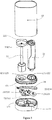
- the said handheld stirrer assembly comprises a handheld portion 21 installed with a drive motor and a control unit, a transmission stirring portion 22 which can be detachably connected to the said handheld portion 21 and transmit the output torque of the handheld portion 21 by virtue of the transmission rod thereof, as well as at least one stirring cutter 23 which can be detachably installed to the transmission rod head of the said transmission stirring portion 22.
- the said handheld portion 21, transmission stirring portion 22 and stirring prop 23 are assembled to be a handheld stirrer 2.
- the said accommodating device 1 comprises an accessory accommodating base 11, an accommodating and supporting partition cover 12 covering the accessory accommodating base, as well as an accommodating main cover with a measuring cup function 13 covering the said accessory accommodating base 11 and the accommodating and supporting partition cover 12.
- the said accommodating main cover with a measuring cup function 13 takes on the shape of an upturned bucket.
- the bucket bottom of the accommodating main cover with a measuring cup function 13 is at the top of the bucket opening, when the accommodating main cover with a measuring cup function 13 is upturned to be the state where the bottom of the bucket is located under the opening of the bucket, the accommodating main cover with a measuring cup function 13 can be served as the measuring cup for placing the substance required to be stirred.
- the said stirring cutter 23 and cutter opener 24 are placed in a space between the said accessory accommodating base 11 and the accommodating and supporting partition cover 12.
- the said handheld portion 21 and transmission stirring portion 22 are supported by the accommodating and supporting partition cover 12, and placed in a space between the accommodating and supporting partition cover 12 and the accommodating main cover with a measuring cup function 13.
- an accessory recesses 111 are processed on the said accessory accommodating base 11 according to the shape of the said stirring cutter 23, such that the said stirring cutter 23 can be caught in the said accessory recesses 111, thus the said stirring cutter 23 is securely positioned and placed.
- shape of the said accessory recesses 111 shall also be designed as the shape matching with that of the cutter opener 24.
- the preferred embodiment of the invention is a concrete implementation proposal implementing the invention based on the situation that the said handheld stirrer assembly further comprises the said cutter opener 24. Therefore, in the preferred embodiment of the invention, considering the shape of the cutter opener 24, the accessory recesses 111 are also designed with a position for positioning and placing the said cutter opener 24.
- a main device recesses 121 are processed on the top of the said accommodating and supporting partition cover 12 according to the head shape of the said handheld portion 21 and the end shape of the transmission stirring portion 22, such that head of the said handheld portion 21 and end of the transmission stirring portion 22 can be caught in the said main device recesses 121.
- end of the said transmission stirring portion 22 is the end opposite to the head end for installing the stirring cutter 23 of the transmission stirring portion 22.
- the said main device recess 121 comprises a handheld recess 122 for positioning and supporting the said handheld portion 21 and a stirring portion recess 123 for positioning and supporting the said transmission stirring portion 22.
- the said handheld recess 122 and stirring portion recess 123 are arranged mutually independent, such that head of the said handheld portion 21 can be caught in the said handheld recess 121 and end of the said transmission stirring portion 22 can be caught in the said stirring portion recess 122.
- the said handheld portion 21 and transmission stirring portion 22 are securely positioned and supported by the said accommodating and supporting partition cover 12.
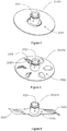
- the preferred embodiment of the invention adopts four stirring cutters 23.
- the said first stirring cutter 23 comprises a flat stirring head 231.
- the flat stirring head 231 comprises a tubular first connector 2311, as well as a circular flat-shaped first stirring head 2312 whose central part is connected to the first connector 2311.
- the said first connector 2311 can be detachably connected to the transmission rod of the said transmission stirring portion 22.
- the said second stirring cutter 23 comprises an inner blade stirring head 232.
- the inner blade stirring head 232 comprises a tubular second connector 2321, as well as a circular flat-shaped second stirring head 2322 whose central part is connected to the second connector 2321.
- At least one through hole 2323 is processed on the flat plate of the second stirring head 2322, edge of each through hole is respectively arranged with a spherical cutting blade 2324, the said cutting blades 2324 cover the through holes 2323 corresponding to the cutting blades 2324 partially.
- the said second connector 2321 can be detachably connected to the transmission rod of the said transmission stirring portion 22.
- the said third stirring cutter 23 comprises a twin-blade stirring head 233.
- the twin-blade stirring head 233 comprises a tubular third connector 2331, as well as a straight strip-shaped third stirring head 2332 whose central part is connected to the third connector 2331. Both ends of the third stirring head 2332 are respectively processed with a cutting blade portion 2333.
- the said third connector 2331 can be detachably connected to the transmission rod of the said transmission stirring portion 22.
- the said fourth stirring cutter 23 comprises a four-blade stirring head 234.
- the four-blade stirring head 234 comprises a tubular fourth connector 2341, as well as a straight strip-shaped fourth stirring head 2342 whose central part is connected to the fourth connector 2341.
- One end of the fourth stirring head 2342 is an upper blade 2343 bent upward, while the other end is a lower blade 2344 bent twice downward whose tool face is parallel to the central part of the said fourth stirring head 2342.
- Central part of the said fourth stirring head 2342 is arranged with two triangular flat-shaped horizontal blades 2345 protruding outwardly.
- the said fourth connector 2341 can be detachably connected to the transmission rod of the said transmission stirring portion 22.
- the said accommodating device 1 further comprises a cutter opener 24 for dismounting the stirring cutter 23 from the said transmission stirring portion 22.
- the said cutter opener 24 is strip shaped, one end of which is processed with a clamping mouth 241 recessed towards the plate inwardly. With the clamping and buckling function of the clamping mouth 241, the said stirring cutter 23 is installed to the transmission rod head of the transmission stirring portion 22, or the said stirring cutter 23 is removed from the transmission rod head of the transmission stirring portion 22.
- the said transmission stirring portion 22 comprises a stirring head cover 221 arranged at the head end of the transmission rod, for covering the stirring cutter 23 which is installed at the said transmission rod head.
- the said stirring head cover 221 comprises a conical surface shaped top cover 2211, as well as a tubular skirt cover 2212 arranged to be connected to the lower edge of larger diameter of the top cover 2211.
- the accommodating device 1 can store a complete set of handheld stirrer assemblies, which are covered, so as to avoid outside dust and reduce number of times of cleaning. Meanwhile, the said main accommodating cover with a measuring cup function 13 can also be served as a measuring cup, achieving multi-purpose usage.
- the invention has not only reduced the cleaning frequency of the handheld stirrer assembly, but has saved water resource.
- the said handheld stirrer assembly is compactly accommodated into the accommodating device through the above accommodating method, such that the whole using process of the handheld stirrer is tidy and convenient.
- the said accommodating main cover with a measuring cup function 13 can not only play the role of a stirring measuring cup, but can avoid dust, achieving dual-purpose usage, thus saving fussy operating steps for users, meanwhile, the compact structure in the accommodating device can save as much space as possible for users.
Landscapes
- Engineering & Computer Science (AREA)
- Mechanical Engineering (AREA)
- Food Science & Technology (AREA)
- Food-Manufacturing Devices (AREA)
- Mixers Of The Rotary Stirring Type (AREA)
Claims (11)
- Produit mélangeur comprenant un ensemble mélangeur portatif comportant un dispositif de réception destiné à recevoir l'ensemble mélangeur portatif,
dans lequel l'ensemble mélangeur portatif comprend une partie portative (21) pourvue d'un moteur d'entraînement et d'une unité de commande, une partie de transmission du mouvement de mélange (22) adaptée à être reliée de façon détachable à la partie portative (21) et à transmettre un couple de sortie à la partie portative (21) par le biais d'une tige de transmission de celle-ci et au moins un couteau de mélange (23) adaptée à être installée de façon détachable sur une tête de la tige de transmission de la partie de transmission du mouvement de mélange (22) ; caractérisé en ce que :le dispositif de réception (1) comprend une base de réception d'accessoire (11) un couvercle de séparation de réception et de support (12) adapté à recouvrir la base de réception d'accessoire et un couvercle principal de réception comportant une fonction de verre doseur (13) adapté à couvrir la base de réception d'accessoire (11) et le couvercle de séparation de réception et de support (12); dans lequel le couvercle principal de réception (13) prend la forme d'un godet ;lorsque l'ensemble mélangeur portatif est réceptionné dans le dispositif de réception (1), le couteau de mélange (23) est placé dans un espace entre la base de réception d'accessoire (11) et le couvercle de séparation de réception et de support (12) ; la partie portative (21) et la partie de transmission du mouvement de mélange (22) sont supportées par le couvercle de séparation de réception et de support (12) et placées dans un espace entre le couvercle de séparation de réception et de support (12) et le couvercle principal de réception. - Produit mélangeur selon la revendication 1, dans lequel
un évidement pour accessoire (111) est formé dans la base de réception d'accessoire (11) selon la forme du couteau de mélange (23), de sorte que le couteau de mélange (23) peut être capturé dans l'évidement pour accessoire (111) et positionné en toute sécurité et placé dans celui-ci. - Produit mélangeur selon la revendication 1, dans lequel
un évidement principal du dispositif (121) est formé dans une partie supérieure du couvercle de séparation de réception et de support (12) selon la forme d'une tête de la partie portative (21) et la forme de l'extrémité de partie de transmission du mouvement de mélange (22), de sorte que la tête de partie portative (21) et l'extrémité de partie de transmission du mouvement de mélange (22) peuvent être capturées dans l'évidement principal du dispositif (121) pour permettre à la partie portative (21) et à la partie de transmission du mouvement de mélange (22) d'être supportées en toute sécurité. - Produit mélangeur selon la revendication 3, dans lequel
l'évidement principal du dispositif (121) comprend un évidement de la partie portative (122) destiné à positionner et à supporter la partie portative (21) et un évidement de la partie de mélange (123) destiné à positionner et à supporter la partie de transmission du mouvement de mélange (22) ; l'évidement de la partie portative (122) et l'évidement de la partie de mélange (123) sont agencées de façon mutuellement indépendante, de sorte qu'une tête de la partie portative (21) peut être capturée dans l'évidement de la partie portative (121) et une extrémité de la partie de transmission du mouvement de mélange (22) peut être capturée dans l'évidement de la partie de mélange (122) pour permettre à la partie portative (21) et à la partie de transmission du mouvement de mélange (22) d'être positionnées et supportées en toute sécurité par le couvercle de séparation de réception et de support (12). - Produit mélangeur selon la revendication 1, dans lequel
le couteau de mélange (23) comprend une tête de mélange plate (231) ; la tête de mélange plate (231) comprend un premier raccordement tubulaire (2311) et une première tête de mélange de forme plate circulaire (2312) comportant une partie centrale reliée au premier raccordement (2311); le premier raccordement (2311) adapté à être relié de façon détachable à la tige de transmission de la partie de transmission du mouvement de mélange (22). - Produit mélangeur selon la revendication 1, dans lequel
le couteau de mélange (23) comprend une tête de mélange à lame interne (232); la tête de mélange à lame interne (232) comprend un deuxième raccordement tubulaire (2321) et une deuxième tête de mélange de forme plate circulaire (2322) dont la partie centrale est reliée au deuxième raccordement (2321) ; au moins un trou traversant (2323) est formé dans la plaque plate de la deuxième tête de mélange (2322), le bord de chaque trou traversant agencé respectivement avec une lame de coupe sphérique (2324); les lames de coupe sphériques (2324) couvrent les trous traversants correspondants (2323) partiellement ; et le deuxième raccordement (2321) est adapté à être relié de façon détachable à la tige de transmission de la partie de transmission du mouvement de mélange (22). - Produit mélangeur selon la revendication 6, dans lequel
le couteau de mélange (23) comprend une tête de mélange à lame double (233) ; la tête de mélange à lame double (233) comprend un troisième raccordement tubulaire (2331) et une troisième tête de mélange en forme de barrette droite (2332) dont la partie centrale est reliée au troisième raccordement (2331); les deux extrémités de la troisième tête de mélange (2332) sont formées respectivement avec une partie lame de coupe (2333) et le troisième raccordement (2331) est adapté à être relié de façon détachable à la tige de transmission de la partie de transmission du mouvement de mélange (22). - Produit mélangeur selon la revendication 1, dans lequel
le couteau de mélange (23) comprend une tête de mélange à quatre lames (234) ; ladite tête de mélange à quatre lames (234) comprend un quatrième raccordement tubulaire (2341) et une quatrième tête de mélange en forme de barrette droite (2342) dont la partie centrale est reliée au quatrième raccordement (2341); une extrémité de la quatrième tête de mélange (2342) est une lame supérieure (2343) courbée vers le haut, tandis que l'autre extrémité est une lame inférieure (2344) courbée deux fois vers le bas dont la face d'outil est parallèle à la partie centrale de la quatrième tête de mélange (2342) ; la partie centrale de la quatrième tête de mélange (2342) est agencée avec deux lames horizontales de forme plate triangulaire (2345) faisant saillie vers l'extérieur et le quatrième raccordement (2341) est adapté à être relié de façon détachable à la tige de transmission de la partie de transmission du mouvement de mélange (22). - Produit mélangeur selon la revendication 1, dans lequel
celui-ci comprend en outre un démonte-lame (24) destiné au montage et au démontage du couteau de mélange (23) à partir de la partie de transmission du mouvement de mélange (22) ; le démonte-lame (24) est en forme de barrette dont une extrémité est pourvue d'une embouchure de serrage (241) en retrait vers la plaque intérieurement ; avec la fonction de verrouillage et de bouclage de l'embouchure de serrage (241), le couteau de mélange (23) est installé sur la tête de la tige de transmission de la partie de transmission du mouvement de mélange (22), ou le couteau de mélange (23) est retiré à partir de la tête de la tige de transmission de la partie de transmission du mouvement de mélange (22). - Produit mélangeur selon la revendication 1, dans lequel
la partie de transmission du mouvement de mélange (22) comprend un couvercle de la tête de mélange (221) agencé à l'extrémité de la tête de la tige de transmission, destinée à couvrir le couteau de mélange (23) qui est installé sur la tête de la tige de transmission ; le couvercle de la tête de mélange (221) comprend un couvercle supérieur en forme de surface conique (2211) et un couvercle de jupe tubulaire (2212) agencé afin d'être relié à un bord inférieur de l'extrémité du couvercle supérieur (2211) de plus grand diamètre. - Procédé d'utilisation du produit mélangeur selon la revendication 1, caractérisé en ce que le procédé comprend les étapes suivantes :A. lorsque le mélangeur portatif doit être utilisé, soulever et tirer vers le bas le couvercle principal de réception comportant la fonction de verre doseur (13) à partir de la base de réception d'accessoire (11) couvrant le couvercle de séparation de réception et de support (12) et retourner le couvercle principal de réception comportant la fonction de verre doseur (13) pour être dans l'état où le fond du godet est situé sous l'ouverture du godet, ainsi, le couvercle principal de réception comportant la fonction de verre doseur (13) sert de verre doseur ;B. infuser la substance nécessaire devant être mélangée dans le couvercle principal de réception retourné vers le haut comportant la fonction de verre doseur (13) qui sert de verre doseur ;C. assembler la partie portative (21) avec la partie de transmission du mouvement de mélange (22) ;D. ouvrir le couvercle de séparation de réception et de support (12), choisir un couteau de mélange (23) et installer le couteau de mélange (23) sur la tête de la tige de transmission de la partie de transmission du mouvement de mélange (22) par le biais du démonte-lame (24) ;E. étendre le mélangeur portatif assemblé dans le couvercle principal de réception comportant une fonction de verre doseur (13) destinée au mélange ;F. lorsque le mélangeur portatif doit être réceptionné après le mélange, déposer le couteau de mélange (23) de la tête de la tige de transmission de la partie de transmission du mouvement de mélange (22) par le biais du démonte-lame (24) ;G. placer le couteau de mélange (23) et le démonte-lame (24) dans la base de réception d'accessoire (11) ; et couvrir la base de réception d'accessoire (11) avec le couvercle de séparation de réception et de support (12) ;H. démonter la partie portative (21) et la partie de transmission du mouvement de mélange (22) et les placer en haut du couvercle de séparation de réception et de support (12) ;I. après le nettoyage du couvercle principal de réception comportant une fonction de verre doseur (13), le renverser pour être dans l'état où le fond du godet est situé sous l'ouverture du godet, de manière à couvrir la partie portative (21) et la partie de transmission du mouvement de mélange (22), ainsi que ledit couvercle de séparation de réception et de support (12) et la base de réception d'accessoire (11).
Applications Claiming Priority (1)
| Application Number | Priority Date | Filing Date | Title |
|---|---|---|---|
| PCT/CN2012/088146 WO2014101241A1 (fr) | 2012-12-31 | 2012-12-31 | Dispositif de réception d'ensemble mélangeur portatif et procédé de réception de celui-ci |
Publications (3)
| Publication Number | Publication Date |
|---|---|
| EP2941987A1 EP2941987A1 (fr) | 2015-11-11 |
| EP2941987A4 EP2941987A4 (fr) | 2016-09-07 |
| EP2941987B1 true EP2941987B1 (fr) | 2018-11-28 |
Family
ID=51019823
Family Applications (1)
| Application Number | Title | Priority Date | Filing Date |
|---|---|---|---|
| EP12890640.1A Not-in-force EP2941987B1 (fr) | 2012-12-31 | 2012-12-31 | Dispositif de réception d'ensemble mélangeur portatif et procédé de réception de celui-ci |
Country Status (3)
| Country | Link |
|---|---|
| EP (1) | EP2941987B1 (fr) |
| RU (1) | RU2603574C1 (fr) |
| WO (1) | WO2014101241A1 (fr) |
Families Citing this family (1)
| Publication number | Priority date | Publication date | Assignee | Title |
|---|---|---|---|---|
| WO2021259251A1 (fr) | 2020-06-23 | 2021-12-30 | Whirlpool Corporation | Panier de stockage pour ensemble robot de cuisine |
Family Cites Families (7)
| Publication number | Priority date | Publication date | Assignee | Title |
|---|---|---|---|---|
| CH568206A5 (fr) * | 1973-02-06 | 1975-10-31 | Rotel Ag | |
| US6068397A (en) * | 1999-04-13 | 2000-05-30 | Revel, Inc. | Folding stand mixer assembly |
| DE20318918U1 (de) * | 2003-12-05 | 2005-04-07 | Lenz Beteiligungs Gmbh & Co Kg | Grillutensiliensatz |
| US20080298164A1 (en) * | 2004-08-09 | 2008-12-04 | Ian Geoffrey Wilson | Cordless Mixer |
| DE102005038919A1 (de) * | 2005-08-17 | 2007-03-15 | BSH Bosch und Siemens Hausgeräte GmbH | Elektromotorisches Küchengerät mit elektrischer oder elektronischer Verriegelung |
| CN101485547B (zh) * | 2008-01-17 | 2013-11-06 | 厦门灿坤实业股份有限公司 | 一种复合式食物调理装置 |
| US8746957B2 (en) * | 2010-01-07 | 2014-06-10 | Hamilton Beach Brands Inc. | Storage case for a hand mixer |
-
2012
- 2012-12-31 EP EP12890640.1A patent/EP2941987B1/fr not_active Not-in-force
- 2012-12-31 WO PCT/CN2012/088146 patent/WO2014101241A1/fr not_active Ceased
- 2012-12-31 RU RU2015131830/12A patent/RU2603574C1/ru active
Non-Patent Citations (1)
| Title |
|---|
| None * |
Also Published As
| Publication number | Publication date |
|---|---|
| EP2941987A1 (fr) | 2015-11-11 |
| WO2014101241A1 (fr) | 2014-07-03 |
| RU2603574C1 (ru) | 2016-11-27 |
| EP2941987A4 (fr) | 2016-09-07 |
Similar Documents
| Publication | Publication Date | Title |
|---|---|---|
| WO2018191960A1 (fr) | Robot de cuisine multifonctionnel | |
| CN203524522U (zh) | 一种具有双钩式揉面钩的多功能揉面机 | |
| EP2941987B1 (fr) | Dispositif de réception d'ensemble mélangeur portatif et procédé de réception de celui-ci | |
| CN221888126U (zh) | 破壁机的清洗装置以及破壁机 | |
| CN215190872U (zh) | 炒菜机的内部搅拌结构和炒菜机 | |
| CN217318105U (zh) | 一种拆装方便的单刀头浮动剃须刀 | |
| CN210019066U (zh) | 一种搅拌组件及搅拌机 | |
| CN203220277U (zh) | 一种省力擦菜器 | |
| CN2330288Y (zh) | 搅拌器 | |
| CN201371459Y (zh) | 一种菜刀 | |
| CN201143732Y (zh) | 组合型电动切割机 | |
| CN220236723U (zh) | 一种新型搅拌机刀具 | |
| CN106691239A (zh) | 包括多个切割工具的食物处理器 | |
| CN205870681U (zh) | 家庭安全环保实用型切菜机 | |
| CN206565175U (zh) | 厨师机 | |
| CN211164170U (zh) | 一种可更换式切蛋器 | |
| CN214631841U (zh) | 一种多功能菜板 | |
| CN204260506U (zh) | 一种榨汁机用杯体 | |
| CN218419239U (zh) | 一种方便自动送菜的厨房用切菜装置 | |
| CN222285318U (zh) | 多功能立式食品加工机 | |
| CN222322738U (zh) | 一种奶昔机 | |
| CN218614312U (zh) | 一种全自动切菜机 | |
| CN102551495A (zh) | 新型果汁机 | |
| CN218452254U (zh) | 一种双刀切菜组件及包括其的盆式碎菜机或和面机 | |
| CN217792701U (zh) | 一种分离式火锅把手结构 |
Legal Events
| Date | Code | Title | Description |
|---|---|---|---|
| PUAI | Public reference made under article 153(3) epc to a published international application that has entered the european phase |
Free format text: ORIGINAL CODE: 0009012 |
|
| 17P | Request for examination filed |
Effective date: 20150725 |
|
| AK | Designated contracting states |
Kind code of ref document: A1 Designated state(s): AL AT BE BG CH CY CZ DE DK EE ES FI FR GB GR HR HU IE IS IT LI LT LU LV MC MK MT NL NO PL PT RO RS SE SI SK SM TR |
|
| AX | Request for extension of the european patent |
Extension state: BA ME |
|
| DAX | Request for extension of the european patent (deleted) | ||
| A4 | Supplementary search report drawn up and despatched |
Effective date: 20160808 |
|
| RIC1 | Information provided on ipc code assigned before grant |
Ipc: A47J 43/07 20060101ALI20160802BHEP Ipc: A47J 43/06 20060101AFI20160802BHEP Ipc: A47J 43/04 20060101ALI20160802BHEP |
|
| GRAP | Despatch of communication of intention to grant a patent |
Free format text: ORIGINAL CODE: EPIDOSNIGR1 |
|
| INTG | Intention to grant announced |
Effective date: 20180619 |
|
| RIN1 | Information on inventor provided before grant (corrected) |
Inventor name: LI, XIAOCHUAN |
|
| GRAS | Grant fee paid |
Free format text: ORIGINAL CODE: EPIDOSNIGR3 |
|
| GRAA | (expected) grant |
Free format text: ORIGINAL CODE: 0009210 |
|
| AK | Designated contracting states |
Kind code of ref document: B1 Designated state(s): AL AT BE BG CH CY CZ DE DK EE ES FI FR GB GR HR HU IE IS IT LI LT LU LV MC MK MT NL NO PL PT RO RS SE SI SK SM TR |
|
| REG | Reference to a national code |
Ref country code: GB Ref legal event code: FG4D |
|
| REG | Reference to a national code |
Ref country code: CH Ref legal event code: EP |
|
| REG | Reference to a national code |
Ref country code: AT Ref legal event code: REF Ref document number: 1069243 Country of ref document: AT Kind code of ref document: T Effective date: 20181215 |
|
| REG | Reference to a national code |
Ref country code: DE Ref legal event code: R096 Ref document number: 602012054215 Country of ref document: DE |
|
| REG | Reference to a national code |
Ref country code: IE Ref legal event code: FG4D |
|
| REG | Reference to a national code |
Ref country code: NL Ref legal event code: MP Effective date: 20181128 |
|
| REG | Reference to a national code |
Ref country code: LT Ref legal event code: MG4D |
|
| REG | Reference to a national code |
Ref country code: AT Ref legal event code: MK05 Ref document number: 1069243 Country of ref document: AT Kind code of ref document: T Effective date: 20181128 |
|
| PG25 | Lapsed in a contracting state [announced via postgrant information from national office to epo] |
Ref country code: FI Free format text: LAPSE BECAUSE OF FAILURE TO SUBMIT A TRANSLATION OF THE DESCRIPTION OR TO PAY THE FEE WITHIN THE PRESCRIBED TIME-LIMIT Effective date: 20181128 Ref country code: IS Free format text: LAPSE BECAUSE OF FAILURE TO SUBMIT A TRANSLATION OF THE DESCRIPTION OR TO PAY THE FEE WITHIN THE PRESCRIBED TIME-LIMIT Effective date: 20190328 Ref country code: LV Free format text: LAPSE BECAUSE OF FAILURE TO SUBMIT A TRANSLATION OF THE DESCRIPTION OR TO PAY THE FEE WITHIN THE PRESCRIBED TIME-LIMIT Effective date: 20181128 Ref country code: AT Free format text: LAPSE BECAUSE OF FAILURE TO SUBMIT A TRANSLATION OF THE DESCRIPTION OR TO PAY THE FEE WITHIN THE PRESCRIBED TIME-LIMIT Effective date: 20181128 Ref country code: NO Free format text: LAPSE BECAUSE OF FAILURE TO SUBMIT A TRANSLATION OF THE DESCRIPTION OR TO PAY THE FEE WITHIN THE PRESCRIBED TIME-LIMIT Effective date: 20190228 Ref country code: LT Free format text: LAPSE BECAUSE OF FAILURE TO SUBMIT A TRANSLATION OF THE DESCRIPTION OR TO PAY THE FEE WITHIN THE PRESCRIBED TIME-LIMIT Effective date: 20181128 Ref country code: HR Free format text: LAPSE BECAUSE OF FAILURE TO SUBMIT A TRANSLATION OF THE DESCRIPTION OR TO PAY THE FEE WITHIN THE PRESCRIBED TIME-LIMIT Effective date: 20181128 Ref country code: ES Free format text: LAPSE BECAUSE OF FAILURE TO SUBMIT A TRANSLATION OF THE DESCRIPTION OR TO PAY THE FEE WITHIN THE PRESCRIBED TIME-LIMIT Effective date: 20181128 Ref country code: BG Free format text: LAPSE BECAUSE OF FAILURE TO SUBMIT A TRANSLATION OF THE DESCRIPTION OR TO PAY THE FEE WITHIN THE PRESCRIBED TIME-LIMIT Effective date: 20190228 |
|
| PG25 | Lapsed in a contracting state [announced via postgrant information from national office to epo] |
Ref country code: PT Free format text: LAPSE BECAUSE OF FAILURE TO SUBMIT A TRANSLATION OF THE DESCRIPTION OR TO PAY THE FEE WITHIN THE PRESCRIBED TIME-LIMIT Effective date: 20190328 Ref country code: AL Free format text: LAPSE BECAUSE OF FAILURE TO SUBMIT A TRANSLATION OF THE DESCRIPTION OR TO PAY THE FEE WITHIN THE PRESCRIBED TIME-LIMIT Effective date: 20181128 Ref country code: SE Free format text: LAPSE BECAUSE OF FAILURE TO SUBMIT A TRANSLATION OF THE DESCRIPTION OR TO PAY THE FEE WITHIN THE PRESCRIBED TIME-LIMIT Effective date: 20181128 Ref country code: RS Free format text: LAPSE BECAUSE OF FAILURE TO SUBMIT A TRANSLATION OF THE DESCRIPTION OR TO PAY THE FEE WITHIN THE PRESCRIBED TIME-LIMIT Effective date: 20181128 Ref country code: GR Free format text: LAPSE BECAUSE OF FAILURE TO SUBMIT A TRANSLATION OF THE DESCRIPTION OR TO PAY THE FEE WITHIN THE PRESCRIBED TIME-LIMIT Effective date: 20190301 |
|
| PG25 | Lapsed in a contracting state [announced via postgrant information from national office to epo] |
Ref country code: NL Free format text: LAPSE BECAUSE OF FAILURE TO SUBMIT A TRANSLATION OF THE DESCRIPTION OR TO PAY THE FEE WITHIN THE PRESCRIBED TIME-LIMIT Effective date: 20181128 |
|
| PG25 | Lapsed in a contracting state [announced via postgrant information from national office to epo] |
Ref country code: IT Free format text: LAPSE BECAUSE OF FAILURE TO SUBMIT A TRANSLATION OF THE DESCRIPTION OR TO PAY THE FEE WITHIN THE PRESCRIBED TIME-LIMIT Effective date: 20181128 Ref country code: CZ Free format text: LAPSE BECAUSE OF FAILURE TO SUBMIT A TRANSLATION OF THE DESCRIPTION OR TO PAY THE FEE WITHIN THE PRESCRIBED TIME-LIMIT Effective date: 20181128 Ref country code: PL Free format text: LAPSE BECAUSE OF FAILURE TO SUBMIT A TRANSLATION OF THE DESCRIPTION OR TO PAY THE FEE WITHIN THE PRESCRIBED TIME-LIMIT Effective date: 20181128 Ref country code: DK Free format text: LAPSE BECAUSE OF FAILURE TO SUBMIT A TRANSLATION OF THE DESCRIPTION OR TO PAY THE FEE WITHIN THE PRESCRIBED TIME-LIMIT Effective date: 20181128 |
|
| REG | Reference to a national code |
Ref country code: DE Ref legal event code: R097 Ref document number: 602012054215 Country of ref document: DE |
|
| PG25 | Lapsed in a contracting state [announced via postgrant information from national office to epo] |
Ref country code: EE Free format text: LAPSE BECAUSE OF FAILURE TO SUBMIT A TRANSLATION OF THE DESCRIPTION OR TO PAY THE FEE WITHIN THE PRESCRIBED TIME-LIMIT Effective date: 20181128 Ref country code: LU Free format text: LAPSE BECAUSE OF NON-PAYMENT OF DUE FEES Effective date: 20181231 Ref country code: SM Free format text: LAPSE BECAUSE OF FAILURE TO SUBMIT A TRANSLATION OF THE DESCRIPTION OR TO PAY THE FEE WITHIN THE PRESCRIBED TIME-LIMIT Effective date: 20181128 Ref country code: SK Free format text: LAPSE BECAUSE OF FAILURE TO SUBMIT A TRANSLATION OF THE DESCRIPTION OR TO PAY THE FEE WITHIN THE PRESCRIBED TIME-LIMIT Effective date: 20181128 Ref country code: RO Free format text: LAPSE BECAUSE OF FAILURE TO SUBMIT A TRANSLATION OF THE DESCRIPTION OR TO PAY THE FEE WITHIN THE PRESCRIBED TIME-LIMIT Effective date: 20181128 Ref country code: MC Free format text: LAPSE BECAUSE OF FAILURE TO SUBMIT A TRANSLATION OF THE DESCRIPTION OR TO PAY THE FEE WITHIN THE PRESCRIBED TIME-LIMIT Effective date: 20181128 |
|
| REG | Reference to a national code |
Ref country code: BE Ref legal event code: MM Effective date: 20181231 Ref country code: IE Ref legal event code: MM4A |
|
| PLBE | No opposition filed within time limit |
Free format text: ORIGINAL CODE: 0009261 |
|
| STAA | Information on the status of an ep patent application or granted ep patent |
Free format text: STATUS: NO OPPOSITION FILED WITHIN TIME LIMIT |
|
| PG25 | Lapsed in a contracting state [announced via postgrant information from national office to epo] |
Ref country code: SI Free format text: LAPSE BECAUSE OF FAILURE TO SUBMIT A TRANSLATION OF THE DESCRIPTION OR TO PAY THE FEE WITHIN THE PRESCRIBED TIME-LIMIT Effective date: 20181128 Ref country code: IE Free format text: LAPSE BECAUSE OF NON-PAYMENT OF DUE FEES Effective date: 20181231 |
|
| 26N | No opposition filed |
Effective date: 20190829 |
|
| PG25 | Lapsed in a contracting state [announced via postgrant information from national office to epo] |
Ref country code: BE Free format text: LAPSE BECAUSE OF NON-PAYMENT OF DUE FEES Effective date: 20181231 |
|
| PG25 | Lapsed in a contracting state [announced via postgrant information from national office to epo] |
Ref country code: MT Free format text: LAPSE BECAUSE OF NON-PAYMENT OF DUE FEES Effective date: 20181231 |
|
| PG25 | Lapsed in a contracting state [announced via postgrant information from national office to epo] |
Ref country code: TR Free format text: LAPSE BECAUSE OF FAILURE TO SUBMIT A TRANSLATION OF THE DESCRIPTION OR TO PAY THE FEE WITHIN THE PRESCRIBED TIME-LIMIT Effective date: 20181128 |
|
| PG25 | Lapsed in a contracting state [announced via postgrant information from national office to epo] |
Ref country code: HU Free format text: LAPSE BECAUSE OF FAILURE TO SUBMIT A TRANSLATION OF THE DESCRIPTION OR TO PAY THE FEE WITHIN THE PRESCRIBED TIME-LIMIT; INVALID AB INITIO Effective date: 20121231 Ref country code: CY Free format text: LAPSE BECAUSE OF FAILURE TO SUBMIT A TRANSLATION OF THE DESCRIPTION OR TO PAY THE FEE WITHIN THE PRESCRIBED TIME-LIMIT Effective date: 20181128 Ref country code: MK Free format text: LAPSE BECAUSE OF NON-PAYMENT OF DUE FEES Effective date: 20181128 |
|
| PGFP | Annual fee paid to national office [announced via postgrant information from national office to epo] |
Ref country code: GB Payment date: 20201229 Year of fee payment: 9 Ref country code: FR Payment date: 20201229 Year of fee payment: 9 |
|
| PGFP | Annual fee paid to national office [announced via postgrant information from national office to epo] |
Ref country code: CH Payment date: 20210104 Year of fee payment: 9 |
|
| PGFP | Annual fee paid to national office [announced via postgrant information from national office to epo] |
Ref country code: DE Payment date: 20201229 Year of fee payment: 9 |
|
| REG | Reference to a national code |
Ref country code: DE Ref legal event code: R119 Ref document number: 602012054215 Country of ref document: DE |
|
| REG | Reference to a national code |
Ref country code: CH Ref legal event code: PL |
|
| GBPC | Gb: european patent ceased through non-payment of renewal fee |
Effective date: 20211231 |
|
| PG25 | Lapsed in a contracting state [announced via postgrant information from national office to epo] |
Ref country code: GB Free format text: LAPSE BECAUSE OF NON-PAYMENT OF DUE FEES Effective date: 20211231 Ref country code: DE Free format text: LAPSE BECAUSE OF NON-PAYMENT OF DUE FEES Effective date: 20220701 |
|
| PG25 | Lapsed in a contracting state [announced via postgrant information from national office to epo] |
Ref country code: FR Free format text: LAPSE BECAUSE OF NON-PAYMENT OF DUE FEES Effective date: 20211231 |
|
| PG25 | Lapsed in a contracting state [announced via postgrant information from national office to epo] |
Ref country code: LI Free format text: LAPSE BECAUSE OF NON-PAYMENT OF DUE FEES Effective date: 20211231 Ref country code: CH Free format text: LAPSE BECAUSE OF NON-PAYMENT OF DUE FEES Effective date: 20211231 |