EP2942222A1 - Agencement d'échangeur thermique pour une unité d'entraînement d'une machine agricole - Google Patents
Agencement d'échangeur thermique pour une unité d'entraînement d'une machine agricole Download PDFInfo
- Publication number
- EP2942222A1 EP2942222A1 EP15157993.5A EP15157993A EP2942222A1 EP 2942222 A1 EP2942222 A1 EP 2942222A1 EP 15157993 A EP15157993 A EP 15157993A EP 2942222 A1 EP2942222 A1 EP 2942222A1
- Authority
- EP
- European Patent Office
- Prior art keywords
- heat exchanger
- cooling air
- cooling
- air guide
- arrangement according
- Prior art date
- Legal status (The legal status is an assumption and is not a legal conclusion. Google has not performed a legal analysis and makes no representation as to the accuracy of the status listed.)
- Ceased
Links
- 238000001816 cooling Methods 0.000 claims abstract description 92
- 238000003306 harvesting Methods 0.000 claims abstract 2
- 238000002485 combustion reaction Methods 0.000 claims description 11
- 230000005540 biological transmission Effects 0.000 claims description 7
- 239000000498 cooling water Substances 0.000 claims description 5
- 239000010720 hydraulic oil Substances 0.000 claims description 5
- 239000003921 oil Substances 0.000 claims description 4
- 239000010705 motor oil Substances 0.000 claims description 3
- 241001124569 Lycaenidae Species 0.000 description 2
- 230000001419 dependent effect Effects 0.000 description 2
- 230000002706 hydrostatic effect Effects 0.000 description 2
- 238000010276 construction Methods 0.000 description 1
- 230000001276 controlling effect Effects 0.000 description 1
- 239000002826 coolant Substances 0.000 description 1
- 230000000694 effects Effects 0.000 description 1
- 239000004459 forage Substances 0.000 description 1
- 238000009434 installation Methods 0.000 description 1
- 238000013021 overheating Methods 0.000 description 1
- 238000005057 refrigeration Methods 0.000 description 1
- 230000001105 regulatory effect Effects 0.000 description 1
- 238000011144 upstream manufacturing Methods 0.000 description 1
Images
Classifications
-
- B—PERFORMING OPERATIONS; TRANSPORTING
- B60—VEHICLES IN GENERAL
- B60K—ARRANGEMENT OR MOUNTING OF PROPULSION UNITS OR OF TRANSMISSIONS IN VEHICLES; ARRANGEMENT OR MOUNTING OF PLURAL DIVERSE PRIME-MOVERS IN VEHICLES; AUXILIARY DRIVES FOR VEHICLES; INSTRUMENTATION OR DASHBOARDS FOR VEHICLES; ARRANGEMENTS IN CONNECTION WITH COOLING, AIR INTAKE, GAS EXHAUST OR FUEL SUPPLY OF PROPULSION UNITS IN VEHICLES
- B60K11/00—Arrangement in connection with cooling of propulsion units
- B60K11/08—Air inlets for cooling; Shutters or blinds therefor
- B60K11/085—Air inlets for cooling; Shutters or blinds therefor with adjustable shutters or blinds
-
- F—MECHANICAL ENGINEERING; LIGHTING; HEATING; WEAPONS; BLASTING
- F01—MACHINES OR ENGINES IN GENERAL; ENGINE PLANTS IN GENERAL; STEAM ENGINES
- F01P—COOLING OF MACHINES OR ENGINES IN GENERAL; COOLING OF INTERNAL-COMBUSTION ENGINES
- F01P7/00—Controlling of coolant flow
- F01P7/02—Controlling of coolant flow the coolant being cooling-air
- F01P7/10—Controlling of coolant flow the coolant being cooling-air by throttling amount of air flowing through liquid-to-air heat exchangers
- F01P7/12—Controlling of coolant flow the coolant being cooling-air by throttling amount of air flowing through liquid-to-air heat exchangers by thermostatic control
-
- F—MECHANICAL ENGINEERING; LIGHTING; HEATING; WEAPONS; BLASTING
- F02—COMBUSTION ENGINES; HOT-GAS OR COMBUSTION-PRODUCT ENGINE PLANTS
- F02B—INTERNAL-COMBUSTION PISTON ENGINES; COMBUSTION ENGINES IN GENERAL
- F02B29/00—Engines characterised by provision for charging or scavenging not provided for in groups F02B25/00, F02B27/00 or F02B33/00 - F02B39/00; Details thereof
- F02B29/04—Cooling of air intake supply
- F02B29/0406—Layout of the intake air cooling or coolant circuit
- F02B29/0425—Air cooled heat exchangers
- F02B29/0431—Details or means to guide the ambient air to the heat exchanger, e.g. having a fan, flaps, a bypass or a special location in the engine compartment
-
- F—MECHANICAL ENGINEERING; LIGHTING; HEATING; WEAPONS; BLASTING
- F02—COMBUSTION ENGINES; HOT-GAS OR COMBUSTION-PRODUCT ENGINE PLANTS
- F02B—INTERNAL-COMBUSTION PISTON ENGINES; COMBUSTION ENGINES IN GENERAL
- F02B29/00—Engines characterised by provision for charging or scavenging not provided for in groups F02B25/00, F02B27/00 or F02B33/00 - F02B39/00; Details thereof
- F02B29/04—Cooling of air intake supply
- F02B29/045—Constructional details of the heat exchangers, e.g. pipes, plates, ribs, insulation, materials, or manufacturing and assembly
- F02B29/0456—Air cooled heat exchangers
-
- F—MECHANICAL ENGINEERING; LIGHTING; HEATING; WEAPONS; BLASTING
- F02—COMBUSTION ENGINES; HOT-GAS OR COMBUSTION-PRODUCT ENGINE PLANTS
- F02B—INTERNAL-COMBUSTION PISTON ENGINES; COMBUSTION ENGINES IN GENERAL
- F02B29/00—Engines characterised by provision for charging or scavenging not provided for in groups F02B25/00, F02B27/00 or F02B33/00 - F02B39/00; Details thereof
- F02B29/04—Cooling of air intake supply
- F02B29/0493—Controlling the air charge temperature
-
- B—PERFORMING OPERATIONS; TRANSPORTING
- B60—VEHICLES IN GENERAL
- B60Y—INDEXING SCHEME RELATING TO ASPECTS CROSS-CUTTING VEHICLE TECHNOLOGY
- B60Y2200/00—Type of vehicle
- B60Y2200/20—Off-Road Vehicles
- B60Y2200/22—Agricultural vehicles
- B60Y2200/221—Tractors
-
- F—MECHANICAL ENGINEERING; LIGHTING; HEATING; WEAPONS; BLASTING
- F01—MACHINES OR ENGINES IN GENERAL; ENGINE PLANTS IN GENERAL; STEAM ENGINES
- F01P—COOLING OF MACHINES OR ENGINES IN GENERAL; COOLING OF INTERNAL-COMBUSTION ENGINES
- F01P3/00—Liquid cooling
- F01P3/18—Arrangements or mounting of liquid-to-air heat-exchangers
- F01P2003/187—Arrangements or mounting of liquid-to-air heat-exchangers arranged in series
-
- Y—GENERAL TAGGING OF NEW TECHNOLOGICAL DEVELOPMENTS; GENERAL TAGGING OF CROSS-SECTIONAL TECHNOLOGIES SPANNING OVER SEVERAL SECTIONS OF THE IPC; TECHNICAL SUBJECTS COVERED BY FORMER USPC CROSS-REFERENCE ART COLLECTIONS [XRACs] AND DIGESTS
- Y02—TECHNOLOGIES OR APPLICATIONS FOR MITIGATION OR ADAPTATION AGAINST CLIMATE CHANGE
- Y02T—CLIMATE CHANGE MITIGATION TECHNOLOGIES RELATED TO TRANSPORTATION
- Y02T10/00—Road transport of goods or passengers
- Y02T10/10—Internal combustion engine [ICE] based vehicles
- Y02T10/12—Improving ICE efficiencies
-
- Y—GENERAL TAGGING OF NEW TECHNOLOGICAL DEVELOPMENTS; GENERAL TAGGING OF CROSS-SECTIONAL TECHNOLOGIES SPANNING OVER SEVERAL SECTIONS OF THE IPC; TECHNICAL SUBJECTS COVERED BY FORMER USPC CROSS-REFERENCE ART COLLECTIONS [XRACs] AND DIGESTS
- Y02—TECHNOLOGIES OR APPLICATIONS FOR MITIGATION OR ADAPTATION AGAINST CLIMATE CHANGE
- Y02T—CLIMATE CHANGE MITIGATION TECHNOLOGIES RELATED TO TRANSPORTATION
- Y02T10/00—Road transport of goods or passengers
- Y02T10/80—Technologies aiming to reduce greenhouse gasses emissions common to all road transportation technologies
- Y02T10/88—Optimized components or subsystems, e.g. lighting, actively controlled glasses
Definitions
- the invention relates to a heat exchanger arrangement for a drive unit of an agricultural working machine, in particular a tractor or a self-propelled harvester, with at least two directly juxtaposed, can be acted upon in parallel with a cooling air flow heat exchangers and at least one cooling air blower for generating a cooling air flow.
- corresponding drive units which are provided with a heat exchanger assembly
- a heat exchanger assembly it is in particular an internal combustion engine, wherein the heat exchangers are provided for example for cooling the cooling water or the charge air.
- components of corresponding drive units may be a mechanical or hydromechanical transmission and / or a hydrostatic drive system and / or a working hydraulics. In these cases, for example, a cooling of the transmission or hydraulic oil.
- part of the heat exchanger assembly may be a heat exchanger of an air conditioner.
- Agricultural work machines such as tractors, self-propelled harvesters, in particular combines, forage harvesters and the like, are usually equipped with a complex refrigeration system, since on board an agricultural work machine usually different operating and auxiliary equipment (e.g., engine coolant, charge air, transmission oil, hydraulic oil) are to be cooled.
- operating and auxiliary equipment e.g., engine coolant, charge air, transmission oil, hydraulic oil
- the cooling units of agricultural machines are combined coolers, ie several media are cooled at the same time. Accordingly, the cooling air flow of a single cooling air blower, a plurality of heat exchangers are applied, which are arranged for this purpose, for example, next to or behind each other.
- WO 2008/080305 A1 Reference should be made in this context by way of example WO 2008/080305 A1 ,
- the present invention has for its object to provide a heat exchanger assembly of the type mentioned, which has a reduced power requirement when required cooling of the heat exchanger.
- a heat exchanger assembly according to the features of claim 1. This is characterized in that relative to the direction of the cooling air flow in front of or behind each of the heat exchanger in each case an adjustable, the cooling air flow influencing air guide is arranged.
- heat exchangers are to be provided for different units and their parts. This may be in addition to the usual cooling water cooler and a charge air cooler of the internal combustion engine to cooler for a working hydraulics, for a hydrostatic or hydrodynamic drive and for a transmission and optionally a heat exchanger for an air conditioner.
- the corresponding heat exchangers or coolers are advantageously combined to form a block, that is to say preferably arranged in a frame.
- the air mass flow can be variably, in particular on demand and individually, split on the heat exchanger.
- the air guide elements of the heat exchanger with the highest cooling demand can be set, for example, to an opening cross section, which allows for this a high air mass flow, while heat exchangers with relatively low cooling demand, the associated air guide is set to a small opening cross-section.
- the flow rate on the warmest heat exchanger - at the same speed of the cooling air blower - continues to increase. This possibility of adjustment, the heat exchanger assembly has an increased energy efficiency.
- a flow cross section of the air guide elements should be infinitely adjustable.
- the corresponding cooling air requirement can be determined at each of the heat exchanger, which serves as a parameter for the air allocation and causes a change in the flow cross-section.
- the adjustment takes place continuously.
- an adjustment of the air guide elements can take place in several stages.
- the air guide elements of the individual heat exchangers are adjustable separately from each other. As a result, the air mass flow of a plurality of heat exchangers can be reduced and, in addition, fed to a heat exchanger, so that the flow velocity increases there and thus the heat can be dissipated to the required extent.
- the air guide elements are preferably designed as lamellae, which can each perform a pivoting movement between a maximum opening degree and a closed position.
- the individual air guide elements are adjustable depending on the cooling air requirement of each associated heat exchanger according to an advantageous development.
- the air guide elements each have an adjustment provided preferably electrical adjustment devices.
- the cooling air requirement of the respective heat exchanger is determined by a temperature sensor and a corresponding actual value transmitted to a Regeleitechnisch which controls the adjustment of the respective heat exchanger due to this actual value to set the air mass flow separately to the air mass flow of the other heat exchangers, which are also provided with adjusting ,
- the heat exchangers should be assigned a common cooling air blower. This can be arranged behind or in front of the heat exchangers in accordance with the previously stated arrangement of the air guide elements, viewed in the direction of the cooling air flow. Alternatively, it is possible to provide a plurality of cooling air blower, each associated with one or more heat exchangers. In both cases, the cooling air blowers are controlled as needed, that is, they are switched on or off and / or regulated in terms of their speed.
- an adjustment of the air guide elements and an adjustment of at least one drive of the at least one cooling air blower are connected to a control device, the speed of the at least one cooling air blower depending on the total cooling air requirement and the respective position of the air guide elements in dependence Cooling air requirement of this assigned heat exchanger adjusts.
- the air guide elements will be set to their largest flow cross section. If there is a lesser need for cooling air at individual heat exchangers, then the flow cross-section is throttled to this by means of the air guide elements. At the same time, the fan speed can be lowered. As a result, the total transferred to the at least one fan drive drive power can be reduced. Consequently, the heat exchanger assembly is operated with greater energy efficiency.
- control device is operable to increase a flow cross-section of that air guide element to a maximum value, whose associated heat exchanger has the highest cooling air requirement.
- control device is operable to reduce a flow cross-section of an air guide element to a lower maximum value (i.e., below the maximum lying value) if the heat exchanger associated with this air guide element has a smaller cooling air requirement than can be caused by the cooling air flow.
- the individual combined into a block heat exchanger for cooling the cooling water of an internal combustion engine and / or for cooling of a charge of an exhaust gas turbocharger charge air of the internal combustion engine and / or for cooling the engine oil of the internal combustion engine and / or for cooling a transmission oil and / or for cooling a Hydraulic oil be provided.
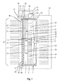
- 1 denotes a heat exchanger arrangement which has three heat exchangers 2, 3 and 4, which are arranged next to one another and thus are acted upon in parallel by a cooling air flow 5.
- the heat exchangers 2, 3 and 4 are enclosed by a frame-like frame 6, which can be fastened in a frame or block, not shown in detail in the figure also not shown agricultural or construction work machine.
- the heat exchanger assembly 1 and thus all heat exchangers 2, 3 and 4 is associated with acting as a suction fan cooling air fan 7, which - is arranged behind the heat exchanger assembly 1 in the flow direction of the aforementioned cooling air flow 5 and thus promotes this through the heat exchangers 2, 3 and 4.
- the cooling air blower 7 is driven by an electric fan motor 8 and has fan blades 9.
- a hydraulic fan motor 8 can also be used.
- a belt drive can be provided by means of which the cooling air fan 7 is driven by a controllable in its output speed clutch.
- part of the heat exchanger assembly 1 air guide elements 10, 11, and 12.
- the air guide element 10 is arranged in front of the heat exchanger 2, the air guide 11 in front of the heat exchanger 3 and the air guide 12 in front of the heat exchanger 4.
- the air guide elements 10, 11 and 12 each have between an open position and a closed position pivotable fins 13, which may be formed substantially identical.
- a flow cross section of the air guide elements 10, 11, 12 can be adjusted continuously depending on their position.
- This adjustment of the spoiler elements 10, 11 and 12 is carried out separately from each other, including the spoiler 10 an adjusting device 14 with an adjusting motor 15, the air guide 11 an adjusting 16 with an adjusting motor 17 and the air guide 13 an adjusting device 18 are associated with an adjusting 19.
- adjusting motors 15, 17 and 19, which perform a linear adjusting movement go out rods 20, 21 and 22, which engage the respective fins 13 of the air guide elements 10, 11 and 12 and these, as indicated, pivot.
- these could be designed as a fixed grid and a slide grate displaceable thereto.
- the heat exchanger assembly 1 a control device 23 which is connected via signal lines 24, 25 and 26 with temperature sensors 27, 28 and 29. These temperature sensors 27, 28 and 29 are each provided for detecting the temperatures of the heat exchangers 2, 3 and 4.
- the control device 23 encoder lines 30, 31, 32 and 33 go from the control device 23 encoder lines 30, 31, 32 and 33, to the Adjustment motors 15, 17 and 19 and are connected to the fan motor 8. Consequently, the control device 23, depending on the temperatures of the heat exchangers 2, 3 and 4 whose air guide elements 10, 11 and 12 are adjusted individually.
- the fan speed of the cooling air blower 7 is specified by the control device 23.
- the control device 23 is a speed of the cooling air blower 7 depending on the total cooling air requirement and the control device 23 sets a respective position of the air guide elements 10, 11, 12 in dependence on the cooling air requirement of the associated heat exchanger 2, 3, 4 a.
- the control device 23 is advantageously operable to increase a flow cross section of that air guide element 10, 11, 12 to a maximum value, whose associated heat exchanger 2, 3, 4 has the highest cooling air requirement.
- the control device is operable to reduce a flow cross-section of an air guide element 10, 11, 12 to a lower maximum value, if the this air guide element 10, 11, 12 associated heat exchanger 2, 3, 4 has a less than by the cooling air flow 5 effected cooling air requirement.
- the air guide 10 of the heat exchanger 2 is almost closed, the air guide 11 of the heat exchanger 3 is completely open and the air guide 12 of the heat exchanger 4 about half open.
- the groups of arrows 34, 35 and 36 shown on the outlet side of the heat exchanger arrangement 1 make it clear which flow rate and thus which air mass flow the individual heat exchangers 2, 3 and 4 are subjected to. Superior to the individual air mass flows of the entire air mass flow through the previously described adjustment of the fan motor 8 egg ngestel It.
- the heat exchanger arrangement according to the invention has the advantage that the power absorbed by the cooling air fan 7 can be reduced overall.
- the demand-dependent adjustment of the air guiding elements 10, 11 and 12 can also be used, in order to achieve a required operating temperature in individual heat exchangers 2, 3 and 4 for the corresponding medium.
Landscapes
- Engineering & Computer Science (AREA)
- Chemical & Material Sciences (AREA)
- Combustion & Propulsion (AREA)
- Mechanical Engineering (AREA)
- General Engineering & Computer Science (AREA)
- Physics & Mathematics (AREA)
- Thermal Sciences (AREA)
- Transportation (AREA)
- Cooling, Air Intake And Gas Exhaust, And Fuel Tank Arrangements In Propulsion Units (AREA)
Applications Claiming Priority (1)
| Application Number | Priority Date | Filing Date | Title |
|---|---|---|---|
| DE102014106253.1A DE102014106253A1 (de) | 2014-05-06 | 2014-05-06 | Wärmetauscheranordnung für eine Antriebseinheit einer landwirschaftlichen Arbeitsmaschine |
Publications (1)
| Publication Number | Publication Date |
|---|---|
| EP2942222A1 true EP2942222A1 (fr) | 2015-11-11 |
Family
ID=52630250
Family Applications (1)
| Application Number | Title | Priority Date | Filing Date |
|---|---|---|---|
| EP15157993.5A Ceased EP2942222A1 (fr) | 2014-05-06 | 2015-03-06 | Agencement d'échangeur thermique pour une unité d'entraînement d'une machine agricole |
Country Status (2)
| Country | Link |
|---|---|
| EP (1) | EP2942222A1 (fr) |
| DE (1) | DE102014106253A1 (fr) |
Cited By (2)
| Publication number | Priority date | Publication date | Assignee | Title |
|---|---|---|---|---|
| EP3235671A1 (fr) * | 2016-04-19 | 2017-10-25 | Batz, S.Coop. | Dispositif d'obturation pour une calandre d'un véhicule |
| FR3093304A1 (fr) * | 2019-02-28 | 2020-09-04 | Valeo Systemes Thermiques | Systeme de regulation thermique destine a un vehicule automobile |
Families Citing this family (1)
| Publication number | Priority date | Publication date | Assignee | Title |
|---|---|---|---|---|
| US9827847B1 (en) * | 2016-07-27 | 2017-11-28 | GM Global Technology Operations LLC | Cooling module airflow distribution control using aero shutter system |
Citations (7)
| Publication number | Priority date | Publication date | Assignee | Title |
|---|---|---|---|---|
| US5566745A (en) * | 1993-05-10 | 1996-10-22 | General Electric Company | Shuttered radiator system with control |
| DE202007005860U1 (de) * | 2007-04-21 | 2008-08-21 | Liebherr-Werk Bischofshofen Ges.M.B.H. | Kühleranlage |
| US20110246023A1 (en) * | 2010-04-01 | 2011-10-06 | Gm Global Technoloy Operations, Inc. | Powertrain Thermal Control with Grille Airflow Shutters |
| US20110308763A1 (en) * | 2010-06-17 | 2011-12-22 | Gm Global Technology Operations, Inc. | Fuel efficient powertrain cooling systems and radiator modules |
| DE102011080777A1 (de) * | 2010-12-03 | 2012-06-06 | Hyundai Motor Co. | Vorrichtung zum einstellen einer durchflussmenge für ein fahrzeug und kühleinrichtung fur ein hybridfahrzeug unter verwendung derselben |
| DE102011089035A1 (de) * | 2011-12-19 | 2013-06-20 | Bayerische Motoren Werke Aktiengesellschaft | Steuerung verstellbarer Kühlluftklappen eines Kraftfahrzeugs mit einem einen Lader umfassenden Verbrennungsmotor |
| US20130284419A1 (en) * | 2012-04-27 | 2013-10-31 | Cnh America Llc | Combine cooling control system |
Family Cites Families (1)
| Publication number | Priority date | Publication date | Assignee | Title |
|---|---|---|---|---|
| CN101209669B (zh) | 2006-12-30 | 2012-05-16 | 卡特彼勒公司 | 具有策略性排列的换热器列的冷却系统 |
-
2014
- 2014-05-06 DE DE102014106253.1A patent/DE102014106253A1/de not_active Withdrawn
-
2015
- 2015-03-06 EP EP15157993.5A patent/EP2942222A1/fr not_active Ceased
Patent Citations (7)
| Publication number | Priority date | Publication date | Assignee | Title |
|---|---|---|---|---|
| US5566745A (en) * | 1993-05-10 | 1996-10-22 | General Electric Company | Shuttered radiator system with control |
| DE202007005860U1 (de) * | 2007-04-21 | 2008-08-21 | Liebherr-Werk Bischofshofen Ges.M.B.H. | Kühleranlage |
| US20110246023A1 (en) * | 2010-04-01 | 2011-10-06 | Gm Global Technoloy Operations, Inc. | Powertrain Thermal Control with Grille Airflow Shutters |
| US20110308763A1 (en) * | 2010-06-17 | 2011-12-22 | Gm Global Technology Operations, Inc. | Fuel efficient powertrain cooling systems and radiator modules |
| DE102011080777A1 (de) * | 2010-12-03 | 2012-06-06 | Hyundai Motor Co. | Vorrichtung zum einstellen einer durchflussmenge für ein fahrzeug und kühleinrichtung fur ein hybridfahrzeug unter verwendung derselben |
| DE102011089035A1 (de) * | 2011-12-19 | 2013-06-20 | Bayerische Motoren Werke Aktiengesellschaft | Steuerung verstellbarer Kühlluftklappen eines Kraftfahrzeugs mit einem einen Lader umfassenden Verbrennungsmotor |
| US20130284419A1 (en) * | 2012-04-27 | 2013-10-31 | Cnh America Llc | Combine cooling control system |
Cited By (3)
| Publication number | Priority date | Publication date | Assignee | Title |
|---|---|---|---|---|
| EP3235671A1 (fr) * | 2016-04-19 | 2017-10-25 | Batz, S.Coop. | Dispositif d'obturation pour une calandre d'un véhicule |
| US10166858B2 (en) | 2016-04-19 | 2019-01-01 | Batz, S.Coop. | Shutter device for a front grille of a vehicle |
| FR3093304A1 (fr) * | 2019-02-28 | 2020-09-04 | Valeo Systemes Thermiques | Systeme de regulation thermique destine a un vehicule automobile |
Also Published As
| Publication number | Publication date |
|---|---|
| DE102014106253A1 (de) | 2015-11-12 |
Similar Documents
| Publication | Publication Date | Title |
|---|---|---|
| DE4327261C1 (de) | Kühlmittelkreislauf | |
| EP1444441A1 (fr) | Procede de maintien a la temperature voulue d'une pompe a vide a vis | |
| DE102004024289A1 (de) | Kühlsystem für ein Fahrzeug | |
| DE102013113489A1 (de) | Verschließbare Luftleiteinrichtung an einem Fahrzeug | |
| DE102014008749A1 (de) | Bodenfräsmaschine mit kühlsystem, kühlsystem und verfahren zur kühlung einer bodenfräsmaschine | |
| DE3136673A1 (de) | Stark aufgeladene und mit luftkuehlungssystem ausgestattete brennkraftmaschine sowie kuehlungssystem fuer derartige brennkraftmaschinen | |
| DE102013220039A1 (de) | Wärmeübertrager | |
| EP2562379A1 (fr) | Circuit d'agent réfrigérant | |
| DE102018115671A1 (de) | Aktive Unterbodenanordnung für ein Fahrzeug | |
| EP1884635A2 (fr) | Dispositif d'entraînement pour un véhicule utilitaire industriel ou agricole et procédé de fonctionnement d'un dispositif d'entraînement | |
| EP2942222A1 (fr) | Agencement d'échangeur thermique pour une unité d'entraînement d'une machine agricole | |
| EP3460294B1 (fr) | Transmission à refroidissement par l'huile | |
| DE102012011227A1 (de) | Verbrennungskraftmaschine für einen Kraftwagen | |
| DE102010031835A1 (de) | Lüfterregelung | |
| DE102013201789A1 (de) | Kühlsystem für einen Fahrzeugantrieb | |
| EP2562378B1 (fr) | Stratégie de fonctionnement d'un circuit d'agent réfrigérant séparé | |
| EP3320197B1 (fr) | Circuit à fluide de refroidissement pour boîte de vitesses à refroidissement par liquide | |
| EP2431702A2 (fr) | Machine électrique refroidi par air et procéde pour actionner une telle machine | |
| DE102013225610A1 (de) | Luftklappenvorrichtung | |
| DE1214936B (de) | Kuehleinrichtung fuer Fahrzeugbrennkraft-maschinen | |
| EP3009629B1 (fr) | Procédé et dispositif de réglage d'une pression de charge dans un moteur à combustion avec un compresseur à ondes de pression | |
| DE102008041800B4 (de) | Kühleinrichtung für ein Kraftfahrzeug | |
| DE102022205803A1 (de) | Zusatz-Wärmetauscheinheit für ein Leistungsaggregat eines Kraftfahrzeugs | |
| EP2789825B1 (fr) | Moissonneuse | |
| EP2602449B1 (fr) | Moteur à combustion interne avec turbosoufflante de gaz d'échappement et refroidisseur de gaz d'échappement ainsi que procédé de commande/réglage de la température de fonctionnement de la turbosoufflante de gaz d'échappement |
Legal Events
| Date | Code | Title | Description |
|---|---|---|---|
| PUAI | Public reference made under article 153(3) epc to a published international application that has entered the european phase |
Free format text: ORIGINAL CODE: 0009012 |
|
| AK | Designated contracting states |
Kind code of ref document: A1 Designated state(s): AL AT BE BG CH CY CZ DE DK EE ES FI FR GB GR HR HU IE IS IT LI LT LU LV MC MK MT NL NO PL PT RO RS SE SI SK SM TR |
|
| AX | Request for extension of the european patent |
Extension state: BA ME |
|
| 17P | Request for examination filed |
Effective date: 20160511 |
|
| RBV | Designated contracting states (corrected) |
Designated state(s): AL AT BE BG CH CY CZ DE DK EE ES FI FR GB GR HR HU IE IS IT LI LT LU LV MC MK MT NL NO PL PT RO RS SE SI SK SM TR |
|
| RAP1 | Party data changed (applicant data changed or rights of an application transferred) |
Owner name: CLAAS SELBSTFAHRENDE ERNTEMASCHINEN GMBH |
|
| STAA | Information on the status of an ep patent application or granted ep patent |
Free format text: STATUS: EXAMINATION IS IN PROGRESS |
|
| 17Q | First examination report despatched |
Effective date: 20170518 |
|
| APBK | Appeal reference recorded |
Free format text: ORIGINAL CODE: EPIDOSNREFNE |
|
| APBN | Date of receipt of notice of appeal recorded |
Free format text: ORIGINAL CODE: EPIDOSNNOA2E |
|
| APAF | Appeal reference modified |
Free format text: ORIGINAL CODE: EPIDOSCREFNE |
|
| APBT | Appeal procedure closed |
Free format text: ORIGINAL CODE: EPIDOSNNOA9E |
|
| STAA | Information on the status of an ep patent application or granted ep patent |
Free format text: STATUS: THE APPLICATION HAS BEEN REFUSED |
|
| 18R | Application refused |
Effective date: 20190912 |