EP2942232A1 - Sonnendachsystem für ein fahrzeug - Google Patents
Sonnendachsystem für ein fahrzeug Download PDFInfo
- Publication number
- EP2942232A1 EP2942232A1 EP14177448.9A EP14177448A EP2942232A1 EP 2942232 A1 EP2942232 A1 EP 2942232A1 EP 14177448 A EP14177448 A EP 14177448A EP 2942232 A1 EP2942232 A1 EP 2942232A1
- Authority
- EP
- European Patent Office
- Prior art keywords
- retaining frame
- movable retaining
- awning system
- motor vehicles
- closing
- Prior art date
- Legal status (The legal status is an assumption and is not a legal conclusion. Google has not performed a legal analysis and makes no representation as to the accuracy of the status listed.)
- Withdrawn
Links
- 239000004744 fabric Substances 0.000 claims abstract description 36
- 230000000284 resting effect Effects 0.000 claims description 16
- 238000000034 method Methods 0.000 claims description 8
- 230000008569 process Effects 0.000 claims description 6
- 239000004411 aluminium Substances 0.000 claims description 4
- 229910052782 aluminium Inorganic materials 0.000 claims description 4
- XAGFODPZIPBFFR-UHFFFAOYSA-N aluminium Chemical compound [Al] XAGFODPZIPBFFR-UHFFFAOYSA-N 0.000 claims description 4
- 239000011152 fibreglass Substances 0.000 claims description 2
- XEEYBQQBJWHFJM-UHFFFAOYSA-N Iron Chemical compound [Fe] XEEYBQQBJWHFJM-UHFFFAOYSA-N 0.000 description 6
- 229910001220 stainless steel Inorganic materials 0.000 description 4
- 239000010935 stainless steel Substances 0.000 description 4
- 229910052742 iron Inorganic materials 0.000 description 3
- 230000005611 electricity Effects 0.000 description 2
- 230000005484 gravity Effects 0.000 description 2
- 230000002441 reversible effect Effects 0.000 description 2
- 229910000831 Steel Inorganic materials 0.000 description 1
- 230000003213 activating effect Effects 0.000 description 1
- 230000004913 activation Effects 0.000 description 1
- 230000001419 dependent effect Effects 0.000 description 1
- 230000009977 dual effect Effects 0.000 description 1
- 230000000694 effects Effects 0.000 description 1
- 239000012530 fluid Substances 0.000 description 1
- 239000000446 fuel Substances 0.000 description 1
- 238000004519 manufacturing process Methods 0.000 description 1
- 239000000463 material Substances 0.000 description 1
- 230000007246 mechanism Effects 0.000 description 1
- 229910052751 metal Inorganic materials 0.000 description 1
- 239000002184 metal Substances 0.000 description 1
- 230000000750 progressive effect Effects 0.000 description 1
- 239000010959 steel Substances 0.000 description 1
- 230000003442 weekly effect Effects 0.000 description 1
Images



Classifications
-
- B—PERFORMING OPERATIONS; TRANSPORTING
- B60—VEHICLES IN GENERAL
- B60P—VEHICLES ADAPTED FOR LOAD TRANSPORTATION OR TO TRANSPORT, TO CARRY, OR TO COMPRISE SPECIAL LOADS OR OBJECTS
- B60P3/00—Vehicles adapted to transport, to carry or to comprise special loads or objects
- B60P3/025—Vehicles adapted to transport, to carry or to comprise special loads or objects the object being a shop, cafeteria or display the object being a theatre or stage
- B60P3/0257—Vehicles adapted to transport, to carry or to comprise special loads or objects the object being a shop, cafeteria or display the object being a theatre or stage the object being a vending stall, restaurant or food kiosk
-
- E—FIXED CONSTRUCTIONS
- E04—BUILDING
- E04H—BUILDINGS OR LIKE STRUCTURES FOR PARTICULAR PURPOSES; SWIMMING OR SPLASH BATHS OR POOLS; MASTS; FENCING; TENTS OR CANOPIES, IN GENERAL
- E04H15/00—Tents or canopies, in general
- E04H15/02—Tents combined or specially associated with other devices
- E04H15/06—Tents at least partially supported by vehicles
Definitions
- the present invention relates to an awning system for motor vehicles.
- the present invention has particular applicability in the sector of trade and the manufacture of accessories for motor vehicles.
- Awning systems for motor vehicles are known today, in particular awning systems for mobile street traders.
- Mobile street trader means a vendor who does not engage in his or her occupation in a stable place.
- the business of a street trader is generally concentrated in fairs or weekly markets, but is also conducted in other crowded places, like tourist destinations, shopping centres, sports events, musical events or on any occasion in which there is a need for an awning system to cover an area in which a given activity must take place.
- Mobile street traders are mainly vendors who conduct their business on public squares and in markets and use a motor vehicle, often a van, to travel and transport goods.
- An awning system is generally installed on the motor vehicle; when the motor vehicle is parked in the place defined for conducting business, it enables an awning to be deployed to protect the area, usually located in front of the side door of the motor vehicle, against the sun and rain.
- the awning system is in a transport configuration, i.e. the awning is gathered up inside a housing covered by a cover.
- Awning systems are by now almost all automatic, i.e. the movement of deploying the awning takes place by means of a remote control or manual actuation of levers which activate the mechanism.
- an awning system that comprises a housing that is fixed onto the roof rack of the motor vehicles, extends prevalently along the main direction of extension of the motor vehicle and is fitted with a cover hinged on the longitudinal lateral edge of the housing.
- the housing with a U-shaped cross section, is made up of tubular iron or stainless steel profiles.
- the housing is covered by a shell made of sheet iron, aluminium or stainless steel.
- the housing is hinged, with the end of the lower longitudinal part lying on the roof rack on the side of the van's sliding door, to a structure integral with the roof rack.
- Two hydraulic cylinders positioned at the front and rear heads of the housing serve to tilt the housing outward, so the housing passes from a horizontal position into a vertical one.
- All cylinders are driven by a hydraulic power unit with a motor-pump tank, valves and solenoid valves included in a single block lying on the roof rack. Low-voltage power is supplied by the battery of the van itself.
- closures for the front and rear heads of the housing remain fixed to the structure on the roof rack during and after the process of tilting the housing.
- a device for gathering up the flaps of the awning and engaged with the housing i.e. a tubular frame with a shape similar to a rectangle and hinged on its long side to the end of the long side of the housing, is tilted downwards by means of two hydraulic cylinders, passing from a vertical to a horizontal position. This lowering causes the flaps of the awning cloth to fall downward.
- this device tilts in a reverse manner relative to the tilting for opening and by doing so it gathers up the flaps of the awning, accompanying it back into the housing with its movement.
- Two shafts are transversely inserted at the inner edges of the housing; the awning support rods are generally fixed to them. These shafts are pushed by hydraulic cylinders so as to rotate and open, in a fan-like manner, the awning cloth in the area in front of the van's side door.
- the movements of tilting the housing and cloth gathering device were achieved by manually moving specific mechanical winches. While deploying the awning cloth was achieved by simultaneously pulling, with a string in a pulley, the ends of the two projecting rods integral with respective rotation shafts. Subsequently and progressively, the mechanical winches were replaced with hydraulic cylinders powered by a hydraulic power unit.
- the controls went from electric pushbutton controls to remote controls.
- the awning systems of the prior art pose a number of problems.
- one of the main problems lies in the excessive weight of the system, which influences fuel consumption and the wear on the van tyres.
- the structure of the awning system is mainly constructed of iron or steel.
- the hydraulic power unit and oil tank, motor, pump, valves and modular plates have excessive weight and together with the distribution system are characterized by a very high failure rate, due to the excessive number of components.
- Another drawback is associated with the weight imbalance generated by the awning system, which is installed on the van at the lateral edge of the roof on the side of the openable sliding door.
- the technical task at the basis of the present invention is to propose an awning system for motor vehicles which overcomes one or more of the above-mentioned drawbacks of the prior art.
- an object of the present invention to provide an awning system for motor vehicles that is structurally more simple and lightweight.
- the stated technical task and the specified objects are substantially achieved by an awning system for motor vehicles comprising the technical features set forth in one or more of the appended claims.
- the present invention envisages an awning system for motor vehicles, comprising: a base structure, a movable retaining frame, tilting means for tilting the movable retaining frame and at least one cloth.
- the base structure is configured to engage the awning system to the roof of a motor vehicle.
- the movable retaining frame has a main direction of extension and is suitable for arrangement parallel to a main direction of extension of the motor vehicle.
- the retaining frame is engaged to the base structure by means of a first hinge.
- the tilting means tilt the movable retaining frame along a tilt axis parallel to the main direction of extension of the movable retaining frame and passing through the first hinge.
- the cloth is unfoldable between a gathered position in which it is contained in the movable retaining frame and an extended position.
- the awning system comprises a closing element for closing the movable retaining frame, and which is movable between a closing position in which it closes the movable retaining frame and an opening position in which the cloth can be unfolded from the movable retaining frame.
- the closing element is configured to receive and accompany the cloth during a stage of closing the awning system for motor vehicles, in the movement between the opening position and the closing position.
- the present invention regards an awning system for motor vehicles, comprising: a base structure, a movable retaining frame, tilting means for tilting the movable retaining frame and at least one cloth.
- the base structure is configured to engage the awning system with the roof of a motor vehicle.
- the movable retaining frame has a main direction of extension and is suitable for arrangement parallel to a main direction of extension of the motor vehicle.
- the retaining frame is engaged to the base structure by means of a first hinge.
- the tilting means are suitable for tilting the movable retaining frame along a tilt axis parallel to the main direction of extension of the movable retaining frame and passing through the first hinge.
- the cloth is unfoldable between a gathered position, in which it is contained in the movable retaining frame, and an extended position.
- the base structure is configured to define an operating configuration of the movable retaining frame and a resting configuration of the movable retaining frame differing from the operating configuration.
- the base structure comprises movement means for moving the movable retaining frame from the resting configuration to the operating configuration and vice versa.
- This aspect of the present invention provides an awning system for motor vehicles which, in the resting configuration - i.e. when the awning system is not in use, as during travel of the motor vehicle - reduces the unbalancing of the motor vehicle.
- the present invention regards an awning system for motor vehicles, comprising: a base structure, a movable retaining frame, tilting means for tilting the movable retaining frame and at least one cloth.
- the base structure is configured to engage the awning system with the roof of a motor vehicle.
- the movable retaining frame has a main direction of extension and is suitable for arrangement parallel to a main direction of extension of the motor vehicle.
- the retaining frame is engaged to the base structure by means of a first hinge.
- the tilting means tilt the movable retaining frame along a tilt axis parallel to the main direction of extension of the movable retaining frame and passing through the first hinge.
- the cloth is unfoldable between a gathered position in which it is contained in the movable retaining frame and a extended position.
- the awning system for motor vehicles comprises electromechanical actuators powered by a fan and/or a solar panel.
- This aspect of the present invention provides a self-powered awning system for motor vehicles that does not drain energy from power supply system of the motor vehicle.
- 1 indicates overall an awning system for motor vehicles.
- the awning system 1 comprises: a base structure 2, a movable retaining frame 3, tilting means 4 for tilting the movable retaining frame 3 and at least one cloth 5.
- the base structure 2 is configured to engage the awning system 1 with the roof T of a motor vehicle A.
- the base structure 3 is preferably constructed with a stainless steel truss and mounted on the roof rack of the motor vehicle A.
- the movable retaining frame 3 is preferably constructed with a U-shaped profile so as to enclose the gathered cloth 5 within it.
- the movable retaining frame 3 is engaged to the base structure 2 by means of a first hinge 6, has a main direction of extension X and is suitable for arrangement parallel to a main direction of extension Y of the motor vehicle A.
- the movable retaining frame 3 is positioned longitudinally to the roof T of the motor vehicle A and is hinged to the base structure 2 with a resting edge, generally the edge located on the side of the motor vehicle A in which there is a side door, for example a sliding door P.
- the base structure 2 is configured to define an operating configuration of the movable retaining frame 3 and a resting configuration of the movable retaining frame 3 differing from the operating configuration.
- the base structure 2 comprises movement means for moving the movable retaining frame 3 from the resting configuration to the operating configuration and vice versa.
- Resting configuration means the configuration of the awning system during travel of the motor vehicle.
- the movement means comprise at least one carriage 7 slidable along a sliding direction Z perpendicular to the main direction of extension X of the movable retaining frame 3.
- the carriage 7 is a linear electromechanical actuator.
- the movement means comprises two carriages 7.
- the carriages 7 are positioned at the transverse ends of the base structure 2, one in the rear portion and one in the front portion of the base structure 2.
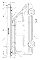
- the two carriages 7 move the movable retaining frame 3 from a resting configuration, preferably central relative to the roof T of the motor vehicle A, to an operating configuration, in which the carriages 7 reach a travel limit, positioning the movable retaining frame 3 on the lateral edge of the roof T from which the cloth of the awning system 1 must be unfolded, as illustrated in figure 5 ; conversely, when the movable retaining frame 3 goes back into the operating configuration, the two carriages 7 move the movable retaining frame 3 toward the resting configuration, illustrated in figure 1 .
- the movable retaining frame 3 when in the resting configuration, is not unremovably fixed to the longitudinal edge of the roof T of the motor vehicle A as in the prior art, but can be moved toward a more stable position and does not unbalance the motor vehicle A. Therefore, after use, during the stage of closing the system 1, the movable retaining frame 3 can be advantageously moved toward the resting configuration, in a central position that is generally suitable for better distributing the weight of the awning system 1 on the motor vehicle A.
- the movable retaining frame 3 can be positioned in such a manner as to correctly balance the weight of the awning system 1 to maintain the centre of gravity of the motor vehicle A, which bears the weight of the awning system 1, spatially in a central zone of the motor vehicle A so as not to interfere with driving or consume the tyres more on the side of the door P of the motor vehicle A.
- the tilting means 4 of the awning system 1 are suitable for tilting the movable retaining frame 3 along a tilt axis R1 parallel to the main direction of extension X of the movable retaining frame 3 itself and passing through the first hinge 6.
- the tilting means 4 are active between the base structure 2 and the movable retaining frame 3.
- the tilting means 4 comprises at least one linear electromechanical actuator, even more preferably two.
- the movable retaining frame 3 can be tilted via the tilting means 4 by at least a right angle relative to the surface of the roof T to set the movable retaining frame 3 in the correct position for the step of extending the cloth 5, which leads to the use configuration of the awning system 1.
- the awning system 1 comprises a closing element 8 for closing the movable retaining frame 3, and which is movable between a closing position in which it closes the movable retaining frame 3 and an opening position in which the cloth 5 can be unfolded from the movable retaining frame 3.
- the cloth 5 of the awning system 1 is unfoldable between a gathered position in which it is contained in the movable retaining frame 3 and a extended position in the use configuration, as illustrated in the figure 4 .
- the closing element 8 is configured to receive and accompany the cloth 5 in the movement between the opening position, illustrated in figure 7 , and the closing position, illustrated in figure 5 , during a stage of closing the awning system 1 for motor vehicles,.
- the closing element 8 performs a dual function of covering and protecting the cloth 5, as well as everything comprised in the movable retaining frame 3, and as a flaps gathering device. Therefore, unlike in the prior art, in which there are two distinct elements for covering the housing and gathering up the flaps of the cloth, with the present invention there is only one element 8 that performs both functions and at the same time considerably lightens the awning system 1 for motor vehicles.
- the awning system 1 for motor vehicles comprises opening and closing means for opening and closing the closing element 8 between the opening position and the closing position or vice versa, during the process of tilting the movable retaining frame 3.
- the means for opening and closing the closing element 8 comprises an actuating lever 9, hinged on one side to the base structure 2 and on the other side to the closing element 8, to control the opening and closing of the closing element 8 during the process of tilting the movable retaining frame 3.
- the closing element 8 is tiltable along a tilt axis R2 that passes through a second hinge 10 serving to connect the closing element 8 with the movable retaining frame 3 and is parallel to the main direction of extension X of the movable retaining frame.
- the tilt axis R2 is located on the same side as the tilt axis R1.
- the tilt axis R2 is located on the side of the movable retaining frame 3 which, in the operating configuration, is turned downward.
- the closing element 8 is preferably hinged to the movable retaining frame 3 in a manner that is diagonally opposite to the hinging of the same movable retaining frame 3 with the base structure 2, relative to the arrangement of the actuating lever 9.
- this play of levers enables simultaneous opening of the closing element 8 and of the movable retaining frame 3, avoiding the need to use hydraulic cylinders as in the prior art, thus advantageously reducing the weight of the system 1 and the associated costs of producing it.
- the closing element 8 is tilted relative to the surface of the roof T of the motor vehicle A by an angle such as to leave the area in front of the movable retaining frame 3 free of obstacles during the step of extending the cloth 5. Said angle is preferably comprised between 75° and 90°.
- the movable retaining frame 3 and/or the closing element 8 comprise trusses, made of aluminium tubing for example.
- the awning system 1 comprises at least one shaft 11 positioned transversely in the movable retaining frame 3, with which at least two rods 12 are rotatably engaged.
- the shafts 11 are configured to extend the cloth 5, which, together with the rods 12, will go to form the awning system 1 in the use configuration in which the cloth 5 is unfolded.
- the rods 12 are rotatable around an axis of rotation K of the shaft 11 perpendicular to the main direction of extension X of the movable retaining frame 3 and are configured to engage with the cloth 5.
- the shaft 11 is keyed onto a rotary electromechanical actuator 13 fastened to the movable retaining frame 3. On the side opposite the rotary electromechanical actuator 13 the shaft 11 rotates in a bushing fixed on a side opposite the one on which the rotary actuator 13 is fastened.
- a main rod 12a is fixed at the high end of the shaft 11, opposite the rotary actuator 13, and moves integrally with the rotation of the shaft 11.
- spoke-like elements 14 rotate freely on the same shaft 11; they are associated with four rod holders, preferably made of stainless steel and capable of supporting four rods 12, preferably made of aluminium tubing.
- the rods 12 are arranged in such a way as to be superimposed and not collide with those of the other shaft 11.
- the shafts 11 Upon activation with a remote control system, for example with a remote control handset, the shafts 11 start rotating one after another, staggered by a certain interval.
- the closing of the awning system 1 takes place in exactly a reverse manner compared to the opening.
- the awning system 1 of the present invention comprises a front head 15 facing the front portion of the movable retaining frame 3 and/or a rear head 16 facing the rear portion of the movable retaining frame 3.
- the front head 15 and/or rear head 16 and/or the closing element 8 are made of recycled fibreglass.
- the movable retaining frame 3, the front head 15 and the rear head 16 are aligned in the resting configuration so as to take on an aerodynamic shape.
- the awning system 1 poses less resistance to air during the travel of the motor vehicle A, thus reducing consumption and enabling more comfortable driving.
- the front head 15 comprises an opening in the front part to convey air towards a fan 17.
- the fan 17 is connected to an electrical energy accumulator.
- the air directed into the fan 17 sets the impeller of the fan 17 moving, which in turn produces electricity useful for operating the awning system 1, in particular for activating the electromechanical actuators 4,7,13.
- the awning system 1 for motor vehicles can comprise a photovoltaic panel. If the routes to be travelled by the motor vehicle A are so short as not to permit complete charging of the accumulator, the power supply of the awning system 1 can be advantageously supplemented by the photovoltaic panel.
- the awning system 1 is independent insofar as the energy aspect is concerned and is thus configured as an electrically self-powered awning system 1.
- every electromechanical actuator can be released by operating the respective key inserted in each of them so that they can be moved and manoeuvred by hand.
- the awning system 1 according to the present invention proves to be like a veritable eco-innovative solution, which, besides using recycled and recyclable materials, simplifies the structure, considerably reducing the weight of the system, and is energetically self-sufficient.
- the present invention achieves the proposed object, overcoming the aforementioned drawbacks in the prior art.
Landscapes
- Engineering & Computer Science (AREA)
- Architecture (AREA)
- Civil Engineering (AREA)
- Structural Engineering (AREA)
- Health & Medical Sciences (AREA)
- Public Health (AREA)
- Transportation (AREA)
- Mechanical Engineering (AREA)
- Building Awnings And Sunshades (AREA)
Applications Claiming Priority (1)
| Application Number | Priority Date | Filing Date | Title |
|---|---|---|---|
| ITFI20140107 | 2014-05-08 |
Publications (1)
| Publication Number | Publication Date |
|---|---|
| EP2942232A1 true EP2942232A1 (de) | 2015-11-11 |
Family
ID=51225293
Family Applications (1)
| Application Number | Title | Priority Date | Filing Date |
|---|---|---|---|
| EP14177448.9A Withdrawn EP2942232A1 (de) | 2014-05-08 | 2014-07-17 | Sonnendachsystem für ein fahrzeug |
Country Status (1)
| Country | Link |
|---|---|
| EP (1) | EP2942232A1 (de) |
Cited By (2)
| Publication number | Priority date | Publication date | Assignee | Title |
|---|---|---|---|---|
| US20190045808A1 (en) * | 2016-12-12 | 2019-02-14 | Snowie, Llc | Flavor station assembly |
| CN110453971A (zh) * | 2019-08-13 | 2019-11-15 | 北京天使印记健康管理有限公司 | 太阳能车顶帐篷 |
Citations (1)
| Publication number | Priority date | Publication date | Assignee | Title |
|---|---|---|---|---|
| EP0204670A2 (de) * | 1985-06-03 | 1986-12-10 | F.Lli Penna S.N.C. Di Penna Antonino E Giovanni | Verstellbares Planendach, insbesondere für Trödlerfahrzeuge |
-
2014
- 2014-07-17 EP EP14177448.9A patent/EP2942232A1/de not_active Withdrawn
Patent Citations (1)
| Publication number | Priority date | Publication date | Assignee | Title |
|---|---|---|---|---|
| EP0204670A2 (de) * | 1985-06-03 | 1986-12-10 | F.Lli Penna S.N.C. Di Penna Antonino E Giovanni | Verstellbares Planendach, insbesondere für Trödlerfahrzeuge |
Cited By (3)
| Publication number | Priority date | Publication date | Assignee | Title |
|---|---|---|---|---|
| US20190045808A1 (en) * | 2016-12-12 | 2019-02-14 | Snowie, Llc | Flavor station assembly |
| US10834939B2 (en) * | 2016-12-12 | 2020-11-17 | Snowie, Llc | Flavor station assembly |
| CN110453971A (zh) * | 2019-08-13 | 2019-11-15 | 北京天使印记健康管理有限公司 | 太阳能车顶帐篷 |
Similar Documents
| Publication | Publication Date | Title |
|---|---|---|
| US7740304B1 (en) | Umbrella semi-trailer drag reducer | |
| US10439549B2 (en) | Vehicle attached photovoltaic charging systems | |
| US9080374B2 (en) | Sheltering device | |
| US20110107939A1 (en) | People & cargo transit systems & vehicles | |
| KR101949166B1 (ko) | 차량용 루프탑 텐트 | |
| CN103434375B (zh) | 汽车遮阳篷 | |
| US11884144B2 (en) | Vehicle with twin canopy doors | |
| KR102101433B1 (ko) | 태양 발전이 가능한 전동카트용 접이식 캐노피 | |
| US3605941A (en) | Aerial lift with rotatable and enclosable basket | |
| CN100577459C (zh) | 全自动伸缩式汽车遮阳伞 | |
| CA2672928A1 (en) | People & cargo transit systems & vehicles | |
| US20080202708A1 (en) | Retractable door assembly for portable shelter | |
| KR20140049766A (ko) | 차량 탑재형 이동식 스윙 놀이기구 | |
| CN204940959U (zh) | 一种新型可遥控移动的伸缩式汽车库 | |
| KR101007109B1 (ko) | 개폐식 버스 승강장 | |
| CN202324732U (zh) | 汽车防护用车房 | |
| CN204124028U (zh) | 适用于带斗车型的背驮式房车结构 | |
| EP0881117A2 (de) | Temporäre Überdachung | |
| CN210027967U (zh) | 一种机场用移动式廊道 | |
| US6659530B1 (en) | Retractable cover for recreational vehicle | |
| JPH10159394A (ja) | 折り畳み式テント車庫 | |
| CN108952228A (zh) | 一种折叠式智能交通岗亭 | |
| CN104912359A (zh) | 侧立式折叠车库 | |
| CN105545035A (zh) | 转向停车位 | |
| CN110001996A (zh) | 一种机场用移动式廊道 |
Legal Events
| Date | Code | Title | Description |
|---|---|---|---|
| PUAI | Public reference made under article 153(3) epc to a published international application that has entered the european phase |
Free format text: ORIGINAL CODE: 0009012 |
|
| AK | Designated contracting states |
Kind code of ref document: A1 Designated state(s): AL AT BE BG CH CY CZ DE DK EE ES FI FR GB GR HR HU IE IS IT LI LT LU LV MC MK MT NL NO PL PT RO RS SE SI SK SM TR |
|
| AX | Request for extension of the european patent |
Extension state: BA ME |
|
| STAA | Information on the status of an ep patent application or granted ep patent |
Free format text: STATUS: THE APPLICATION IS DEEMED TO BE WITHDRAWN |
|
| 18D | Application deemed to be withdrawn |
Effective date: 20160512 |