EP2942484A1 - Traverses d'élément de lame - Google Patents
Traverses d'élément de lame Download PDFInfo
- Publication number
- EP2942484A1 EP2942484A1 EP15166907.4A EP15166907A EP2942484A1 EP 2942484 A1 EP2942484 A1 EP 2942484A1 EP 15166907 A EP15166907 A EP 15166907A EP 2942484 A1 EP2942484 A1 EP 2942484A1
- Authority
- EP
- European Patent Office
- Prior art keywords
- blade element
- blade
- cross
- tie
- ties
- Prior art date
- Legal status (The legal status is an assumption and is not a legal conclusion. Google has not performed a legal analysis and makes no representation as to the accuracy of the status listed.)
- Granted
Links
Images


Classifications
-
- F—MECHANICAL ENGINEERING; LIGHTING; HEATING; WEAPONS; BLASTING
- F01—MACHINES OR ENGINES IN GENERAL; ENGINE PLANTS IN GENERAL; STEAM ENGINES
- F01D—NON-POSITIVE DISPLACEMENT MACHINES OR ENGINES, e.g. STEAM TURBINES
- F01D5/00—Blades; Blade-carrying members; Heating, heat-insulating, cooling or antivibration means on the blades or the members
- F01D5/12—Blades
- F01D5/14—Form or construction
- F01D5/16—Form or construction for counteracting blade vibration
-
- F—MECHANICAL ENGINEERING; LIGHTING; HEATING; WEAPONS; BLASTING
- F01—MACHINES OR ENGINES IN GENERAL; ENGINE PLANTS IN GENERAL; STEAM ENGINES
- F01D—NON-POSITIVE DISPLACEMENT MACHINES OR ENGINES, e.g. STEAM TURBINES
- F01D5/00—Blades; Blade-carrying members; Heating, heat-insulating, cooling or antivibration means on the blades or the members
- F01D5/12—Blades
- F01D5/14—Form or construction
- F01D5/18—Hollow blades, i.e. blades with cooling or heating channels or cavities; Heating, heat-insulating or cooling means on blades
- F01D5/187—Convection cooling
-
- F—MECHANICAL ENGINEERING; LIGHTING; HEATING; WEAPONS; BLASTING
- F05—INDEXING SCHEMES RELATING TO ENGINES OR PUMPS IN VARIOUS SUBCLASSES OF CLASSES F01-F04
- F05D—INDEXING SCHEME FOR ASPECTS RELATING TO NON-POSITIVE-DISPLACEMENT MACHINES OR ENGINES, GAS-TURBINES OR JET-PROPULSION PLANTS
- F05D2250/00—Geometry
- F05D2250/20—Three-dimensional
- F05D2250/27—Three-dimensional hyperboloid
-
- F—MECHANICAL ENGINEERING; LIGHTING; HEATING; WEAPONS; BLASTING
- F05—INDEXING SCHEMES RELATING TO ENGINES OR PUMPS IN VARIOUS SUBCLASSES OF CLASSES F01-F04
- F05D—INDEXING SCHEME FOR ASPECTS RELATING TO NON-POSITIVE-DISPLACEMENT MACHINES OR ENGINES, GAS-TURBINES OR JET-PROPULSION PLANTS
- F05D2260/00—Function
- F05D2260/96—Preventing, counteracting or reducing vibration or noise
-
- Y—GENERAL TAGGING OF NEW TECHNOLOGICAL DEVELOPMENTS; GENERAL TAGGING OF CROSS-SECTIONAL TECHNOLOGIES SPANNING OVER SEVERAL SECTIONS OF THE IPC; TECHNICAL SUBJECTS COVERED BY FORMER USPC CROSS-REFERENCE ART COLLECTIONS [XRACs] AND DIGESTS
- Y10—TECHNICAL SUBJECTS COVERED BY FORMER USPC
- Y10T—TECHNICAL SUBJECTS COVERED BY FORMER US CLASSIFICATION
- Y10T29/00—Metal working
- Y10T29/49—Method of mechanical manufacture
- Y10T29/49316—Impeller making
- Y10T29/49336—Blade making
- Y10T29/49337—Composite blade
Definitions
- the present disclosure relates generally to components for a gas turbine engine, and more particularly to blade elements including cross-ties.
- a gas turbine engine typically includes one or more blades in each of the compressor and turbine sections of the engine. These components are exposed to high-speed air/gas flow during operation. In addition, gas turbine engine components are exposed to high temperatures. As such, airfoils are typically provided with cooling channels. Airfoil structures experience high levels of stress during operation which may limit component operation life. There exists a desire to extend the operational life of components.
- Manufacturing of airfoil components can include using ceramic cores to form passages in airfoils.
- Conventional methods include the use of stiffening rods to supporting cast elements. These rods are removed with cast elements during manufacture of the component. Accordingly, there rods do not provide structural support during operation.
- a blade element for a gas turbine engine includes a first inner surface of the blade element, wherein the first inner surface is associated with a first outer blade surface of the blade element, and a second inner surface of the blade element, wherein the second inner surface is associated with a second outer blade surface of the blade element and wherein the second inner surface is opposite from the first inner surface.
- the blade element also includes a cross-tie configured to connect the first inner surface to the second inner surface, wherein the cross-tie is positioned along a trailing edge of the blade element and the cross-tie is configured to reduce vibration mode effects of the blade element.
- a method for manufacturing a blade element of a gas turbine engine includes forming a first blade surface of the blade element, wherein the first blade surface includes a first inner surface, and forming a second blade surface of the blade element, wherein the second blade surface includes a second inner surface and wherein the second inner surface is opposite from the first inner surface.
- the method also includes forming a cross-tie configured to connect the first inner surface to the second inner surface along a trailing edge of the blade element, wherein the cross-tie is positioned and configured to reduce vibration mode effects of the blade element.
- a blade element such as fan blades, turbine blades and vanes
- a cross-tie is a structural element configured to provide rigidity to an interior passage or hollow section of a blade element.
- each cross-tie may have a curved profile with surface blended to inner walls of a blade element.
- cross-ties may include a non-circular cross section.
- Cross-ties may be placed and configured to provide support and rigidity to unsupported areas of a blade element. Cross-ties may additionally allow for internal connections within a blade element without restricting airflow or changing heat transfer of the blade element.
- Another aspect of the disclosure is directed to manufacturing blade elements to include one or more cross-ties.
- a cast having positives and negatives may be formed for manufacturing a blade element having one or more cross-ties.
- the terms “a” or “an” shall mean one or more than one.
- the term “plurality” shall mean two or more than two.
- the term “another” is defined as a second or more.
- the terms “including” and/or “having” are open ended (e.g., comprising).
- the term “or” as used herein is to be interpreted as inclusive or meaning any one or any combination. Therefore, “A, B or C” means “any of the following: A; B; C; A and B; A and C; B and C; A, B and C". An exception to this definition will occur only when a combination of elements, functions, steps or acts are in some way inherently mutually exclusive.
- FIGS. 1A-1C depict graphical representations of a blade element according to one or more embodiments.
- blade element 100 is shown including leading edge 105, blade surface 106 (e.g., a first blade surface) and trailing edge 110.
- Blade element 100 may be one of a turbine blade, fan blade, vane, and gas turbine engine component.
- FIG. 1A depicts blade element 100 including base structure 120.
- blade element 100 may include one or more cross-ties configured to connect a first blade surface, such as an inner surface of blade surface 106, to a second inner blade surface.
- cross-ties may connect inner surfaces of the blade element.
- Cross-ties may be positioned near and/or along trailing edge 110 of blade element 100, wherein the cross-tie is positioned and configured to reduce vibration mode effects of the blade element 100.
- vibration mode effects can relate to one or more of blade surface stress, blade surface strain, vibratory stress, vibratory strain, and blade deformation.
- Cross-ties may be configured to provide stiffening to reduce one or more of the vibratory effects. It should be appreciated that the frequency of vibratory stress may be driven up or down. While stress should be generally reduced everywhere in blade element 100, there are situations where the vibratory frequency needs to be driven upward.
- cross-ties as discussed herein may be configured to stress and/or strain associated with the vibratory mode of a blade element.
- cross-ties of blade element 100 are positioned between 20-90% of a span length, shown generally as area 115 in FIG. 1A , of blade element 100.
- the trailing edge portion of the blade may relate to portions of the blade element 100 near trailing edge 110.
- Blade element 100 may include a plurality of cross-ties along the trailing edge 110 in area 115. Each cross-tie may be formed integrally with an inner surface of blade element 100 within a particular area shown as section 116. Section or area 116 is shown in more detail with respect to FIGS. 2A-2B .
- cross-ties may be positioned in other portions of blade element 100.
- FIG. 1B depicts a top down representation of blade element 100.
- blade element 100 includes a first blade surface of the blade element, blade surface 106 with corresponding first inner surface 108, and a second blade surface, blade surface 107 with corresponding second inner surface 109.
- Blade surface 108 is opposite from blade surface 109, wherein the blade surfaces are between leading edge 105 and trailing edge 110.
- blade surface 108 is opposite from blade surface 109 meaning the surfaces are on opposing ends of an interior portion. It can be appreciated that surfaces 108 and 109 may be parallel, substantially parallel, or not parallel. It can also be appreciated that surfaces 108 and 109 may not correspond to the surface shape characteristics of surfaces 106 and 107.
- blade element 100 includes a representation of cross-tie 130 1 .
- Cross-tie 130 1 is configured to connect blade surface 106 to blade surface 107.
- Cross-tie 130 1 is positioned near trailing edge 110 of blade element 100.
- Cross-tie 130 1 may be configured to reduce vibration mode of blade element 100 by providing increased stiffness for walls of the blade element.
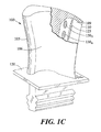
- FIG. 1C depicts a cut-away representation of blade element 100.
- blade element 100 may include cooling area 125 to provide cooling air/air flow for cooling blade element 100.
- Cooling area 125 may be one or more hollow sections of blade element 100.
- Cross-ties 130 1-n are shown relative to inner surface 109 and near trailing edge 110. In certain embodiments, cross-ties 130 1-n may be positioned to provide structural integrity without restricting airflow.
- FIG. 2A depicts a graphical representation of a blade element cross-tie according to one or more embodiments.
- section 200 of a blade element e.g., blade element 100
- cross-tie 205 includes a first portion blended to an inner wall of blade surface 206, a second portion blended to an inner wall of blade surface 207, and a non-circular cross-section 210 between the first and second portions.
- non-circular cross-section 210 is reduced in size relative to the first and second portions of the cross-tie blended to blade surfaces.
- Cross-tie 205 may be configured to provide a connection between surfaces 206 and 207 and provide both in-plane (shear) and out-of-plane (compressive/tensile) support. By providing stiffening, cross-tie 205 can reduce the extent to which surfaces 206 and 207 participate in the vibration mode of the blade element.
- FIG. 2B depicts a cross-sectional view of the cross-tie of FIG. 2A according to one or more embodiments.
- Blade element section 250 is a cross sectional view along reference line A-A of FIG. 2A , which is associated with the central axis of the cross-tie 205.
- cross-tie 205 is formed to include a non-circular blend between first and second portions of the cross-tie blended to blade surfaces. Non-circular curved/bending is shown by arcs 255, 260, 265 and 270.
- Cross-tie 205 includes a long axis oriented with the direction of centrifugal pull of a blade element (e.g., blade element 105).
- cross-tie 205 increases stability of the blade element by supporting the first and second blade element surfaces in a hollow section of the blade element.
- Cross-tie 205 may be configured to provide in-plane and out-of-plane support for the blade element.
- In-plane support provided by the blade element may relate support along an axis of cross-tie 205, while out-of-plane support may relate to support for vibratory and steady state stress of the blade element in general.
- FIG. 3 depicts a graphical representation of a blade element cast according to one or more embodiments.
- blade elements e.g., blade element 100
- Cast 300 is a simplified representation of a cast element including negatives and positives that may be employed to fabricate a blade element as described herein. As shown in FIG. 3 , cast 300 includes a plurality of negatives, shown as 305 1-n , to allow for cross-ties to be formed. Cast 300 also includes a plurality of positives, shown as 310 1-n , to allow for cooling passages to be formed.
- FIG. 4 depicts a process for manufacturing a blade element (e.g., blade element 100) according to one or more embodiments.
- Process 400 may be initiated at block 405 with determining one or more cross-tie locations for a blade element.
- modelling of a blade element may indicate one or more locations where additional stiffness or an internal connection is required.
- determining one or more cross-tie locations for the blade element includes modelling a blade element for one or more of vibratory frequency, vibratory mode shape and vibratory stress.
- a cast for the blade element may be generated.
- a cast may be formed at block 410 to include one or more negatives and positives, to form cross-ties and cooling paths.
- Process 400 may continue to block 415 to fabricate a blade element based on the cast generated at block 410 to include one or more cross-ties.
- fabricating a blade element of a gas turbine engine at block 415 includes forming a first blade surface of the blade element, and forming a second blade surface of the blade element, wherein the second blade surface is opposite from the first blade surface.
- Fabricating a blade element of a gas turbine engine at block 415 may also include forming one or more cross-ties configured to connect the inner surface of a first blade surface to the inner surface of a second blade surface on a trailing edge of the blade element.
- Forming cross-ties at block 415 can include forming a plurality of cross-ties along the trailing edge of the blade element.
Landscapes
- Engineering & Computer Science (AREA)
- Mechanical Engineering (AREA)
- General Engineering & Computer Science (AREA)
- Turbine Rotor Nozzle Sealing (AREA)
Applications Claiming Priority (1)
| Application Number | Priority Date | Filing Date | Title |
|---|---|---|---|
| US201461991328P | 2014-05-09 | 2014-05-09 |
Publications (3)
| Publication Number | Publication Date |
|---|---|
| EP2942484A1 true EP2942484A1 (fr) | 2015-11-11 |
| EP2942484B1 EP2942484B1 (fr) | 2020-04-22 |
| EP2942484B2 EP2942484B2 (fr) | 2023-05-03 |
Family
ID=53051744
Family Applications (1)
| Application Number | Title | Priority Date | Filing Date |
|---|---|---|---|
| EP15166907.4A Active EP2942484B2 (fr) | 2014-05-09 | 2015-05-08 | Traverses d'élément de pale |
Country Status (2)
| Country | Link |
|---|---|
| US (1) | US20150322797A1 (fr) |
| EP (1) | EP2942484B2 (fr) |
Families Citing this family (3)
| Publication number | Priority date | Publication date | Assignee | Title |
|---|---|---|---|---|
| US11168566B2 (en) * | 2016-12-05 | 2021-11-09 | MTU Aero Engines AG | Turbine blade comprising a cavity with wall surface discontinuities and process for the production thereof |
| US11220913B2 (en) * | 2019-10-23 | 2022-01-11 | Rolls-Royce Corporation | Gas turbine engine blades with airfoil plugs for selected tuning |
| GB202216739D0 (en) * | 2022-11-10 | 2022-12-28 | Rolls Royce Plc | Tie for a component |
Citations (4)
| Publication number | Priority date | Publication date | Assignee | Title |
|---|---|---|---|---|
| US4278400A (en) * | 1978-09-05 | 1981-07-14 | United Technologies Corporation | Coolable rotor blade |
| EP1431514A2 (fr) * | 2002-12-17 | 2004-06-23 | General Electric Company | Aube de turbine avec une sortie à la Venturi |
| US20050084380A1 (en) * | 2003-10-16 | 2005-04-21 | Pratt & Whitney Canada Corp. | Hollow turbine blade stiffening |
| US7780414B1 (en) * | 2007-01-17 | 2010-08-24 | Florida Turbine Technologies, Inc. | Turbine blade with multiple metering trailing edge cooling holes |
Family Cites Families (16)
| Publication number | Priority date | Publication date | Assignee | Title |
|---|---|---|---|---|
| US4180373A (en) * | 1977-12-28 | 1979-12-25 | United Technologies Corporation | Turbine blade |
| US4297077A (en) | 1979-07-09 | 1981-10-27 | Westinghouse Electric Corp. | Cooled turbine vane |
| US6602047B1 (en) * | 2002-02-28 | 2003-08-05 | General Electric Company | Methods and apparatus for cooling gas turbine nozzles |
| US6890154B2 (en) * | 2003-08-08 | 2005-05-10 | United Technologies Corporation | Microcircuit cooling for a turbine blade |
| US7575414B2 (en) * | 2005-04-01 | 2009-08-18 | General Electric Company | Turbine nozzle with trailing edge convection and film cooling |
| US7438527B2 (en) * | 2005-04-22 | 2008-10-21 | United Technologies Corporation | Airfoil trailing edge cooling |
| US8210814B2 (en) * | 2008-06-18 | 2012-07-03 | General Electric Company | Crossflow turbine airfoil |
| US20100022678A1 (en) | 2008-07-24 | 2010-01-28 | Zimmer, Inc. | Reduction of free radicals in crosslinked polyethylene by infrared heating |
| US8109726B2 (en) | 2009-01-19 | 2012-02-07 | Siemens Energy, Inc. | Turbine blade with micro channel cooling system |
| US8764394B2 (en) * | 2011-01-06 | 2014-07-01 | Siemens Energy, Inc. | Component cooling channel |
| US9017027B2 (en) * | 2011-01-06 | 2015-04-28 | Siemens Energy, Inc. | Component having cooling channel with hourglass cross section |
| GB201102719D0 (en) * | 2011-02-17 | 2011-03-30 | Rolls Royce Plc | Cooled component for the turbine of a gas turbine engine |
| FR2978210B1 (fr) * | 2011-07-21 | 2018-02-16 | Safran Aircraft Engines | Procede d'alimentation d'un film fluide d'amortissement d'un palier de guidage d'un arbre de turbomachine |
| US9297261B2 (en) † | 2012-03-07 | 2016-03-29 | United Technologies Corporation | Airfoil with improved internal cooling channel pedestals |
| US9249668B2 (en) * | 2012-04-24 | 2016-02-02 | United Technologies Corporation | Airfoil with break-way, free-floating damper member |
| WO2014186109A1 (fr) † | 2013-05-15 | 2014-11-20 | United Technologies Corporation | Socle de turbulateur à passage de refroidissement de profil aérodynamique de moteur à turbine à gaz |
-
2015
- 2015-04-23 US US14/694,435 patent/US20150322797A1/en not_active Abandoned
- 2015-05-08 EP EP15166907.4A patent/EP2942484B2/fr active Active
Patent Citations (4)
| Publication number | Priority date | Publication date | Assignee | Title |
|---|---|---|---|---|
| US4278400A (en) * | 1978-09-05 | 1981-07-14 | United Technologies Corporation | Coolable rotor blade |
| EP1431514A2 (fr) * | 2002-12-17 | 2004-06-23 | General Electric Company | Aube de turbine avec une sortie à la Venturi |
| US20050084380A1 (en) * | 2003-10-16 | 2005-04-21 | Pratt & Whitney Canada Corp. | Hollow turbine blade stiffening |
| US7780414B1 (en) * | 2007-01-17 | 2010-08-24 | Florida Turbine Technologies, Inc. | Turbine blade with multiple metering trailing edge cooling holes |
Also Published As
| Publication number | Publication date |
|---|---|
| EP2942484B1 (fr) | 2020-04-22 |
| US20150322797A1 (en) | 2015-11-12 |
| EP2942484B2 (fr) | 2023-05-03 |
Similar Documents
| Publication | Publication Date | Title |
|---|---|---|
| US9017038B2 (en) | Variable performance vaneaxial fan with high efficiency | |
| US8668453B2 (en) | Cooling system having reduced mass pin fins for components in a gas turbine engine | |
| US5295789A (en) | Turbomachine flow-straightener blade | |
| CN106150560B (zh) | 具有带槽道的销的涡轮叶片阻尼系统 | |
| CN106133277B (zh) | 可变导向叶片延伸的可变筋条 | |
| RU2541078C2 (ru) | Турбинная лопатка и способ ее изготовления | |
| US7186082B2 (en) | Cooled rotor blade and method for cooling a rotor blade | |
| JP5612136B2 (ja) | 複数の直線により形状が定義されるインペラの形成方法およびインペラ | |
| EP2441964B1 (fr) | Conception de profil aérodynamique pour un compresseur axial et compresseur axial | |
| JP2003314201A (ja) | ターボ機械に用いられる動翼 | |
| CN105829653A (zh) | 涡轮机组件或组件集以及相关的涡轮机 | |
| JP7104379B2 (ja) | 軸流型のファン、圧縮機及びタービンの翼の設計方法、並びに、当該設計により得られる翼 | |
| EP3034804A1 (fr) | Entretoise de pré-diffuseur pour moteur de turbine à gaz | |
| EP2434096A2 (fr) | Aube de turbine à gaz comprenant un socle de conduction | |
| US8303252B2 (en) | Airfoil with cooling passage providing variable heat transfer rate | |
| EP2942484B1 (fr) | Traverses d'élément de pale | |
| CN105008668A (zh) | 具有扭曲的肋的扭曲的燃气涡轮发动机翼面 | |
| US20160201469A1 (en) | Mateface surfaces having a geometry on turbomachinery hardware | |
| DE602005007275D1 (de) | Hälfte einer hohlen Gebläseschaufel, hohle Gebläseschaufel für Gasturbinentriebwerk, sowie entsprechendes Herstellungsverfahren | |
| ITFI20130261A1 (it) | "centrifugal compressor impeller with blades having an s-shaped trailing edge" | |
| CN106050321A (zh) | 冷却翼型件、导向静叶及用于制造其的方法 | |
| CN104234754B (zh) | 用于燃气涡轮的翼型件、叶片和导叶 | |
| JP6469897B2 (ja) | タービンブレード | |
| US10544687B2 (en) | Shrouded blade of a gas turbine engine | |
| WO2017146724A1 (fr) | Amortissemment pour pales de turbine creuses façonnées |
Legal Events
| Date | Code | Title | Description |
|---|---|---|---|
| PUAI | Public reference made under article 153(3) epc to a published international application that has entered the european phase |
Free format text: ORIGINAL CODE: 0009012 |
|
| AK | Designated contracting states |
Kind code of ref document: A1 Designated state(s): AL AT BE BG CH CY CZ DE DK EE ES FI FR GB GR HR HU IE IS IT LI LT LU LV MC MK MT NL NO PL PT RO RS SE SI SK SM TR |
|
| AX | Request for extension of the european patent |
Extension state: BA ME |
|
| 17P | Request for examination filed |
Effective date: 20160509 |
|
| RBV | Designated contracting states (corrected) |
Designated state(s): AL AT BE BG CH CY CZ DE DK EE ES FI FR GB GR HR HU IE IS IT LI LT LU LV MC MK MT NL NO PL PT RO RS SE SI SK SM TR |
|
| RAP1 | Party data changed (applicant data changed or rights of an application transferred) |
Owner name: UNITED TECHNOLOGIES CORPORATION |
|
| STAA | Information on the status of an ep patent application or granted ep patent |
Free format text: STATUS: EXAMINATION IS IN PROGRESS |
|
| 17Q | First examination report despatched |
Effective date: 20170822 |
|
| GRAP | Despatch of communication of intention to grant a patent |
Free format text: ORIGINAL CODE: EPIDOSNIGR1 |
|
| STAA | Information on the status of an ep patent application or granted ep patent |
Free format text: STATUS: GRANT OF PATENT IS INTENDED |
|
| INTG | Intention to grant announced |
Effective date: 20190529 |
|
| RIN1 | Information on inventor provided before grant (corrected) |
Inventor name: THORNTON, LANE Inventor name: SNYDER, DANIEL A. Inventor name: SIMPSON, ALEX J. |
|
| GRAJ | Information related to disapproval of communication of intention to grant by the applicant or resumption of examination proceedings by the epo deleted |
Free format text: ORIGINAL CODE: EPIDOSDIGR1 |
|
| STAA | Information on the status of an ep patent application or granted ep patent |
Free format text: STATUS: EXAMINATION IS IN PROGRESS |
|
| GRAP | Despatch of communication of intention to grant a patent |
Free format text: ORIGINAL CODE: EPIDOSNIGR1 |
|
| STAA | Information on the status of an ep patent application or granted ep patent |
Free format text: STATUS: GRANT OF PATENT IS INTENDED |
|
| INTC | Intention to grant announced (deleted) | ||
| INTG | Intention to grant announced |
Effective date: 20191105 |
|
| GRAS | Grant fee paid |
Free format text: ORIGINAL CODE: EPIDOSNIGR3 |
|
| GRAA | (expected) grant |
Free format text: ORIGINAL CODE: 0009210 |
|
| STAA | Information on the status of an ep patent application or granted ep patent |
Free format text: STATUS: THE PATENT HAS BEEN GRANTED |
|
| AK | Designated contracting states |
Kind code of ref document: B1 Designated state(s): AL AT BE BG CH CY CZ DE DK EE ES FI FR GB GR HR HU IE IS IT LI LT LU LV MC MK MT NL NO PL PT RO RS SE SI SK SM TR |
|
| REG | Reference to a national code |
Ref country code: CH Ref legal event code: EP |
|
| REG | Reference to a national code |
Ref country code: IE Ref legal event code: FG4D |
|
| REG | Reference to a national code |
Ref country code: DE Ref legal event code: R096 Ref document number: 602015050994 Country of ref document: DE |
|
| REG | Reference to a national code |
Ref country code: AT Ref legal event code: REF Ref document number: 1260321 Country of ref document: AT Kind code of ref document: T Effective date: 20200515 |
|
| REG | Reference to a national code |
Ref country code: LT Ref legal event code: MG4D |
|
| REG | Reference to a national code |
Ref country code: NL Ref legal event code: MP Effective date: 20200422 |
|
| PG25 | Lapsed in a contracting state [announced via postgrant information from national office to epo] |
Ref country code: IS Free format text: LAPSE BECAUSE OF FAILURE TO SUBMIT A TRANSLATION OF THE DESCRIPTION OR TO PAY THE FEE WITHIN THE PRESCRIBED TIME-LIMIT Effective date: 20200822 Ref country code: LT Free format text: LAPSE BECAUSE OF FAILURE TO SUBMIT A TRANSLATION OF THE DESCRIPTION OR TO PAY THE FEE WITHIN THE PRESCRIBED TIME-LIMIT Effective date: 20200422 Ref country code: PT Free format text: LAPSE BECAUSE OF FAILURE TO SUBMIT A TRANSLATION OF THE DESCRIPTION OR TO PAY THE FEE WITHIN THE PRESCRIBED TIME-LIMIT Effective date: 20200824 Ref country code: NL Free format text: LAPSE BECAUSE OF FAILURE TO SUBMIT A TRANSLATION OF THE DESCRIPTION OR TO PAY THE FEE WITHIN THE PRESCRIBED TIME-LIMIT Effective date: 20200422 Ref country code: SE Free format text: LAPSE BECAUSE OF FAILURE TO SUBMIT A TRANSLATION OF THE DESCRIPTION OR TO PAY THE FEE WITHIN THE PRESCRIBED TIME-LIMIT Effective date: 20200422 Ref country code: NO Free format text: LAPSE BECAUSE OF FAILURE TO SUBMIT A TRANSLATION OF THE DESCRIPTION OR TO PAY THE FEE WITHIN THE PRESCRIBED TIME-LIMIT Effective date: 20200722 Ref country code: GR Free format text: LAPSE BECAUSE OF FAILURE TO SUBMIT A TRANSLATION OF THE DESCRIPTION OR TO PAY THE FEE WITHIN THE PRESCRIBED TIME-LIMIT Effective date: 20200723 Ref country code: FI Free format text: LAPSE BECAUSE OF FAILURE TO SUBMIT A TRANSLATION OF THE DESCRIPTION OR TO PAY THE FEE WITHIN THE PRESCRIBED TIME-LIMIT Effective date: 20200422 |
|
| REG | Reference to a national code |
Ref country code: AT Ref legal event code: MK05 Ref document number: 1260321 Country of ref document: AT Kind code of ref document: T Effective date: 20200422 |
|
| PG25 | Lapsed in a contracting state [announced via postgrant information from national office to epo] |
Ref country code: HR Free format text: LAPSE BECAUSE OF FAILURE TO SUBMIT A TRANSLATION OF THE DESCRIPTION OR TO PAY THE FEE WITHIN THE PRESCRIBED TIME-LIMIT Effective date: 20200422 Ref country code: LV Free format text: LAPSE BECAUSE OF FAILURE TO SUBMIT A TRANSLATION OF THE DESCRIPTION OR TO PAY THE FEE WITHIN THE PRESCRIBED TIME-LIMIT Effective date: 20200422 Ref country code: BG Free format text: LAPSE BECAUSE OF FAILURE TO SUBMIT A TRANSLATION OF THE DESCRIPTION OR TO PAY THE FEE WITHIN THE PRESCRIBED TIME-LIMIT Effective date: 20200722 Ref country code: RS Free format text: LAPSE BECAUSE OF FAILURE TO SUBMIT A TRANSLATION OF THE DESCRIPTION OR TO PAY THE FEE WITHIN THE PRESCRIBED TIME-LIMIT Effective date: 20200422 |
|
| PG25 | Lapsed in a contracting state [announced via postgrant information from national office to epo] |
Ref country code: AL Free format text: LAPSE BECAUSE OF FAILURE TO SUBMIT A TRANSLATION OF THE DESCRIPTION OR TO PAY THE FEE WITHIN THE PRESCRIBED TIME-LIMIT Effective date: 20200422 |
|
| REG | Reference to a national code |
Ref country code: DE Ref legal event code: R026 Ref document number: 602015050994 Country of ref document: DE |
|
| PG25 | Lapsed in a contracting state [announced via postgrant information from national office to epo] |
Ref country code: EE Free format text: LAPSE BECAUSE OF FAILURE TO SUBMIT A TRANSLATION OF THE DESCRIPTION OR TO PAY THE FEE WITHIN THE PRESCRIBED TIME-LIMIT Effective date: 20200422 Ref country code: ES Free format text: LAPSE BECAUSE OF FAILURE TO SUBMIT A TRANSLATION OF THE DESCRIPTION OR TO PAY THE FEE WITHIN THE PRESCRIBED TIME-LIMIT Effective date: 20200422 Ref country code: CZ Free format text: LAPSE BECAUSE OF FAILURE TO SUBMIT A TRANSLATION OF THE DESCRIPTION OR TO PAY THE FEE WITHIN THE PRESCRIBED TIME-LIMIT Effective date: 20200422 Ref country code: MC Free format text: LAPSE BECAUSE OF FAILURE TO SUBMIT A TRANSLATION OF THE DESCRIPTION OR TO PAY THE FEE WITHIN THE PRESCRIBED TIME-LIMIT Effective date: 20200422 Ref country code: RO Free format text: LAPSE BECAUSE OF FAILURE TO SUBMIT A TRANSLATION OF THE DESCRIPTION OR TO PAY THE FEE WITHIN THE PRESCRIBED TIME-LIMIT Effective date: 20200422 Ref country code: AT Free format text: LAPSE BECAUSE OF FAILURE TO SUBMIT A TRANSLATION OF THE DESCRIPTION OR TO PAY THE FEE WITHIN THE PRESCRIBED TIME-LIMIT Effective date: 20200422 Ref country code: LI Free format text: LAPSE BECAUSE OF NON-PAYMENT OF DUE FEES Effective date: 20200531 Ref country code: CH Free format text: LAPSE BECAUSE OF NON-PAYMENT OF DUE FEES Effective date: 20200531 Ref country code: DK Free format text: LAPSE BECAUSE OF FAILURE TO SUBMIT A TRANSLATION OF THE DESCRIPTION OR TO PAY THE FEE WITHIN THE PRESCRIBED TIME-LIMIT Effective date: 20200422 Ref country code: SM Free format text: LAPSE BECAUSE OF FAILURE TO SUBMIT A TRANSLATION OF THE DESCRIPTION OR TO PAY THE FEE WITHIN THE PRESCRIBED TIME-LIMIT Effective date: 20200422 Ref country code: IT Free format text: LAPSE BECAUSE OF FAILURE TO SUBMIT A TRANSLATION OF THE DESCRIPTION OR TO PAY THE FEE WITHIN THE PRESCRIBED TIME-LIMIT Effective date: 20200422 |
|
| PLBI | Opposition filed |
Free format text: ORIGINAL CODE: 0009260 |
|
| PLAX | Notice of opposition and request to file observation + time limit sent |
Free format text: ORIGINAL CODE: EPIDOSNOBS2 |
|
| PG25 | Lapsed in a contracting state [announced via postgrant information from national office to epo] |
Ref country code: SK Free format text: LAPSE BECAUSE OF FAILURE TO SUBMIT A TRANSLATION OF THE DESCRIPTION OR TO PAY THE FEE WITHIN THE PRESCRIBED TIME-LIMIT Effective date: 20200422 Ref country code: PL Free format text: LAPSE BECAUSE OF FAILURE TO SUBMIT A TRANSLATION OF THE DESCRIPTION OR TO PAY THE FEE WITHIN THE PRESCRIBED TIME-LIMIT Effective date: 20200422 |
|
| 26 | Opposition filed |
Opponent name: SAFRAN AIRCRAFT ENGINES Effective date: 20210121 |
|
| REG | Reference to a national code |
Ref country code: BE Ref legal event code: MM Effective date: 20200531 |
|
| RAP2 | Party data changed (patent owner data changed or rights of a patent transferred) |
Owner name: RAYTHEON TECHNOLOGIES CORPORATION |
|
| PG25 | Lapsed in a contracting state [announced via postgrant information from national office to epo] |
Ref country code: LU Free format text: LAPSE BECAUSE OF NON-PAYMENT OF DUE FEES Effective date: 20200508 |
|
| PG25 | Lapsed in a contracting state [announced via postgrant information from national office to epo] |
Ref country code: IE Free format text: LAPSE BECAUSE OF NON-PAYMENT OF DUE FEES Effective date: 20200508 |
|
| PG25 | Lapsed in a contracting state [announced via postgrant information from national office to epo] |
Ref country code: SI Free format text: LAPSE BECAUSE OF FAILURE TO SUBMIT A TRANSLATION OF THE DESCRIPTION OR TO PAY THE FEE WITHIN THE PRESCRIBED TIME-LIMIT Effective date: 20200422 Ref country code: BE Free format text: LAPSE BECAUSE OF NON-PAYMENT OF DUE FEES Effective date: 20200531 |
|
| PLBB | Reply of patent proprietor to notice(s) of opposition received |
Free format text: ORIGINAL CODE: EPIDOSNOBS3 |
|
| PG25 | Lapsed in a contracting state [announced via postgrant information from national office to epo] |
Ref country code: TR Free format text: LAPSE BECAUSE OF FAILURE TO SUBMIT A TRANSLATION OF THE DESCRIPTION OR TO PAY THE FEE WITHIN THE PRESCRIBED TIME-LIMIT Effective date: 20200422 Ref country code: MT Free format text: LAPSE BECAUSE OF FAILURE TO SUBMIT A TRANSLATION OF THE DESCRIPTION OR TO PAY THE FEE WITHIN THE PRESCRIBED TIME-LIMIT Effective date: 20200422 Ref country code: CY Free format text: LAPSE BECAUSE OF FAILURE TO SUBMIT A TRANSLATION OF THE DESCRIPTION OR TO PAY THE FEE WITHIN THE PRESCRIBED TIME-LIMIT Effective date: 20200422 |
|
| PG25 | Lapsed in a contracting state [announced via postgrant information from national office to epo] |
Ref country code: MK Free format text: LAPSE BECAUSE OF FAILURE TO SUBMIT A TRANSLATION OF THE DESCRIPTION OR TO PAY THE FEE WITHIN THE PRESCRIBED TIME-LIMIT Effective date: 20200422 |
|
| REG | Reference to a national code |
Ref country code: DE Ref legal event code: R081 Ref document number: 602015050994 Country of ref document: DE Owner name: RAYTHEON TECHNOLOGIES CORPORATION (N.D.GES.D.S, US Free format text: FORMER OWNER: UNITED TECHNOLOGIES CORPORATION, FARMINGTON, CONN., US Ref country code: DE Ref legal event code: R081 Ref document number: 602015050994 Country of ref document: DE Owner name: RTX CORPORATION (N.D.GES.D. STAATES DELAWARE),, US Free format text: FORMER OWNER: UNITED TECHNOLOGIES CORPORATION, FARMINGTON, CONN., US |
|
| PUAH | Patent maintained in amended form |
Free format text: ORIGINAL CODE: 0009272 |
|
| STAA | Information on the status of an ep patent application or granted ep patent |
Free format text: STATUS: PATENT MAINTAINED AS AMENDED |
|
| 27A | Patent maintained in amended form |
Effective date: 20230503 |
|
| AK | Designated contracting states |
Kind code of ref document: B2 Designated state(s): AL AT BE BG CH CY CZ DE DK EE ES FI FR GB GR HR HU IE IS IT LI LT LU LV MC MK MT NL NO PL PT RO RS SE SI SK SM TR |
|
| REG | Reference to a national code |
Ref country code: DE Ref legal event code: R102 Ref document number: 602015050994 Country of ref document: DE |
|
| P01 | Opt-out of the competence of the unified patent court (upc) registered |
Effective date: 20230520 |
|
| PGFP | Annual fee paid to national office [announced via postgrant information from national office to epo] |
Ref country code: DE Payment date: 20250423 Year of fee payment: 11 |
|
| PGFP | Annual fee paid to national office [announced via postgrant information from national office to epo] |
Ref country code: GB Payment date: 20250423 Year of fee payment: 11 |
|
| PGFP | Annual fee paid to national office [announced via postgrant information from national office to epo] |
Ref country code: FR Payment date: 20250423 Year of fee payment: 11 |
|
| REG | Reference to a national code |
Ref country code: DE Ref legal event code: R081 Ref document number: 602015050994 Country of ref document: DE Owner name: RTX CORPORATION (N.D.GES.D. STAATES DELAWARE),, US Free format text: FORMER OWNER: RAYTHEON TECHNOLOGIES CORPORATION (N.D.GES.D.STAATES DELAWARE), ARLINGTON, VA, US |