EP2942585A1 - Kältekreislaufvorrichtung - Google Patents
Kältekreislaufvorrichtung Download PDFInfo
- Publication number
- EP2942585A1 EP2942585A1 EP13868444.4A EP13868444A EP2942585A1 EP 2942585 A1 EP2942585 A1 EP 2942585A1 EP 13868444 A EP13868444 A EP 13868444A EP 2942585 A1 EP2942585 A1 EP 2942585A1
- Authority
- EP
- European Patent Office
- Prior art keywords
- refrigerant
- evaporator
- ejector
- heat exchanger
- refrigeration cycle
- Prior art date
- Legal status (The legal status is an assumption and is not a legal conclusion. Google has not performed a legal analysis and makes no representation as to the accuracy of the status listed.)
- Granted
Links
Images


Classifications
-
- F—MECHANICAL ENGINEERING; LIGHTING; HEATING; WEAPONS; BLASTING
- F25—REFRIGERATION OR COOLING; COMBINED HEATING AND REFRIGERATION SYSTEMS; HEAT PUMP SYSTEMS; MANUFACTURE OR STORAGE OF ICE; LIQUEFACTION SOLIDIFICATION OF GASES
- F25B—REFRIGERATION MACHINES, PLANTS OR SYSTEMS; COMBINED HEATING AND REFRIGERATION SYSTEMS; HEAT PUMP SYSTEMS
- F25B41/00—Fluid-circulation arrangements
-
- F—MECHANICAL ENGINEERING; LIGHTING; HEATING; WEAPONS; BLASTING
- F25—REFRIGERATION OR COOLING; COMBINED HEATING AND REFRIGERATION SYSTEMS; HEAT PUMP SYSTEMS; MANUFACTURE OR STORAGE OF ICE; LIQUEFACTION SOLIDIFICATION OF GASES
- F25B—REFRIGERATION MACHINES, PLANTS OR SYSTEMS; COMBINED HEATING AND REFRIGERATION SYSTEMS; HEAT PUMP SYSTEMS
- F25B2341/00—Details of ejectors not being used as compression device; Details of flow restrictors or expansion valves
- F25B2341/001—Ejectors not being used as compression device
- F25B2341/0012—Ejectors with the cooled primary flow at high pressure
-
- F—MECHANICAL ENGINEERING; LIGHTING; HEATING; WEAPONS; BLASTING
- F25—REFRIGERATION OR COOLING; COMBINED HEATING AND REFRIGERATION SYSTEMS; HEAT PUMP SYSTEMS; MANUFACTURE OR STORAGE OF ICE; LIQUEFACTION SOLIDIFICATION OF GASES
- F25B—REFRIGERATION MACHINES, PLANTS OR SYSTEMS; COMBINED HEATING AND REFRIGERATION SYSTEMS; HEAT PUMP SYSTEMS
- F25B25/00—Machines, plants or systems, using a combination of modes of operation covered by two or more of the groups F25B1/00 - F25B23/00
- F25B25/005—Machines, plants or systems, using a combination of modes of operation covered by two or more of the groups F25B1/00 - F25B23/00 using primary and secondary systems
Definitions
- the present invention relates to a refrigeration cycle apparatus including a refrigerant circuit.
- a conventional chilling unit is known that is composed of a plurality of compressors that are connected in parallel and a plurality of evaporators of a water heat exchanger type.
- the evaporators are connected in series with each other via water pipes. Coolant water is gradually cooled through heat exchange with refrigerant in the evaporators, and thus, the evaporating temperature of the refrigerant gradually decreases from the inlet side. Consequently, an average evaporating temperature is higher than that in the case of cooling with a refrigerating machine composed of one compressor.
- This configuration contributes to improving the COP of a refrigeration cycle and efficient operation of the refrigeration cycle (see, for example, Patent Literature 1).
- Patent Literature 1 Japanese Unexamined Patent Application Publication No. 2006-329601
- the conventional chilling unit described above requires a plurality of compressors, and thus increased cost is required.
- a plurality of control boards need to be mounted in accordance with the number of the compressors, resulting in an increase in size and cost of the unit.
- a refrigeration cycle apparatus includes: a first refrigerant circuit connected to a refrigerant discharging part of a compressor, a condenser, a first expansion valve, a first evaporator, and a refrigerant suction portion of an ejector; a second refrigerant circuit branching off from connection piping between an outlet side of the condenser and the first expansion valve and connected to a refrigerant inflow portion of the ejector; and a third refrigerant circuit connected to a refrigerant outflow portion of the ejector, a second evaporator, and a refrigerant suction portion of the compressor, wherein the first evaporator is a water heat exchanger that exchanges heat between refrigerant flowing in a refrigerant circuit including the first evaporator and a liquid heat medium different from the refrigerant, the second evaporator is a water heat exchanger that exchanges heat between refrigerant flowing in a refrigerant
- the evaporating temperature of the second evaporator can be higher than the evaporating temperature of the first evaporator by utilizing a pressure rise effect of the ejector.
- the temperature of the liquid heat medium can be gradually reduced. In this manner, refrigerant at an evaporating temperature higher than that of refrigerant in the first evaporator is sucked into the compressor, and thus, the COP of the refrigeration cycle increases, resulting in enhancement of the operation efficiency.
- the resulting refrigerant circuit is more economic than a conventional system using two compressors.
- FIG. 1 A refrigeration cycle apparatus according to Embodiment 1 of the present invention is described with reference to Fig. 1 .
- the refrigeration cycle apparatus illustrated in Fig. 1 is configured as an outdoor unit 100 including a compressor 101, a condenser 102, a first expansion valve 103, first and second evaporators 104 and 106 that perform heat exchange between refrigerant and a liquid heat medium different from the refrigerant, and an ejector 105.
- the condenser 102 is an air heat exchanger that exchanges heat between refrigerant and air.
- the first evaporator 104 and the second evaporator 106 exchange heat between refrigerant and a liquid heat medium (liquid such as water or brine) and will be hereinafter also referred to as water heat exchangers.
- a liquid heat medium liquid such as water or brine
- the compressor 101, the condenser 102, the first expansion valve 103, the first evaporator 104, and a refrigerant suction portion 205 of the ejector 105 are connected together by refrigerant pipes and form a first refrigerant circuit.
- a pipe branching off from the refrigerant pipe between the condenser 102 and the first expansion valve 103 is connected to a refrigerant inflow portion 204 of the ejector 105 and constitutes a second refrigerant circuit.
- a refrigerant outflow portion 203 of the ejector 105, the second evaporator 106, and a refrigerant suction portion of the compressor 101 are connected together by refrigerant pipes and form a third refrigerant circuit.
- the first evaporator 104 and the second evaporator 106 are configured such that refrigerant and the liquid heat medium flow in opposite directions so as to exchange heat.
- Inlet/outlet parts of the first evaporator 104 and the second evaporator 106 for the liquid heat medium project from the casing in order to establish connection to the outside (e.g., an indoor unit 108).
- the first evaporator 104 and the second evaporator 106 are connected to an indoor heat exchanger 109 of the indoor unit 108 on a heat load side, and form a liquid heat medium circulation circuit together with a water supply 107 for transferring the liquid heat medium.
- the water supply 107 is disposed such that the liquid heat medium flows from the second evaporator 106 to the first evaporator 104.
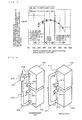
- Fig. 2 illustrates an example of the ejector 105.
- Fig. 2 also shows an internal pressure distribution corresponding to the configuration of the ejector 105.
- the ejector 105 includes a nozzle 201, a mixer 202, a diffuser (a refrigerant outflow portion) 203, a refrigerant inflow portion 204, and a refrigerant suction portion 205.
- the nozzle 201 includes a pressure reducing portion 201 a, a nozzle throat 201 b, and a flared portion 201 c.
- "e" and "f” denote points in a mollier chart that will be described later.
- the ejector 105 illustrated in Fig. 2 operates in the following manner. Refrigerant that has flowed from the refrigerant inflow portion 204 expands in the pressure reducing portion 201 a under reduced pressure as the channel area decreases. Thereafter, the speed of the refrigerant increases under reduced pressure and reaches an acoustic speed in the nozzle throat 201 b. The pressure of the refrigerant at the acoustic speed decreases with a further increase in the speed in the flared portion 201 c. In this manner, ultrafast two-phase gas-liquid refrigerant flows out of the nozzle 201.
- refrigerant sucked from the refrigerant suction portion 205 of the ejector 105 is drawn into the ultrafast refrigerant (suction refrigerant) due to the pressure difference between the refrigerant suction portion 205 and the outlet of the nozzle 201.
- the ultrafast refrigerant and the low-speed suction refrigerant start being mixed (a refrigerant mixture).
- the pressure of the refrigerant mixture restores (increases) through exchange of momenta between the ultrafast refrigerant and the suction refrigerant.
- the speed reduction due to the channel enlargement causes a dynamic pressure to be converted into a static pressure and the pressure increases. Consequently, the refrigerant mixture flows out of the diffuser (the refrigerant outflow portion) 203.
- the first evaporator 104 and the second evaporator 106 may be plate heat exchangers as disclosed in, for example, Japanese Unexamined Patent Application Publication No. 2012-2425 .
- heat transmission plates 1042 and heat transmission plates 1043 are alternately stacked.
- a reinforcing side plate 1041 is disposed as the frontmost plate, and a reinforcing side plate 1044 is disposed as the rearmost plate.
- the reinforcing side plate 1041 is a substantially rectangular plate and includes a first inlet pipe 1045, a first outlet pipe 1046, a second outlet pipe 1047, and a second inlet pipe 1048 at the four corners, respectively.
- each of the heat transmission plates 1042 and 1043 is also a substantially rectangular plate and includes a first inlet, a first outlet, a second inlet, and a second outlet at the four corners, respectively.
- the heat transmission plates 1042 and 1043 have wave shapes that are substantially V shaped when viewed from the direction in which the heat transmission plates 1042 and 1043 are stacked, and the heat transmission plates 1042 and 1043 are so stacked that the wave shapes of one of the heat transmission heat transmission plates 1042 and 1043 are displaced from those of the other one.
- the substantially V shaped form of the wave shapes of the heat transmission plates 1042 are inverted from those of the wave shapes of the heat transmission plates 1043.
- the rearmost reinforcing side plate 1044 is a substantially rectangular plate.
- the rearmost reinforcing side plate 1044 includes none of a first inlet pipe, a first outlet pipe, a second inlet pipe, and a second outlet pipe.
- the inversely oriented V-shaped wave shapes are overlaid on each other, so that channels where a complicated flow occurs are formed between the heat transmission plates 1042 and the heat transmission plates 1043.
- a first channel through which first fluid (e.g., water) that has flowed from the first inlet pipe 1045 flows out of the first outlet pipe 1046 is formed between the rear surface of the heat transmission plates 1043 and the front surface of the heat transmission plates 1042.
- second fluid e.g., refrigerant
- the first fluid that has flowed from the outside into the first inlet pipe 1045 flows through passages formed by overlaying the first inlets of the heat transmission plates 1042 and 1043 on each other, and flows into the first channels.
- the first fluid that has flowed into the first channels gradually expands along the shorter axis flows along the longer axis, and flows out of the first outlets.
- the first fluid that has flowed out from the first outlets flows in passages formed by overlaying the first outlets on each other, and flows out through the first outlet pipe 1046.
- the second fluid that has flowed from the outside into the second inlet pipe 1048 flows through passages formed by overlaying the second inlets of the heat transmission plates 1042 and 1043 on each other, and flows into the second channels.
- the second fluid that has flowed into the second channels gradually expands along the shorter axis flows along the longer axis, and flows out of the second outlets.
- the second fluid that has flowed out from the second outlets flows in passages formed by overlaying the second outlets on each other, and flows out through the second outlet pipe 1047.
- the first fluid flowing in the first channels and the second fluid flowing in the second channels exchange heat through the heat transmission plates 1042 and 1043 when passing through the portions of wave shapes.
- the portions of wave shapes will be referred to as heat exchange channels.
- the condenser 102 includes a fan 1026 and an air heat exchanger 1027.
- the fan 1026 is a combination of a wing type propeller and a motor that drives and rotates the propeller.
- the motor and the propeller rotate at predetermined numbers of revolution with electric power supplied from the outside.
- the air heat exchanger 1027 is made of a long refrigerant pipe which is bent into the shape of an L-shaped flat plate and with which a large number of fins made of aluminum thin plates are in close contact. Refrigerant in the refrigerant pipe and air around the fins exchange heat.
- the airflow rate of air passing between the fins is increased and adjusted by the fan 1026, and the amount of heat exchange is increased and adjusted.
- Fig. 5 is a mollier chart showing an operating state of a refrigeration cycle apparatus of Embodiment 1.
- Alphabets with black circles in Fig. 5 refer to the locations of the black circles in Fig. 1 .
- High-temperature high-pressure gas refrigerant in a state that has been delivered by the compressor 101 is condensed through heat exchange with outdoor air in the condenser 102 and becomes high-temperature high-pressure liquid refrigerant (in a state b).
- the refrigerant in the state b is divided into a portion flowing toward the first expansion valve 103 and a portion flowing toward the ejector 105.
- the refrigerant flowing toward the first expansion valve 103 is subjected to pressure reduction in the first expansion valve 103 and becomes a state c, then heated and vaporized by a liquid heat medium at a relatively low temperature cooled by the second evaporator 106 and becomes a state d in the first evaporator 104, and then is sucked into the refrigerant suction portion 205 of the ejector 105.
- the refrigerant flowing from the condenser 102 into the refrigerant inflow portion 204 of the ejector 105 is subjected to pressure reduction (state e) in the nozzle 201 of the ejector 105, and merges with refrigerant vaporized in the first evaporator 104 to be in a state f.
- the refrigerant is then subjected to a pressure rise in the mixer 202 of the ejector 105 and the diffuser (the refrigerant outflow portion) 203 to be in a state g, and flows into the second evaporator 106.
- the refrigerant is vaporized through heat exchange with a liquid heat medium at a relatively high temperature heated by the indoor heat exchanger 109 to be in a state h, and is sucked into the compressor 101.
- the foregoing states are repeated, thereby forming a refrigeration cycle.
- Fig. 6 shows temperature distribution in the flow directions of refrigerant and a liquid heat medium in the first evaporator 104 and the second evaporator 106 illustrated in Fig. 1 .
- reference numeral 601 denotes the temperature of a liquid heat medium
- reference numeral 602 denotes the refrigerant temperature of the first evaporator 104
- reference numeral 603 denotes a refrigerant temperature of the second evaporator 106.
- the liquid heat medium that has reached a high temperature in the indoor heat exchanger 109 and has returned to the outdoor unit 100 is cooled and has its temperature reduced while passing through the first evaporator 104 and the second evaporator 106.
- the evaporating temperature in the first evaporator 104 is relatively lower than the evaporating temperature in the second evaporator 106.
- the evaporating temperature can be increased by ⁇ Teje. Then, the refrigerant that has flowed from the second evaporator 106 is caused to return to a suction side of the compressor 101.
- the pressure rise effect in the ejector 105 can cause the evaporating temperature in the second evaporator 106 to be higher than the evaporating temperature in the first evaporator 104.
- the heated liquid heat medium flows in the order from the second evaporator 106 to the first evaporator 104 so that the liquid heat medium can be gradually cooled. In this manner, the refrigerant whose evaporating temperature is higher than that in the first evaporator 104 can be sucked into the compressor 101.
- the COP of the refrigeration cycle is enhanced, and the operation efficiency can be increased.
- Embodiment 1 is advantageous in that a refrigerant circuit including one compressor can constitute an economically efficient refrigeration cycle.
- a refrigeration cycle apparatus is different from that of Embodiment 1 in that a first evaporator 104 and a second evaporator 106 have different capacities. Specifically, as illustrated in Fig. 22 , the capacity of the second evaporator 106 is larger than that of the first evaporator 104.
- the capacity difference between the first evaporator 104 and the second evaporator 106 enhances the COP of the refrigeration cycle.
- the principle thereof is as follows.
- High-temperature high-pressure refrigerant that has flowed from a condenser 102 is divided into a portion flowing toward a first expansion valve 103 and a portion flowing toward an ejector 105.
- the performance of the first evaporator 104 degrades by a degree corresponding to a decrease in the capacity of the first evaporator 104, and thus, the amount of refrigerant flowing toward the first expansion valve 103 decreases.
- the performance of the second evaporator 106 increases by a degree corresponding to an increase in the capacity of the second evaporator 106, and thus, the amount of refrigerant flowing toward the ejector 105 increases.
- the degree of pressure rise obtained by power recovery in the ejector 105 is defined by the following equation, and the degree of the pressure rise increases as the amount of refrigerant flowing into the ejector 105 increases.
- Gn is the flow rate of refrigerant flowing into the ejector 105
- hg is an enthalpy of the refrigerant inflow portion 204 of the ejector 105
- he is an enthalpy obtained when the cross section expands from the inlet to the outlet of the nozzle 201 illustrated in Fig. 2
- Ge is the flow rate of refrigerant sucked by the ejector 105
- pe is the density of the refrigerant suction portion 205 of the ejector 105.
- the increase in the capacity of the second evaporator 106 increases the driven flow of the ejector 105, and the amount of collected power in the ejector 105 increases. Accordingly, the evaporating temperature of the second evaporator 106 increases, and the suction temperature of the compressor 101 increases. Consequently, the COP of the refrigeration cycle increases, thereby enhancing the operation efficiency.
- Fig. 7 shows COP characteristics of a refrigeration cycle in a case where the sum of the capacity of the first evaporator 104 and the capacity of the second evaporator 106 is fixed and the proportion of the first evaporator 104 is varied. With the COP at 50% on the abscissa, the capacity of the first evaporator 104 is equal to that of the second evaporator 106. As shown in Fig. 7 , the COP is increased by reducing the capacity of the first evaporator 104 and increasing the capacity of the second evaporator 106, independently of the ejector efficiency. Specifically, the COP is effectively increased when the capacity of the first evaporator 104 is in the range from 30% to 50%, especially when the first evaporator 104 is around 40% of the entire capacity.
- the first evaporator 104 and the second evaporator 106 of Embodiment 1 or 2 are vertically stacked.
- Fig. 8 illustrates an example of installation of the first evaporator 104, the second evaporator 106, and the ejector 105 in the first example.
- the first evaporator 104 is positioned higher than the second evaporator 106.
- the ejector 105 is disposed such that a refrigerant inflow portion 204 is positioned higher 104 and 106 than a diffuser (a refrigerant outflow portion) 203.
- a refrigerant outlet 802 of the first evaporator 104 is connected to a refrigerant suction portion 205 of the ejector 105 by a pipe 805.
- a diffuser (a refrigerant outflow portion) 203 of the ejector 105 is connected to the second evaporator 106 by a pipe 806.
- a liquid heat medium inlet 811 of the first evaporator 104 is connected to a liquid heat medium outlet 814 of the second evaporator 106 by a pipe 815.
- Single-phase liquid or two-phase gas-liquid refrigerant that has flowed into the first evaporator 104 flows from a lower portion to an upper portion of the first evaporator 104 while being heated and vaporized with a liquid heat medium flowing in a liquid heat medium circulation circuit.
- the refrigerant that has flowed from the refrigerant outlet 802 of the first evaporator 104 is sucked into the refrigerant suction portion 205 of the ejector 105 through the pipe 805.
- the refrigerant that has flowed from the refrigerant inflow portion 204 and refrigerant sucked from the first evaporator 104 into the refrigerant suction portion 205 sequentially flow in a mixer 202 of the ejector 105, the diffuser (the refrigerant outflow portion) 203, and the pipe 806 in this order, and then flows into the refrigerant inlet 803 of the second evaporator 106.
- the two-phase gas-liquid refrigerant that has flowed into the second evaporator 106 flows toward an upper portion of the second evaporator 106 while being heated and vaporized with the liquid heat medium flowing in the liquid heat medium circulation circuit, and then flows out from the refrigerant outlet 804.
- the liquid heat medium of the liquid heat medium circulation circuit flows from the liquid heat medium inlet 813 into the second evaporator 106. Then, the liquid heat medium is cooled with relatively high-temperature refrigerant whose pressure has been increased in the ejector 105, and flows out from the liquid heat medium outlet 814. Then, the liquid heat medium flows from the liquid heat medium inlet 811 of the first evaporator 104 into the first evaporator 104 through the pipe 815. Thereafter, the liquid heat medium is cooled with relatively low-temperature refrigerant immediately before the pressure rise in the ejector 105, and flows out from the liquid heat medium outlet 812.
- the refrigerant and the liquid heat medium flow in opposite directions, that is, a counterflow is formed.
- the second evaporator 106 is disposed at a lower level, and the diffuser (the refrigerant outflow portion) 203 of the ejector 105 is disposed below the refrigerant inflow portion 204 and the refrigerant suction portion 205 of the ejector 105, the pipe 805 and the pipe 806 are shortened.
- a pressure loss in connection piping is reduced so that the efficiency of the refrigeration cycle can be increased.
- the ejector 105, the first evaporator 104, and the second evaporator 106 can be made compact, thereby reducing the space and cost.
- the first evaporator 104 and the second evaporator 106 are disposed in a horizontal line, that is, arranged side by side, and the refrigerant inflow portion 204 of the ejector 105 is positioned higher than the diffuser (the refrigerant outflow portion) 203 of the ejector 105.
- the other parts of the configuration and operation are the same as those in Embodiment 1 and the first example of Embodiment 3.
- Fig. 11 illustrates an example of installation of the first evaporator 104, the second evaporator 106, and the ejector 105 in the second example.
- the first evaporator 104 and the second evaporator 106 are arranged side by side.
- the ejector 105 is disposed such that the refrigerant inflow portion 204 is positioned higher than the diffuser (the refrigerant outflow portion) 203.
- the refrigerant outlet 802 of the first evaporator 104 is connected to the refrigerant suction portion 205 of the ejector 105 by the pipe 805.
- the diffuser (the refrigerant outflow portion) 203 of the ejector 105 is connected to the second evaporator 106 by the pipe 806.
- the liquid heat medium outlet 812 of the first evaporator 104 is connected to the liquid heat medium inlet 813 of the second evaporator 106 by the pipe 815.
- the first evaporator 104 and the second evaporator 106 are arranged side by side, and the diffuser (the refrigerant outflow portion) 203 of the ejector 105 is located below the refrigerant inflow portion 204 and the refrigerant suction portion 205 of the ejector 105.
- the pipe 805 and the pipe 806 are shortened.
- the connection method is effective when the configuration is restricted by the height of installation. In a manner similar to those illustrated in Figs. 8 through 10 , a pressure loss in connection piping is reduced, and the efficiency of the refrigeration cycle is enhanced.
- Fig. 12 illustrates a configuration of a refrigeration cycle apparatus according to Embodiment 4 of the present invention.
- the refrigeration cycle apparatus illustrated in Fig. 12 is configured as an outdoor unit 100 including a first high and low pressure heat exchanger 1101 and a second high and low pressure heat exchanger 1102 that exchange heat between refrigerants in addition to a compressor 101, a condenser 102, a first expansion valve 103, a first evaporator 104, an ejector 105, and a second evaporator 106.
- the compressor 101, the condenser 102, a high-pressure side of the first high and low pressure heat exchanger 1101, a high-pressure side of the second high and low pressure heat exchanger 1102, the first expansion valve 103, the first evaporator 104, a low-pressure side of the second high and low pressure heat exchanger 1102, and a refrigerant suction portion 205 of the ejector 105 are connected in series to each other, thereby forming a first refrigerant circuit.
- the first refrigerant circuit of Embodiment 4 is obtained by adding a high-pressure side channel of the first high and low pressure heat exchanger 1101 and a high-pressure side channel of the second high and low pressure heat exchanger 1102 between the condenser 102 and the first expansion valve 103 of the first refrigerant circuit of one of Embodiments 1 to 3 and adding a low-pressure side channel of the second high and low pressure heat exchanger 1102 between the first evaporator 104 and the refrigerant suction portion 205 of the ejector 105.
- a pipe branching off from a refrigerant pipe between the condenser 102 and the first high and low pressure heat exchanger 1101 is connected to a refrigerant inflow portion 204 of the ejector 105 and forms a second refrigerant circuit.
- a diffuser (a refrigerant outflow portion) 203 of the ejector 105, the second evaporator 106, a low-pressure side of the first high and low pressure heat exchanger 1101, and a refrigerant suction portion of the compressor 101 are connected to each other by refrigerant pipes, thereby forming a third refrigerant circuit.
- the third refrigerant circuit of Embodiment 4 is obtained by adding a low-pressure side channel of the first high and low pressure heat exchanger 1101 between the second evaporator 106 and the compressor 101 of the third refrigerant circuit of one of Embodiments 1 to 3.
- Fig. 13 illustrates an example of the high and low pressure heat exchanger used in Embodiment 4.
- the high and low pressure heat exchangers 1101 and 1102 are composed of double pipes, low-pressure low-temperature refrigerant flows in an inner space 1201 of the inner pipe, and high-temperature high-pressure refrigerant flows in a ring space 1202 of an outer pipe located on an outer side of the inner pipe such that these refrigerants exchange heat.
- the high and low pressure heat exchanger illustrated in Fig. 13(b) is composed of double pipes of the outer pipe 2101 and the inner pipe 2102.
- the inner pipe 2102 is provided with a plurality of fins 2102a that are arranged around the axis such that heat exchange performance between the refrigerant flowing in the inner space 2104 of the inner pipe 2102 and the refrigerant flowing in the ring space 2103 of the outer pipe 2101 is enhanced.
- the inner pipe may be provided with a plurality of spiral pipes.
- Fig. 14 is a mollier chart showing an operating state of the refrigeration cycle apparatus illustrated in Fig. 12 .
- the state of refrigerant at the outlet of the condenser 102 is the same as that in Embodiment 1.
- Refrigerant that has flowed from the condenser 102 toward the first expansion valve 103 is cooled to be in a state b' through heat exchange with low-temperature low-pressure refrigerant that has flowed from the second evaporator 106 in the first high and low pressure heat exchanger 1101.
- this refrigerant becomes a state b" through heat exchange with low-temperature low-pressure refrigerant that has flowed from the first evaporator 104 in the second high and low pressure heat exchanger 1102, and flows into the first expansion valve 103.
- the refrigerant subjected to pressure reduction in the first expansion valve 103 becomes a state c, and passes through the first evaporator 104 to be in a state d'.
- This refrigerant is heated with high-temperature high-pressure refrigerant in the second high and low pressure heat exchanger 1102 to be in a state d and is sucked into the ejector 105.
- the refrigerant passes through the ejector 105 and the second evaporator 106 to be in a state h, and then is heated by the first high and low pressure heat exchanger 1101 to be in a state h' and is sucked into the compressor 101.
- the refrigeration cycle apparatus of Embodiment 4 uses the high and low pressure heat exchangers 1101 and 1102 in order to change refrigerant that flows out of the first and second evaporators 104 and 106 into two-phase refrigerant.
- a configuration (b) including high and low pressure heat exchangers enables the refrigerant flowing out from the outlets of the first and second evaporators 104 and 106 to be in the two-phase state so that the refrigerant is in a superheat state in the high and low pressure heat exchangers.
- the heat transfer coefficient of the first and second evaporators 104 and 106 can be increased, resulting in increases in the pressure of the refrigerant suction portion 205 of the ejector 105 and the suction pressure of the compressor 101.
- the temperature of refrigerant sucked into the compressor 101 increases, thereby enhancing the efficiency of the refrigeration cycle.
- the COP ratio gradually increases to a certain length, and thus, an appropriate length is preferably selected.
- Fig. 17 illustrates a configuration of a refrigeration cycle apparatus according to Embodiment 5 of the present invention.
- the refrigeration cycle apparatus illustrated in Fig. 17 is configured as an outdoor unit 100 including a gas-liquid separator 1701 in addition to a compressor 101, a condenser 102, a first expansion valve 103, a first evaporator 104, an ejector 105, and a second evaporator 106.
- the compressor 101, the condenser 102, the first expansion valve 103, the first evaporator 104, and the ejector 105 are connected to each other by refrigerant pipes, thereby forming a first refrigerant circuit.
- the refrigeration cycle apparatus also includes a second refrigerant circuit that branches off from a refrigerant pipe between the condenser 102 and the first expansion valve 103 and is connected to the refrigerant inflow portion 204 of the ejector 105.
- a refrigerant outflow portion 203 of the ejector 105, a gas-liquid separator 1701, the second evaporator 106, a refrigerant suction portion of the compressor 101 are connected to each other by refrigerant pipes, thereby forming a third refrigerant circuit.
- the third refrigerant circuit of Embodiment 5 is obtained by inserting the gas-liquid separator 1701 between the ejector 105 of the third refrigerant circuit and the second evaporator 106 of one of Embodiments 1 to 3.
- the refrigeration cycle apparatus also includes a bypass circuit 1702 that connects a gas refrigerant outlet of the gas-liquid separator 1701 and an outlet of the second evaporator 106 through first flow control means 1703.
- the bypass circuit 1702 may be a capillary tube.
- the gas-liquid separator 1701 is composed of a refrigerant inlet, an outlet of gas refrigerant, and an outlet of liquid refrigerant.
- Fig. 18 illustrates an example of the gas-liquid separator 1701.
- the gas-liquid separator 1701 includes a container 301 having a cylindrical side wall 301 a, a top wall 301 b, and a bottom wall 301 c, an inlet pipe 302 penetrating through the top wall 301 b, an upper outlet pipe 303 arranged on the side of the inlet pipe 302 and attached to the top wall 301 b, and a lower outlet pipe 304 attached to the bottom wall 301 c of the container 301.
- the refrigerant liquid 307b is separated from refrigerant steam 308 and is dropped by gravity along the side wall 301 a, and accumulates as refrigerant liquid 307e on the bottom of the container 301.
- the refrigerant steam 308 flows out of the container 301 through the upper outlet pipe 303.
- the refrigerant liquid 307a that is not blown from the lateral hole in the inlet pipe 302 and flows to a lower portion accumulates on the bottom surface of the inlet pipe 302, and flows out downward as refrigerant liquid 307c through the lower hole. Then, the refrigerant liquid 307c merges with the refrigerant liquid 307e that has accumulated on the bottom of the container 301 together with the refrigerant liquid 307b, and flows out of the container 301 through the lower outlet pipe 304.
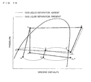
- Fig. 19 is a mollier chart showing an operating state of the refrigeration cycle apparatus illustrated in Fig. 17 .
- Refrigerant in the state g that has flowed out of the ejector 105 is separated into liquid refrigerant (state g') and gas refrigerant (state g") in the gas-liquid separator 1701.
- the liquid refrigerant is heated by liquid heat medium in the second evaporator 106.
- the gas refrigerant is subjected to flow control in the first flow control means 1703, and then merges with refrigerant that has flowed out of the second evaporator 106 to be in a state h, and is sucked into the compressor 101.
- liquid refrigerant separated in the gas-liquid separator 1701 is caused to flow into the second evaporator 106 so that the refrigerant speed in the second evaporator 106 decreases and a pressure loss in the second evaporator 106 decreases.
- the decrease in pressure loss in the second evaporator 106 increases the evaporating temperature of the second evaporator 106 so that the suction pressure of the compressor 101 increases, thereby obtaining efficient operation of the refrigeration cycle.
- Fig. 20 illustrates a configuration of a refrigeration cycle apparatus according to Embodiment 6 of the present invention.
- the refrigeration cycle apparatus of Embodiment 6 is configured as an outdoor unit 100 including an internal heat exchanger 2001 and second flow control means 2002 in addition to a compressor 101, a condenser 102, a first expansion valve 103, a first evaporator 104, an ejector 105, and a second evaporator 106.
- the compressor 101, the condenser 102, a high-pressure side of the internal heat exchanger 2001, the first expansion valve 103, the first evaporator 104, and a refrigerant suction portion 205 of the ejector 105 are sequentially connected to each other, thereby forming a first refrigerant circuit (obtained by adding a high-pressure side channel of the internal heat exchanger 2001 between the condenser 102 and the first expansion valve 103 of the first refrigerant circuit of Embodiments 1 to 3).
- a pipe branching off from a refrigerant pipe between the condenser 102 and the internal heat exchanger 2001 is connected to the refrigerant inflow portion 204 of the ejector 105, thereby forming a second refrigerant circuit.
- a diffuser (a refrigerant outflow portion) 203 of the ejector 105, the second evaporator 106, a refrigerant suction portion of the compressor 101 are connected to each other by refrigerant pipes, thereby forming a third refrigerant circuit.
- the refrigeration cycle apparatus further includes an injection circuit 2003 branching off from between an outlet side of the condenser 102 and an inlet side of the internal heat exchanger 2001 and is connected to an intermediate pressure port of the compressor 101 through the second flow control means 2002 and the low-pressure side channel of the internal heat exchanger 2001.
- the internal heat exchanger 2001 may have the same configuration as that of the high and low pressure heat exchanger described above, and/or may use the water heat exchanger described above as an internal heat exchanger.
- Fig. 21 is a mollier chart showing an operating state of the refrigeration cycle apparatus illustrated in Fig. 20 .
- the refrigerant in the high-temperature high-pressure state b that has flowed out from the condenser 102 is divided into refrigerant flowing toward the internal heat exchanger 2001 and refrigerant flowing toward the ejector 105.
- the refrigerant flowing toward the internal heat exchanger 2001 is then divided into refrigerant flowing toward the internal heat exchanger 2001 and refrigerant flowing toward the second flow control means 2002.
- the refrigerant in the state i subjected to flow control and pressure reduction in the second flow control means 2002 is heated through heat exchange with the high-temperature high-pressure refrigerant in the internal heat exchanger 2001 to be in a state j, and flows into portions around an intermediate pressure of the compressor 101.
- the refrigerant that has flowed into an intermediate pressure of the compressor 101 is mixed with refrigerant that has flowed from a suction portion of the compressor 101 and is compressed to be in a state k, and then is compressed again.
- refrigerant in the state b that has flowed into a high-pressure side of the internal heat exchanger 2001 is cooled through heat exchange with low-temperature refrigerant flowing in the low-pressure side of the internal heat exchanger 2001 to be in a state c', and flows into the first expansion valve 103. Subsequent operation is the same as that in Fig. 5 , and description thereof will not be repeated.
- Refrigerant that branches from the refrigerant pipe between the outlet side of the condenser 102 and the inlet side of the internal heat exchanger 2001 and has become a low temperature in the second flow control means 2002 exchanges heat with high-temperature refrigerant in the internal heat exchanger 2001.
- the refrigerant subjected to the heat exchange is caused to flow (injected) into the intermediate pressure port of the compressor 101, thereby temporarily cooling refrigerant compressed in the compressor 101 and compressing the refrigerant again.
- the discharge temperature of the compressor 101 is lower than that in the case of using no injection, and superheat of the motor of the compressor 101 can be reduced, thereby increasing the reliability.
- advantageously, low-temperature water that cannot be operated in order to protect the motor against superheat can be produced.
- 100 outdoor unit 101 compressor, 102 condenser, 103 first expansion valve, 104 first evaporator, 105 ejector, 106 second evaporator, 107 water supply, 108 indoor unit, 109 indoor heat exchanger, 201 nozzle of ejector, 202, mixer of ejector, 203 diffuser (refrigerant outflow portion) of ejector, 204 refrigerant inlet of ejector, 205 refrigerant suction portion of ejector, 1101 first high and low pressure heat exchanger, 1102 second high and low pressure heat exchanger, 1701 gas-liquid separator, 1702 bypass circuit, 1703 first flow control means, 2001 internal heat exchanger, 2002 second flow control means, 2003 injection circuit.
Landscapes
- Engineering & Computer Science (AREA)
- Physics & Mathematics (AREA)
- Mechanical Engineering (AREA)
- Thermal Sciences (AREA)
- General Engineering & Computer Science (AREA)
- Other Air-Conditioning Systems (AREA)
- Heat-Exchange Devices With Radiators And Conduit Assemblies (AREA)
Applications Claiming Priority (2)
| Application Number | Priority Date | Filing Date | Title |
|---|---|---|---|
| JP2012285786 | 2012-12-27 | ||
| PCT/JP2013/074012 WO2014103436A1 (ja) | 2012-12-27 | 2013-09-06 | 冷凍サイクル装置 |
Publications (3)
| Publication Number | Publication Date |
|---|---|
| EP2942585A1 true EP2942585A1 (de) | 2015-11-11 |
| EP2942585A4 EP2942585A4 (de) | 2016-11-30 |
| EP2942585B1 EP2942585B1 (de) | 2021-03-17 |
Family
ID=51020540
Family Applications (1)
| Application Number | Title | Priority Date | Filing Date |
|---|---|---|---|
| EP13868444.4A Not-in-force EP2942585B1 (de) | 2012-12-27 | 2013-09-06 | Kältekreislaufvorrichtung |
Country Status (4)
| Country | Link |
|---|---|
| EP (1) | EP2942585B1 (de) |
| JP (1) | JPWO2014103436A1 (de) |
| CN (1) | CN203704419U (de) |
| WO (1) | WO2014103436A1 (de) |
Cited By (1)
| Publication number | Priority date | Publication date | Assignee | Title |
|---|---|---|---|---|
| DE102015009255A1 (de) * | 2015-07-16 | 2017-01-19 | Linde Aktiengesellschaft | Verfahren zum Abkühlen eines Prozessstromes |
Families Citing this family (9)
| Publication number | Priority date | Publication date | Assignee | Title |
|---|---|---|---|---|
| CN106016613B (zh) * | 2016-05-31 | 2020-04-21 | 广东美的制冷设备有限公司 | 节能空调系统 |
| JP6547781B2 (ja) * | 2016-06-16 | 2019-07-24 | 株式会社デンソー | 冷凍サイクル装置 |
| JP2019138577A (ja) * | 2018-02-13 | 2019-08-22 | 株式会社デンソー | 冷凍サイクル装置 |
| JP7135450B2 (ja) * | 2018-05-31 | 2022-09-13 | 株式会社デンソー | 冷凍サイクル装置 |
| CN112815561B (zh) * | 2019-10-31 | 2022-03-25 | 广东美的白色家电技术创新中心有限公司 | 制冷设备 |
| CN115698607A (zh) * | 2020-06-15 | 2023-02-03 | 三菱电机株式会社 | 制冷循环装置 |
| CN114484946A (zh) * | 2020-10-28 | 2022-05-13 | 江森自控科技公司 | 具有串流蒸发器的冷却器系统 |
| CN112594950B (zh) * | 2020-12-29 | 2024-02-09 | 深圳市海吉源科技有限公司 | 一种低温冷水制冷机组及控制方法 |
| KR20230095493A (ko) | 2021-12-22 | 2023-06-29 | 현대자동차주식회사 | 이젝터가 포함된 차량용 열관리 시스템 |
Family Cites Families (13)
| Publication number | Priority date | Publication date | Assignee | Title |
|---|---|---|---|---|
| JP2009133624A (ja) * | 2005-03-14 | 2009-06-18 | Mitsubishi Electric Corp | 冷凍空調装置 |
| US7779647B2 (en) * | 2005-05-24 | 2010-08-24 | Denso Corporation | Ejector and ejector cycle device |
| JP4885481B2 (ja) | 2005-05-30 | 2012-02-29 | 株式会社前川製作所 | 冷却装置の運転方法 |
| JP2007051833A (ja) * | 2005-08-18 | 2007-03-01 | Denso Corp | エジェクタ式冷凍サイクル |
| JP2007057177A (ja) * | 2005-08-25 | 2007-03-08 | Denso Corp | 蒸気圧縮式冷凍サイクル装置 |
| JP2007147198A (ja) * | 2005-11-29 | 2007-06-14 | Denso Corp | エジェクタを用いた蒸気圧縮式冷凍サイクルおよびその低圧系部品 |
| JP4737001B2 (ja) * | 2006-01-13 | 2011-07-27 | 株式会社デンソー | エジェクタ式冷凍サイクル |
| JP4651627B2 (ja) | 2007-01-19 | 2011-03-16 | 三菱電機株式会社 | 冷凍空調装置 |
| JP5004645B2 (ja) * | 2007-04-23 | 2012-08-22 | 三菱電機株式会社 | 冷凍空調装置 |
| JP2009138952A (ja) * | 2007-12-03 | 2009-06-25 | Denso Corp | ブライン式冷却装置 |
| JP5526494B2 (ja) * | 2008-05-14 | 2014-06-18 | ダイキン工業株式会社 | 冷凍装置 |
| JP5430667B2 (ja) * | 2009-10-20 | 2014-03-05 | 三菱電機株式会社 | ヒートポンプ装置 |
| JP5819592B2 (ja) | 2010-06-16 | 2015-11-24 | 三菱電機株式会社 | プレート式熱交換器及びヒートポンプ装置 |
-
2013
- 2013-09-06 EP EP13868444.4A patent/EP2942585B1/de not_active Not-in-force
- 2013-09-06 WO PCT/JP2013/074012 patent/WO2014103436A1/ja not_active Ceased
- 2013-09-06 JP JP2014554186A patent/JPWO2014103436A1/ja active Pending
- 2013-12-27 CN CN201320897498.7U patent/CN203704419U/zh not_active Expired - Lifetime
Cited By (1)
| Publication number | Priority date | Publication date | Assignee | Title |
|---|---|---|---|---|
| DE102015009255A1 (de) * | 2015-07-16 | 2017-01-19 | Linde Aktiengesellschaft | Verfahren zum Abkühlen eines Prozessstromes |
Also Published As
| Publication number | Publication date |
|---|---|
| WO2014103436A1 (ja) | 2014-07-03 |
| JPWO2014103436A1 (ja) | 2017-01-12 |
| EP2942585A4 (de) | 2016-11-30 |
| CN203704419U (zh) | 2014-07-09 |
| EP2942585B1 (de) | 2021-03-17 |
Similar Documents
| Publication | Publication Date | Title |
|---|---|---|
| EP2942585B1 (de) | Kältekreislaufvorrichtung | |
| US9410728B2 (en) | Chiller system and control method thereof | |
| US9377226B2 (en) | Evaporator and turbo chiller including the same | |
| US20140102131A1 (en) | Outdoor unit of refrigeration system | |
| JP2012237543A (ja) | 冷凍サイクル装置 | |
| EP3795927B1 (de) | Kältekreislaufvorrichtung | |
| JP2000249479A (ja) | 熱交換器 | |
| CN106574807A (zh) | 蒸发器 | |
| CN102494426B (zh) | 带回热式多元混合工质节流制冷的温度试验箱 | |
| US20220333834A1 (en) | Chiller system with multiple compressors | |
| WO2014092850A1 (en) | Low pressure chiller | |
| KR20130043977A (ko) | 오일분리기 및 이를 포함하는 공기조화기 | |
| CN101311646B (zh) | 喷射器循环装置 | |
| CN102455090A (zh) | 一种过冷冷凝器 | |
| CN101329115A (zh) | 具有喷射器的蒸发器结构 | |
| CN101846366B (zh) | 空调系统 | |
| CN202562136U (zh) | 一种用于热泵空调的平行流换热器 | |
| EP4040083B1 (de) | Gefriervorrichtung | |
| EP1843109A2 (de) | Kühlsystem | |
| CN117073086B (zh) | 一种除湿机两器总成及其超高能效除湿机 | |
| JP2018048769A (ja) | 熱交換器 | |
| JP4814823B2 (ja) | 冷凍装置 | |
| JP2007078317A (ja) | 冷却装置用熱交換器及び冷却装置 | |
| WO2016039114A1 (ja) | ターボ冷凍機 | |
| US12590716B2 (en) | Cooling system with intermediate chamber |
Legal Events
| Date | Code | Title | Description |
|---|---|---|---|
| PUAI | Public reference made under article 153(3) epc to a published international application that has entered the european phase |
Free format text: ORIGINAL CODE: 0009012 |
|
| 17P | Request for examination filed |
Effective date: 20150716 |
|
| AK | Designated contracting states |
Kind code of ref document: A1 Designated state(s): AL AT BE BG CH CY CZ DE DK EE ES FI FR GB GR HR HU IE IS IT LI LT LU LV MC MK MT NL NO PL PT RO RS SE SI SK SM TR |
|
| AX | Request for extension of the european patent |
Extension state: BA ME |
|
| DAX | Request for extension of the european patent (deleted) | ||
| A4 | Supplementary search report drawn up and despatched |
Effective date: 20161027 |
|
| RIC1 | Information provided on ipc code assigned before grant |
Ipc: F25B 1/00 20060101ALI20161021BHEP Ipc: F25B 5/04 20060101AFI20161021BHEP |
|
| GRAP | Despatch of communication of intention to grant a patent |
Free format text: ORIGINAL CODE: EPIDOSNIGR1 |
|
| STAA | Information on the status of an ep patent application or granted ep patent |
Free format text: STATUS: GRANT OF PATENT IS INTENDED |
|
| INTG | Intention to grant announced |
Effective date: 20201005 |
|
| GRAS | Grant fee paid |
Free format text: ORIGINAL CODE: EPIDOSNIGR3 |
|
| GRAA | (expected) grant |
Free format text: ORIGINAL CODE: 0009210 |
|
| STAA | Information on the status of an ep patent application or granted ep patent |
Free format text: STATUS: THE PATENT HAS BEEN GRANTED |
|
| AK | Designated contracting states |
Kind code of ref document: B1 Designated state(s): AL AT BE BG CH CY CZ DE DK EE ES FI FR GB GR HR HU IE IS IT LI LT LU LV MC MK MT NL NO PL PT RO RS SE SI SK SM TR |
|
| REG | Reference to a national code |
Ref country code: GB Ref legal event code: FG4D |
|
| REG | Reference to a national code |
Ref country code: CH Ref legal event code: EP |
|
| REG | Reference to a national code |
Ref country code: DE Ref legal event code: R096 Ref document number: 602013076366 Country of ref document: DE |
|
| REG | Reference to a national code |
Ref country code: IE Ref legal event code: FG4D |
|
| REG | Reference to a national code |
Ref country code: AT Ref legal event code: REF Ref document number: 1372611 Country of ref document: AT Kind code of ref document: T Effective date: 20210415 |
|
| REG | Reference to a national code |
Ref country code: LT Ref legal event code: MG9D |
|
| PG25 | Lapsed in a contracting state [announced via postgrant information from national office to epo] |
Ref country code: GR Free format text: LAPSE BECAUSE OF FAILURE TO SUBMIT A TRANSLATION OF THE DESCRIPTION OR TO PAY THE FEE WITHIN THE PRESCRIBED TIME-LIMIT Effective date: 20210618 Ref country code: FI Free format text: LAPSE BECAUSE OF FAILURE TO SUBMIT A TRANSLATION OF THE DESCRIPTION OR TO PAY THE FEE WITHIN THE PRESCRIBED TIME-LIMIT Effective date: 20210317 Ref country code: HR Free format text: LAPSE BECAUSE OF FAILURE TO SUBMIT A TRANSLATION OF THE DESCRIPTION OR TO PAY THE FEE WITHIN THE PRESCRIBED TIME-LIMIT Effective date: 20210317 Ref country code: BG Free format text: LAPSE BECAUSE OF FAILURE TO SUBMIT A TRANSLATION OF THE DESCRIPTION OR TO PAY THE FEE WITHIN THE PRESCRIBED TIME-LIMIT Effective date: 20210617 Ref country code: NO Free format text: LAPSE BECAUSE OF FAILURE TO SUBMIT A TRANSLATION OF THE DESCRIPTION OR TO PAY THE FEE WITHIN THE PRESCRIBED TIME-LIMIT Effective date: 20210617 |
|
| REG | Reference to a national code |
Ref country code: AT Ref legal event code: MK05 Ref document number: 1372611 Country of ref document: AT Kind code of ref document: T Effective date: 20210317 |
|
| REG | Reference to a national code |
Ref country code: NL Ref legal event code: MP Effective date: 20210317 |
|
| PG25 | Lapsed in a contracting state [announced via postgrant information from national office to epo] |
Ref country code: SE Free format text: LAPSE BECAUSE OF FAILURE TO SUBMIT A TRANSLATION OF THE DESCRIPTION OR TO PAY THE FEE WITHIN THE PRESCRIBED TIME-LIMIT Effective date: 20210317 Ref country code: RS Free format text: LAPSE BECAUSE OF FAILURE TO SUBMIT A TRANSLATION OF THE DESCRIPTION OR TO PAY THE FEE WITHIN THE PRESCRIBED TIME-LIMIT Effective date: 20210317 Ref country code: LV Free format text: LAPSE BECAUSE OF FAILURE TO SUBMIT A TRANSLATION OF THE DESCRIPTION OR TO PAY THE FEE WITHIN THE PRESCRIBED TIME-LIMIT Effective date: 20210317 |
|
| PG25 | Lapsed in a contracting state [announced via postgrant information from national office to epo] |
Ref country code: NL Free format text: LAPSE BECAUSE OF FAILURE TO SUBMIT A TRANSLATION OF THE DESCRIPTION OR TO PAY THE FEE WITHIN THE PRESCRIBED TIME-LIMIT Effective date: 20210317 |
|
| PG25 | Lapsed in a contracting state [announced via postgrant information from national office to epo] |
Ref country code: SM Free format text: LAPSE BECAUSE OF FAILURE TO SUBMIT A TRANSLATION OF THE DESCRIPTION OR TO PAY THE FEE WITHIN THE PRESCRIBED TIME-LIMIT Effective date: 20210317 Ref country code: AT Free format text: LAPSE BECAUSE OF FAILURE TO SUBMIT A TRANSLATION OF THE DESCRIPTION OR TO PAY THE FEE WITHIN THE PRESCRIBED TIME-LIMIT Effective date: 20210317 Ref country code: LT Free format text: LAPSE BECAUSE OF FAILURE TO SUBMIT A TRANSLATION OF THE DESCRIPTION OR TO PAY THE FEE WITHIN THE PRESCRIBED TIME-LIMIT Effective date: 20210317 Ref country code: CZ Free format text: LAPSE BECAUSE OF FAILURE TO SUBMIT A TRANSLATION OF THE DESCRIPTION OR TO PAY THE FEE WITHIN THE PRESCRIBED TIME-LIMIT Effective date: 20210317 Ref country code: EE Free format text: LAPSE BECAUSE OF FAILURE TO SUBMIT A TRANSLATION OF THE DESCRIPTION OR TO PAY THE FEE WITHIN THE PRESCRIBED TIME-LIMIT Effective date: 20210317 |
|
| PG25 | Lapsed in a contracting state [announced via postgrant information from national office to epo] |
Ref country code: IS Free format text: LAPSE BECAUSE OF FAILURE TO SUBMIT A TRANSLATION OF THE DESCRIPTION OR TO PAY THE FEE WITHIN THE PRESCRIBED TIME-LIMIT Effective date: 20210717 Ref country code: PL Free format text: LAPSE BECAUSE OF FAILURE TO SUBMIT A TRANSLATION OF THE DESCRIPTION OR TO PAY THE FEE WITHIN THE PRESCRIBED TIME-LIMIT Effective date: 20210317 Ref country code: PT Free format text: LAPSE BECAUSE OF FAILURE TO SUBMIT A TRANSLATION OF THE DESCRIPTION OR TO PAY THE FEE WITHIN THE PRESCRIBED TIME-LIMIT Effective date: 20210719 Ref country code: ES Free format text: LAPSE BECAUSE OF FAILURE TO SUBMIT A TRANSLATION OF THE DESCRIPTION OR TO PAY THE FEE WITHIN THE PRESCRIBED TIME-LIMIT Effective date: 20210317 Ref country code: RO Free format text: LAPSE BECAUSE OF FAILURE TO SUBMIT A TRANSLATION OF THE DESCRIPTION OR TO PAY THE FEE WITHIN THE PRESCRIBED TIME-LIMIT Effective date: 20210317 Ref country code: SK Free format text: LAPSE BECAUSE OF FAILURE TO SUBMIT A TRANSLATION OF THE DESCRIPTION OR TO PAY THE FEE WITHIN THE PRESCRIBED TIME-LIMIT Effective date: 20210317 |
|
| REG | Reference to a national code |
Ref country code: DE Ref legal event code: R097 Ref document number: 602013076366 Country of ref document: DE |
|
| PLBE | No opposition filed within time limit |
Free format text: ORIGINAL CODE: 0009261 |
|
| STAA | Information on the status of an ep patent application or granted ep patent |
Free format text: STATUS: NO OPPOSITION FILED WITHIN TIME LIMIT |
|
| PG25 | Lapsed in a contracting state [announced via postgrant information from national office to epo] |
Ref country code: DK Free format text: LAPSE BECAUSE OF FAILURE TO SUBMIT A TRANSLATION OF THE DESCRIPTION OR TO PAY THE FEE WITHIN THE PRESCRIBED TIME-LIMIT Effective date: 20210317 Ref country code: AL Free format text: LAPSE BECAUSE OF FAILURE TO SUBMIT A TRANSLATION OF THE DESCRIPTION OR TO PAY THE FEE WITHIN THE PRESCRIBED TIME-LIMIT Effective date: 20210317 |
|
| 26N | No opposition filed |
Effective date: 20211220 |
|
| PG25 | Lapsed in a contracting state [announced via postgrant information from national office to epo] |
Ref country code: SI Free format text: LAPSE BECAUSE OF FAILURE TO SUBMIT A TRANSLATION OF THE DESCRIPTION OR TO PAY THE FEE WITHIN THE PRESCRIBED TIME-LIMIT Effective date: 20210317 |
|
| PG25 | Lapsed in a contracting state [announced via postgrant information from national office to epo] |
Ref country code: IT Free format text: LAPSE BECAUSE OF FAILURE TO SUBMIT A TRANSLATION OF THE DESCRIPTION OR TO PAY THE FEE WITHIN THE PRESCRIBED TIME-LIMIT Effective date: 20210317 |
|
| REG | Reference to a national code |
Ref country code: CH Ref legal event code: PL |
|
| REG | Reference to a national code |
Ref country code: BE Ref legal event code: MM Effective date: 20210930 |
|
| PG25 | Lapsed in a contracting state [announced via postgrant information from national office to epo] |
Ref country code: IS Free format text: LAPSE BECAUSE OF FAILURE TO SUBMIT A TRANSLATION OF THE DESCRIPTION OR TO PAY THE FEE WITHIN THE PRESCRIBED TIME-LIMIT Effective date: 20210717 Ref country code: MC Free format text: LAPSE BECAUSE OF FAILURE TO SUBMIT A TRANSLATION OF THE DESCRIPTION OR TO PAY THE FEE WITHIN THE PRESCRIBED TIME-LIMIT Effective date: 20210317 |
|
| PG25 | Lapsed in a contracting state [announced via postgrant information from national office to epo] |
Ref country code: LU Free format text: LAPSE BECAUSE OF NON-PAYMENT OF DUE FEES Effective date: 20210906 Ref country code: IE Free format text: LAPSE BECAUSE OF NON-PAYMENT OF DUE FEES Effective date: 20210906 Ref country code: BE Free format text: LAPSE BECAUSE OF NON-PAYMENT OF DUE FEES Effective date: 20210930 |
|
| PG25 | Lapsed in a contracting state [announced via postgrant information from national office to epo] |
Ref country code: LI Free format text: LAPSE BECAUSE OF NON-PAYMENT OF DUE FEES Effective date: 20210930 Ref country code: CH Free format text: LAPSE BECAUSE OF NON-PAYMENT OF DUE FEES Effective date: 20210930 |
|
| PG25 | Lapsed in a contracting state [announced via postgrant information from national office to epo] |
Ref country code: HU Free format text: LAPSE BECAUSE OF FAILURE TO SUBMIT A TRANSLATION OF THE DESCRIPTION OR TO PAY THE FEE WITHIN THE PRESCRIBED TIME-LIMIT; INVALID AB INITIO Effective date: 20130906 |
|
| P01 | Opt-out of the competence of the unified patent court (upc) registered |
Effective date: 20230512 |
|
| PG25 | Lapsed in a contracting state [announced via postgrant information from national office to epo] |
Ref country code: CY Free format text: LAPSE BECAUSE OF FAILURE TO SUBMIT A TRANSLATION OF THE DESCRIPTION OR TO PAY THE FEE WITHIN THE PRESCRIBED TIME-LIMIT Effective date: 20210317 |
|
| REG | Reference to a national code |
Ref country code: DE Ref legal event code: R084 Ref document number: 602013076366 Country of ref document: DE |
|
| PGFP | Annual fee paid to national office [announced via postgrant information from national office to epo] |
Ref country code: GB Payment date: 20230727 Year of fee payment: 11 |
|
| PGFP | Annual fee paid to national office [announced via postgrant information from national office to epo] |
Ref country code: FR Payment date: 20230808 Year of fee payment: 11 Ref country code: DE Payment date: 20230802 Year of fee payment: 11 |
|
| REG | Reference to a national code |
Ref country code: GB Ref legal event code: 746 Effective date: 20240327 |
|
| PG25 | Lapsed in a contracting state [announced via postgrant information from national office to epo] |
Ref country code: MK Free format text: LAPSE BECAUSE OF FAILURE TO SUBMIT A TRANSLATION OF THE DESCRIPTION OR TO PAY THE FEE WITHIN THE PRESCRIBED TIME-LIMIT Effective date: 20210317 |
|
| PG25 | Lapsed in a contracting state [announced via postgrant information from national office to epo] |
Ref country code: MT Free format text: LAPSE BECAUSE OF FAILURE TO SUBMIT A TRANSLATION OF THE DESCRIPTION OR TO PAY THE FEE WITHIN THE PRESCRIBED TIME-LIMIT Effective date: 20210317 |
|
| REG | Reference to a national code |
Ref country code: DE Ref legal event code: R119 Ref document number: 602013076366 Country of ref document: DE |
|
| GBPC | Gb: european patent ceased through non-payment of renewal fee |
Effective date: 20240906 |
|
| PG25 | Lapsed in a contracting state [announced via postgrant information from national office to epo] |
Ref country code: DE Free format text: LAPSE BECAUSE OF NON-PAYMENT OF DUE FEES Effective date: 20250401 |
|
| PG25 | Lapsed in a contracting state [announced via postgrant information from national office to epo] |
Ref country code: GB Free format text: LAPSE BECAUSE OF NON-PAYMENT OF DUE FEES Effective date: 20240906 |
|
| PG25 | Lapsed in a contracting state [announced via postgrant information from national office to epo] |
Ref country code: FR Free format text: LAPSE BECAUSE OF NON-PAYMENT OF DUE FEES Effective date: 20240930 |
|
| PG25 | Lapsed in a contracting state [announced via postgrant information from national office to epo] |
Ref country code: TR Free format text: LAPSE BECAUSE OF FAILURE TO SUBMIT A TRANSLATION OF THE DESCRIPTION OR TO PAY THE FEE WITHIN THE PRESCRIBED TIME-LIMIT Effective date: 20210317 |