EP2942670B1 - Bilderzeugungsvorrichtung - Google Patents
Bilderzeugungsvorrichtung Download PDFInfo
- Publication number
- EP2942670B1 EP2942670B1 EP12890680.7A EP12890680A EP2942670B1 EP 2942670 B1 EP2942670 B1 EP 2942670B1 EP 12890680 A EP12890680 A EP 12890680A EP 2942670 B1 EP2942670 B1 EP 2942670B1
- Authority
- EP
- European Patent Office
- Prior art keywords
- shutter
- protrusion
- transparent window
- polygon mirror
- light beam
- Prior art date
- Legal status (The legal status is an assumption and is not a legal conclusion. Google has not performed a legal analysis and makes no representation as to the accuracy of the status listed.)
- Active
Links
Images


Classifications
-
- G—PHYSICS
- G03—PHOTOGRAPHY; CINEMATOGRAPHY; ANALOGOUS TECHNIQUES USING WAVES OTHER THAN OPTICAL WAVES; ELECTROGRAPHY; HOLOGRAPHY
- G03G—ELECTROGRAPHY; ELECTROPHOTOGRAPHY; MAGNETOGRAPHY
- G03G15/00—Apparatus for electrographic processes using a charge pattern
- G03G15/04—Apparatus for electrographic processes using a charge pattern for exposing, i.e. imagewise exposure by optically projecting the original image on a photoconductive recording material
- G03G15/043—Apparatus for electrographic processes using a charge pattern for exposing, i.e. imagewise exposure by optically projecting the original image on a photoconductive recording material with means for controlling illumination or exposure
-
- G—PHYSICS
- G03—PHOTOGRAPHY; CINEMATOGRAPHY; ANALOGOUS TECHNIQUES USING WAVES OTHER THAN OPTICAL WAVES; ELECTROGRAPHY; HOLOGRAPHY
- G03G—ELECTROGRAPHY; ELECTROPHOTOGRAPHY; MAGNETOGRAPHY
- G03G15/00—Apparatus for electrographic processes using a charge pattern
- G03G15/04—Apparatus for electrographic processes using a charge pattern for exposing, i.e. imagewise exposure by optically projecting the original image on a photoconductive recording material
-
- G—PHYSICS
- G03—PHOTOGRAPHY; CINEMATOGRAPHY; ANALOGOUS TECHNIQUES USING WAVES OTHER THAN OPTICAL WAVES; ELECTROGRAPHY; HOLOGRAPHY
- G03G—ELECTROGRAPHY; ELECTROPHOTOGRAPHY; MAGNETOGRAPHY
- G03G15/00—Apparatus for electrographic processes using a charge pattern
- G03G15/01—Apparatus for electrographic processes using a charge pattern for producing multicoloured copies
- G03G15/0105—Details of unit
- G03G15/011—Details of unit for exposing
-
- G—PHYSICS
- G02—OPTICS
- G02B—OPTICAL ELEMENTS, SYSTEMS OR APPARATUS
- G02B26/00—Optical devices or arrangements for the control of light using movable or deformable optical elements
- G02B26/08—Optical devices or arrangements for the control of light using movable or deformable optical elements for controlling the direction of light
- G02B26/10—Scanning systems
- G02B26/105—Scanning systems with one or more pivoting mirrors or galvano-mirrors
-
- G—PHYSICS
- G02—OPTICS
- G02B—OPTICAL ELEMENTS, SYSTEMS OR APPARATUS
- G02B26/00—Optical devices or arrangements for the control of light using movable or deformable optical elements
- G02B26/08—Optical devices or arrangements for the control of light using movable or deformable optical elements for controlling the direction of light
- G02B26/10—Scanning systems
- G02B26/12—Scanning systems using multifaceted mirrors
-
- G—PHYSICS
- G03—PHOTOGRAPHY; CINEMATOGRAPHY; ANALOGOUS TECHNIQUES USING WAVES OTHER THAN OPTICAL WAVES; ELECTROGRAPHY; HOLOGRAPHY
- G03G—ELECTROGRAPHY; ELECTROPHOTOGRAPHY; MAGNETOGRAPHY
- G03G15/00—Apparatus for electrographic processes using a charge pattern
- G03G15/01—Apparatus for electrographic processes using a charge pattern for producing multicoloured copies
- G03G15/0142—Structure of complete machines
- G03G15/0178—Structure of complete machines using more than one reusable electrographic recording member, e.g. one for every monocolour image
- G03G15/0189—Structure of complete machines using more than one reusable electrographic recording member, e.g. one for every monocolour image primary transfer to an intermediate transfer belt
-
- G—PHYSICS
- G03—PHOTOGRAPHY; CINEMATOGRAPHY; ANALOGOUS TECHNIQUES USING WAVES OTHER THAN OPTICAL WAVES; ELECTROGRAPHY; HOLOGRAPHY
- G03G—ELECTROGRAPHY; ELECTROPHOTOGRAPHY; MAGNETOGRAPHY
- G03G15/00—Apparatus for electrographic processes using a charge pattern
- G03G15/04—Apparatus for electrographic processes using a charge pattern for exposing, i.e. imagewise exposure by optically projecting the original image on a photoconductive recording material
- G03G15/0409—Details of projection optics
-
- G—PHYSICS
- G03—PHOTOGRAPHY; CINEMATOGRAPHY; ANALOGOUS TECHNIQUES USING WAVES OTHER THAN OPTICAL WAVES; ELECTROGRAPHY; HOLOGRAPHY
- G03G—ELECTROGRAPHY; ELECTROPHOTOGRAPHY; MAGNETOGRAPHY
- G03G15/00—Apparatus for electrographic processes using a charge pattern
- G03G15/04—Apparatus for electrographic processes using a charge pattern for exposing, i.e. imagewise exposure by optically projecting the original image on a photoconductive recording material
- G03G15/043—Apparatus for electrographic processes using a charge pattern for exposing, i.e. imagewise exposure by optically projecting the original image on a photoconductive recording material with means for controlling illumination or exposure
- G03G15/0435—Apparatus for electrographic processes using a charge pattern for exposing, i.e. imagewise exposure by optically projecting the original image on a photoconductive recording material with means for controlling illumination or exposure by introducing an optical element in the optical path, e.g. a filter
-
- G—PHYSICS
- G03—PHOTOGRAPHY; CINEMATOGRAPHY; ANALOGOUS TECHNIQUES USING WAVES OTHER THAN OPTICAL WAVES; ELECTROGRAPHY; HOLOGRAPHY
- G03G—ELECTROGRAPHY; ELECTROPHOTOGRAPHY; MAGNETOGRAPHY
- G03G21/00—Arrangements not provided for by groups G03G13/00 - G03G19/00, e.g. cleaning, elimination of residual charge
- G03G21/16—Mechanical means for facilitating the maintenance of the apparatus, e.g. modular arrangements
- G03G21/1604—Arrangement or disposition of the entire apparatus
- G03G21/1623—Means to access the interior of the apparatus
-
- G—PHYSICS
- G03—PHOTOGRAPHY; CINEMATOGRAPHY; ANALOGOUS TECHNIQUES USING WAVES OTHER THAN OPTICAL WAVES; ELECTROGRAPHY; HOLOGRAPHY
- G03G—ELECTROGRAPHY; ELECTROPHOTOGRAPHY; MAGNETOGRAPHY
- G03G21/00—Arrangements not provided for by groups G03G13/00 - G03G19/00, e.g. cleaning, elimination of residual charge
- G03G21/16—Mechanical means for facilitating the maintenance of the apparatus, e.g. modular arrangements
- G03G21/1661—Mechanical means for facilitating the maintenance of the apparatus, e.g. modular arrangements means for handling parts of the apparatus in the apparatus
- G03G21/1666—Mechanical means for facilitating the maintenance of the apparatus, e.g. modular arrangements means for handling parts of the apparatus in the apparatus for the exposure unit
-
- G—PHYSICS
- G03—PHOTOGRAPHY; CINEMATOGRAPHY; ANALOGOUS TECHNIQUES USING WAVES OTHER THAN OPTICAL WAVES; ELECTROGRAPHY; HOLOGRAPHY
- G03G—ELECTROGRAPHY; ELECTROPHOTOGRAPHY; MAGNETOGRAPHY
- G03G2221/00—Processes not provided for by group G03G2215/00, e.g. cleaning or residual charge elimination
- G03G2221/16—Mechanical means for facilitating the maintenance of the apparatus, e.g. modular arrangements and complete machine concepts
- G03G2221/1636—Mechanical means for facilitating the maintenance of the apparatus, e.g. modular arrangements and complete machine concepts for the exposure unit
Definitions
- the present invention relates to an image forming apparatus including a light scanning device including a transparent window for passing a laser beam therethrough, and a mechanism for moving a shutter that covers the transparent window for passing the laser beam therethrough.
- a light scanning device of an electrophotographic image forming apparatus includes a transparent window for transmitting a laser beam, deflected by a polygon mirror, to the outside of the light scanning device. Dust that adheres to the transparent window blocks the laser beam, as a result of which image quality of an output image is reduced.
- toner that has fallen from a developing device due to vibration generated when a cartridge (in which the developing device and the photoconductor are integrated to each other) is removed adheres to the transparent window.
- PTL 1 describes an image forming apparatus that allows a slit, provided in a light scanning device and that is used for passing a laser beam therethrough, to be dustproof by moving the slit by a shutter moving mechanism.
- Fig. 8 in PTL 1 illustrates a structure that moves a shutter in a first direction by a motor and that moves the shutter in a second direction using an elastic force of a spring that is connected to an inner wall of an opening provided in the shutter and an upper cover of the light scanning device.
- PTL 1 describes a structure in which a spring is mounted to the upper cover of the light scanning device.
- a spring is mounted to the upper cover of the light scanning device.
- the present invention provides an image forming apparatus including a first light source configured to emit a first light beam for exposing a first photoconductor; a second light source configured to emit a second light beam for exposing a second photoconductor; a rotating polygon mirror configured to deflect the first light beam and the second light beam so that the first light beam scans the first photoconductor and the second light beam scans the second photoconductor, the rotating polygon mirror deflecting the first light beam and the second light beam toward opposite sides with the rotating polygon mirror being interposed therebetween; an optical box where the first light source, the second light source, and the rotating polygon mirror are disposed; a cover configured to cover the optical box, the cover including a first transparent window and a second transparent window disposed on opposite sides with the rotating polygon mirror being interposed therebetween, the first transparent window passing therethrough the first light beam deflected by the rotating polygon mirror, the second transparent window passing therethrough the second light beam deflected by the rotating polygon mirror; a shutter
- the image forming apparatus of the present invention it is possible to prevent the structure of the shutter and the structure of the light scanning device from increasing in size by providing a recess in an opposing surface of the cover opposing the shutter and connecting the spring for sliding the shutter to a connection portion provided at the recess.
- Fig. 1 is a schematic sectional view of an electrophotographic image forming apparatus 100.
- the image forming apparatus 100 shown in Fig. 1 includes four image forming units 101Y, 101M, 101C, and 101BK for forming toner images of respective colors, yellow, magenta, cyan, and black.
- the image forming units 101Y, 101M, 101C, and 101BK include photoconductive drums 102Y, 102M, 102C, and 102BK, which are photoconductors, respectively.
- the image forming units include charging devices 103Y, 103M, 103C, and 103BK that charge the photoconductive drums 102Y, 102M, 102C, and 102BK, respectively; and developing devices 104Y, 104M, 104C, and 104BK that develop electrostatic latent images on the photoconductive drums using toner.
- the image forming units further include cleaning devices 111Y, 111M, 111C, and 111BK that remove residual toners on the photoconductive drums from the photoconductive drums.
- Each image forming unit forms a process cartridge in which the photoconductive drum, charging device, developing device, and cleaning device are integrated to each other.
- Each process cartridge is a replaceable unit that is capable of being mounted to and removed from the image forming apparatus.
- the image forming units 101Y, 101M, 101C, and 101BK are hereunder called process cartridges 101Y, 101M, 101C, and 101BK.
- a light scanning device 200, transfer rollers 105Y, 105M, 105C, and 105BK, an intermediate transfer belt 106, a cleaning device 112, a sheet feeding unit 109, a sheet discharge section 110, a transfer roller 107, and a fixing device 108 are provided at the body of the image forming apparatus 100.
- the light scanning device 200 is disposed below the photoconductive drums in a gravitational direction.
- the light scanning device may be disposed so as to expose the photoconductive drums from thereabove in the gravitational direction.
- the light scanning device 200 emits light beams LY, LM, LC, and LBK (laser beams) used for exposing the associated photoconductive drums 102Y, 102M, 102C, and 102BK that have been charged by the charging devices 103Y, 103M, 103C, and 103BK, respectively.
- LY, LM, LC, and LBK laser beams
- electrostatic latent images are formed on the photoconductive drums 102Y, 102M, 102C, and 102BK.
- the developing device 104Y develops the electrostatic latent image on the photoconductive drum 102Y with yellow toner.
- the developing device 104M develops the electrostatic latent image on the photoconductive drum 102M with magenta toner.
- the developing device 104C develops the electrostatic latent image on the photoconductive drum 102C with cyan toner.
- the developing device 104BK develops the electrostatic latent image on the photoconductive drum 102BK with black toner.
- a yellow toner image on the photoconductive drum 102Y is transferred to the intermediate transfer belt 106, serving as an intermediate transfer member, by the transfer roller 105Y at a transfer portion Ty.
- the cleaning device 111Y collects any residual toner on the photoconductive drum 102Y that has not been transferred to the intermediate transfer belt 106.
- a magenta toner image on the photoconductive drum 102M is transferred to the intermediate transfer belt 106 by the transfer roller 105M at a transfer portion Tm.
- the cleaning device 111M collects any residual toner on the photoconductive drum 102M that has not been transferred to the intermediate transfer belt 106.
- a cyan toner image on the photoconductive drum 102C is transferred to the intermediate transfer belt 106 by the transfer roller 105C at a transfer portion Tc.
- the cleaning device 111C collects any residual toner on the photoconductive drum 102C that has not been transferred to the intermediate transfer belt 106.
- a black toner image on the photoconductive drum 102BK is transferred to the intermediate transfer belt 106 by the transfer roller 105BK at a transfer portion TBk.
- the cleaning device 111BK collects any residual toner on the photoconductive drum 102BK that has not been transferred to the intermediate transfer belt 106.
- the cleaning devices 111Y, 111M, 111C, and 111BK each include a blade that contacts the associated photoconductive drum, with the blade collecting any residual toner on the associated photoconductive drum by scraping up the residual toner.
- the toner images of the respective colors transferred on the intermediate transfer belt 106 are transferred to a recording sheet, which has been transported from the sheet feeding unit 109 by the transfer roller 107, at a transfer portion T2.
- the toner images transferred to the recording sheet at the transfer portion T2 are fixed by the fixing device 108, and the recording sheet after the fixing operation is discharged to the sheet discharge section 110.
- the image forming device 100 includes the cleaning device 112 at a location between the transfer portion Ty and the transfer portion T2 in the direction of rotation of the intermediate transfer belt 106.
- the cleaning device 112 includes a blade that contacts the intermediate transfer belt 106, and cleans off any residual toner on the intermediate transfer belt 106 that has not been transferred to the recording sheet by scraping up the residual toner on the intermediate transfer belt 106 by the blade.
- Fig. 2 is an external perspective view of the image forming apparatus 100.
- the image forming apparatus 100 includes a maintenance door 113.
- a collecting toner container 114 is mounted to an inner side of the door 113 of the image forming apparatus 100. Toner collected from the photoconductive drums by the cleaning devices 111Y, 111M, 111C, and 111BK and toner collected from the intermediate transfer belt 106 by the cleaning device 112 accumulate in the collecting toner container 114.
- the collecting toner container 114 is a replaceable unit that can be mounted to and removed from the body of the image forming apparatus 100. A user replaces the collecting toner container 114 when a display section (not shown) urges the replacement of the collecting toner container 114.
- the user removes the collecting toner container 114 from the image forming apparatus 100 by moving the collecting toner container 114, mounted to the image forming apparatus 100, in a -X direction (state in Fig. 2(c) ).
- the collecting toner container 114 is mounted to the image forming apparatus 100 as shown in Fig. 2(b) .
- the user cannot remove the process cartridges.
- Fig. 3(a) illustrates a state of connection between the collecting toner container 114 and the cleaning device 112.
- Fig. 3(b) is a perspective view of the collecting toner container 114.
- a toner transport path 114a which is connected to the cleaning device 112, is integrated to the collecting toner container 114.
- a toner receiving opening 114d into which toner transported from the cleaning device 112 flows is provided at the toner transport path 114a.
- the toner receiving opening 114d is connected to the toner transport path 112a of the cleaning device 112.
- Toner cleaned off by the cleaning device 112 during image formation moves by a transport screw (not shown), passes through the toner transport path 112a at the cleaning device 112 and the toner transport path 114a at the collecting toner container 114, and is collected by the collecting toner container 114.
- Receiving openings 114e, 114f, 114g, and 114h that receive toner transported from the cleaning devices 111Y, 111M, 111C, and 111BK are formed in the collecting toner container 114.
- the receiving opening 114e is connected to the cleaning device 111Y.
- the receiving opening 114f is connected to the cleaning device 111M.
- the receiving opening 114g is connected to the cleaning device 111C.
- the receiving opening 114h is connected to the cleaning device 111BK.
- the collecting toner container 114 further includes a toner accumulation portion 114i where the toner that has flown in from each of the cleaning devices is accumulated, and a protrusion 114b.
- the protrusion 114b includes a first flat surface 114b1 (first inclined portion) and a second flat surface 114b2 (second inclined portion).
- the first flat surface 114b1 is a flat surface that is inclined with respect to an imaginary plane (XZ plane) parallel to a movement direction (X axis direction) of the collecting toner container 114b when the collecting toner container 114b is being mounted or removed.
- the second flat surface 114b2 is a flat surface that is formed continuously with the first flat surface 114b1 and that is inclined with respect to the imaginary plane.
- An inclination angle of the second flat surface 114b2 with respect to the imaginary plane is less than an inclination angle of the first flat surface 114b1 with respect to the imaginary plane.
- the angle between the imaginary plane and the second flat surface 114b2 is substantially zero degrees.
- the protrusion 114b is described later.
- the first flat surface 114b1 and the second flat surface 114b2 may have a substantially linear shape like a V-shaped top portion.
- Fig. 4(a) illustrates a state in which the collecting toner container 114 is mounted to the image forming apparatus 100.
- the image forming apparatus 100 includes a toner container holding mechanism 115 (toner container holding portion) that holds the collecting toner container 114 so as to allow a user to easily mount and remove the collecting toner container 114.
- the toner container holding mechanism 115 includes a contact member 401 and a spring 402.
- the contact member 401 contacts a protrusion 114c (positioning protrusion) of the collecting toner container 114.
- the spring 402 is mounted to the contact member 401.
- Figs. 4(b) to (d) are enlarged views of the vicinity of the toner container holding mechanism 115, and illustrates an example of an operation of the toner container holding mechanism 115 when the collecting toner container 114 is mounted to or removed from the image forming apparatus.
- Fig. 4(b) shows a state before the collecting toner container 114 is mounted to a position (predetermined position) where the collecting toner container 114 receives toner from each of the cleaning devices.
- Fig. 4(d) shows a state in which the collecting toner container 114 has been mounted to the predetermined position of the image forming apparatus.
- Fig. 4(c) shows a state between the state shown in Figs. 4(a) and 4(d) .
- the contact member 401 includes a top portion 401a, an inclined surface 401b, and an inclined surface 401c.
- the inclined surface 401b is inclined towards the door 113 from the top portion 401a.
- the inclined surface 401c is inclined towards the side where the light scanning device 200 is disposed.
- a user moves the collecting toner container 114 in a +X direction in Fig. 4(b) , as shown in Fig. 4(c) , the positioning protrusion 114c of the collecting toner container 114 comes into contact with the inclined surface 401b.
- the inclined surface 401b pushes the positioning protrusion 114c. This compresses the spring 402, and the contact member 401 pushed against the positioning protrusion 114c moves towards a -Z direction.
- a lower end of the positioning protrusion 114c and the top portion 401a are in contact with each other.
- the positioning protrusion 114c contacts the inclined surface 401c, and the contact member 401 moves in a +Z direction shown in Fig. 4(d) .
- the positioning protrusion 114c engages with the contact member 401, and restricts the movement of the collecting toner container 114 in the -X direction, so that the collecting toner container 114 is mounted to the predetermined position of the image forming apparatus.
- a plurality of the toner container holding mechanisms 115 for positioning the collecting toner container 114 with respect to the image forming apparatus are provided at the image forming device at positions other than the positions shown in Figs. 4(a) and 4(b) .
- the plurality of toner container holding mechanisms reliably hold the collecting toner container 114 at the predetermined position of the image forming apparatus.
- each of the process cartridges 101Y, 101M, 101C, and 101BK is a replaceable unit that is capable of being mounted to and removed from the body of the image forming apparatus.
- holding rails 501, 502, 503, 504, and 505 (cartridge holding portions) that hold the process cartridges are provided at the image forming apparatus 100.
- the holding rails 501 and 502 hold the process cartridge 101Y.
- the holding rails 501 and 502 function as guide rails (guide members) that guide the movement of the process cartridge in the +X direction or the -X direction when the process cartridge 101Y is being mounted or removed.
- the holding rail 502 and the holding rail 503 hold the process cartridge 101M.
- the holding rail 503 and the holding rail 504 hold the process cartridge 101C.
- the holding rail 504 and the holding rail 505 hold the process cartridge 101BK.
- the functions of the holding rails 503 to 505 are the same as those of the holding rails 501 and 502, so that they are not described.
- the user removes the collecting toner container 114 from the image forming apparatus 100 after opening the door 113.
- the process cartridges 101Y, 101M, 101C, and 101BK are in a state in which they can be slid in the -X direction.
- the user slides the process cartridges to be replaced in the -X direction, and removes the used process cartridges from the body of the image forming apparatus 100.
- the user slides new process cartridges in the +X direction and mounts the process cartridges to the body of the image forming apparatus 100.
- the user mounts the collecting toner container 114 to the image forming apparatus 100, and closes the door 113.
- Fig. 6(a) is a perspective view of a structure of the light scanning device 200
- Fig. 6(b) is a sectional view of the light scanning device 200.
- light source units 202Y, 202M, 202C, and 202BK are mounted to an outer wall (side wall) of an optical box (housing) 201 of the light scanning device 200.
- the light source unit 202Y which is a third light source, emits a laser beam LY (third light beam) for exposing the photoconductive drum 102Y, which is a third photoconductor.
- the light source 202M which is a first light source, emits a laser beam LM (first light beam) for exposing the photoconductive drum 102M, which is a first photoconductor.
- the light source unit 202C which is a second light source, emits a laser beam LC (second light beam) for exposing the photoconductive drum 102C, which is a second photoconductor.
- the light source unit 202BK which is a fourth light source, emits a laser beam LBK (fourth light beam) for exposing the photoconductive drum 102BK, which is a fourth photoconductor.
- the light source units 202Y, 202M, 202C, and 202BK are disposed close to each other.
- a plane that crosses a polygon mirror 203 with a rotational axis of the polygon mirror 203 being a normal line is defined as an imaginary plane.
- the laser beam LY that is emitted from the light source unit 202Y and the laser beam LBK that is emitted from the light source unit 202Bk are incident upon reflection surfaces of the polygon mirror 203 via light paths allowing the laser beams LY and LBK to be obliquely incident upon the imaginary plane from an upper side in a gravitational direction.
- the laser beam LC that is emitted from the light source unit 202C and the laser beam LM that is emitted from the light source unit 202M are incident upon the reflection surfaces of the polygon mirror 203 via light paths allowing the laser beams LC and LM to be obliquely incident upon the imaginary plane from a lower side in the gravitational direction.
- the rotating polygon mirror 203 including four reflection surfaces is disposed at a central portion of the optical box 201.
- the polygon mirror 203 rotates in a direction R1 around a rotation axis shown by a dotted line in Fig. 6(a) .
- the laser beam LY that has been emitted from the light source unit 202Y is incident upon the reflection surface of the polygon mirror 203.
- the laser beam LY is deflected (reflected) towards a side A shown in Fig. 6(a) by the reflection surface of the polygon mirror 203.
- the laser beam LM that has been emitted from the light source unit 202M is incident upon the same reflection surface as the reflection surface of the polygon mirror 203 upon which the laser beam LY is incident.
- the laser beam LM is deflected by the reflection surface of the polygon mirror 203 towards the same side as the side towards which the laser beam LY is deflected (side A).
- the laser beam LBK that has been emitted from the light source unit 202BK is incident upon the reflection surface that differs from the reflection surface upon which the laser beams LY and LM are incident.
- the laser beam LBK is deflected by the reflection surface of the polygon mirror 203 towards a side B shown in Fig. 6(a) .
- the laser beam LC that has been emitted from the light source unit 202C is incident upon the same reflection surface as the reflection surface of the polygon mirror 203 upon which the laser beam LBK is incident.
- the laser beam LC is deflected by the reflection surface of the polygon mirror 203 towards the same side as the side towards which the laser beam LBK is deflected (side B).
- the polygon mirror 203 deflects the laser beam LY and the laser beam LBK towards opposite sides with the polygon mirror 203 being interposed therebetween.
- the polygon mirror 203 deflects the laser beam LM and the laser beam LC towards opposite sides with the polygon mirror 203 being interposed therebetween.
- the laser beams LY and LM deflected by the polygon mirror 203 become laser beams that move in the +X direction. That is, by being deflected by the rotating polygon mirror 203, the laser beam LY becomes a laser beam that scans the photoconductive drum 102Y in the +X direction, and the laser beam LM becomes a laser beam that scans the photoconductive drum 102M in the +X direction.
- the laser beams LBK and LC deflected by the polygon mirror 203 become laser beams that move in the - X direction. That is, by being deflected by the rotating polygon mirror 203, the laser beam LBK becomes a laser beam that scans the photoconductive drum 102BK in the -X direction, and the laser beam LC becomes a laser beam that scans the photoconductive drum 102C in the -X direction.
- Fig. 6(b) the light paths of the laser beams LY, LM, LC, and LBK deflected by the polygon mirror 203 are described using Fig. 6(b) .
- optical components such as the polygon mirror 203, lenses 206, 207, 208, 209, 210, and 211, and reflection mirrors 212, 213, 214, 215, 216, and 217, are mounted to an internal portion of the optical box 201.
- a cover 218 for protecting the polygon mirror 203, the aforementioned lenses, and the aforementioned mirrors from dust is further mounted to the optical box 201.
- the laser beam LY deflected by the polygon mirror 203 is incident upon the reflection mirror 212.
- the reflection mirror 212 reflects the incident laser beam LY towards the photoconductive drum 102Y.
- the cover 218 includes an opening 219 that passes therethrough the laser beam LY reflected by the reflection mirror 212.
- the opening 219 is covered by a transparent dust window 223 (third transparent window) that passes therethrough the laser beam LY.
- the laser beam LY that has passed through the dust window 223 is focused on the photoconductive drum 102Y.
- the laser beam LM deflected by the polygon mirror 203 is incident upon the reflection mirror 213.
- the reflection mirror 213 reflects the incident laser beam LM towards the lens 208 and the reflection mirror 214.
- the laser beam LM reflected by the reflection mirror 213 passes through the lens 208 and is incident upon the reflection mirror 214.
- the reflection mirror 214 reflects the incident laser beam LM towards the photoconductive drum 102M.
- the cover 218 includes an opening 220 that passes therethrough the laser beam LM reflected by the reflection mirror 214.
- the opening 220 is covered by a transparent dust window 224 (first transparent window) that passes the laser beam LM therethrough.
- the laser beam LM that has passed through the dust window 224 is focused on the photoconductive drum 102M.
- the laser beam LBK deflected by the polygon mirror 203 is incident upon the reflection mirror 215.
- the reflection mirror 215 reflects the incident laser beam LBK towards the photoconductive drum 102BK.
- the cover 218 includes an opening 222 that passes therethrough the laser beam LBK reflected by the reflection mirror 215.
- the opening 222 is covered by a transparent dust window 226 (fourth transparent window) that passes the laser beam LBK therethrough.
- the laser beam LBK that has passed through the dust window 226 is focused on the photoconductive drum 102BK.
- the laser beam LC deflected by the polygon mirror 203 is incident upon the reflection mirror 216.
- the reflection mirror 216 reflects the incident laser beam LC towards the lens 211.
- the laser beam LC reflected by the reflection mirror 211 passes through the lens 211 and is incident upon the reflection mirror 217.
- the reflection mirror 217 reflects the incident laser beam LC towards the photoconductive drum 102C.
- the cover 218 includes an opening 221 that passes therethrough the laser beam LC reflected by the reflection mirror 218.
- the opening 221 is covered by a transparent dust window 225 (second transparent window) that passes the laser beam LC therethrough.
- the laser beam LC that has passed through the dust window 225 is focused on the photoconductive drum 102C.
- the cover 218 is described. As shown in Fig. 7(a) , the cover 218 is mounted to the optical box 201 for covering an internal space of the optical box 201.
- the cover 218 is provided with a plurality of hooks 218a.
- the cover 218 is mounted to the optical box 201 by a snap-fit structure in which the plurality of hooks 218a are caused to engage with a plurality of protrusions 220a on outer walls of the optical box. As shown in Fig.
- the cover 218 includes a recess 218b, a protrusion 218c (first protrusion), and a protrusion 218d (second protrusion) at an opposing surface 218g of the cover 218 that opposes a shutter 300.
- the recess 218b is recessed towards an inner side of the optical box 201.
- the protrusions 218c and 218d protrude towards an outer side of the optical box 201.
- the shutter 300 is a member for preventing foreign substance, such as toner, from adhering to the dust windows 223, 224, 225, and 226.
- toner may fall from the cartridges due to the movement of the process cartridges. Therefore, it is desirable that the shutter 300 cover the dust windows 223, 224, 225, and 226 at least when the process cartridges are replaced.
- Fig. 7(b) is a perspective view of the shutter 300 mounted to the light scanning device so as to cover the cover 218.
- the shutter 300 is a resin member opposing the cover 218 and formed of one continuous plate, and is a common member for covering the dust windows 223, 224, 225, and 226 of the cover 218.
- the external shape of the shutter 300 according to the embodiment is a rectangular shape that is substantially the same as the external shape of the cover 218 of the light scanning device.
- the shutter 300 includes an opening 323 for passing therethrough the laser beam LY that has passed through the dust window 223, an opening 324 for passing therethrough the laser beam LM that has passed through the dust window 224, an opening 325 for passing therethrough the laser beam LC that has passed through the dust window 225, and an opening 326 for passing therethrough the laser beam LBK that has passed through the dust window 226 (light beam passing portions).
- the shutter 300 also includes a slot 301 for mounting a spring 310 serving as an elastic member (described later).
- the shutter 300 further includes slots 302 and 303. The protrusion 218c of the cover 218 is inserted into the slot 302 (first insertion portion).
- the protrusion 218d of the cover 218 is inserted into the slot 303 (second insertion portion).
- the slots 302 and 303 and the protrusions 218c and 218d are engagement mechanisms in which the slot 302 and the protrusion 218c engage with each other and the slot 303 and the protrusion 218d engage with each other. They function as guide mechanisms that limit a movement direction (sliding direction) of the cover 218 to a Y axis direction. Since the slot 302 and the slot 303 are long in a direction parallel to a Y axis of the shutter 300, the slots 302 and 303 and the protrusions 218c and 218d restrict the movement of the shutter 300 in reciprocating directions that are parallel to the Y axis.
- the shutter 300 may be mounted to the image forming apparatus.
- the shutter 300 is provided for suppressing adhesion of dirt, such as toner, to, for example, the dust windows 223, 224, 225, and 226 of the cover 218.
- the shutter 300 moves by the operation of a mechanism that moves the shutter described below.
- Fig. 8(a) is a top view of the light scanning device, the shutter, and a shutter moving mechanism provided at the body of the image forming apparatus 100.
- Fig. 8(b) is a top view of a rotating mechanism 803 forming part of the shutter moving mechanism.
- the rotating mechanism 803 includes a rotary shaft 804, a rotary portion 805, a first arm 806, and a second arm 807.
- the rotary shaft 804 is a fixed shaft that is provided at the body of the image forming apparatus 100 and that is circular in cross section.
- the rotary shaft 805, the first arm 806, and the second arm 807 form one rotary member, with the shaft 804 passing through an opening 808 of the rotary portion 805.
- the first arm 806 and the second arm 807 extend in a radial direction of the shaft 804 from the rotary portion 805.
- the rotary member including the rotary portion 805, the first arm 806, and the second arm 807 can rotate clockwise (first rotation direction) and counterclockwise (second rotation direction that is opposite to the first rotation direction) around the rotary shaft 804 serving as a rotational center (around the center of a circular cross section of the rotary shaft 804 serving as the rotational center).
- Fig. 9(a) is a sectional view along A-A in Fig. 8(a) .
- Fig. 9(b) is an enlarged perspective view of the recess 218b of the cover 218.
- Fig. 9(c) is an enlarged perspective view of the slot 301 of the shutter 300.
- Fig. 9(d) is an enlarged sectional view at a mounting portion of the spring 310.
- an engagement portion 218e (second connection portion) with which one end of the spring 310, such as a coil spring, engages is provided at the recess 218b of the cover 218.
- an engagement portion 304 (first connection portion) with which the other end of the spring 310 engages is provided at the shutter 300. That is, the cover 218 and the shutter 300 are connected to each other by the spring 310.
- a bottom surface 218f at the recess 218b of the cover 218 is provided closer to the bottom surface of the optical box 201 than the dust windows 223, 224, 225, and 226.
- the recess 218b is provided on an extension line of the light paths of the laser beams that are emitted from the light source units 202Y, 202M, 202C, and 202BK and incident upon the polygon mirror 203. That is, when viewed from the direction of the rotational axis of the polygon mirror 203, the recess 218b is provided at a side opposite to the light sources 202Y, 202M, 202C, and 202BK with the polygon mirror 203 being interposed therebetween.
- a square shape shown in Fig. 8(a) indicates the position of the rotating polygon mirror.
- a line segment 801 and a line segment 802 indicate end portions of a scanning region using the laser beams deflected by the polygon mirror 203.
- the scanning region refers to an effective scanning area corresponding to an area from one end to the other end of an electrostatic latent image that is formed on each photoconductive drum in a direction of a rotational axis of each photoconductive drum.
- the recess 218b of the cover 218 is provided in an internal portion of the light scanning device so as to be displaced from the light paths of the respective laser beams deflected by the polygon mirror 203.
- connection portions with which the spring 310 is connected are provided at the bottom surface 218f at the recess 218b.
- the spring 310 can be accommodated in the recess 218b.
- the recess 218b is provided in the opposing surface 218g of the cover 218 that opposes the shutter 300, it is not necessary to provide the spring 310 on the opposing surface 218g. Therefore, it is possible to prevent the size of the light scanning device 200 from increasing in the direction of the rotational axis of the polygon mirror 203.
- the shutter 300 and the cover 218 can be disposed close to each other, it is possible to prevent the size of the guide members, such as the protrusions 218c and 218d, from increasing.
- shutter moving mechanism shutter opening/closing mechanism
- Fig. 10(a) is a top view of a state before the collecting toner container 114 is mounted to the toner container holding mechanism 115.
- the shutter 300 covers the openings 223, 224, 225, and 226 of the cover 218, and, even if the laser beams LY, LM, LC, and LBK are emitted, the laser beams are blocked by the shutter.
- the state shown in Fig. 10(a) is a closed state of the shutter in which the shutter 300 blocks the laser beams or a state in which the shutter 300 is at a second position existing on the light paths of the laser beams.
- Fig. 10(b) is a top view of a state in which the collecting toner container 114 is held by the toner container holding mechanism 115.
- the shutter 300 is positioned at a first position that is displaced from the light paths of the laser beams. Therefore, the laser beams LY, LM, LC, and LBK can pass through the openings 223, 224, 225, and 226 of the shutter 300.
- the state shown in Fig. 10(a) is an open state of the shutter in which the shutter 300 does not block the laser beams.
- Fig. 11(a) is an enlarged view of the rotary mechanism 803 in the state shown in Fig. 10(a) .
- the position of the first arm 806 and the second arm 807 shown in Fig. 11(a) is an initial position.
- the initial position of the first arm 806 and the second arm 807 is indicated by a dotted line.
- the movement of the shutter in a +Y direction is defined as movement in a first direction
- the movement of the shutter in a -Y direction is defined as a second direction.
- the movement of the shutter in the +Y direction may be defined as movement in the second direction
- the movement of the shutter in the -Y direction may be defined as movement in the first direction.
- the end portion 806a of the first arm 806 moves in the direction of arrow C on the first flat surface 114b1 of the protrusion 114b.
- the first arm 806 rotates (moves) clockwise around the rotary shaft 804 serving as a rotational center, and, at the same time, the second arm 807 also rotates (moves) clockwise around the rotary shaft 804 ( Fig. 11(b) ).
- the shutter 300 that has been pushed by the end portion 807a of the second arm 807 rotated (moved) by the rotation of the first arm 806 slides in the -Y direction (short side direction of the transparent windows).
- the spring 310 is stretched.
- the elastic force of the spring 310 (the urging force of the spring 310 that urges the shutter 300 in the + direction) increases the amount of movement of the shutter 300 in the -Y direction.
- the elastic force of the spring 310 acts upon the shutter 300 in the +Y direction. Therefore, the state of contact between the shutter 300 and the end portion 807a of the second arm 807 is maintained.
- the movement of the collecting toner container 114 in the +X direction causes the first arm 806 and the second arm 807 to rotate clockwise. Then, the shutter 300 pushed by the second arm 807 further slides in the -Y direction ( Fig. 11(c) ).
- the collecting toner container 114 is not completely held by the toner container holding mechanism 115 of the image forming apparatus 100, and can further move in the +X direction.
- the end portion 806a of the first arm 806 comes into contact with the second flat surface 114b2 of the protrusion 114b.
- the second flat surface 114b2 is a flat surface that is parallel to the X axis. Therefore, even if the end portion 806a of the first arm 806 moves on the second flat surface 114b, the first arm 806 and the second arm 807 do not rotate in the clockwise/counterclockwise direction.
- a contact portion (first contact portion) between the second arm 807 and the shutter 300, the engagement portion 304, which is a contact portion (second contact portion), between the shutter 300 and the spring 310, and a contact portion between the spring 310 and the cover 218 are disposed substantially on a straight line (dotted line in Fig. 10(a) ).
- the direction in which a force acts on the shutter 300 from the second arm 807 and the direction in which a force acts on the shutter 300 from the spring 310 are substantially on the same straight line (dotted line shown in Fig.
- the protrusion 218c inserted in the slot 302 and the protrusion 218d inserted in the slot 303 are disposed on the dotted line shown in Fig. 10(a) .
- the image forming apparatus In the X axis direction, the position of the contact portion between the second arm 807 and the shutter 300 changes slightly by the rotation of the second arm 807. Therefore, the image forming apparatus according to the embodiment is designed so that the range in which the contact portion between the second arm 807 and the shutter 300 moves as the second arm 807 moves is within the widths between both ends of the slots in the X axis direction.
- the contact portion between the second arm 807 and the shutter 300, the engagement portion 218e serving as the contact portion between the shutter 300 and the spring 310, and the engagement portion 304 serving as the contact portion between the spring 310 and the cover 218 are defined as being substantially on a straight line.
- the protrusion 218d is provided between the dust window 224 and the dust window 223 of the cover 218, and the protrusion 218c is provided between the dust window 225 and the dust window 226.
- the slot 303 is provided between the opening 323 and the opening 324 of the shutter 300, the slot 302 is provided between the opening 325 and the opening 326, and the opening 301 is provided between the opening 324 and the opening 325.
- the contact portion between the second arm 807 and the shutter 300, the engagement portion 304 serving as the contact portion between the shutter 300 and the spring 310, the engagement portion 218e serving as the contact portion between the spring 310 and the cover 218, the protrusion 218c inserted in the slot 302, and the protrusion 218d inserted in the slot 303 can be disposed substantially on a straight line.
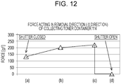
- Fig. 12 shows the magnitude of a force in the -X direction that acts upon the collecting toner container 114 from the first arm 806.
- (a) to (d) indicated along the horizontal axis of Fig. 12 corresponds to Figs. 11(a) to 11(d) , respectively.
- an elastic force of the spring 310 that urges the shutter 300 by stretching of the spring 310 causes a force Fa in the +Y direction to act on the second arm 807 from the shutter 113, and a force F'a corresponding to the force Fa to act upon the first flat surface 114b1 from the first contact portion 806a of the first arm 806.
- a force F'a ⁇ cos ⁇ a acts in the -X direction upon the collecting toner container 114 in the state shown in Fig. 11(a) .
- a force of approximately 130 gf acts in the -X direction upon the collecting toner container 114 in the state shown in Fig. 11(a) .
- a force F'b ⁇ cos ⁇ b acts upon the collecting toner container 114 in the -X direction and, in the state shown in Fig. 11(c) , a force F'c ⁇ cos ⁇ c acts upon the collecting toner container 114 in the -X direction.
- a force of approximately 200 gf acts upon the collecting toner container 114 in the -X direction and, in the state shown in Fig. 11(c) , a force of approximately 210 gf acts upon the collecting toner container 114 in the -X direction.
- the second flat surface 114b2 and the contact portion 806a of the first arm 806 contact each other, the force that acts upon the collecting toner container 114 in the -X direction is 0 gf. Therefore, in Fig. 11(d) , the collecting toner container 114 is in a state in which it is unlikely to fall from the toner container holding mechanism 115.
- the second flat surface 114b2 need not be necessarily parallel to the X axis. It is desirable that the inclination angle of the second flat surface 114b2 be smaller than the inclination angle of the first flat surface 114b1 with respect to the X axis.
- the contact portion 806a need not be formed of only two flat surfaces, such as the first flat surface 114b1 and the second flat surface 114b2.
- the contact portion 806a may be formed of three or more flat surfaces.
- the shape of the contact portion 806a may be curved so that the inclination angle becomes a gentle angle in the -X direction with respect to an imaginary plane.
- the recess 218b is formed in the opposing surface 218g of the cover 218 opposing the shutter 300, and the spring 310 for sliding the shutter 300 is connected to the connection portion 218e at the recess 218b. Therefore, it is possible to prevent the size of the structure of the shutter 300 and that of the light scanning device from increasing.
Landscapes
- Physics & Mathematics (AREA)
- General Physics & Mathematics (AREA)
- Optics & Photonics (AREA)
- Electrophotography Configuration And Component (AREA)
- Mechanical Optical Scanning Systems (AREA)
- Laser Beam Printer (AREA)
- Facsimile Scanning Arrangements (AREA)
- Exposure Or Original Feeding In Electrophotography (AREA)
- Color Electrophotography (AREA)
Claims (11)
- Bilderzeugungsvorrichtung, umfassend:eine erste Lichtquelle (202M), die konfiguriert ist zum Emittieren eines ersten Lichtstrahls zum Belichten eines ersten Fotoleiters (102M);eine zweite Lichtquelle (202C), die konfiguriert ist zum Emittieren eines zweiten Lichtstrahls zum Belichten eines zweiten Fotoleiters (102C);ein rotierender Polygonspiegel (203), der konfiguriert ist, den ersten und zweiten Lichtstrahl derart umzulenken, dass der erste Lichtstrahl den ersten Fotoleiter abtastet und der zweite Lichtstrahl den zweiten Fotoleiter abtastet, wobei der rotierende Polygonspiegel den ersten Lichtstrahl und den zweiten Lichtstrahl zu gegenüberliegenden Seiten mit dem rotierende Polygonspiegel dazwischen umlenkt;ein Optikgehäuse (201), in dem die erste Lichtquelle, die zweite Lichtquelle und der rotierende Polygonspiegel angeordnet sind;eine Abdeckung (218), die konfiguriert ist zum Abdecken des Optikgehäuses, wobei die Abdeckung ein erstes transparentes Fenster (224) und ein zweites transparentes Fenster (225) enthält, die auf gegenüberliegenden Seiten mit dem rotierenden Polygonspiegel dazwischen angeordnet sind, wobei der durch den rotierenden Polygonspiegel umgelenkte erste Lichtstrahl das erste transparente Fenster durchdringt und der durch den rotierenden Polygonspiegel umgelenkte zweite Lichtstrahl das zweite transparente Fenster durchdringt;einen Verschluss (300), der der Abdeckung gegenüber angeordnet ist, wobei der Verschluss derart gleitet, um sich zwischen einer Position, an der das erste transparente Fenster und das zweite transparente Fenster abgedeckt sind und einer Position, die von einem Lichtweg des das erste transparente Fenster durchdringenden ersten Lichtstrahls und von einem Lichtweg des das zweite transparente Fenster durchdringenden zweiten Lichtstrahls versetzt ist, hin- und herzubewegen; undeinen Verschlussbewegungsmechanismus (807, 310), der eine Drängeinrichtung (807) und eine Feder (310) enthält, wobei die Drängeinrichtung den Verschluss durch Drängen des Verschlusses in eine Gleitbewegung versetzt, wobei die Feder mit dem Verschluss und der Abdeckung verbunden ist und derart geformt ist, dass eine Federkraft, die den Verschluss in eine einer Drängrichtung der Drängeinrichtung entgegengesetzte Richtung drängt, sich erhöht, wenn eine Bewegungsmenge des durch die Drängeinrichtung gedrängten Verschlusses sich erhöht, und den Verschluss durch die Federkraft in eine Gleitbewegung in die entgegengesetzte Richtung versetzt,gekennzeichnet durch eine Vertiefung (218b), die an einer gegenüberliegenden Fläche der Abdeckung, dem Verschluss gegenüberliegend, und an einer Seite gegenüber der ersten Lichtquelle und der zweiten Lichtquelle mit dem rotierenden Polygonspiegel dazwischen vorgesehen ist, wobei die Vertiefung zu einer Innenseite des durch die Abdeckung abgedeckten Optikgehäuses hin an einer Stelle zwischen dem ersten transparenten Fenster und dem zweiten transparenten Fenster vertieft ist und wobei ein Verbindungsabschnitt (218e), mit dem die mit dem Verschluss verbundene Feder verbunden ist, an der Vertiefung vorgesehen ist.
- Bilderzeugungsvorrichung nach Anspruch 1, ferner umfassend:eine dritte Lichtquelle (2O2Y), die konfiguriert ist zum Emittieren eines dritten Lichtstrahls zum Belichten eines dritten Fotoleiters (102Y), der in Bezug auf den rotierenden Polygonspiegel auf derselben Seite wie der erste Fotoleiter und weiter weg vom rotierenden Polygonspiegel als der erste Fotoleiter angeordnet ist; undeine vierte Lichtquelle (202Bk), die konfiguriert ist zum Emittieren eines vierten Lichtstrahls zum Belichten eines vierten Fotoleiters (102Bk), der in Bezug auf den rotierenden Polygonspiegel auf derselben Seite wie der zweite Fotoleiter und weiter weg vom rotierenden Polygonspiegel als der zweite Fotoleiter angeordnet ist,wobei der dritte Lichtstrahl durch den rotierenden Polygonspiegel zu einer Seite umgelenkt wird, die dieselbe Seite ist, zu der der erste Lichtstrahl umgelenkt wird, sodass der dritte Lichtstrahl den dritten Fotoleiter abtastet,wobei der vierte Lichtstrahl durch den rotierenden Polygonspiegel zu einer Seite umgelenkt wird, die dieselbe Seite ist, zu der der zweite Lichtstrahl umgelenkt wird, sodass der vierte Lichtstrahl den vierten Fotoleiter abtastet,
undwobei die Abdeckung ein drittes transparentes Fenster (223) und ein viertes transparentes Fenster enthält (226), wobei das dritte transparente Fenster weiter weg vom rotierenden Polygonspiegel als das erste transparente Fenster angeordnet ist und von dem durch den rotierenden Polygonspiegel umgelenkten dritten Lichtstrahl durchdrungen wird, und das vierte transparente Fenster weiter weg vom rotierenden Polygonspiegel als das zweite transparente Fenster angeordnet ist und von dem durch den rotierenden Polygonspiegel umgelenkten vierten Lichtstrahl durchdrungen wird. - Bilderzeugungsvorrichtung nach Anspruch 1, wobei aus Sicht von einer Rotationsachsenrichtung des rotierenden Polygonspiegels die Vertiefung an einer Position vorgesehen ist, an der die Lichtwege des durch den rotierenden Polygonspiegel umgelenkten ersten und zweiten Lichtstrahls nicht blockiert werden.
- Bilderzeugungsvorrichtung nach Anspruch 2, wobei aus Sicht von einer Rotationsachsenrichtung des rotierenden Polygonspiegels die Vertiefung an einer Position vorgesehen ist, an der die Lichtwege des durch den rotierenden Polygonspiegel umgelenkten ersten und zweiten Lichtstrahls und Lichtwege des durch den rotierenden Polygonspiegel umgelenkten dritten und vierten Lichtstrahls nicht blockiert werden.
- Bilderzeugungsvorrichtung nach einem der Ansprüche 1 bis 4, wobei ein Kontaktabschnitt (807a) zwischen dem Verschluss und der den Verschluss drängenden Drängeinrichtung, ein Verbindungsabschnitt (304) zwischen dem Verschluss und der Feder und der Verbindungsabschnitt (218e) zwischen der Abdeckung und der Feder im Wesentlichen auf einer geraden Linie positioniert sind.
- Bilderzeugungsvorrichtung nach Anspruch 2 oder 4, ferner umfassend einen Führungsmechanismus (218e, 302), der einen Vorsprung (218c) und einen Einfügungsabschnitt (302) enthält, wobei der Vorsprung an der gegenüberliegenden Fläche an einer Stelle zwischen dem ersten transparenten Fenster und dem dritten transparenten Fenster der Abdeckung vorgesehen ist, der Einfügungsabschnitt am Verschluss vorgesehen ist und den Vorsprung empfängt, und der Führungsmechanismus eine Gleitrichtung des Verschlusses durch den in den Einfügungsabschnitt eingefügten Vorsprung einschränkt,
wobei ein Kontaktabschnitt (807a) zwischen dem Verschluss und der den Verschluss drängenden Drängeinrichtung, ein Verbindungsabschnitt (304) zwischen dem Verschluss und der Feder, der Verbindungsabschnitt (218e) zwischen der Abdeckung und der Feder und der Vorsprung im Wesentlichen auf einer geraden Linie positioniert sind. - Bilderzeugungsvorrichtung nach Anspruch 2 oder 4, ferner umfassend einen Führungsmechanismus (218c, 218d, 302, 303), der einen ersten Vorsprung (218c), einen zweiten Vorsprung (218d), einen ersten Einfügungsabschnitt (302) und einen zweiten Einfügungsabschnitt (303) enthält, wobei der erste Vorsprung an der gegenüberliegenden Fläche an einer Stelle zwischen dem ersten transparenten Fenster und dem dritten transparenten Fenster der Abdeckung vorgesehen ist, der zweite Vorsprang an der gegenüberliegenden Seite der Abdeckung an einer Stelle zwischen dem zweiten transparenten Fenster und dem vierten transparenten Fenster vorgesehen ist, der erste Einfügungsabschnitt am Verschluss vorgesehen ist und den ersten Vorsprung empfängt, der zweite Einfügungsabschnitt am Verschluss vorgesehen ist und den zweiten Vorsprung empfängt, und der Führungsmechanismus eine Gleitrichtung des Verschlusses durch den in den ersten Einfügungsabschnitt eingefügten ersten Vorsprung und den in den zweiten Einfügungsabschnitt eingefügten zweiten Vorsprung einschränkt,
wobei ein Kontaktabschnitt (807a) zwischen dem Verschluss und der den Verschluss drängenden Drängeinrichtung, ein Verbindungsabschnitt (304) zwischen dem Verschluss und der Feder, der Verbindungsabschnitt (218e) zwischen der Abdeckung und der Feder, der erste Vorsprung und der zweite Vorsprung im Wesentlichen auf einer geraden Linie positioniert sind. - Bilderzeugungsvorrichtung nach Anspruch 1 oder 2, ferner umfassend einen Führungsmechanismus (218c, 302), der einen ersten Vorsprung (218c) und einen Einfügungsabschnitt enthält, wobei der Vorsprung (302) am Verschluss vorgesehen ist, der Einfügungsabschnitt an der gegenüberliegenden Fläche der Abdeckung an einer Stelle zwischen dem ersten transparenten Fenster und dem dritten transparenten Fenster der Abdeckung vorgesehen ist und der Einfügungsabschnitt den Vorsprung empfängt, und der Führungsmechanismus eine Gleitrichtung des Verschlusses durch den in den Einfügungsabschnitt eingefügten Vorsprung einschränkt.
- Bilderzeugungsvorrichtung nach Anspruch 2 oder 4, ferner umfassend einen Führungsmechanismus (218c, 302), der einen Vorsprung (218c) und einen Einfügungsabschnitt (302) enthält, wobei der Vorsprung am Verschluss vorgesehen ist, der Einfügungsabschnitt an der gegenüberliegenden Fläche an einer Stelle zwischen dem ersten transparenten Fenster und dem dritten transparenten Fenster der Abdeckung vorgesehen ist und der Einfügungsabschnitt den Vorsprung empfängt, und der Führungsmechanismus eine Gleitrichtung des Verschlusses durch den in den Einfügungsabschnitt eingefügten Vorsprung einschränkt,
wobei ein Kontaktabschnitt (807a) zwischen dem Verschluss und der den Verschluss drängenden Drängeinrichtung, ein Verbindungsabschnitt (304) zwischen dem Verschluss und der Feder, der Verbindungsabschnitt (218e) zwischen der Abdeckung und der Feder und der Vorsprung im Wesentlichen auf einer geraden Linie positioniert sind. - Bilderzeugungsvorrichtung nach Anspruch 2 oder 4, ferner umfassend einen Führungsmechanismus, der einen ersten Vorsprung, einen zweiten Vorsprung, einen ersten Einfügungsabschnitt und einen zweiten Einfügungsabschnitt enthält, wobei der erste und der zweite Vorsprung am Verschluss vorgesehen sind, der erste Einfügungsabschnitt an der gegenüberliegenden Fläche an einer Stelle zwischen dem ersten transparenten Fenster und dem dritten transparenten Fenster der Abdeckung vorgesehen ist und der erste Einfügungsabschnitt den ersten Vorsprung empfängt, der zweite Einfügungsabschnitt an der gegenüberliegenden Fläche an einer Stelle zwischen dem zweiten transparenten Fenster und dem vierten transparenten Fenster der Abdeckung vorgesehen ist und der zweite Einfügungsabschnitt den zweiten Vorsprung empfängt, wobei der Führungsmechanismus eine Gleitrichtung des Verschlusses durch den in den ersten Einfügungsabschnitt eingefügten ersten Vorsprung und den in den zweiten Einfügungsabschnitt eingefügten zweiten Vorsprung einschränkt,
wobei ein Kontaktabschnitt zwischen dem Verschluss und der den Verschluss drängenden Drängeinrichtung, ein Verbindungsabschnitt zwischen dem Verschluss und der Feder, der Verbindungsabschnitt zwischen der Abdeckung und der Feder, der erste Vorsprung und der zweite Vorsprung im Wesentlichen auf einer geraden Linie positioniert sind. - Bilderzeugungsvorrichtung nach Anspruch 1, wobei in einer Rotationsachsenrichtung des Polygonspiegels (203) eine untere Fläche (218f) an der Vertiefung (218b) der Abdeckung (218) näher an einer unteren Fläche des Optikgehäuses (201) vorgesehen ist als die transparenten Fenster (224, 225).
Applications Claiming Priority (1)
| Application Number | Priority Date | Filing Date | Title |
|---|---|---|---|
| PCT/JP2012/083847 WO2014102958A1 (ja) | 2012-12-27 | 2012-12-27 | 画像形成装置 |
Publications (3)
| Publication Number | Publication Date |
|---|---|
| EP2942670A1 EP2942670A1 (de) | 2015-11-11 |
| EP2942670A4 EP2942670A4 (de) | 2016-09-14 |
| EP2942670B1 true EP2942670B1 (de) | 2020-09-16 |
Family
ID=51016737
Family Applications (1)
| Application Number | Title | Priority Date | Filing Date |
|---|---|---|---|
| EP12890680.7A Active EP2942670B1 (de) | 2012-12-27 | 2012-12-27 | Bilderzeugungsvorrichtung |
Country Status (6)
| Country | Link |
|---|---|
| US (2) | US9207559B2 (de) |
| EP (1) | EP2942670B1 (de) |
| JP (1) | JP6012765B2 (de) |
| CN (1) | CN104885019B (de) |
| BR (1) | BR112015014234A2 (de) |
| WO (1) | WO2014102958A1 (de) |
Families Citing this family (4)
| Publication number | Priority date | Publication date | Assignee | Title |
|---|---|---|---|---|
| CN104885019B (zh) * | 2012-12-27 | 2017-12-08 | 佳能株式会社 | 成像设备 |
| JP6074262B2 (ja) * | 2012-12-27 | 2017-02-01 | キヤノン株式会社 | 画像形成装置 |
| JP6370060B2 (ja) * | 2014-02-27 | 2018-08-08 | キヤノン株式会社 | 画像形成装置 |
| JP7218127B2 (ja) | 2018-08-31 | 2023-02-06 | キヤノン株式会社 | レンズ装置およびカメラシステム |
Family Cites Families (9)
| Publication number | Priority date | Publication date | Assignee | Title |
|---|---|---|---|---|
| JP4414933B2 (ja) * | 2004-06-30 | 2010-02-17 | 株式会社リコー | 光書き込み装置及び画像形成装置 |
| CN100351711C (zh) * | 2004-06-30 | 2007-11-28 | 株式会社理光 | 光写入装置及图像形成装置 |
| US7872664B2 (en) * | 2005-09-26 | 2011-01-18 | Ricoh Company, Limited | Optical scanning device including shutter member that closes or opens an emission window and image forming apparatus including the optical scanning device |
| JP4846317B2 (ja) * | 2005-09-26 | 2011-12-28 | 株式会社リコー | シャッターおよび画像形成装置 |
| JP4871577B2 (ja) * | 2005-11-30 | 2012-02-08 | 株式会社リコー | 光走査装置および画像形成装置 |
| KR20080010970A (ko) * | 2006-07-28 | 2008-01-31 | 삼성전자주식회사 | 광주사장치와 이를 구비하는 화상형성장치 및 광주사장치의 청소장치 |
| KR101111902B1 (ko) * | 2007-02-06 | 2012-02-14 | 삼성전자주식회사 | 광주사창 클리닝셔터를 갖는 광주사모듈 및 이를 포함하는화상형성장치 |
| JP5033548B2 (ja) * | 2007-09-10 | 2012-09-26 | 株式会社リコー | 光書込装置及び画像形成装置 |
| CN104885019B (zh) * | 2012-12-27 | 2017-12-08 | 佳能株式会社 | 成像设备 |
-
2012
- 2012-12-27 CN CN201280078010.6A patent/CN104885019B/zh active Active
- 2012-12-27 BR BR112015014234A patent/BR112015014234A2/pt not_active Application Discontinuation
- 2012-12-27 JP JP2014553959A patent/JP6012765B2/ja active Active
- 2012-12-27 EP EP12890680.7A patent/EP2942670B1/de active Active
- 2012-12-27 WO PCT/JP2012/083847 patent/WO2014102958A1/ja not_active Ceased
-
2013
- 2013-12-23 US US14/138,874 patent/US9207559B2/en not_active Expired - Fee Related
-
2015
- 2015-11-03 US US14/931,712 patent/US9618876B2/en active Active
Non-Patent Citations (1)
| Title |
|---|
| None * |
Also Published As
| Publication number | Publication date |
|---|---|
| US20140184719A1 (en) | 2014-07-03 |
| WO2014102958A1 (ja) | 2014-07-03 |
| CN104885019A (zh) | 2015-09-02 |
| EP2942670A1 (de) | 2015-11-11 |
| CN104885019B (zh) | 2017-12-08 |
| JPWO2014102958A1 (ja) | 2017-01-12 |
| BR112015014234A2 (pt) | 2017-07-11 |
| US9207559B2 (en) | 2015-12-08 |
| US9618876B2 (en) | 2017-04-11 |
| WO2014102958A9 (ja) | 2015-04-23 |
| JP6012765B2 (ja) | 2016-10-25 |
| US20160124339A1 (en) | 2016-05-05 |
| EP2942670A4 (de) | 2016-09-14 |
Similar Documents
| Publication | Publication Date | Title |
|---|---|---|
| US8428474B2 (en) | Developing device, process cartridge, and image forming apparatus | |
| US9933725B2 (en) | Developing device, process cartridge, and electrophotographic image forming apparatus | |
| EP2942670B1 (de) | Bilderzeugungsvorrichtung | |
| US7187886B2 (en) | Image forming apparatus having a securing member to secure an image forming unit to a housing body | |
| JP5397328B2 (ja) | 画像形成装置 | |
| JP6074262B2 (ja) | 画像形成装置 | |
| JP6080625B2 (ja) | 画像形成装置 | |
| EP3709096A1 (de) | In einer bilderzeugungsvorrichtung mit optischem druckkopf verwendetes reinigungselement und bilderzeugungsvorrichtung mit optischem druckkopf | |
| US12072667B2 (en) | Cartridge and image forming apparatus | |
| JP6173147B2 (ja) | 光走査装置及び画像形成装置 | |
| JP6021635B2 (ja) | 画像形成装置 | |
| JP6370060B2 (ja) | 画像形成装置 | |
| JP6266066B2 (ja) | 画像形成装置 | |
| JP6261698B2 (ja) | 画像形成装置 | |
| JP2014126828A (ja) | 画像形成装置 | |
| JP6188501B2 (ja) | 光走査装置及び画像形成装置 | |
| JP6659128B2 (ja) | 画像形成装置 | |
| JP2003149895A (ja) | 画像形成装置 | |
| JP2016118764A (ja) | 画像形成装置および光学走査装置 |
Legal Events
| Date | Code | Title | Description |
|---|---|---|---|
| PUAI | Public reference made under article 153(3) epc to a published international application that has entered the european phase |
Free format text: ORIGINAL CODE: 0009012 |
|
| 17P | Request for examination filed |
Effective date: 20150727 |
|
| AK | Designated contracting states |
Kind code of ref document: A1 Designated state(s): AL AT BE BG CH CY CZ DE DK EE ES FI FR GB GR HR HU IE IS IT LI LT LU LV MC MK MT NL NO PL PT RO RS SE SI SK SM TR |
|
| AX | Request for extension of the european patent |
Extension state: BA ME |
|
| DAX | Request for extension of the european patent (deleted) | ||
| A4 | Supplementary search report drawn up and despatched |
Effective date: 20160818 |
|
| RIC1 | Information provided on ipc code assigned before grant |
Ipc: H04N 1/113 20060101ALI20160811BHEP Ipc: G02B 26/10 20060101ALI20160811BHEP Ipc: G03G 15/00 20060101ALI20160811BHEP Ipc: G03G 15/01 20060101ALI20160811BHEP Ipc: G03G 15/043 20060101ALI20160811BHEP Ipc: B41J 2/44 20060101ALI20160811BHEP Ipc: G03G 15/04 20060101AFI20160811BHEP Ipc: G03G 21/16 20060101ALI20160811BHEP |
|
| GRAP | Despatch of communication of intention to grant a patent |
Free format text: ORIGINAL CODE: EPIDOSNIGR1 |
|
| STAA | Information on the status of an ep patent application or granted ep patent |
Free format text: STATUS: GRANT OF PATENT IS INTENDED |
|
| INTG | Intention to grant announced |
Effective date: 20200428 |
|
| GRAS | Grant fee paid |
Free format text: ORIGINAL CODE: EPIDOSNIGR3 |
|
| GRAA | (expected) grant |
Free format text: ORIGINAL CODE: 0009210 |
|
| STAA | Information on the status of an ep patent application or granted ep patent |
Free format text: STATUS: THE PATENT HAS BEEN GRANTED |
|
| AK | Designated contracting states |
Kind code of ref document: B1 Designated state(s): AL AT BE BG CH CY CZ DE DK EE ES FI FR GB GR HR HU IE IS IT LI LT LU LV MC MK MT NL NO PL PT RO RS SE SI SK SM TR |
|
| REG | Reference to a national code |
Ref country code: GB Ref legal event code: FG4D |
|
| REG | Reference to a national code |
Ref country code: CH Ref legal event code: EP |
|
| REG | Reference to a national code |
Ref country code: DE Ref legal event code: R096 Ref document number: 602012072387 Country of ref document: DE |
|
| REG | Reference to a national code |
Ref country code: IE Ref legal event code: FG4D |
|
| REG | Reference to a national code |
Ref country code: AT Ref legal event code: REF Ref document number: 1314694 Country of ref document: AT Kind code of ref document: T Effective date: 20201015 |
|
| PG25 | Lapsed in a contracting state [announced via postgrant information from national office to epo] |
Ref country code: HR Free format text: LAPSE BECAUSE OF FAILURE TO SUBMIT A TRANSLATION OF THE DESCRIPTION OR TO PAY THE FEE WITHIN THE PRESCRIBED TIME-LIMIT Effective date: 20200916 Ref country code: FI Free format text: LAPSE BECAUSE OF FAILURE TO SUBMIT A TRANSLATION OF THE DESCRIPTION OR TO PAY THE FEE WITHIN THE PRESCRIBED TIME-LIMIT Effective date: 20200916 Ref country code: SE Free format text: LAPSE BECAUSE OF FAILURE TO SUBMIT A TRANSLATION OF THE DESCRIPTION OR TO PAY THE FEE WITHIN THE PRESCRIBED TIME-LIMIT Effective date: 20200916 Ref country code: NO Free format text: LAPSE BECAUSE OF FAILURE TO SUBMIT A TRANSLATION OF THE DESCRIPTION OR TO PAY THE FEE WITHIN THE PRESCRIBED TIME-LIMIT Effective date: 20201216 Ref country code: BG Free format text: LAPSE BECAUSE OF FAILURE TO SUBMIT A TRANSLATION OF THE DESCRIPTION OR TO PAY THE FEE WITHIN THE PRESCRIBED TIME-LIMIT Effective date: 20201216 Ref country code: GR Free format text: LAPSE BECAUSE OF FAILURE TO SUBMIT A TRANSLATION OF THE DESCRIPTION OR TO PAY THE FEE WITHIN THE PRESCRIBED TIME-LIMIT Effective date: 20201217 |
|
| REG | Reference to a national code |
Ref country code: AT Ref legal event code: MK05 Ref document number: 1314694 Country of ref document: AT Kind code of ref document: T Effective date: 20200916 |
|
| REG | Reference to a national code |
Ref country code: NL Ref legal event code: MP Effective date: 20200916 |
|
| PG25 | Lapsed in a contracting state [announced via postgrant information from national office to epo] |
Ref country code: RS Free format text: LAPSE BECAUSE OF FAILURE TO SUBMIT A TRANSLATION OF THE DESCRIPTION OR TO PAY THE FEE WITHIN THE PRESCRIBED TIME-LIMIT Effective date: 20200916 Ref country code: LV Free format text: LAPSE BECAUSE OF FAILURE TO SUBMIT A TRANSLATION OF THE DESCRIPTION OR TO PAY THE FEE WITHIN THE PRESCRIBED TIME-LIMIT Effective date: 20200916 |
|
| REG | Reference to a national code |
Ref country code: LT Ref legal event code: MG4D |
|
| PG25 | Lapsed in a contracting state [announced via postgrant information from national office to epo] |
Ref country code: CZ Free format text: LAPSE BECAUSE OF FAILURE TO SUBMIT A TRANSLATION OF THE DESCRIPTION OR TO PAY THE FEE WITHIN THE PRESCRIBED TIME-LIMIT Effective date: 20200916 Ref country code: EE Free format text: LAPSE BECAUSE OF FAILURE TO SUBMIT A TRANSLATION OF THE DESCRIPTION OR TO PAY THE FEE WITHIN THE PRESCRIBED TIME-LIMIT Effective date: 20200916 Ref country code: RO Free format text: LAPSE BECAUSE OF FAILURE TO SUBMIT A TRANSLATION OF THE DESCRIPTION OR TO PAY THE FEE WITHIN THE PRESCRIBED TIME-LIMIT Effective date: 20200916 Ref country code: SM Free format text: LAPSE BECAUSE OF FAILURE TO SUBMIT A TRANSLATION OF THE DESCRIPTION OR TO PAY THE FEE WITHIN THE PRESCRIBED TIME-LIMIT Effective date: 20200916 Ref country code: NL Free format text: LAPSE BECAUSE OF FAILURE TO SUBMIT A TRANSLATION OF THE DESCRIPTION OR TO PAY THE FEE WITHIN THE PRESCRIBED TIME-LIMIT Effective date: 20200916 Ref country code: LT Free format text: LAPSE BECAUSE OF FAILURE TO SUBMIT A TRANSLATION OF THE DESCRIPTION OR TO PAY THE FEE WITHIN THE PRESCRIBED TIME-LIMIT Effective date: 20200916 Ref country code: PT Free format text: LAPSE BECAUSE OF FAILURE TO SUBMIT A TRANSLATION OF THE DESCRIPTION OR TO PAY THE FEE WITHIN THE PRESCRIBED TIME-LIMIT Effective date: 20210118 |
|
| PG25 | Lapsed in a contracting state [announced via postgrant information from national office to epo] |
Ref country code: PL Free format text: LAPSE BECAUSE OF FAILURE TO SUBMIT A TRANSLATION OF THE DESCRIPTION OR TO PAY THE FEE WITHIN THE PRESCRIBED TIME-LIMIT Effective date: 20200916 Ref country code: IS Free format text: LAPSE BECAUSE OF FAILURE TO SUBMIT A TRANSLATION OF THE DESCRIPTION OR TO PAY THE FEE WITHIN THE PRESCRIBED TIME-LIMIT Effective date: 20210116 Ref country code: ES Free format text: LAPSE BECAUSE OF FAILURE TO SUBMIT A TRANSLATION OF THE DESCRIPTION OR TO PAY THE FEE WITHIN THE PRESCRIBED TIME-LIMIT Effective date: 20200916 Ref country code: AT Free format text: LAPSE BECAUSE OF FAILURE TO SUBMIT A TRANSLATION OF THE DESCRIPTION OR TO PAY THE FEE WITHIN THE PRESCRIBED TIME-LIMIT Effective date: 20200916 Ref country code: AL Free format text: LAPSE BECAUSE OF FAILURE TO SUBMIT A TRANSLATION OF THE DESCRIPTION OR TO PAY THE FEE WITHIN THE PRESCRIBED TIME-LIMIT Effective date: 20200916 |
|
| REG | Reference to a national code |
Ref country code: DE Ref legal event code: R097 Ref document number: 602012072387 Country of ref document: DE |
|
| PG25 | Lapsed in a contracting state [announced via postgrant information from national office to epo] |
Ref country code: SK Free format text: LAPSE BECAUSE OF FAILURE TO SUBMIT A TRANSLATION OF THE DESCRIPTION OR TO PAY THE FEE WITHIN THE PRESCRIBED TIME-LIMIT Effective date: 20200916 |
|
| PLBE | No opposition filed within time limit |
Free format text: ORIGINAL CODE: 0009261 |
|
| STAA | Information on the status of an ep patent application or granted ep patent |
Free format text: STATUS: NO OPPOSITION FILED WITHIN TIME LIMIT |
|
| REG | Reference to a national code |
Ref country code: CH Ref legal event code: PL |
|
| 26N | No opposition filed |
Effective date: 20210617 |
|
| PG25 | Lapsed in a contracting state [announced via postgrant information from national office to epo] |
Ref country code: SI Free format text: LAPSE BECAUSE OF FAILURE TO SUBMIT A TRANSLATION OF THE DESCRIPTION OR TO PAY THE FEE WITHIN THE PRESCRIBED TIME-LIMIT Effective date: 20200916 Ref country code: MC Free format text: LAPSE BECAUSE OF FAILURE TO SUBMIT A TRANSLATION OF THE DESCRIPTION OR TO PAY THE FEE WITHIN THE PRESCRIBED TIME-LIMIT Effective date: 20200916 Ref country code: DK Free format text: LAPSE BECAUSE OF FAILURE TO SUBMIT A TRANSLATION OF THE DESCRIPTION OR TO PAY THE FEE WITHIN THE PRESCRIBED TIME-LIMIT Effective date: 20200916 |
|
| REG | Reference to a national code |
Ref country code: BE Ref legal event code: MM Effective date: 20201231 |
|
| PG25 | Lapsed in a contracting state [announced via postgrant information from national office to epo] |
Ref country code: LU Free format text: LAPSE BECAUSE OF NON-PAYMENT OF DUE FEES Effective date: 20201227 Ref country code: FR Free format text: LAPSE BECAUSE OF NON-PAYMENT OF DUE FEES Effective date: 20201231 Ref country code: IE Free format text: LAPSE BECAUSE OF NON-PAYMENT OF DUE FEES Effective date: 20201227 Ref country code: IT Free format text: LAPSE BECAUSE OF FAILURE TO SUBMIT A TRANSLATION OF THE DESCRIPTION OR TO PAY THE FEE WITHIN THE PRESCRIBED TIME-LIMIT Effective date: 20200916 |
|
| PG25 | Lapsed in a contracting state [announced via postgrant information from national office to epo] |
Ref country code: LI Free format text: LAPSE BECAUSE OF NON-PAYMENT OF DUE FEES Effective date: 20201231 Ref country code: CH Free format text: LAPSE BECAUSE OF NON-PAYMENT OF DUE FEES Effective date: 20201231 |
|
| PG25 | Lapsed in a contracting state [announced via postgrant information from national office to epo] |
Ref country code: TR Free format text: LAPSE BECAUSE OF FAILURE TO SUBMIT A TRANSLATION OF THE DESCRIPTION OR TO PAY THE FEE WITHIN THE PRESCRIBED TIME-LIMIT Effective date: 20200916 Ref country code: MT Free format text: LAPSE BECAUSE OF FAILURE TO SUBMIT A TRANSLATION OF THE DESCRIPTION OR TO PAY THE FEE WITHIN THE PRESCRIBED TIME-LIMIT Effective date: 20200916 Ref country code: CY Free format text: LAPSE BECAUSE OF FAILURE TO SUBMIT A TRANSLATION OF THE DESCRIPTION OR TO PAY THE FEE WITHIN THE PRESCRIBED TIME-LIMIT Effective date: 20200916 |
|
| PG25 | Lapsed in a contracting state [announced via postgrant information from national office to epo] |
Ref country code: MK Free format text: LAPSE BECAUSE OF FAILURE TO SUBMIT A TRANSLATION OF THE DESCRIPTION OR TO PAY THE FEE WITHIN THE PRESCRIBED TIME-LIMIT Effective date: 20200916 |
|
| PG25 | Lapsed in a contracting state [announced via postgrant information from national office to epo] |
Ref country code: BE Free format text: LAPSE BECAUSE OF NON-PAYMENT OF DUE FEES Effective date: 20201231 |
|
| PGFP | Annual fee paid to national office [announced via postgrant information from national office to epo] |
Ref country code: DE Payment date: 20251126 Year of fee payment: 14 |
|
| PGFP | Annual fee paid to national office [announced via postgrant information from national office to epo] |
Ref country code: GB Payment date: 20251120 Year of fee payment: 14 |