EP2943003A1 - Kleinzelliger Basisstationseinsatz in zellularen Netzwerken - Google Patents
Kleinzelliger Basisstationseinsatz in zellularen Netzwerken Download PDFInfo
- Publication number
- EP2943003A1 EP2943003A1 EP14305677.8A EP14305677A EP2943003A1 EP 2943003 A1 EP2943003 A1 EP 2943003A1 EP 14305677 A EP14305677 A EP 14305677A EP 2943003 A1 EP2943003 A1 EP 2943003A1
- Authority
- EP
- European Patent Office
- Prior art keywords
- small cell
- antenna
- performance
- indication
- antenna patterns
- Prior art date
- Legal status (The legal status is an assumption and is not a legal conclusion. Google has not performed a legal analysis and makes no representation as to the accuracy of the status listed.)
- Granted
Links
Images




Classifications
-
- H—ELECTRICITY
- H04—ELECTRIC COMMUNICATION TECHNIQUE
- H04W—WIRELESS COMMUNICATION NETWORKS
- H04W24/00—Supervisory, monitoring or testing arrangements
- H04W24/02—Arrangements for optimising operational condition
-
- H—ELECTRICITY
- H04—ELECTRIC COMMUNICATION TECHNIQUE
- H04W—WIRELESS COMMUNICATION NETWORKS
- H04W16/00—Network planning, e.g. coverage or traffic planning tools; Network deployment, e.g. resource partitioning or cells structures
- H04W16/24—Cell structures
- H04W16/28—Cell structures using beam steering
-
- H—ELECTRICITY
- H04—ELECTRIC COMMUNICATION TECHNIQUE
- H04W—WIRELESS COMMUNICATION NETWORKS
- H04W16/00—Network planning, e.g. coverage or traffic planning tools; Network deployment, e.g. resource partitioning or cells structures
- H04W16/24—Cell structures
- H04W16/32—Hierarchical cell structures
Definitions
- the present invention relates to the field of wireless communication networks and in particular networks comprising small cells arranged to provide additional local capacity.
- Wireless communication networks are known and are generally arranged in a cellular system where radio coverage is provided to user equipment, for example, mobile telephones, by geographical area. Those geographical areas of radio coverage are known as cells. Abase station is located in each geographical area to provide the required radio coverage. User equipment in the area served by a base station receives information and data from that base station and transmits information and data to that base station. There is an ever increasing demand for wireless multimedia services and this is driving strong growth in wireless data traffic. In order to accommodate this, various strategies such as the use of small cells are being considered.
- Small cells have the same or similar capabilities as macro cells but have a much reduced geographical coverage. Such smaller sized cells are sometimes referred to as micro cells, pico cells or femto cells. Deployment of small cells in a wireless communication network can assist a network in relation to handling capacity in high traffic areas, for example, so-called hot spot areas. An ability to offload traffic to a small cell or cells located in a high traffic area of a network may be particularly useful to a network operator.
- small cells may operate on a dedicated frequency
- co-channel operation on the same frequency as an existing macrocellular network is generally preferable despite the challenges.
- a small cell can add capacity to a macrocell but will also add interference and may increase unnecessary handovers, thus the placement of small cells should be carefully controlled.
- operators may not have either the flexibility or the knowledge to locate small cells in the most advantageous positions.
- the lack of deployment flexibility arises from the fact that small cells require backhaul and power supply and these may only be available in limited locations.
- the lack of knowledge is due to a lack of accurate traffic map for most networks.
- a first aspect of the present invention provides a method of improving a performance of a cellular network, said cellular network comprising a small cell base station providing radio coverage within a small cell, said small cell base station comprising at least one antenna operable to provide radio coverage in one of a plurality of antenna patterns, said method comprising: an exploration stage comprising measuring at least one indication of a performance of said small cell for at least some of said plurality of antenna patterns, said indication of said performance of said small cell comprises at least one of: traffic offload, interference impact and user equipment mobility; and an exploitation stage comprising selecting one of said plurality of antenna patterns in dependence on said measured at least one indication of small cell performance and providing said small cell radio coverage using said at least one antenna configured to generate said selected antenna pattern.
- the use of at least one antenna configured to provide antenna patterns that can be used to control the area of coverage of the small cell.
- the antenna or radiation pattern of an antenna refers to the directional or angular dependence of the strength of the radio waves or radio signals emitted from the antenna. In effect the antenna pattern provides a geographical region into which such waves are emitted with a certain field strength or up to a certain power loss and a corresponding region in which such radio signals can be effectively received.
- An exploration stage is used to determine the effect of the antenna pattern on performance, and this allows an antenna pattern that provides an improved performance to be selected.
- at least one indication of performance is measured for each antenna pattern, the indication of performance being at least one of, traffic offload to the small cell, interference impact of the small cell or the mobility of users in the area of small cell coverage.
- the proposed method uses the flexibility of different antenna patterns at small cell base-stations to improve the flexibility of small cell deployment by enhancing performance and mitigating for sub-optimal small cell placement.
- Indications of performance of the small cell within the cellular network are measured for the different antenna patterns to determine which antenna pattern provides an improved performance.
- the indications of performance are at least one of offload, that is how many user equipment connect to the small cell base station, mobility, that is an indication of how fast a user moves through the small cell, small cells not providing suitable coverage for mobile users due to their small size, and interference impact which arises due to neighbouring and/or underlying cells which the signals from the small cell base station may interfere with.
- the small cell may provide coverage independently in its own geographical region
- the cellular network will comprise a macrocell base station providing radio coverage within a macrocell, the small cell lying within the macrocell.
- the performance of this cell in the cellular network will be affected by the placement of the small cell and the selection of a suitable antenna pattern to in effect move the radio coverage of the small cell and thereby mitigate for any non-optimal locating of this cell can improve performance and reduce any burden that the misplacing of the small cell may place on the system.
- said exploration stage comprises measuring traffic offload for each of said at least some of said plurality of antenna patterns, by periodically switching between said at least some of said plurality of antenna patterns and determining for each of said antenna patterns at least one of: the proportion of time during which said antenna pattern was selected that said small cell was active; and at least one of uplink and downlink normalised traffic volume for each of said antenna patterns.
- the indications of performance of the small cell is traffic offload
- this can be measured by determining for the proportion of time during which the antenna pattern was selected whether the small cell was active, that is whether it had user equipment connected to it and/ or the amount of normalised traffic volume for at least one of the uplink and the downlink channels.
- the antenna pattern that provided the most communications with user equipment or had the most user equipment connected to it can be determined and this will be an indication of the antenna pattern that produced the greatest traffic offload that is the highest number of user equipment attaching to the small cell.
- said exploration stage comprises estimating said interference impact for each of said at least some of said plurality of antenna patterns by at least one of: measuring detected energy on uplink frequencies; increasing cell extension bias and determining a number of additional users that this generates; and receiving information on pilot powers from neighbouring cells.
- the indication of performance is or includes the interference impact of the antenna pattern
- this can be determined in a number of ways. In some cases it can be determined by detecting the energy on the uplink frequencies of user equipment in the area. In this regard, communications from user equipment to underlying or neighbouring cells may be detected at the small cell and the energy of these communications maybe an indication of how close the user equipment is to the small cell and thus, an indication of the interference impact of that small cell on the user equipment.
- An alternative and/ or additional way of estimating interference impact the cell extension bias of the small cell may be increased and the number of additional users that this generates determined.
- Small cells have a low power transmitter as they only cover a small geographical region and in order to increase a number of user equipment that connect to the small cell, an extension bias may be used such that a user equipment selects the small cell even if the s power detected in the pilot signal of the small cell is lower than the macrocell.
- Increasing this cell extension bias and determining the number of additional users this causes to connect to the small cell provides an indication of how many user equipment are close to the edge of the small cell, those close to the edge becoming the additional users. This in turn is an indication of the interference impact that a particular antenna pattern has.
- An alternative way of estimating the interference impact would be to do so cooperatively with other base stations, such that information is received from neighbouring cells on the pilot powers of user equipment in their locations. This is an accurate way of determining interference impact but requires cooperation from neighbouring cells. It should be noted that neighbouring cells may be those that are adjacent to the small cells or those that cover the same area and underlie the small cell.
- said exploration stage comprises determining said mobility of user equipment by determining a number of transient sessions, , in which a timing between an inbound and outbound handover request for a user equipment is less than a predetermined time, for each of said at least some of said plurality of antenna patterns.
- the indication of performance is mobility of the user equipment within the small cell
- this may be determined by determining how many transient sessions occur within a predetermined time for each of the plurality of antenna patterns.
- Small cells only provide a geographically limited coverage and therefore mobile users will transition through these small cells in a short time and thus, it is not advantageous if they are offloaded to the small cell as the overhead of the handover will not be worth the amount of time that they are actually connected to the small cell.
- the mobility of the user equipment is also a measure of performance of the small cell base station and the network.
- said exploration stage further comprises measuring at least two of said indications of said performance of said small cell and combining said at least two indications to generate a performance indication function and using said performance indication function to select a preferred antenna pattern for use in said exploitation stage.
- indications of performance there are various indications of performance that can be measured. In some cases, more than one of them is measured and the measurements are combined to generate a performance indication function and it is that this is used to select the preferred antenna pattern. In this regard, some of the indications such as traffic offload are positive indications of performance and the higher they are the better the performance, whereas others such as mobility and interference impact have a negative impact on performance. Thus, when combining some or all of these indications to generate a performance indication function, they should be weighted depending on their importance and added or subtracted from each other depending on whether they improve or detract from performance.
- said exploration stage is completed when it has been performed for at least one of: a predetermined time and a predetermined number of measurements, said exploitation stage being performed when said exploration stage has completed.
- the exploration stage should be performed for a reasonable length of time such that a statistically significant set of measurements is received allowing a suitable antenna pattern that provides the required coverage area to be selected.
- this method selects an antenna pattern for use over a significant period of time and thus, the exploration stage should be performed for long enough to remove, or at least reduce statistical variations that occur due to perhaps temporary high loading of the system or particular random or pseudo random events. Therefore, the exploration stage is performed for a predetermined length of time or until a certain number of measurements have been taken. This predetermined time or the number of measurements may be selected to ensure a statistically significant sample is achieved.
- the method comprises during said exploitation stage, continually measuring at least one indication of performance of said small cell and in response to said indication indicating that said performance of said small cell has fallen below a predetermined level, selecting a different antenna pattern from said at least some of said plurality of antenna patterns in dependence upon said measured small cell performance.
- the exploration stage may be performed initially and then the exploitation phase performed continuously, in some cases the exploration phase may be performed again either periodically or in response to detecting a drop in performance.
- some of the performance indications may be continually measured and where it is found that the performance has fallen below a certain level, then a different antenna pattern may be selected. This predetermined level may be set as a difference between the preferred antenna pattern and the next best antenna pattern with some additional threshold. In this way, when the performance seems to have fallen below what would have been the performance of the second preferred antenna pattern then this may be a good indication to switch to this antenna pattern as the traffic may have changed and that antenna pattern may itself be the preferred one.
- said step of measuring said performance of said small cell comprises, associating said measurements of said small cell performance with a time period in which said measurement was made, and when one of said plurality of antenna patterns provides an improved small cell performance during a first time period and a further antenna pattern provides an improved small cell performance during a second time period, said exploitation stage comprises selecting said one antenna period for said first time period and said further antenna period for said second time period.
- the performance of the small cell may be measured with respect to time and where it is found that performance varies significantly with time, then one preferred antenna pattern may be selected for one time period perhaps the time period that falls during the working day, while another antenna pattern may be selected for a different time period perhaps the time period during the evening and perhaps the night.
- Allowing antenna patterns to be selected with respect to time periods recognises that for some environments traffic will change considerably during the course of 24 hours and antenna patterns that are advantageous for one time period may not be the same as those that are advantageous for another.
- said at least one antenna comprises one of: a multiple element antenna, different antenna patterns being formed by different elements of said multiple element antenna being active; and an antenna array with a switched feeder network.
- the antenna of the small cell base station maybe a single antenna with multiple elements which can be selectively connected to the input feed line such that different single elements or in some cases combinations of elements are active, while in other embodiments it may be an array of antennas which have a switched feeder network such that different ones of the antennas are fed at different times.
- said antenna comprises a multiple element antenna and said at least some of said plurality of antenna patterns of said exploration stage comprise antenna patterns generated by each of said elements of said multiple element antenna acting as a single element antenna.
- each element may be selected individually and may generate its own radiation pattern. Such an antenna will generate a directional beam. Selecting more than one antenna element will provide a less directional coverage while selecting all elements will generate a radiation pattern similar to that generated by an omni-directional antenna.
- said exploration stage further comprises determining at least one indication of small cell performance for an antenna pattern generated by at least two of said multiple elements of said antenna; wherein said step of determining said at least one indication of small cell performance for an antenna pattern generated by at least two of said multiple elements of said antenna, comprises one of: estimating said at least one indication from said measured at least one indication for antenna patterns generated by said at least two of said multiple elements acting as single antenna elements; and measuring said at least one indication of said performance of said small cell for said antenna patterns generated by at least two of said multiple elements of said antenna.
- additional antenna patterns generated by multiple elements may be considered.
- the small cell performance for the antenna patterns of these multiple elements may be estimated from the performance indications of the individual elements or from additional measuring steps during the exploration stage during which multiple elements are fed with the input signal.
- a second aspect of the present invention provides a computer programme which when executed by a computer is operable to control the computer to perform steps in a method according to a first aspect of the present invention.
- a third aspect of the present invention provides a small cell base station configured to provide radio coverage within a small cell, said small cell being located within an underlying macrocell, said small cell base station comprising: at least one antenna operable to provide radio coverage in one of a plurality of antenna patterns; control circuitry operable to control said at least one antenna during an exploration stage to generate at least some of said plurality of antenna patterns for a predetermined time; measurement circuitry operable to measure at least one indication of a performance of said small cell for said at least some of said plurality of antenna patterns said indication of said performance of said small cell comprising at least one of: traffic offload, interference impact and user equipment mobility; and selection circuitry for selecting one of said plurality of antenna patterns in dependence on said measured at least one indication of small cell performance; said small cell base station being operable to generate said selected antenna pattern during an exploitation stage.
- an antenna arrangement is provided that can generate different antenna patterns and these can be used to control coverage such that an antenna pattern that best serves the traffic distribution can be selected. This maybe determined by obtaining metrics for any or all of offload, interference and mobility and selecting the preferred pattern based on these metrics.
- Figure 2 shows two design schematics for a switched multi-element antenna system, while figure 3 shows the effective antenna gain pattern when using such multiple element antenna.
- ODA Omni-Directional Antenna
- a base-station is equipped with multiple antenna elements with distinctive directional gain pattern as is shown in Figure 2 beam directionality can be achieved while keeping the complexity and cost low.
- a switch can be used to select a single or a combination of antenna elements, which in their simplest form maybe realised using a number of patch antennas.
- A) Traffic Offload Gain The small cell base-station evaluates the traffic offload gain associated with each antenna patterns. Preferably, the base-station selects an antenna pattern for coverage purposes that maximises the users' capture rate/ traffic offload.
- the base-station may be idle for much of the time.
- the time can be divided into small windows (e.g. each few minutes long) and unless the base-station captures a user, it can switch to a new antenna pattern once the current time window has elapsed. If a user arrives, the base-station does not change the antenna pattern for the duration of the call/ data session. This avoids or at least reduces call drops as a result of abrupt change of the coverage.
- Figure 4 shows an example of antenna switching by the small cell base-station where a total of 4 antenna patterns are considered to be available.
- the base-station records the sum of the total active time associated with each antenna pattern as well as the overall time the base-station was using that antenna pattern. The ratio of these two quantities can be used as a metric to evaluate the offloading gain of a given antenna pattern.
- Other alternative quantises such as total traffic volume (uplink + downlink), normalised by the total time of using the antenna pattern could alternatively be used.
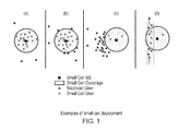
- Figure 5 illustrates a simple example where applying a directional pattern resulted in capturing a user while additional inference is created for larger number of users. Such scenarios are indeed quite possible due to the shape of most hotspots.
- Uplink Sniffing This is probably the simplest but least accurate way for a base-station to estimates its interference impact on other users.
- the base-station measures the total detected energy on the uplink frequencies. Since most of the time a cell is idle, the detected power would correspond to users of other cells communicating with their own serving cell. Since the base-station uses this measure merely to compare different antenna patterns, higher detected power implies higher directivity towards other-cells' users' hence higher likelihood of creating interference to those users.
- the absolute values of the uplink power cannot be directly interpreted by the base-station since the power used for an uplink signal by user equipment may be dependent on the distance of the users to their serving cell as well as the uplink load level of the serving cell.
- recent studies suggest that data traffic is becoming more and more asymmetrical implying much less uplink activities compared to the downlink.
- the base-station virtually increases its cell size using the range extension bias and observes the corresponding increase in the number of inbound handover requests. Since the cell extension bias may have been set to an unreasonably large value, the base-station might reject some of those handover requests but can use this information to estimate how many users are in the close vicinity of the cell border.
- Information exchange with underlying macrocell/ neighbouring small cells this is the most accurate way for a base-station to estimate its interference impact on users of other cell.
- users measure the received pilot power from neighbouring cells. This is a critical procedure especially for triggering handover events.
- the underlying macro-base-station can simply exchange this information with the small cells. More specifically, the macrocell can define a power threshold and identify the number of users and the ratio of time where the received power from a small cell base-station exceeds this threshold. The macrocell can then send this processed information together with the appropriate time stamps to the small cell base-station. Using the time stamps, the small cell base-station would then be able to derive which antenna pattern created the highest interference to the macrocell users.
- a fitness function comprising performance indicators associated with the above three criterion can be defined.
- the actual metric used to reflect the performance associated with each criterion could vary.
- the offloading gain can be described as the ratio of active time of the cell or as the total traffic volume transferred using each of the available antenna patterns.
- the fitness function may apply different weights to different criterion so as to take into account the operator's priorities.
- the optimal pattern is simply be the one that can maximise the resulting fitness function.
- the base-station can divide the time into long-enough intra-day regimes (say each about 4-5 hours) and calculate the optimal antenna pattern for each regime separately. This can be especially useful since the distribution of users may change over the time (e.g. during business or evening hours), hence different antenna patterns might be suitable for different time intervals during the day.
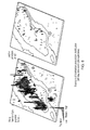
- Figure 6 shows an example of users' distribution in Manhattan, NYin day and night time.
- FIG. 7(a) shows an example of fitness values associated to four antenna patterns.
- the averaged fitness is shown in figure 7(b) .
- the base station should select antenna pattern 1 until 18h and then switch to antenna pattern 3 for the rest of the day. Once such optimal antenna patterns are derived based on long enough observation periods, the base-station would stick with them.
- FIG 8 shows a small cell base station 20 according to an embodiment of the present invention.
- the small cell base station 10 comprises a four element antenna 30 similar to those shown in figure 2 with switching circuitry 32 for selectively feeding the different antenna elements with signals to and from the receiver/ transmitter circuitry 40.
- control circuitry 50 which controls the switching circuitry and comprises measurement circuitry 52 for measuring performance indicators such as traffic offload values, interference impact and user mobility during an exploration stage during which the control circuitry 52 controls the switching circuitry 32 to periodically switch between antenna elements in a way similar to that shown in figure 4 and selection circuitry 54 which derives a preferred antenna pattern from the measurements taken during the exploration stage, the control circuitry 50 controlling the switching circuitry to use the preferred antenna pattern during an exploitation stage in which the base station 20 serves users.
- Figure 9 shows a flow diagram illustrating steps in a method according to an embodiment of the present invention. Initially during the exploration phase a first possible antenna pattern is selected and indications of performance are measured during a predetermined time period. When the time period has expired it is determined whether there are any users currently connected and if so this antenna pattern remains selected until this is no longer the case. It is then determined if all of the possible antenna patterns have been selected and if so if the total number of measurements taken exceed a predetermined number. If not all the antenna patterns have been selected or if not enough measurements have been taken then the next antenna pattern is selected.
- the measured indications of performance for each antenna pattern are combined to generate a performance function, the fitness function of Figure 7 and from this the antenna with the best performance is selected and the small cell base stations operates configured to generate this antenna pattern.
- the exploration phase is repeated periodically to ensure that traffic has not changed over time and that the best antenna pattern is being used. Alternatively during operation indication of performance may be taken and if performance drops then either a different antenna pattern maybe selected, or the exploration phase may be repeated.
- the exploration phase was continued until the number of measurements exceeded a predetermined number. As noted above it could also be performed for a predetermined time. Each of these factors being determined to provide a statistically significant sample. In effect determining when to stop collecting measurements and to make a decision with regard to which antenna pattern(s) to select and retain is an important and practical consideration. In some embodiments in order to do this, the algorithm should ensure that the offloading gain of the base-station is estimated with high enough accuracy. This is akin to determining the expected number of users being served when each of the antenna patterns are selected. The calls/ data session arrivals can be modelled as a Poisson process. The base-station then needs to accurately estimate the calls/ data session arrival rate, A, in a time-unit for each antenna pattern.
- a and ⁇ M .
- P u For a Poisson process, the mean and the variance are both A.
- the standard error can be calculated as ⁇ n where n is the number of calls/data sessions observed.
- the base-station may be able to select a combined antenna pattern without explicitly trying that pattern.
- a combined pattern may have smaller directional gain.
- the base-station would be able to estimate the fitness or performance function if a combined pattern is selected. This can be realised using the following steps:
- Another advantage of using multi-element antenna system is the fact that the small cell coverage can be extended significantly in some particular directions. This is especially the case when considering co-channel deployments of small cells. In fact the coverage area of small cells would significantly depend on the received pilot power from the underlying macrocell. This is evidently the case since the small cell coverage is defined where the pilot is above that of macrocell (although there might be some range expansion biases applied).
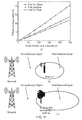
- Figure 11a shows the effective coverage radius of the small cell as a function of distance to the underlying macrocell.
- the coverage area of the small cell is normally asymmetrical (see Figure 11b ).
- Applying the antenna gain pattern to the direction where macrocell signal is weaker can result in significant expansion of the cell coverage area ( Figure 11c ).
- offloading macrocell edge users is more critical as they are normally suffering from poor service quality as a result of lower signal SINR.
- multi-element patch antennas are described above such an antenna could be replaced with an antenna array with a switched feeder network that can create fixed beams in a similar way. In effect it is the ability of the antenna to generate antenna patterns that can change the geographical area of the radio coverage that is important.
- program storage devices e.g., digital data storage media, which are machine or computer readable and encode machine-executable or computer-executable programs of instructions, wherein said instructions perform some or all of the steps of said above-described methods.
- the program storage devices may be, e.g., digital memories, magnetic storage media such as a magnetic disks and magnetic tapes, hard drives, or optically readable digital data storage media.
- the embodiments are also intended to cover computers programmed to perform said steps of the above-described methods.
- processors may be provided through the use of dedicated hardware as well as hardware capable of executing software in association with appropriate software.
- the functions may be provided by a single dedicated processor, by a single shared processor, or by a plurality of individual processors, some of which may be shared.
- processor or “controller” or “logic” should not be construed to refer exclusively to hardware capable of executing software, and may implicitly include, without limitation, digital signal processor (DSP) hardware, network processor, application specific integrated circuit (ASIC), field programmable gate array (FPGA), read only memory (ROM) for storing software, random access memory (RAM), and non-volatile storage. Other hardware, conventional and/or custom, may also be included.
- DSP digital signal processor
- ASIC application specific integrated circuit
- FPGA field programmable gate array
- ROM read only memory
- RAM random access memory
- non-volatile storage Other hardware, conventional and/or custom, may also be included.
- any switches shown in the Figures are conceptual only. Their function may be carried out through the operation of program logic, through dedicated logic, through the interaction of program control and dedicated logic, or even manually, the particular technique being selectable by the implementer as more specifically understood from the context.
- any block diagrams herein represent conceptual views of illustrative circuitry embodying the principles of the invention.
- any flow charts, flow diagrams, state transition diagrams, pseudo code, and the like represent various processes which may be substantially represented in computer readable medium and so executed by a computer or processor, whether or not such computer or processor is explicitly shown.
Landscapes
- Engineering & Computer Science (AREA)
- Computer Networks & Wireless Communication (AREA)
- Signal Processing (AREA)
- Mobile Radio Communication Systems (AREA)
Priority Applications (1)
| Application Number | Priority Date | Filing Date | Title |
|---|---|---|---|
| EP14305677.8A EP2943003B1 (de) | 2014-05-09 | 2014-05-09 | Kleinzelliger Basisstationseinsatz in zellularen Netzwerken |
Applications Claiming Priority (1)
| Application Number | Priority Date | Filing Date | Title |
|---|---|---|---|
| EP14305677.8A EP2943003B1 (de) | 2014-05-09 | 2014-05-09 | Kleinzelliger Basisstationseinsatz in zellularen Netzwerken |
Publications (2)
| Publication Number | Publication Date |
|---|---|
| EP2943003A1 true EP2943003A1 (de) | 2015-11-11 |
| EP2943003B1 EP2943003B1 (de) | 2020-08-12 |
Family
ID=50774805
Family Applications (1)
| Application Number | Title | Priority Date | Filing Date |
|---|---|---|---|
| EP14305677.8A Not-in-force EP2943003B1 (de) | 2014-05-09 | 2014-05-09 | Kleinzelliger Basisstationseinsatz in zellularen Netzwerken |
Country Status (1)
| Country | Link |
|---|---|
| EP (1) | EP2943003B1 (de) |
Cited By (2)
| Publication number | Priority date | Publication date | Assignee | Title |
|---|---|---|---|---|
| CN114339857A (zh) * | 2021-12-07 | 2022-04-12 | 重庆邮电大学 | 超密集异构无线网络中基于网络相似性的垂直切换方法 |
| CN118158764A (zh) * | 2024-02-27 | 2024-06-07 | 中国人民警察大学(公安部国际执法合作学院、中国维和警察培训中心) | 一种vlc-rf异构网络的随机几何切换建模方法 |
Citations (6)
| Publication number | Priority date | Publication date | Assignee | Title |
|---|---|---|---|---|
| GB2361385A (en) * | 2000-04-12 | 2001-10-17 | Queen Mary & Westfield College | Intelligent control of radio resorces in a wireless network |
| WO2002015326A2 (en) * | 2000-08-15 | 2002-02-21 | Celletra Ltd. | Optimizing clever antenna by beam tilting |
| EP1748664A2 (de) * | 2005-07-25 | 2007-01-31 | NTT DoCoMo INC. | Drahtlose Steuerungsvorrichtung und Kommunikationsverfahren |
| US20100296401A1 (en) * | 2009-05-22 | 2010-11-25 | Jeyhan Karaoguz | Multi-dimensional resource management in a wireless network |
| US20110009105A1 (en) * | 2009-07-13 | 2011-01-13 | Jungwoo Lee | Self-organizing networks using directional beam antennas |
| US20110136478A1 (en) * | 2009-12-09 | 2011-06-09 | Hafedh Trigui | Self-optimizing networks for fixed wireless access |
-
2014
- 2014-05-09 EP EP14305677.8A patent/EP2943003B1/de not_active Not-in-force
Patent Citations (6)
| Publication number | Priority date | Publication date | Assignee | Title |
|---|---|---|---|---|
| GB2361385A (en) * | 2000-04-12 | 2001-10-17 | Queen Mary & Westfield College | Intelligent control of radio resorces in a wireless network |
| WO2002015326A2 (en) * | 2000-08-15 | 2002-02-21 | Celletra Ltd. | Optimizing clever antenna by beam tilting |
| EP1748664A2 (de) * | 2005-07-25 | 2007-01-31 | NTT DoCoMo INC. | Drahtlose Steuerungsvorrichtung und Kommunikationsverfahren |
| US20100296401A1 (en) * | 2009-05-22 | 2010-11-25 | Jeyhan Karaoguz | Multi-dimensional resource management in a wireless network |
| US20110009105A1 (en) * | 2009-07-13 | 2011-01-13 | Jungwoo Lee | Self-organizing networks using directional beam antennas |
| US20110136478A1 (en) * | 2009-12-09 | 2011-06-09 | Hafedh Trigui | Self-optimizing networks for fixed wireless access |
Cited By (3)
| Publication number | Priority date | Publication date | Assignee | Title |
|---|---|---|---|---|
| CN114339857A (zh) * | 2021-12-07 | 2022-04-12 | 重庆邮电大学 | 超密集异构无线网络中基于网络相似性的垂直切换方法 |
| CN114339857B (zh) * | 2021-12-07 | 2023-07-25 | 重庆邮电大学 | 超密集异构无线网络中基于网络相似性的垂直切换方法 |
| CN118158764A (zh) * | 2024-02-27 | 2024-06-07 | 中国人民警察大学(公安部国际执法合作学院、中国维和警察培训中心) | 一种vlc-rf异构网络的随机几何切换建模方法 |
Also Published As
| Publication number | Publication date |
|---|---|
| EP2943003B1 (de) | 2020-08-12 |
Similar Documents
| Publication | Publication Date | Title |
|---|---|---|
| US12633997B2 (en) | Communications device and method | |
| US12185145B2 (en) | Methods and network nodes for configuring almost blank subframe transmission patterns and corresponding measurement patterns for reducing intercell interference in an heterogeneous cellular radio communication system | |
| US10305561B2 (en) | Communication method and apparatus using beamforming | |
| EP2850880B1 (de) | Kooperation zwischen zellen zur durchführung von übergabeentscheidungen bei multisektoreinsätzen | |
| EP2506625B1 (de) | Kleinzellige basisstation mit mehrfachen antennen und verfahren zur steuerung der empfangsmuster durch auswahl eines untersatzes der zu verwendenden antennen | |
| EP3520254B1 (de) | Verfahren und anordnungen zur funkstreckenmesskonfiguration | |
| US8606312B2 (en) | Method for controlling transmission power in cellular system | |
| US9037142B2 (en) | Cell planning method for wireless communication systems | |
| US9615265B2 (en) | Network node and method for adjusting antenna parameters in a wireless communications system | |
| CN103491553B (zh) | 一种波束调整方法和设备 | |
| US8880088B2 (en) | Signalling for interference management in HETNETs | |
| EP3228119B1 (de) | Messberichtsauslösung zur koordination zwischen zellen in zellularem einsatz | |
| EP3205032B1 (de) | Zellenformung in drahtloskommunikationsnetzen | |
| JPWO2016143238A1 (ja) | カバレッジ制御方法、基地局装置、無線通信システムおよび基地局制御プログラムを格納した非一時的なコンピュータ可読媒体 | |
| EP2880889B1 (de) | Verfahren und vorrichtung zur nutzung in einem mobilkommunikationsnetz | |
| US9693358B2 (en) | Communication control method, mobile communication system, and base station | |
| GB2559424A (en) | Communication system | |
| US20160254886A1 (en) | Inter-cell coordination in cellular deployment | |
| López-Pérez et al. | Duty cycles and load balancing in HetNets with eICIC almost blank subframes | |
| US10111183B2 (en) | Method of controlling power and wireless communication system | |
| JP5444298B2 (ja) | 無線通信システム、無線基地局および通信制御方法 | |
| EP2943003B1 (de) | Kleinzelliger Basisstationseinsatz in zellularen Netzwerken | |
| EP2835923B1 (de) | Benutzergerät und Verfahren zur CQI Rückmeldung mit Interferenz unterdrückungsfähigem Empfänger | |
| JP5159863B2 (ja) | 無線基地局装置、無線部制御装置及び無線通信方法 | |
| Castro-Hernandez et al. | A distributed load balancing algorithm for LTE/LTE-A heterogeneous networks |
Legal Events
| Date | Code | Title | Description |
|---|---|---|---|
| PUAI | Public reference made under article 153(3) epc to a published international application that has entered the european phase |
Free format text: ORIGINAL CODE: 0009012 |
|
| AK | Designated contracting states |
Kind code of ref document: A1 Designated state(s): AL AT BE BG CH CY CZ DE DK EE ES FI FR GB GR HR HU IE IS IT LI LT LU LV MC MK MT NL NO PL PT RO RS SE SI SK SM TR |
|
| AX | Request for extension of the european patent |
Extension state: BA ME |
|
| 17P | Request for examination filed |
Effective date: 20160511 |
|
| RBV | Designated contracting states (corrected) |
Designated state(s): AL AT BE BG CH CY CZ DE DK EE ES FI FR GB GR HR HU IE IS IT LI LT LU LV MC MK MT NL NO PL PT RO RS SE SI SK SM TR |
|
| RAP1 | Party data changed (applicant data changed or rights of an application transferred) |
Owner name: ALCATEL LUCENT |
|
| STAA | Information on the status of an ep patent application or granted ep patent |
Free format text: STATUS: EXAMINATION IS IN PROGRESS |
|
| 17Q | First examination report despatched |
Effective date: 20190104 |
|
| GRAP | Despatch of communication of intention to grant a patent |
Free format text: ORIGINAL CODE: EPIDOSNIGR1 |
|
| STAA | Information on the status of an ep patent application or granted ep patent |
Free format text: STATUS: GRANT OF PATENT IS INTENDED |
|
| INTG | Intention to grant announced |
Effective date: 20200113 |
|
| GRAJ | Information related to disapproval of communication of intention to grant by the applicant or resumption of examination proceedings by the epo deleted |
Free format text: ORIGINAL CODE: EPIDOSDIGR1 |
|
| STAA | Information on the status of an ep patent application or granted ep patent |
Free format text: STATUS: EXAMINATION IS IN PROGRESS |
|
| GRAP | Despatch of communication of intention to grant a patent |
Free format text: ORIGINAL CODE: EPIDOSNIGR1 |
|
| STAA | Information on the status of an ep patent application or granted ep patent |
Free format text: STATUS: GRANT OF PATENT IS INTENDED |
|
| INTC | Intention to grant announced (deleted) | ||
| INTG | Intention to grant announced |
Effective date: 20200428 |
|
| GRAS | Grant fee paid |
Free format text: ORIGINAL CODE: EPIDOSNIGR3 |
|
| GRAA | (expected) grant |
Free format text: ORIGINAL CODE: 0009210 |
|
| STAA | Information on the status of an ep patent application or granted ep patent |
Free format text: STATUS: THE PATENT HAS BEEN GRANTED |
|
| AK | Designated contracting states |
Kind code of ref document: B1 Designated state(s): AL AT BE BG CH CY CZ DE DK EE ES FI FR GB GR HR HU IE IS IT LI LT LU LV MC MK MT NL NO PL PT RO RS SE SI SK SM TR |
|
| REG | Reference to a national code |
Ref country code: CH Ref legal event code: EP |
|
| REG | Reference to a national code |
Ref country code: IE Ref legal event code: FG4D |
|
| REG | Reference to a national code |
Ref country code: DE Ref legal event code: R096 Ref document number: 602014068832 Country of ref document: DE |
|
| REG | Reference to a national code |
Ref country code: AT Ref legal event code: REF Ref document number: 1302793 Country of ref document: AT Kind code of ref document: T Effective date: 20200915 |
|
| REG | Reference to a national code |
Ref country code: LT Ref legal event code: MG4D |
|
| REG | Reference to a national code |
Ref country code: NL Ref legal event code: MP Effective date: 20200812 |
|
| PG25 | Lapsed in a contracting state [announced via postgrant information from national office to epo] |
Ref country code: LT Free format text: LAPSE BECAUSE OF FAILURE TO SUBMIT A TRANSLATION OF THE DESCRIPTION OR TO PAY THE FEE WITHIN THE PRESCRIBED TIME-LIMIT Effective date: 20200812 Ref country code: HR Free format text: LAPSE BECAUSE OF FAILURE TO SUBMIT A TRANSLATION OF THE DESCRIPTION OR TO PAY THE FEE WITHIN THE PRESCRIBED TIME-LIMIT Effective date: 20200812 Ref country code: SE Free format text: LAPSE BECAUSE OF FAILURE TO SUBMIT A TRANSLATION OF THE DESCRIPTION OR TO PAY THE FEE WITHIN THE PRESCRIBED TIME-LIMIT Effective date: 20200812 Ref country code: GR Free format text: LAPSE BECAUSE OF FAILURE TO SUBMIT A TRANSLATION OF THE DESCRIPTION OR TO PAY THE FEE WITHIN THE PRESCRIBED TIME-LIMIT Effective date: 20201113 Ref country code: FI Free format text: LAPSE BECAUSE OF FAILURE TO SUBMIT A TRANSLATION OF THE DESCRIPTION OR TO PAY THE FEE WITHIN THE PRESCRIBED TIME-LIMIT Effective date: 20200812 Ref country code: NO Free format text: LAPSE BECAUSE OF FAILURE TO SUBMIT A TRANSLATION OF THE DESCRIPTION OR TO PAY THE FEE WITHIN THE PRESCRIBED TIME-LIMIT Effective date: 20201112 Ref country code: BG Free format text: LAPSE BECAUSE OF FAILURE TO SUBMIT A TRANSLATION OF THE DESCRIPTION OR TO PAY THE FEE WITHIN THE PRESCRIBED TIME-LIMIT Effective date: 20201112 Ref country code: ES Free format text: LAPSE BECAUSE OF FAILURE TO SUBMIT A TRANSLATION OF THE DESCRIPTION OR TO PAY THE FEE WITHIN THE PRESCRIBED TIME-LIMIT Effective date: 20200812 |
|
| REG | Reference to a national code |
Ref country code: AT Ref legal event code: MK05 Ref document number: 1302793 Country of ref document: AT Kind code of ref document: T Effective date: 20200812 |
|
| PG25 | Lapsed in a contracting state [announced via postgrant information from national office to epo] |
Ref country code: PL Free format text: LAPSE BECAUSE OF FAILURE TO SUBMIT A TRANSLATION OF THE DESCRIPTION OR TO PAY THE FEE WITHIN THE PRESCRIBED TIME-LIMIT Effective date: 20200812 Ref country code: RS Free format text: LAPSE BECAUSE OF FAILURE TO SUBMIT A TRANSLATION OF THE DESCRIPTION OR TO PAY THE FEE WITHIN THE PRESCRIBED TIME-LIMIT Effective date: 20200812 Ref country code: NL Free format text: LAPSE BECAUSE OF FAILURE TO SUBMIT A TRANSLATION OF THE DESCRIPTION OR TO PAY THE FEE WITHIN THE PRESCRIBED TIME-LIMIT Effective date: 20200812 Ref country code: LV Free format text: LAPSE BECAUSE OF FAILURE TO SUBMIT A TRANSLATION OF THE DESCRIPTION OR TO PAY THE FEE WITHIN THE PRESCRIBED TIME-LIMIT Effective date: 20200812 Ref country code: IS Free format text: LAPSE BECAUSE OF FAILURE TO SUBMIT A TRANSLATION OF THE DESCRIPTION OR TO PAY THE FEE WITHIN THE PRESCRIBED TIME-LIMIT Effective date: 20201212 |
|
| PG25 | Lapsed in a contracting state [announced via postgrant information from national office to epo] |
Ref country code: EE Free format text: LAPSE BECAUSE OF FAILURE TO SUBMIT A TRANSLATION OF THE DESCRIPTION OR TO PAY THE FEE WITHIN THE PRESCRIBED TIME-LIMIT Effective date: 20200812 Ref country code: CZ Free format text: LAPSE BECAUSE OF FAILURE TO SUBMIT A TRANSLATION OF THE DESCRIPTION OR TO PAY THE FEE WITHIN THE PRESCRIBED TIME-LIMIT Effective date: 20200812 Ref country code: DK Free format text: LAPSE BECAUSE OF FAILURE TO SUBMIT A TRANSLATION OF THE DESCRIPTION OR TO PAY THE FEE WITHIN THE PRESCRIBED TIME-LIMIT Effective date: 20200812 Ref country code: SM Free format text: LAPSE BECAUSE OF FAILURE TO SUBMIT A TRANSLATION OF THE DESCRIPTION OR TO PAY THE FEE WITHIN THE PRESCRIBED TIME-LIMIT Effective date: 20200812 Ref country code: RO Free format text: LAPSE BECAUSE OF FAILURE TO SUBMIT A TRANSLATION OF THE DESCRIPTION OR TO PAY THE FEE WITHIN THE PRESCRIBED TIME-LIMIT Effective date: 20200812 |
|
| REG | Reference to a national code |
Ref country code: DE Ref legal event code: R097 Ref document number: 602014068832 Country of ref document: DE |
|
| PG25 | Lapsed in a contracting state [announced via postgrant information from national office to epo] |
Ref country code: AL Free format text: LAPSE BECAUSE OF FAILURE TO SUBMIT A TRANSLATION OF THE DESCRIPTION OR TO PAY THE FEE WITHIN THE PRESCRIBED TIME-LIMIT Effective date: 20200812 Ref country code: AT Free format text: LAPSE BECAUSE OF FAILURE TO SUBMIT A TRANSLATION OF THE DESCRIPTION OR TO PAY THE FEE WITHIN THE PRESCRIBED TIME-LIMIT Effective date: 20200812 |
|
| PLBE | No opposition filed within time limit |
Free format text: ORIGINAL CODE: 0009261 |
|
| STAA | Information on the status of an ep patent application or granted ep patent |
Free format text: STATUS: NO OPPOSITION FILED WITHIN TIME LIMIT |
|
| PG25 | Lapsed in a contracting state [announced via postgrant information from national office to epo] |
Ref country code: SK Free format text: LAPSE BECAUSE OF FAILURE TO SUBMIT A TRANSLATION OF THE DESCRIPTION OR TO PAY THE FEE WITHIN THE PRESCRIBED TIME-LIMIT Effective date: 20200812 |
|
| 26N | No opposition filed |
Effective date: 20210514 |
|
| PG25 | Lapsed in a contracting state [announced via postgrant information from national office to epo] |
Ref country code: IT Free format text: LAPSE BECAUSE OF FAILURE TO SUBMIT A TRANSLATION OF THE DESCRIPTION OR TO PAY THE FEE WITHIN THE PRESCRIBED TIME-LIMIT Effective date: 20200812 |
|
| PG25 | Lapsed in a contracting state [announced via postgrant information from national office to epo] |
Ref country code: SI Free format text: LAPSE BECAUSE OF FAILURE TO SUBMIT A TRANSLATION OF THE DESCRIPTION OR TO PAY THE FEE WITHIN THE PRESCRIBED TIME-LIMIT Effective date: 20200812 |
|
| REG | Reference to a national code |
Ref country code: CH Ref legal event code: PL |
|
| PG25 | Lapsed in a contracting state [announced via postgrant information from national office to epo] |
Ref country code: MC Free format text: LAPSE BECAUSE OF FAILURE TO SUBMIT A TRANSLATION OF THE DESCRIPTION OR TO PAY THE FEE WITHIN THE PRESCRIBED TIME-LIMIT Effective date: 20200812 Ref country code: LI Free format text: LAPSE BECAUSE OF NON-PAYMENT OF DUE FEES Effective date: 20210531 Ref country code: LU Free format text: LAPSE BECAUSE OF NON-PAYMENT OF DUE FEES Effective date: 20210509 Ref country code: CH Free format text: LAPSE BECAUSE OF NON-PAYMENT OF DUE FEES Effective date: 20210531 |
|
| REG | Reference to a national code |
Ref country code: BE Ref legal event code: MM Effective date: 20210531 |
|
| PG25 | Lapsed in a contracting state [announced via postgrant information from national office to epo] |
Ref country code: IE Free format text: LAPSE BECAUSE OF NON-PAYMENT OF DUE FEES Effective date: 20210509 |
|
| PG25 | Lapsed in a contracting state [announced via postgrant information from national office to epo] |
Ref country code: FR Free format text: LAPSE BECAUSE OF NON-PAYMENT OF DUE FEES Effective date: 20210531 |
|
| PG25 | Lapsed in a contracting state [announced via postgrant information from national office to epo] |
Ref country code: BE Free format text: LAPSE BECAUSE OF NON-PAYMENT OF DUE FEES Effective date: 20210531 |
|
| PGFP | Annual fee paid to national office [announced via postgrant information from national office to epo] |
Ref country code: GB Payment date: 20220401 Year of fee payment: 9 Ref country code: DE Payment date: 20220329 Year of fee payment: 9 |
|
| PG25 | Lapsed in a contracting state [announced via postgrant information from national office to epo] |
Ref country code: PT Free format text: LAPSE BECAUSE OF FAILURE TO SUBMIT A TRANSLATION OF THE DESCRIPTION OR TO PAY THE FEE WITHIN THE PRESCRIBED TIME-LIMIT Effective date: 20201214 |
|
| PG25 | Lapsed in a contracting state [announced via postgrant information from national office to epo] |
Ref country code: HU Free format text: LAPSE BECAUSE OF FAILURE TO SUBMIT A TRANSLATION OF THE DESCRIPTION OR TO PAY THE FEE WITHIN THE PRESCRIBED TIME-LIMIT; INVALID AB INITIO Effective date: 20140509 |
|
| PG25 | Lapsed in a contracting state [announced via postgrant information from national office to epo] |
Ref country code: CY Free format text: LAPSE BECAUSE OF FAILURE TO SUBMIT A TRANSLATION OF THE DESCRIPTION OR TO PAY THE FEE WITHIN THE PRESCRIBED TIME-LIMIT Effective date: 20200812 |
|
| REG | Reference to a national code |
Ref country code: DE Ref legal event code: R119 Ref document number: 602014068832 Country of ref document: DE |
|
| GBPC | Gb: european patent ceased through non-payment of renewal fee |
Effective date: 20230509 |
|
| PG25 | Lapsed in a contracting state [announced via postgrant information from national office to epo] |
Ref country code: MK Free format text: LAPSE BECAUSE OF FAILURE TO SUBMIT A TRANSLATION OF THE DESCRIPTION OR TO PAY THE FEE WITHIN THE PRESCRIBED TIME-LIMIT Effective date: 20200812 Ref country code: DE Free format text: LAPSE BECAUSE OF NON-PAYMENT OF DUE FEES Effective date: 20231201 Ref country code: GB Free format text: LAPSE BECAUSE OF NON-PAYMENT OF DUE FEES Effective date: 20230509 |
|
| PG25 | Lapsed in a contracting state [announced via postgrant information from national office to epo] |
Ref country code: MT Free format text: LAPSE BECAUSE OF FAILURE TO SUBMIT A TRANSLATION OF THE DESCRIPTION OR TO PAY THE FEE WITHIN THE PRESCRIBED TIME-LIMIT Effective date: 20200812 |
|
| PG25 | Lapsed in a contracting state [announced via postgrant information from national office to epo] |
Ref country code: TR Free format text: LAPSE BECAUSE OF FAILURE TO SUBMIT A TRANSLATION OF THE DESCRIPTION OR TO PAY THE FEE WITHIN THE PRESCRIBED TIME-LIMIT Effective date: 20200812 |