EP2943111B1 - Laparoskopische ultraschallsonde für elastografische bildgebung mit automatisiertem oszillationsmechanismus - Google Patents
Laparoskopische ultraschallsonde für elastografische bildgebung mit automatisiertem oszillationsmechanismus Download PDFInfo
- Publication number
- EP2943111B1 EP2943111B1 EP13704631.4A EP13704631A EP2943111B1 EP 2943111 B1 EP2943111 B1 EP 2943111B1 EP 13704631 A EP13704631 A EP 13704631A EP 2943111 B1 EP2943111 B1 EP 2943111B1
- Authority
- EP
- European Patent Office
- Prior art keywords
- probe
- cable
- probe head
- guide
- ultrasound
- Prior art date
- Legal status (The legal status is an assumption and is not a legal conclusion. Google has not performed a legal analysis and makes no representation as to the accuracy of the status listed.)
- Not-in-force
Links
- 239000000523 sample Substances 0.000 title claims description 122
- 238000002604 ultrasonography Methods 0.000 title claims description 38
- 238000003384 imaging method Methods 0.000 title claims description 26
- 230000007246 mechanism Effects 0.000 title description 3
- 230000010355 oscillation Effects 0.000 title description 3
- 238000000034 method Methods 0.000 claims description 14
- 239000012530 fluid Substances 0.000 claims description 12
- 238000012285 ultrasound imaging Methods 0.000 claims description 8
- 230000004044 response Effects 0.000 claims description 4
- 230000000881 depressing effect Effects 0.000 claims 1
- 238000002592 echocardiography Methods 0.000 description 12
- 238000002091 elastography Methods 0.000 description 6
- 230000006835 compression Effects 0.000 description 5
- 238000007906 compression Methods 0.000 description 5
- 238000004891 communication Methods 0.000 description 3
- 230000008569 process Effects 0.000 description 3
- 238000012545 processing Methods 0.000 description 3
- 206010028980 Neoplasm Diseases 0.000 description 2
- 230000004075 alteration Effects 0.000 description 2
- 238000013459 approach Methods 0.000 description 2
- 238000001574 biopsy Methods 0.000 description 2
- 230000001934 delay Effects 0.000 description 2
- 238000006073 displacement reaction Methods 0.000 description 2
- 238000001914 filtration Methods 0.000 description 2
- 230000006870 function Effects 0.000 description 2
- 239000007788 liquid Substances 0.000 description 2
- 238000012986 modification Methods 0.000 description 2
- 230000004048 modification Effects 0.000 description 2
- 230000001052 transient effect Effects 0.000 description 2
- 210000001015 abdomen Anatomy 0.000 description 1
- 230000003213 activating effect Effects 0.000 description 1
- 230000004913 activation Effects 0.000 description 1
- 239000012190 activator Substances 0.000 description 1
- 238000003491 array Methods 0.000 description 1
- 230000002238 attenuated effect Effects 0.000 description 1
- 230000001427 coherent effect Effects 0.000 description 1
- 230000000295 complement effect Effects 0.000 description 1
- 238000013461 design Methods 0.000 description 1
- 230000000694 effects Effects 0.000 description 1
- 239000000284 extract Substances 0.000 description 1
- 210000000232 gallbladder Anatomy 0.000 description 1
- 238000002347 injection Methods 0.000 description 1
- 239000007924 injection Substances 0.000 description 1
- 230000003993 interaction Effects 0.000 description 1
- 238000013152 interventional procedure Methods 0.000 description 1
- 230000001788 irregular Effects 0.000 description 1
- 210000004185 liver Anatomy 0.000 description 1
- 239000011159 matrix material Substances 0.000 description 1
- 230000000116 mitigating effect Effects 0.000 description 1
- 230000037361 pathway Effects 0.000 description 1
- 238000007674 radiofrequency ablation Methods 0.000 description 1
- 230000000306 recurrent effect Effects 0.000 description 1
- 238000009877 rendering Methods 0.000 description 1
- 230000003068 static effect Effects 0.000 description 1
- 239000000126 substance Substances 0.000 description 1
- 230000007704 transition Effects 0.000 description 1
- 230000000007 visual effect Effects 0.000 description 1
Images


Classifications
-
- A—HUMAN NECESSITIES
- A61—MEDICAL OR VETERINARY SCIENCE; HYGIENE
- A61B—DIAGNOSIS; SURGERY; IDENTIFICATION
- A61B8/00—Diagnosis using ultrasonic, sonic or infrasonic waves
- A61B8/44—Constructional features of the ultrasonic, sonic or infrasonic diagnostic device
- A61B8/4444—Constructional features of the ultrasonic, sonic or infrasonic diagnostic device related to the probe
- A61B8/4461—Features of the scanning mechanism, e.g. for moving the transducer within the housing of the probe
-
- A—HUMAN NECESSITIES
- A61—MEDICAL OR VETERINARY SCIENCE; HYGIENE
- A61B—DIAGNOSIS; SURGERY; IDENTIFICATION
- A61B1/00—Instruments for performing medical examinations of the interior of cavities or tubes of the body by visual or photographical inspection, e.g. endoscopes; Illuminating arrangements therefor
- A61B1/005—Flexible endoscopes
- A61B1/0051—Flexible endoscopes with controlled bending of insertion part
- A61B1/0052—Constructional details of control elements, e.g. handles
-
- A—HUMAN NECESSITIES
- A61—MEDICAL OR VETERINARY SCIENCE; HYGIENE
- A61B—DIAGNOSIS; SURGERY; IDENTIFICATION
- A61B1/00—Instruments for performing medical examinations of the interior of cavities or tubes of the body by visual or photographical inspection, e.g. endoscopes; Illuminating arrangements therefor
- A61B1/005—Flexible endoscopes
- A61B1/0051—Flexible endoscopes with controlled bending of insertion part
- A61B1/0057—Constructional details of force transmission elements, e.g. control wires
-
- A—HUMAN NECESSITIES
- A61—MEDICAL OR VETERINARY SCIENCE; HYGIENE
- A61B—DIAGNOSIS; SURGERY; IDENTIFICATION
- A61B8/00—Diagnosis using ultrasonic, sonic or infrasonic waves
- A61B8/12—Diagnosis using ultrasonic, sonic or infrasonic waves in body cavities or body tracts, e.g. by using catheters
-
- A—HUMAN NECESSITIES
- A61—MEDICAL OR VETERINARY SCIENCE; HYGIENE
- A61B—DIAGNOSIS; SURGERY; IDENTIFICATION
- A61B8/00—Diagnosis using ultrasonic, sonic or infrasonic waves
- A61B8/44—Constructional features of the ultrasonic, sonic or infrasonic diagnostic device
- A61B8/4444—Constructional features of the ultrasonic, sonic or infrasonic diagnostic device related to the probe
- A61B8/4455—Features of the external shape of the probe, e.g. ergonomic aspects
-
- A—HUMAN NECESSITIES
- A61—MEDICAL OR VETERINARY SCIENCE; HYGIENE
- A61B—DIAGNOSIS; SURGERY; IDENTIFICATION
- A61B8/00—Diagnosis using ultrasonic, sonic or infrasonic waves
- A61B8/44—Constructional features of the ultrasonic, sonic or infrasonic diagnostic device
- A61B8/4444—Constructional features of the ultrasonic, sonic or infrasonic diagnostic device related to the probe
- A61B8/4461—Features of the scanning mechanism, e.g. for moving the transducer within the housing of the probe
- A61B8/4466—Features of the scanning mechanism, e.g. for moving the transducer within the housing of the probe involving deflection of the probe
-
- A—HUMAN NECESSITIES
- A61—MEDICAL OR VETERINARY SCIENCE; HYGIENE
- A61B—DIAGNOSIS; SURGERY; IDENTIFICATION
- A61B8/00—Diagnosis using ultrasonic, sonic or infrasonic waves
- A61B8/44—Constructional features of the ultrasonic, sonic or infrasonic diagnostic device
- A61B8/4483—Constructional features of the ultrasonic, sonic or infrasonic diagnostic device characterised by features of the ultrasound transducer
-
- A—HUMAN NECESSITIES
- A61—MEDICAL OR VETERINARY SCIENCE; HYGIENE
- A61B—DIAGNOSIS; SURGERY; IDENTIFICATION
- A61B8/00—Diagnosis using ultrasonic, sonic or infrasonic waves
- A61B8/48—Diagnostic techniques
- A61B8/485—Diagnostic techniques involving measuring strain or elastic properties
Definitions
- the following generally relates to ultrasound and more particularly to an ultrasound probe and is described with particular application to ultrasound imaging; however, the probe can be employed with other ultrasound applications.
- Ultrasound (US) imaging has provided useful information about the interior characteristics of an object or subject under examination.
- a US imaging system has included an ultrasound probe housing a transducer array that is configured to transmit an ultrasound signal into a scan field of view and receive echoes produced in response to the ultrasound signal interacting with structure of an object or subject therein.
- portions of the ultrasound signal are attenuated, scattered, and/or reflected off structure and/or boundaries in the interior of the object or subject, with some of the reflections traversing back towards the transducer array.
- the later reflections (or echoes) are received at the transducer array.
- the echoes correspond to an axial slice through the object or subject and are processed to generate scanlines, which are used to produce a scanplane, or a two or a three dimensional image of the slice or volume, which are displayed via a display monitor.
- Laparoscopic ultrasound examinations have been used to detect tumors in cavities.
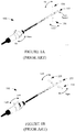
- Flexible ultrasound probes include an articulating portion that can be controllably articulated to move an end of the probe with a transducer array through an angle of up to ninety (90) degrees in one to four planes.
- Figures 1A and 1B show an example of a flexible probe 100; namely, a laparoscopic transducer type 8666, which is a product of BK-Medical ApS, a company of Herlev, Denmark, which is a wholly owned subsidiary of Analogic Corporation, a company of MA, USA.
- the probe 100 is configured to articulate between a zero position 102 and an up position 104 and a down position 106.
- the probe 100 is configured to articulate between the zero position 102 and a left position 108 and a right position 110.
- rigid probes are not configured to articulate as such and remain at the zero position 102.
- a lab probe can also be rigid in one direction, or only have motion in one plane. Furthermore this can be combined with a rotational motion of the array (i.e., can be combined with all the above).
- Tissue stiffness has been determined with ultrasound using a technique referred to as elasticity imaging.
- elasticity imaging a mechanical compression (e.g., via vibration) is applied to tissue, with the unhealthy tissue compressing less than the surrounding tissue since the strain is less than the surrounding tissue.
- the mechanical compression has been applied by having the user of the probe push the probe against tissue of interest in a fluctuating manner to compress (e.g., 1 mm or so) and decompress the tissue.
- the measured stiffness has been overplayed on top of the B-mode image.
- US 5351692 discloses an ultrasound probe having an elongate tubular member and an imaging ultrasonic transducer pivotally mounted proximate the distal end of the tubular member.
- the probe allows to manipulate the probe head to remain in contact with the tissue.
- US 2010/160778 discloses a method and apparatus for determining viscoelastic parameters of a tissue.
- a vibration signal is applied to the tissue and displacements at a plurality of locations within the tissue are measured at a plurality of times.
- an elongate ultrasound probe including a probe head with a transducer array, a handle, a flexor located between and affixed to the probe head and the handle, a flexor actuator configured to flex the flexor, and a probe head motion actuator configured to oscillate the flexor actuator and thereby oscillate the probe head.
- a method in another aspect, includes electronically vibrating a probe head, which includes a transducer array, of an ultrasound probe in connection with ultrasound elasticity imaging.
- an ultrasound imaging system in another aspect, includes an elongate ultrasound probe.
- the probe includes a probe head with a transducer array, a handle, a flexor located between and affixed to the probe head and the handle, and a flexor actuator configured to oscillate the flexor actuator and thereby oscillate the probe head, and electronics, internal to the handle, that controls at least the probe head motion actuator.
- an imaging system 202 such as ultrasound imaging system is schematically illustrated.
- the imaging system 202 includes an ultrasound probe 204 and a console 206.
- the probe 204 includes a handle 208, a shaft 210, an articulating member 212 and a probe head 214.
- the probe head 214 includes a transducer array 216, which includes one, two or three dimensional array transducer elements. Suitable configurations include, but are not limited to, linear, curved (e.g., convex), phased and matrix arrays.
- the transducer array 216 can be used to acquire data for A-mode, B-mode, etc. acquisitions, individually and in combination with color flow, Doppler flow, etc.
- the shaft 210 extends along a longitudinal axis 211 of the probe 204 and is geometrically configured to allow for moving and/or positioning the probe head 214 (and thus the transducer array 216 attached thereto) within a cavity, such as the abdomen or other cavity of a human patient, or a cavity of an object.
- the articulating member 212 is a generally flexible section of the probe 204.
- a first side 218 of the articulating member 212 is affixed to the probe head 214 and an opposing side 220 of the articulating member 212 is affixed to the shaft 210.
- a flexor 222 is controlled to flex the articulating member 212 to position the transducer array 216 between various positions in one to four planes through angles of up to one hundred and seventy (170) degrees and/or straight (zero degrees) along the longitudinal axis 211 of the probe 204. Examples of positions include those shown in connection with Figures 1A and 1B .
- the handle 208 includes a flexor actuator 224, a probe head motion actuator 226, and electronics 228.
- the flexor actuator 224 is configured to actuate the flexor 222 to move the head 214 and thus the transducer array 216 through the various angels discussed herein.
- Various approaches can be utilized to actuate the flexor 222.
- An example of a suitable manual approach is discussed in Figures 3A, 3B and 3C and used in connection with the laparoscopic transducer type 8666.
- the electronics 228 include circuitry for electronically controlling the flexor 222.
- the probe head motion actuator 226 is configured to translate the flexor 222 and hence the probe head 214 and transducer array 216, e.g., when the system 202 is operated in elasticity imaging mode, e.g., in connection with a laparoscopic or other procedure. As described in greater detail below, the probe head motion actuator 226 is incorporated with and controllably oscillates (or vibrates) the flexor actuator 224 in the handle 208, which oscillates the probe head 214 and transducer array 216. Such oscillating is well-suited for applying mechanical compression or vibration to tissue for elasticity imaging.
- the probe head motion actuator 226 can be controlled internally, for example, by the electronics 228 and/or by an external device. With either instance, the user and/or other personnel need only activate the motion actuator 226 to oscillate the transducer array 216, mitigating having to have the user manually push the probe head 214 against tissue of interest in a fluctuating manner to compress and decompress the tissue.
- This electronically controlled oscillation also facilitates applying suitable force at a suitable frequency in cavities with low to no visibility, such as with laparoscopic procedures. Examples of suitable frequencies are frequencies that will compress the tissue of interest up to two millimeters, such as 0.5 to 5.0 Hz.
- the electronics 228 are in electrical communication with the ultrasound transducer array 216 and are used to convey signals to the ultrasound transducer array 216 that actuate the individual transducer elements therein to produce ultrasound signals and receive signals therefrom corresponding to received echoes.
- the electronics 228 can reside outside of the ultrasound probe 204, for example, in connection with console 206 and/or elsewhere.
- the probe 204 can be used for laparoscopic, endoscopic, and/or other ultrasound applications, and can be used to assist personnel, for example, with an interventional procedure such as a liver, gall bladder, tumor biopsy, etc., guide personnel, for example, with RF ablation, chemical injection, etc. As shown, the probe 204 is employed with the console 206. In other embodiments, the probe 204 can be employed with other consoles and/or device, via cable or wireless communication.
- the console 206 includes a transmit circuit 232 that controls the phasing and/or time of actuation of the individual elements of the transducer array 216, which allows for steering and/or focusing the transmitted beam from predetermined origins along the array and at predetermined angles.
- the console 206 further includes a receive circuit 234 that receives signals indicative of the echoes received by the transducer array 216.
- the receive circuit 234 can beamform (e.g., delays and sums) the echoes into a sequence of focused, coherent echo samples along focused scanlines of a scanplane.
- the echoes include tissue motion or displacement information between the frames of data.
- a controller 236 controls the transmit circuit 232 and/or the receive circuit 234. Such control may include, but is not limited to, controlling the frame rate, number of scanline groups, transmit angles, transmit energies, transmit frequencies, transmit and/or receive delays, etc., and/or activating the motion actuator 226 for elasticity imaging.
- An echo processor 244 processes received echoes. Such processing includes beamforming (e.g., delay and sum) the echoes in connection with B-mode imaging, etc.
- a motion processor 246 extracts and processes the tissue motion information from the echoes in connection with elastography imaging. Other processing lowers speckle, improves specular reflector delineation, and/or includes FIR filtering, IIR filtering, etc.
- a scan converter 238 scan converts the frames of data to generate data for display, for example, by converting the data to the coordinate system of the display. This may include changing the vertical and/or horizontal scan frequency of signal based on the display. Furthermore, the scan converter 238 can be configured to employ analog and/or digital scan converting techniques.
- a rendering engine 248 is configured to at least generate elastography or other images based on the processed data.
- the elastography images can be visually presented, stored, conveyed to another device, and/or otherwise utilized.
- a display 240 presents the rendered data.
- a user interface 242 includes input and/or output devices for interacting with the controller 236, e.g., to select a data processing and presentation mode, a data acquisition mode (e.g., B-mode, elasticity imaging, etc.), initiate scanning, etc.
- the user interface 242 may include controls such as buttons, knobs, a keypad, a touch screen, etc.
- the user interface 242 may also include visual (e.g., LCD, LED, etc.) and/or audible displays.
- the probe 204 and the console 206 respectively include complementary electrical interfaces, which can be electrically connected via a cable, wireless communication, or the like.
- the electrical connection there between allows electrical signals to be conveyed back and forth between the probe 204 and the console 206.
- the relative size, shape and position of the various components of the system 202 are provided for explanatory purposes and are not limiting. In other embodiments, at least one of the size, shape and position of at least one of the components is different.
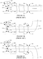
- Figures 3A, 3B and 3C schematically illustrate an example of prior art configuration of the flexor actuator 224 in connection with the handle 208, the shaft 210, the flexor 222, and the probe head 214.
- the flexor actuator 224 includes a cable 302. An end 304 of the cable 302 is affixed to a first portion 306 of the flexor 222.
- the flexor actuator 224 further includes a cable 308.
- An end 310 of the cable 308 is affixed to a second or opposing portion 312 (which opposes portion 306) of the flexor 222.
- Opposing ends 314 and 316 of the cables 302 and 308 are affixed to a movable member 318, with the end 314 of the cable 302 affixed to a first region 320 of the movable member 318 and the end 316 of the cable 308 affixed to second region 322 (which opposes the region 320) of the movable member 318.
- a shaft 328 is affixed to the movable member 318 and is configured to move the movable member 318.
- the movable member 318 is circular in shape and is affixed to rotate through a predetermined angle range or arc 324 about a rotational axis 326, the shaft 328 is affixed at the rotational axis 326, and moving the shaft 328 through range of the arc 324 rotates the moveable member 318 about the rotational axis 326.
- pivoting the shaft 328 away from the probe head 214 concurrently urges the second cable 308 in a direction towards the probe head 214 and pulls the first cable 302 in a direction away from the probe head 214.
- the flexor 222 is flexed such that the first portion 306 flexes away from the axis 211 and the second portion 312 flexes towards the axis 211. This is shown in Figure 3B .
- pivoting the shaft 328 towards the probe head 214 concurrently urges the first cable 302 in a direction towards the probe head 214 and pulls the second cable 308 in a direction away from the probe head 214.
- the flexor 222 is flexed such that the first portion 306 flexes towards the axis 211 and the second portion 312 flexes away from the axis 211. This is shown in Figure 3C .
- the shaft 328 When the shaft 328 is pivoted to a generally central position of the arc 324, the tension on the cables 302 and 308 is approximately equal, and the probe heads 214 extends axially along the axis 211. It is to be appreciated that location and/or length of the arc 324 is not limiting. In addition, the shaft 328 could be located on the opposing side and/or otherwise shaped.
- the moveable member 318 could instead be a slide mechanism, including two sliding members that linearly slide in opposing direction. In this manner, translating the moveable member 318 towards and away from the probe head 214 has a same effect as discussed above with respect to flexing the probe head 214.
- the motion actuator 226 includes an electro-mechanical device 400 with two guides 402 and 404 located in a housing 406 and configured to roll therein.
- one or more of the guides 402 and 404 rotates about a pin 408 (as shown).
- the guides 402 and 404 are free floating within the housing.
- the cable 302 is sandwiched between and physically contacts the guides 402 and 404.
- the guides 402 and 404 rotate, the guides 402 and 404 are set separated from each other so that the cable 302 can be fed there between.
- the guides 402 and 404 free floating, the guides 402 and 404 will move when installing the cable 302.
- the guides 402 and 404 When pivoting the shaft 328 as discussed above, for example, towards and away from the probe head 214, the guides 402 and 404 remain at a static location, but the guides 402 and 404 roll as the cable 302 translates there between towards and away from the probe head 214.
- a control portion 410 in response to an activation signal, automatically and electronically causes the guides 402 and 404 to oscillate, which causes the cable 302 to oscillate (translate back and forth, vibrate, etc.).
- the control portion 410 controllably oscillates the guides 402 and 404, for example, at a frequency suitable for elasticity imaging.
- the control portion 410 may include a device such as a piezoelectric vibration generator or the like.
- the electro-mechanical device 400 can be activated via a button, knob, slider, etc. located on the probe 204. Additionally or alternatively, the electro-mechanical device 400 can be activated via the console 206. Additionally or alternatively, the electro-mechanical device 400 can be activated via a remote control. Additionally or alternatively, the electro-mechanical device 400 can be activated via other device.
- Figures 5A and 5B show another example of the motion actuator 226.
- the motion actuator 226 includes a guide 502.
- the guide 502 is generally elliptical in shape, located at a fixed position, and configured to rotate about a pin 504.
- the guide 502 is located such that the guide 502 contacts the cable 302 at least when its long axis is perpendicular to the cable 302 ( Figure 5B ). In this manner, rotating the guide 502 will vary the force on the cable 302 as a function of rotation angle as the guide 502 rotates, creating an oscillation.
- the illustrated elliptical shape is not limiting.
- the member 502 can be any shape that will produce a varying force against the cable 302 while rotating the member 502, oscillating the cable 302. Examples of other shapes include triangular, rectangular, irregular, etc. More than one member 502 can be used can be used with the cable 302 and/or 308.
- Figures 6A and 6B show another example of the motion actuator 226.
- the motion actuator 226 includes a guide 602, which is in physical contact with the cable 302.
- An expandable/contractible chamber 604 is located adjacent to the guide 602. The chamber 604 is positioned such that when no fluid (e.g., air, gas, liquid, gel, etc.) is introduced into the chamber, either no or a minimum amount of force is exerted on the cable 302.
- no fluid e.g., air, gas, liquid, gel, etc.
- a fluid mover 606 moves a fluid (e.g., a liquid or gas) into and out of the chamber 604 via a pathway 608.
- the fluid mover 606 may include a manual or electric pump or the like which supplies and draws the fluid.
- the illustrated mover 606 is external. However, the mover 606 can alternatively be located in the probe 204. Similar to the mechanisms discussed above, the fluid mover 606 moves the cable 302 so as to apply a vibration to the cable 302 and have the probe head 214.
- the chamber 604 includes an egress port, which additionally or alternatively allows removal of the fluid from the chamber 604.
- Figure 6A shows an empty chamber 604 and Figure 6B shows a filled chamber 604.
- Figures 7A and 7B show another example of the motion actuator 226.
- a pushbutton including slidable element 702 that is slideably coupled within a track 704 and affixed to a guide 706.
- the pushbutton 700 exerts minimal (with respect to the force the guide 706 can exert on the cable 302) or no force on the cable.
- a fully pressed state Figure 7B
- the pushbutton 700 exerts a maximal (with respect to the force the guide 706 can exert on the cable 302) force on the cable 302.
- the force applied by the guide 706 fluctuates or varies as a function of the relative position of the slidable element 702 in the track 704.
- the slidable element 702 can be operated to move the cable 302 so as to apply a vibration to the cable 302 and have the probe head 214.
- Figures 8A and 8B show another example of the motion actuator 226.
- a rotating motor 802 drives a rod 804 that is connected via a joint 806 such as a ball-joint or the like to a rocker arm 808 that converts the rotating movement into up/down movements via pivoting the rocker arm 808 about a pivot 810, which oscillates the at least one cable.
- a joint 806 such as a ball-joint or the like
- rocker arm 808 that converts the rotating movement into up/down movements via pivoting the rocker arm 808 about a pivot 810, which oscillates the at least one cable.
- Figure 9 illustrates a method for employing the probe 204 in connection with elasticity imaging.
- the probe 204 is inserted into a cavity of a subject or object.
- the transducer array 216 is activated to emit ultrasound signals that traverse a field of view and an object or subject therein.
- the probe head motion activator 226 is activated to vibrate the probe head 214.
- the vibrating probe head causes a controlled fluctuating compression of the tissue.
- the transducer array 216 is activated to emit receive echoes produced in response to interaction with the object or subject.
- the console 206 processes the echoes, creating at least elasticity imaging information.
- the console 206 visually displays the elasticity imaging information. In one instance, this may include visually displaying a B or other mode image with the elasticity imaging information superimpose or overlayed thereon.
- the above may be implemented by way of computer readable instructions, encoded or embedded on computer readable storage medium such as physical memory or other non-transitory medium, which, when executed by a computer processor(s), cause the processor(s) to carry out the described acts. Additionally or alternatively, at least one of the computer readable instructions is carried by a signal, carrier wave or other transitory medium.
Landscapes
- Health & Medical Sciences (AREA)
- Life Sciences & Earth Sciences (AREA)
- Surgery (AREA)
- Medical Informatics (AREA)
- Biophysics (AREA)
- Pathology (AREA)
- Radiology & Medical Imaging (AREA)
- Engineering & Computer Science (AREA)
- Biomedical Technology (AREA)
- Heart & Thoracic Surgery (AREA)
- Physics & Mathematics (AREA)
- Molecular Biology (AREA)
- Nuclear Medicine, Radiotherapy & Molecular Imaging (AREA)
- Animal Behavior & Ethology (AREA)
- General Health & Medical Sciences (AREA)
- Public Health (AREA)
- Veterinary Medicine (AREA)
- Optics & Photonics (AREA)
- Gynecology & Obstetrics (AREA)
- Ultra Sonic Daignosis Equipment (AREA)
Claims (15)
- Längliche Ultraschallsonde (204), umfassend:einen Sondenkopf (214) mit einem Wandlerarray (216);einen Griff (208); undeinen Sondenkopf-Bewegungsantrieb (226), der dazu eingerichtet ist, den Sondenkopf in Oszillationsbewegung zu versetzen,dadurch gekennzeichnet, dass die Sonde weiter einen Beuger (222) umfasst, der sich zwischen dem Sondenkopf und dem Griff befindet und an diesen befestigt ist; undeinen Beugerantrieb (224) der dazu eingerichtet ist, den Beuger zu beugen, wobei der Sondenkopf-Bewegungsantrieb (226) dazu eingerichtet ist, den Beugerantrieb in Oszillationsbewegung zu versetzen, wodurch den Sondenkopf in Oszillationsbewegung versetzt wird.
- Sonde nach Anspruch 1, wobei der Sondenkopf-Bewegungsantrieb den Beugerantrieb in Oszillationsbewegung versetzt, um den Sondenkopf bei einer Frequenz für Ultraschall-Elastizitätsbildgebung in Oszillationsbewegung zu versetzen.
- Sonde nach einem der Ansprüche 1 bis 2, wobei der Beugerantrieb umfasst:wenigstens ein Kabel (302, 308), das an wenigstens einer Seite (306, 312) des Beugers befestigt ist, wobei der Sondenkopf-Bewegungsantrieb das wenigstens eine Kabel in Oszillationsbewegung versetzt, das das Kabel in Oszillationsbewegung versetzt, das den Sondenkopf in Oszillationsbewegung versetzt.
- Sonde nach Anspruch 3, wobei der Sondenkopf-Bewegungsantrieb umfasst:erste und zweite Führungen (402, 404), die das wenigstens eine Kabel zwischen denselben stützen und mit diesem in physischer Berührung stehen; undeinen Steuerabschnitt (410), der die erste und zweite Führung in Oszillationsbewegung versetzt, die das wenigstens eine Kabel in Oszillationsbewegung versetzt.
- Sonde nach Anspruch 4, wobei das Oszillieren der ersten und zweiten Führung einen Kraftbetrag, der durch die erste und zweite Führung an das wenigstens eine Kabel angelegt wird, schwanken lässt.
- Sonde nach einem der Ansprüche 4 bis 5, wobei der Steuerabschnitt durch wenigstens eines aus der Sonde, einer Ultraschallkonsole oder einer abgesetzten Vorrichtung aktiviert wird.
- Sonde nach einem der Ansprüche 4 bis 5, wobei der Steuerabschnitt elektronisch gesteuert ist.
- Sonde nach Anspruch 3, wobei der Sondenkopf-Bewegungsantrieb umfasst:eine Drehführung, die wenigstens zwei verschiedene lange Achsen besitzt, wobei das Drehen der Drehführung einen Kraftbetrag, der durch die Drehführung an das wenigstens eine Kabel angelegt wird, schwanken lässt, wodurch das wenigstens eine Kabel in Oszillationsbewegung versetzt wird.
- Sonde nach Anspruch 3, wobei der Sondenkopf-Bewegungsantrieb umfasst:einen Motor (802);eine Stange (804);ein Gelenk (806); undeinen Kipparm (808), wobei der Motor die Stange dreht, die mit dem Gelenk verbunden ist, das den Kipparm betätigt, wodurch die Drehbewegung in eine Auf-/Ab-Bewegung umgewandelt wird, die das wenigstens eine Kabel in Oszillationsbewegung versetzt.
- Sonde nach Anspruch 3, wobei der Sondenkopf-Bewegungsantrieb umfasst:eine Führung (602);eine Kammer (604), wobei die Kammer die Führung in physischer Berührung mit dem wenigstens einen Kabel stützt;eine Fluidbewegungseinrichtung (606), die der Kammer ein Fluid zuführt und das Fluid aus der Kammer abführt, was die Kammer dazu veranlasst, sich zu dehnen und zusammenzuziehen, wobei ein Kraftbetrag, der durch die Führung an das wenigstens eine Kabel angelegt wird, variiert, wodurch das wenigstens eine Kabel in Oszillationsbewegung versetzt wird.
- Sonde nach Anspruch 10, wobei sich die Fluidbewegungseinrichtung außerhalb der Sonde befindet.
- Sonde nach Anspruch 8 oder 10 bis 11, wobei die Fluidbewegungseinrichtung elektronisch gesteuert ist.
- Sonde nach Anspruch 3, wobei der Sondenkopf-Bewegungsantrieb umfasst:eine Führung (706);ein verschiebbares Element (702), wobei die verschiebbare Komponente die Führung in physischer Berührung mit dem wenigstens einen Kabel stützt;wobei das Eindrücken und Loslassen der verschiebbaren Komponente die Führung dazu veranlasst, einen Kraftbetrag, der durch die Führung an das wenigstens eine Kabel angelegt wird, zu variieren, wodurch das wenigstens eine Kabel in Oszillationsbewegung versetzt wird.
- Verfahren zur Ultraschall-Elastizitätsbildgebung, wobei das Verfahren das elektronische Vibrieren eines Sondenkopfes (214) einer Ultraschallsonde (204) umfasst, wobei der Sondenkopf (214) ein Wandlerarray (216) einschließt,
dadurch gekennzeichnet, dass das Verfahren weiter das Bewegen, in Antwort auf ein Signal, von wenigstens einer Führung umfasst, um einen Kraftbetrag, der an wenigstens eines von zwei an dem Sondenkopf (214) befestigten Kabeln angelegt wird, zu variieren, wodurch das wenigstens eine Kabel in Oszillationsbewegung versetzt wird, das den Sondenkopf (214) in Oszillationsbewegung versetzt. - Ultraschall-Bildgebungssystem (202), umfassend eine längliche Ultraschallsonde (204) nach Anspruch 1, und in dem Griff befindliche Elektronik (228), die wenigstens den Sondenkopf-Bewegungsantrieb steuert.
Applications Claiming Priority (1)
| Application Number | Priority Date | Filing Date | Title |
|---|---|---|---|
| PCT/IB2013/000043 WO2014108713A1 (en) | 2013-01-14 | 2013-01-14 | Laparoscopic ultrasound probe for elastographic imaging with automated oscillation mechanism |
Publications (2)
| Publication Number | Publication Date |
|---|---|
| EP2943111A1 EP2943111A1 (de) | 2015-11-18 |
| EP2943111B1 true EP2943111B1 (de) | 2017-10-18 |
Family
ID=47720547
Family Applications (1)
| Application Number | Title | Priority Date | Filing Date |
|---|---|---|---|
| EP13704631.4A Not-in-force EP2943111B1 (de) | 2013-01-14 | 2013-01-14 | Laparoskopische ultraschallsonde für elastografische bildgebung mit automatisiertem oszillationsmechanismus |
Country Status (3)
| Country | Link |
|---|---|
| US (2) | US10383598B2 (de) |
| EP (1) | EP2943111B1 (de) |
| WO (1) | WO2014108713A1 (de) |
Families Citing this family (2)
| Publication number | Priority date | Publication date | Assignee | Title |
|---|---|---|---|---|
| CN114190988B (zh) * | 2021-11-23 | 2024-10-15 | 中国科学院苏州生物医学工程技术研究所 | 一种能够空间定位的探头及三维图像构建方法 |
| US20250331926A1 (en) | 2024-04-24 | 2025-10-30 | GE Precision Healthcare LLC | Ultrasound imaging based medical device tracking |
Family Cites Families (10)
| Publication number | Priority date | Publication date | Assignee | Title |
|---|---|---|---|---|
| US5351692A (en) * | 1993-06-09 | 1994-10-04 | Capistrano Labs Inc. | Laparoscopic ultrasonic probe |
| CA2457376C (en) | 2003-10-14 | 2015-09-15 | The University Of British Columbia | Method for imaging the mechanical properties of tissue |
| WO2008016022A1 (en) * | 2006-07-31 | 2008-02-07 | Hitachi Medical Corporation | Pressing device, and ultrasonic probe and ultrasonic diagnosis device using the pressing device |
| US7496259B2 (en) * | 2007-01-02 | 2009-02-24 | University Of Washington | Endoscope with optical fiber and fiber optics system |
| US8323199B2 (en) | 2007-09-28 | 2012-12-04 | The University Of British Columbia | Method and apparatus for imaging the mechanical properties of tissue from an endocavity |
| US8052607B2 (en) * | 2008-04-22 | 2011-11-08 | St. Jude Medical, Atrial Fibrillation Division, Inc. | Ultrasound imaging catheter with pivoting head |
| US8394026B2 (en) | 2008-11-03 | 2013-03-12 | University Of British Columbia | Method and apparatus for determining viscoelastic parameters in tissue |
| US9089287B2 (en) * | 2008-12-30 | 2015-07-28 | St. Jude Medical, Atrial Fibrillation Division, Inc. | Image-guided ablation system and method for monitoring an ablation procedure |
| US20110166455A1 (en) * | 2010-01-07 | 2011-07-07 | Cully Edward H | Catheter |
| US20140039314A1 (en) * | 2010-11-11 | 2014-02-06 | The Johns Hopkins University | Remote Center of Motion Robot for Medical Image Scanning and Image-Guided Targeting |
-
2013
- 2013-01-14 US US14/760,550 patent/US10383598B2/en active Active
- 2013-01-14 WO PCT/IB2013/000043 patent/WO2014108713A1/en not_active Ceased
- 2013-01-14 EP EP13704631.4A patent/EP2943111B1/de not_active Not-in-force
-
2019
- 2019-07-02 US US16/459,860 patent/US20190321004A1/en not_active Abandoned
Non-Patent Citations (1)
| Title |
|---|
| None * |
Also Published As
| Publication number | Publication date |
|---|---|
| US20150335312A1 (en) | 2015-11-26 |
| EP2943111A1 (de) | 2015-11-18 |
| US20190321004A1 (en) | 2019-10-24 |
| WO2014108713A1 (en) | 2014-07-17 |
| US10383598B2 (en) | 2019-08-20 |
Similar Documents
| Publication | Publication Date | Title |
|---|---|---|
| US9897694B2 (en) | Ultrasound imaging probe | |
| US6645148B2 (en) | Ultrasonic probe including pointing devices for remotely controlling functions of an associated imaging system | |
| EP2353508B1 (de) | Ultraschallsonde | |
| JP5872460B2 (ja) | 改良された超音波変換器 | |
| EP1465531B1 (de) | Ultraschallabbildungssystem mit hoher frequenz und hoher einzelbildrate | |
| EP2050397A1 (de) | Ultraschallsonde | |
| JPH02195949A (ja) | 小型超音波プローブ | |
| EP3210649A1 (de) | Ultraschallsonde und ultraschallkopf damit | |
| CN107205622B (zh) | 超声成像探头 | |
| US11710229B2 (en) | Methods and systems for shear wave elastography | |
| EP3298967B1 (de) | Ultraschalldiagnosevorrichtung und verfahren zum betrieb davon | |
| EP2979644B1 (de) | Ultraschallsonde für punktionsnadel sowie diagnostische ultraschallvorrichtung damit | |
| US8568324B2 (en) | Systems and methods for mechanical translation of full matrix array | |
| US20190321004A1 (en) | Ultrasound Imaging Probe | |
| JPS61179138A (ja) | 操向可能なドツプラ−トランスデユ−サプロ−プ | |
| KR20250010731A (ko) | 휴대용 초음파 진단 장치 및 그 제어방법 | |
| CN114767162A (zh) | 瞬时弹性成像检测振动装置、探头、方法及系统 | |
| KR102171257B1 (ko) | 초음파 프로브 | |
| JP2009291269A (ja) | 超音波探触子及び超音波診断装置 | |
| WO2025241211A1 (zh) | 一种用于引导微创介入超声的方法及系统 | |
| JP6749270B2 (ja) | 超音波撮像プローブの操作方法 | |
| US10321847B2 (en) | Integrated tracking system for endocavity imaging | |
| JP2008278932A (ja) | 超音波プローブおよび超音波診断装置 | |
| KR20160064444A (ko) | 초음파 영상장치 | |
| JP2009131419A (ja) | 超音波診断装置。 |
Legal Events
| Date | Code | Title | Description |
|---|---|---|---|
| PUAI | Public reference made under article 153(3) epc to a published international application that has entered the european phase |
Free format text: ORIGINAL CODE: 0009012 |
|
| 17P | Request for examination filed |
Effective date: 20150727 |
|
| AK | Designated contracting states |
Kind code of ref document: A1 Designated state(s): AL AT BE BG CH CY CZ DE DK EE ES FI FR GB GR HR HU IE IS IT LI LT LU LV MC MK MT NL NO PL PT RO RS SE SI SK SM TR |
|
| AX | Request for extension of the european patent |
Extension state: BA ME |
|
| DAX | Request for extension of the european patent (deleted) | ||
| GRAP | Despatch of communication of intention to grant a patent |
Free format text: ORIGINAL CODE: EPIDOSNIGR1 |
|
| STAA | Information on the status of an ep patent application or granted ep patent |
Free format text: STATUS: GRANT OF PATENT IS INTENDED |
|
| INTG | Intention to grant announced |
Effective date: 20170510 |
|
| GRAS | Grant fee paid |
Free format text: ORIGINAL CODE: EPIDOSNIGR3 |
|
| GRAA | (expected) grant |
Free format text: ORIGINAL CODE: 0009210 |
|
| STAA | Information on the status of an ep patent application or granted ep patent |
Free format text: STATUS: THE PATENT HAS BEEN GRANTED |
|
| AK | Designated contracting states |
Kind code of ref document: B1 Designated state(s): AL AT BE BG CH CY CZ DE DK EE ES FI FR GB GR HR HU IE IS IT LI LT LU LV MC MK MT NL NO PL PT RO RS SE SI SK SM TR |
|
| REG | Reference to a national code |
Ref country code: GB Ref legal event code: FG4D |
|
| REG | Reference to a national code |
Ref country code: CH Ref legal event code: EP |
|
| REG | Reference to a national code |
Ref country code: AT Ref legal event code: REF Ref document number: 937218 Country of ref document: AT Kind code of ref document: T Effective date: 20171115 Ref country code: IE Ref legal event code: FG4D |
|
| REG | Reference to a national code |
Ref country code: DE Ref legal event code: R096 Ref document number: 602013028054 Country of ref document: DE |
|
| REG | Reference to a national code |
Ref country code: NL Ref legal event code: MP Effective date: 20171018 |
|
| REG | Reference to a national code |
Ref country code: LT Ref legal event code: MG4D |
|
| REG | Reference to a national code |
Ref country code: AT Ref legal event code: MK05 Ref document number: 937218 Country of ref document: AT Kind code of ref document: T Effective date: 20171018 |
|
| PG25 | Lapsed in a contracting state [announced via postgrant information from national office to epo] |
Ref country code: NL Free format text: LAPSE BECAUSE OF FAILURE TO SUBMIT A TRANSLATION OF THE DESCRIPTION OR TO PAY THE FEE WITHIN THE PRESCRIBED TIME-LIMIT Effective date: 20171018 |
|
| PG25 | Lapsed in a contracting state [announced via postgrant information from national office to epo] |
Ref country code: LT Free format text: LAPSE BECAUSE OF FAILURE TO SUBMIT A TRANSLATION OF THE DESCRIPTION OR TO PAY THE FEE WITHIN THE PRESCRIBED TIME-LIMIT Effective date: 20171018 Ref country code: ES Free format text: LAPSE BECAUSE OF FAILURE TO SUBMIT A TRANSLATION OF THE DESCRIPTION OR TO PAY THE FEE WITHIN THE PRESCRIBED TIME-LIMIT Effective date: 20171018 Ref country code: FI Free format text: LAPSE BECAUSE OF FAILURE TO SUBMIT A TRANSLATION OF THE DESCRIPTION OR TO PAY THE FEE WITHIN THE PRESCRIBED TIME-LIMIT Effective date: 20171018 Ref country code: SE Free format text: LAPSE BECAUSE OF FAILURE TO SUBMIT A TRANSLATION OF THE DESCRIPTION OR TO PAY THE FEE WITHIN THE PRESCRIBED TIME-LIMIT Effective date: 20171018 Ref country code: NO Free format text: LAPSE BECAUSE OF FAILURE TO SUBMIT A TRANSLATION OF THE DESCRIPTION OR TO PAY THE FEE WITHIN THE PRESCRIBED TIME-LIMIT Effective date: 20180118 |
|
| PGFP | Annual fee paid to national office [announced via postgrant information from national office to epo] |
Ref country code: DE Payment date: 20180122 Year of fee payment: 6 |
|
| PG25 | Lapsed in a contracting state [announced via postgrant information from national office to epo] |
Ref country code: HR Free format text: LAPSE BECAUSE OF FAILURE TO SUBMIT A TRANSLATION OF THE DESCRIPTION OR TO PAY THE FEE WITHIN THE PRESCRIBED TIME-LIMIT Effective date: 20171018 Ref country code: BG Free format text: LAPSE BECAUSE OF FAILURE TO SUBMIT A TRANSLATION OF THE DESCRIPTION OR TO PAY THE FEE WITHIN THE PRESCRIBED TIME-LIMIT Effective date: 20180118 Ref country code: GR Free format text: LAPSE BECAUSE OF FAILURE TO SUBMIT A TRANSLATION OF THE DESCRIPTION OR TO PAY THE FEE WITHIN THE PRESCRIBED TIME-LIMIT Effective date: 20180119 Ref country code: IS Free format text: LAPSE BECAUSE OF FAILURE TO SUBMIT A TRANSLATION OF THE DESCRIPTION OR TO PAY THE FEE WITHIN THE PRESCRIBED TIME-LIMIT Effective date: 20180218 Ref country code: RS Free format text: LAPSE BECAUSE OF FAILURE TO SUBMIT A TRANSLATION OF THE DESCRIPTION OR TO PAY THE FEE WITHIN THE PRESCRIBED TIME-LIMIT Effective date: 20171018 Ref country code: LV Free format text: LAPSE BECAUSE OF FAILURE TO SUBMIT A TRANSLATION OF THE DESCRIPTION OR TO PAY THE FEE WITHIN THE PRESCRIBED TIME-LIMIT Effective date: 20171018 Ref country code: AT Free format text: LAPSE BECAUSE OF FAILURE TO SUBMIT A TRANSLATION OF THE DESCRIPTION OR TO PAY THE FEE WITHIN THE PRESCRIBED TIME-LIMIT Effective date: 20171018 |
|
| REG | Reference to a national code |
Ref country code: DE Ref legal event code: R097 Ref document number: 602013028054 Country of ref document: DE |
|
| PG25 | Lapsed in a contracting state [announced via postgrant information from national office to epo] |
Ref country code: SK Free format text: LAPSE BECAUSE OF FAILURE TO SUBMIT A TRANSLATION OF THE DESCRIPTION OR TO PAY THE FEE WITHIN THE PRESCRIBED TIME-LIMIT Effective date: 20171018 Ref country code: EE Free format text: LAPSE BECAUSE OF FAILURE TO SUBMIT A TRANSLATION OF THE DESCRIPTION OR TO PAY THE FEE WITHIN THE PRESCRIBED TIME-LIMIT Effective date: 20171018 Ref country code: DK Free format text: LAPSE BECAUSE OF FAILURE TO SUBMIT A TRANSLATION OF THE DESCRIPTION OR TO PAY THE FEE WITHIN THE PRESCRIBED TIME-LIMIT Effective date: 20171018 Ref country code: CZ Free format text: LAPSE BECAUSE OF FAILURE TO SUBMIT A TRANSLATION OF THE DESCRIPTION OR TO PAY THE FEE WITHIN THE PRESCRIBED TIME-LIMIT Effective date: 20171018 |
|
| PLBE | No opposition filed within time limit |
Free format text: ORIGINAL CODE: 0009261 |
|
| STAA | Information on the status of an ep patent application or granted ep patent |
Free format text: STATUS: NO OPPOSITION FILED WITHIN TIME LIMIT |
|
| PG25 | Lapsed in a contracting state [announced via postgrant information from national office to epo] |
Ref country code: IT Free format text: LAPSE BECAUSE OF FAILURE TO SUBMIT A TRANSLATION OF THE DESCRIPTION OR TO PAY THE FEE WITHIN THE PRESCRIBED TIME-LIMIT Effective date: 20171018 Ref country code: SM Free format text: LAPSE BECAUSE OF FAILURE TO SUBMIT A TRANSLATION OF THE DESCRIPTION OR TO PAY THE FEE WITHIN THE PRESCRIBED TIME-LIMIT Effective date: 20171018 Ref country code: PL Free format text: LAPSE BECAUSE OF FAILURE TO SUBMIT A TRANSLATION OF THE DESCRIPTION OR TO PAY THE FEE WITHIN THE PRESCRIBED TIME-LIMIT Effective date: 20171018 Ref country code: RO Free format text: LAPSE BECAUSE OF FAILURE TO SUBMIT A TRANSLATION OF THE DESCRIPTION OR TO PAY THE FEE WITHIN THE PRESCRIBED TIME-LIMIT Effective date: 20171018 |
|
| REG | Reference to a national code |
Ref country code: CH Ref legal event code: PL |
|
| 26N | No opposition filed |
Effective date: 20180719 |
|
| GBPC | Gb: european patent ceased through non-payment of renewal fee |
Effective date: 20180118 |
|
| PG25 | Lapsed in a contracting state [announced via postgrant information from national office to epo] |
Ref country code: FR Free format text: LAPSE BECAUSE OF NON-PAYMENT OF DUE FEES Effective date: 20180131 Ref country code: LU Free format text: LAPSE BECAUSE OF NON-PAYMENT OF DUE FEES Effective date: 20180114 |
|
| REG | Reference to a national code |
Ref country code: IE Ref legal event code: MM4A |
|
| REG | Reference to a national code |
Ref country code: FR Ref legal event code: ST Effective date: 20180928 |
|
| REG | Reference to a national code |
Ref country code: BE Ref legal event code: MM Effective date: 20180131 |
|
| PG25 | Lapsed in a contracting state [announced via postgrant information from national office to epo] |
Ref country code: BE Free format text: LAPSE BECAUSE OF NON-PAYMENT OF DUE FEES Effective date: 20180131 Ref country code: CH Free format text: LAPSE BECAUSE OF NON-PAYMENT OF DUE FEES Effective date: 20180131 Ref country code: SI Free format text: LAPSE BECAUSE OF FAILURE TO SUBMIT A TRANSLATION OF THE DESCRIPTION OR TO PAY THE FEE WITHIN THE PRESCRIBED TIME-LIMIT Effective date: 20171018 Ref country code: LI Free format text: LAPSE BECAUSE OF NON-PAYMENT OF DUE FEES Effective date: 20180131 Ref country code: GB Free format text: LAPSE BECAUSE OF NON-PAYMENT OF DUE FEES Effective date: 20180118 |
|
| PG25 | Lapsed in a contracting state [announced via postgrant information from national office to epo] |
Ref country code: IE Free format text: LAPSE BECAUSE OF NON-PAYMENT OF DUE FEES Effective date: 20180114 |
|
| PG25 | Lapsed in a contracting state [announced via postgrant information from national office to epo] |
Ref country code: MC Free format text: LAPSE BECAUSE OF FAILURE TO SUBMIT A TRANSLATION OF THE DESCRIPTION OR TO PAY THE FEE WITHIN THE PRESCRIBED TIME-LIMIT Effective date: 20171018 |
|
| REG | Reference to a national code |
Ref country code: DE Ref legal event code: R119 Ref document number: 602013028054 Country of ref document: DE |
|
| PG25 | Lapsed in a contracting state [announced via postgrant information from national office to epo] |
Ref country code: DE Free format text: LAPSE BECAUSE OF NON-PAYMENT OF DUE FEES Effective date: 20190801 |
|
| PG25 | Lapsed in a contracting state [announced via postgrant information from national office to epo] |
Ref country code: MT Free format text: LAPSE BECAUSE OF NON-PAYMENT OF DUE FEES Effective date: 20180114 |
|
| PG25 | Lapsed in a contracting state [announced via postgrant information from national office to epo] |
Ref country code: TR Free format text: LAPSE BECAUSE OF FAILURE TO SUBMIT A TRANSLATION OF THE DESCRIPTION OR TO PAY THE FEE WITHIN THE PRESCRIBED TIME-LIMIT Effective date: 20171018 |
|
| PG25 | Lapsed in a contracting state [announced via postgrant information from national office to epo] |
Ref country code: PT Free format text: LAPSE BECAUSE OF FAILURE TO SUBMIT A TRANSLATION OF THE DESCRIPTION OR TO PAY THE FEE WITHIN THE PRESCRIBED TIME-LIMIT Effective date: 20171018 |
|
| PG25 | Lapsed in a contracting state [announced via postgrant information from national office to epo] |
Ref country code: HU Free format text: LAPSE BECAUSE OF FAILURE TO SUBMIT A TRANSLATION OF THE DESCRIPTION OR TO PAY THE FEE WITHIN THE PRESCRIBED TIME-LIMIT; INVALID AB INITIO Effective date: 20130114 Ref country code: MK Free format text: LAPSE BECAUSE OF NON-PAYMENT OF DUE FEES Effective date: 20171018 Ref country code: CY Free format text: LAPSE BECAUSE OF FAILURE TO SUBMIT A TRANSLATION OF THE DESCRIPTION OR TO PAY THE FEE WITHIN THE PRESCRIBED TIME-LIMIT Effective date: 20171018 |
|
| PG25 | Lapsed in a contracting state [announced via postgrant information from national office to epo] |
Ref country code: AL Free format text: LAPSE BECAUSE OF FAILURE TO SUBMIT A TRANSLATION OF THE DESCRIPTION OR TO PAY THE FEE WITHIN THE PRESCRIBED TIME-LIMIT Effective date: 20171018 |