EP2943177B1 - Ausgiesser für deckel - Google Patents
Ausgiesser für deckel Download PDFInfo
- Publication number
- EP2943177B1 EP2943177B1 EP13865798.6A EP13865798A EP2943177B1 EP 2943177 B1 EP2943177 B1 EP 2943177B1 EP 13865798 A EP13865798 A EP 13865798A EP 2943177 B1 EP2943177 B1 EP 2943177B1
- Authority
- EP
- European Patent Office
- Prior art keywords
- spout
- slit
- membrane
- conduit
- lid
- Prior art date
- Legal status (The legal status is an assumption and is not a legal conclusion. Google has not performed a legal analysis and makes no representation as to the accuracy of the status listed.)
- Not-in-force
Links
- 239000012528 membrane Substances 0.000 claims description 44
- 238000007373 indentation Methods 0.000 claims description 15
- 239000012530 fluid Substances 0.000 claims description 11
- 230000003014 reinforcing effect Effects 0.000 claims description 7
- 238000005728 strengthening Methods 0.000 claims description 6
- 239000013536 elastomeric material Substances 0.000 claims description 4
- 238000010276 construction Methods 0.000 description 4
- 235000013305 food Nutrition 0.000 description 4
- 230000001154 acute effect Effects 0.000 description 3
- 239000000463 material Substances 0.000 description 3
- 238000005336 cracking Methods 0.000 description 2
- 239000007788 liquid Substances 0.000 description 2
- 229920001296 polysiloxane Polymers 0.000 description 2
- 230000002028 premature Effects 0.000 description 2
- 239000010902 straw Substances 0.000 description 2
- 239000000126 substance Substances 0.000 description 2
- XLYOFNOQVPJJNP-UHFFFAOYSA-N water Substances O XLYOFNOQVPJJNP-UHFFFAOYSA-N 0.000 description 2
- 235000011437 Amygdalus communis Nutrition 0.000 description 1
- 241000220304 Prunus dulcis Species 0.000 description 1
- 235000020224 almond Nutrition 0.000 description 1
- 238000005452 bending Methods 0.000 description 1
- 230000015572 biosynthetic process Effects 0.000 description 1
- 150000001875 compounds Chemical class 0.000 description 1
- 239000012141 concentrate Substances 0.000 description 1
- 230000001419 dependent effect Effects 0.000 description 1
- 229910003460 diamond Inorganic materials 0.000 description 1
- 239000010432 diamond Substances 0.000 description 1
- 235000013350 formula milk Nutrition 0.000 description 1
- 235000011389 fruit/vegetable juice Nutrition 0.000 description 1
- 238000002347 injection Methods 0.000 description 1
- 239000007924 injection Substances 0.000 description 1
- 238000000034 method Methods 0.000 description 1
- 239000008267 milk Substances 0.000 description 1
- 235000013336 milk Nutrition 0.000 description 1
- 210000004080 milk Anatomy 0.000 description 1
- 238000012986 modification Methods 0.000 description 1
- 230000004048 modification Effects 0.000 description 1
- 230000035945 sensitivity Effects 0.000 description 1
- 235000013570 smoothie Nutrition 0.000 description 1
- 238000003860 storage Methods 0.000 description 1
- 239000011345 viscous material Substances 0.000 description 1
- 238000003466 welding Methods 0.000 description 1
- 235000013618 yogurt Nutrition 0.000 description 1
Images





Classifications
-
- B—PERFORMING OPERATIONS; TRANSPORTING
- B65—CONVEYING; PACKING; STORING; HANDLING THIN OR FILAMENTARY MATERIAL
- B65D—CONTAINERS FOR STORAGE OR TRANSPORT OF ARTICLES OR MATERIALS, e.g. BAGS, BARRELS, BOTTLES, BOXES, CANS, CARTONS, CRATES, DRUMS, JARS, TANKS, HOPPERS, FORWARDING CONTAINERS; ACCESSORIES, CLOSURES, OR FITTINGS THEREFOR; PACKAGING ELEMENTS; PACKAGES
- B65D47/00—Closures with filling and discharging, or with discharging, devices
- B65D47/04—Closures with discharging devices other than pumps
- B65D47/20—Closures with discharging devices other than pumps comprising hand-operated members for controlling discharge
- B65D47/2018—Closures with discharging devices other than pumps comprising hand-operated members for controlling discharge comprising a valve or like element which is opened or closed by deformation of the container or closure
- B65D47/2031—Closures with discharging devices other than pumps comprising hand-operated members for controlling discharge comprising a valve or like element which is opened or closed by deformation of the container or closure the element being formed by a slit, narrow opening or constrictable spout, the size of the outlet passage being able to be varied by increasing or decreasing the pressure
-
- A—HUMAN NECESSITIES
- A47—FURNITURE; DOMESTIC ARTICLES OR APPLIANCES; COFFEE MILLS; SPICE MILLS; SUCTION CLEANERS IN GENERAL
- A47G—HOUSEHOLD OR TABLE EQUIPMENT
- A47G19/00—Table service
- A47G19/22—Drinking vessels or saucers used for table service
- A47G19/2205—Drinking glasses or vessels
- A47G19/2266—Means for facilitating drinking, e.g. for infants or invalids
- A47G19/2272—Means for facilitating drinking, e.g. for infants or invalids from drinking glasses or cups comprising lids or covers
-
- B—PERFORMING OPERATIONS; TRANSPORTING
- B65—CONVEYING; PACKING; STORING; HANDLING THIN OR FILAMENTARY MATERIAL
- B65D—CONTAINERS FOR STORAGE OR TRANSPORT OF ARTICLES OR MATERIALS, e.g. BAGS, BARRELS, BOTTLES, BOXES, CANS, CARTONS, CRATES, DRUMS, JARS, TANKS, HOPPERS, FORWARDING CONTAINERS; ACCESSORIES, CLOSURES, OR FITTINGS THEREFOR; PACKAGING ELEMENTS; PACKAGES
- B65D47/00—Closures with filling and discharging, or with discharging, devices
- B65D47/04—Closures with discharging devices other than pumps
- B65D47/06—Closures with discharging devices other than pumps with pouring spouts or tubes; with discharge nozzles or passages
-
- A—HUMAN NECESSITIES
- A61—MEDICAL OR VETERINARY SCIENCE; HYGIENE
- A61J—CONTAINERS SPECIALLY ADAPTED FOR MEDICAL OR PHARMACEUTICAL PURPOSES; DEVICES OR METHODS SPECIALLY ADAPTED FOR BRINGING PHARMACEUTICAL PRODUCTS INTO PARTICULAR PHYSICAL OR ADMINISTERING FORMS; DEVICES FOR ADMINISTERING FOOD OR MEDICINES ORALLY; BABY COMFORTERS; DEVICES FOR RECEIVING SPITTLE
- A61J11/00—Teats
- A61J11/0035—Teats having particular shape or structure
- A61J11/0065—Teats having particular shape or structure for improving rigidity, e.g. anti-bite-through or anti-collapsing
-
- B—PERFORMING OPERATIONS; TRANSPORTING
- B65—CONVEYING; PACKING; STORING; HANDLING THIN OR FILAMENTARY MATERIAL
- B65D—CONTAINERS FOR STORAGE OR TRANSPORT OF ARTICLES OR MATERIALS, e.g. BAGS, BARRELS, BOTTLES, BOXES, CANS, CARTONS, CRATES, DRUMS, JARS, TANKS, HOPPERS, FORWARDING CONTAINERS; ACCESSORIES, CLOSURES, OR FITTINGS THEREFOR; PACKAGING ELEMENTS; PACKAGES
- B65D2547/00—Closures with filling and discharging, or with discharging, devices
- B65D2547/04—Closures with discharging devices other than pumps
- B65D2547/06—Closures with discharging devices other than pumps with pouring spouts ot tubes; with discharge nozzles or passages
- B65D2547/063—Details of spouts
- B65D2547/066—Details of spouts inserted in or attached to the base element
Definitions
- the invention relates to a spout for a lid according to the preamble of claim 1.
- this disclosure relates to a spout for a lid, where the lid can be adapted to fit over and close an open top of a container.
- a spout for a lid of the above-mentioned type is known, e.g. from DE 20 2006 012 915 U1 and US 2006/201902 A1 .
- the invention provides a spout for a lid having the features of claim 1. Further embodimens of the invention are described in the dependent claims.
- the lid may be adapted to fit over and close an open top of a container.
- the spout can include an elongated fluid conduit lying along a conduit longitudinal axis and having a pair of opposed convex curved sidewalls that meet at two opposed locations at an angle of less than 180 degrees to define a generally elliptical cross-sectional shape that has a major axis that passes through the sidewall meeting locations.
- a bite valve comprising a membrane is located within the conduit. The bite valve may be but need not be spaced from the ends of the conduit. The membrane is coupled to both walls and spans the conduit so as to fully block the conduit when the valve is not activated or opened by the user's action.
- the membrane can be but need not be generally dish-shaped or dome-shaped.
- a slit through the membrane lies along a slit axis that is preferably but not necessarily transverse to (e.g., normal to) the major axis of the conduit.
- the conduit sidewalls are essentially identical and the spout is a unitary part molded from an elastomeric material, preferably silicone.
- the membrane can have a top surface and a bottom surface, and the bite valve may further comprise a reinforcing ridge projecting outwardly from the bottom of the membrane.
- the slit may be generally linear when viewed from above.
- the reinforcing ridge may be co-linear with the slit.
- the slit may pass through the reinforcing ridge.
- the ridge may be generally semicircular in cross section.
- the ridge may be bisected by the slit.
- the spout may further comprise a pair of shallow indentations, one on the outside of each conduit sidewall and located at the approximate location of the slit.
- the spout further comprises two wall-strengthening ribs, one projecting inwardly from each of the sidewalls and both coupled to the top of the membrane.
- the ribs are centered on the slit.
- Each rib defines an indentation at the slit location. Each indentation may extend along at least most of the rib in the direction of the conduit longitudinal axis.
- the spout sidewalls may be essentially identical.
- the conduit and the bite valve may comprise a unitary part molded from an elastomeric material.
- the conduit may have a minor axis that is orthogonal to the major axis, and the slit may be co-linear with the minor axis. The slit may extend along most of the length of the minor axis.
- the bite valve may be symmetric about both the major axis and the minor axis.
- the membrane may be generally dome shaped.
- the membrane may be generally uniform in thickness, and along the minor axis the membrane may define an arc-shape.
- the membrane may be generally V-shaped.
- the lid may be convex, flat, or concave.
- the spout for a lid that is adapted to fit over and close an open top of a container are shown in the drawings.
- the spout is typically an integral part of a one-piece molded lid that is constructed and arranged to fit over and seal with the top lip of an open-top cup or other container.
- the lid can be injection molded from an elastomeric material such as a silicone compound.
- the lid can alternatively be made from more than one part with the parts coupled together through mechanical joints, ultrasonic welding, chemical bonding, or another adhesion method.
- containers that can be closed by such a lid are numerous and include sippy cups for use by young children (typically for fluids or purees), water bottles, and storage containers that need to be sealed so the contents do not spill, but from which the user desires to drink or otherwise ingest the contents.
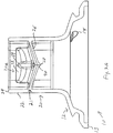
- Lid or cap 10 includes a lid body 12 which has lower rim 13 that is adapted to fit over and create a liquid-tight seal with the rim of a container (a non-limiting example of a container 150 is shown in figure 8 ) in a manner that is well known in the field and does not need to be further described.
- One-way valve or vent 14 allows air to enter into the container as fluid is withdrawn, to prevent the formation of a vacuum, as is also well known. Vent 14 is not essential to the function of the spout. Vent 14 allows the user to continuously drink from the spout - an intentionally designed feature. Without vent 14 the spout can be used until vacuum build up prevents the release of further liquid. At this point the user would need to crack the bite valve to allow the pressure in the cup to become equal with the ambient pressure.
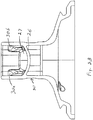
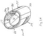
- Spout 20 is essentially an elongated fluid conduit 22 with an internal bite valve 21 that is adapted to be opened by the user via pressure applied to the outside of the spout through the lips, teeth and/or gums.
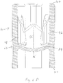
- Conduit 22 lies along longitudinal axis 23, figure 1 (axis 23 projects normal to the page in figure1 ).
- spout 20 is located vertically (i.e., axis 23 is vertical when lid 10 is located on a cup that is standing upright).
- spout 20 is located at the center of lid body 12.
- Conduit 22 is defined by opposed convex curved sidewalls 61 and 63 which meet at locations 64 and 65; sidewalls 61 and 63 are preferably but need not be essentially identical.
- sidewalls 61 and 63 and locations 64 and 65 are all portions of a continuous outer wall that is generally elliptically shaped and defines major axis 51 and minor axis 53.
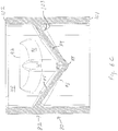
- Bite valve 21 comprises membrane 26 that is generally dish-shaped or generally dome-shaped; it lies along a curved plane that is convex toward the bottom of the conduit (i.e., toward the contents of the cup on which the lid is located).
- Membrane 26 presents a generally partially spherical bottom surface 29 that faces the fluid contents of the cup, and an opposed top surface 27 that faces the outside conduit end 24 which will be located in the user's mouth.
- membrane 26 is generally a partially spherical surface along the slit axis (or the projection of the minor axis), and is more generally "V"-shaped along major axis 51. These shapes generally describe this example of the membrane but the shape is not exactly geometric.
- Membrane 26 intersects sidewalls 61 and 63 at an acute angle 19 defined by lower or bottom surface 29 and conduit 22.
- Angle 19 may be but need not be approximately 60 degrees. By making the angle 19 smaller (less than 60 degrees), the valve will react faster, i.e., open and close in a more sensitive manner.
- the combination of angle 19 and the radius of curvature of membrane 26 helps to determine the speed and sensitivity at which the valve will open and shut as well as how widely the valve will physically open.
- the center of membrane 26 lying along minor axis 53 has a lower reinforcing ridge 28, which preferably is generally semi-circular in cross-section.
- a single slit 40 is made through membrane 26 and ridge 28 along the middle of ridge 28 to provide for valve 21 to be opened under use control, to allow the contents of the container to be dispensed through valve 21 into the user's mouth.
- Slit 40 preferably but not necessarily bisects both membrane 26 and ridge 28.
- ridge 28 as well as slit 40 are curved in one dimension and straight when viewed from above, and thus lie in a vertical plane that includes the minor axis.
- Spout 20 has on its outside shallow indentations 54 and 55 that serve as tactile locating elements for the user's lips. They are located approximately level with the location of membrane 26, preferably proximate the minor axis along which the slit lies. The center of each indentation 54, 55 may be positioned toward the ends of ridge 28. With this arrangement, when the user applies inward force by slightly closing the lips or mouth with the lips at the locations of indentations 54 and 55, sidewalls 61 and 63 are pushed closer together. This causes valve 21 to open.
- the depth of indentations 54 and 55 can be approximately 0.2mm, which is enough depth for the lips to register with the indentations.
- Wall-strengthening ribs 30a and 30b are located at each end of slit 40 and are both connected to the top of membrane 26 as well as to the inside of spout sidewalls 61 and 63.
- Ribs 30a and 30b have inwardly-facing surfaces 32 and 33, respectively, that when viewed from the top as in figures 1 and 3D are slightly concave relative to major axis 51.
- the faces of the ribs are shaped this way to both inhibit fatigue in the materials (stress fatigue), as well as to inhibit premature cracking of the valve when the proximal section of the valve is accidently hit or pinched slightly. Since the ribs project into the conduit from the walls, they also prevent collapse of the conduit due to suction force when the valve is being used.
- Ribs 30a and 30b are preferably identical and serve to add some rigidity to sidewalls 61 and 63 so that when the sidewalls are pressed together the bending force is concentrated at locations 64 and 65. This causes the valve to open more widely than it would without these ribs. Ribs 30a and 30b thicken sidewalls 61 and 63 to allow the collapse force to focus on valve 21 and not the area proximal to valve 21. Similarly, by strengthening the area proximal to valve 21, spout 20 will not collapse when the user sucks on spout 20. Ribs 30a and 30b each have fillets 35 and 37 that connect them to membrane 26 and the sidewall that the rib projects from.
- rib indentations 34 and 34a (which may be but need not be generally semi-circular) have their lower ends located co-linearly with slit 40 to help terminate slit 40 in a manner that inhibits its propagation as spout 20 is used.
- the semi circle shape of the indentations is a natural stress relief shape. The curve evenly distributes stress at that location, which inhibits the propagation of the slit (effectively the slit is like shear force tear).
- the semi-circular shape of ridge 28 helps to concentrate the forces applied to the underside or bottom surface 29 of membrane 26 by fluid in the cup when the cup is tilted such that fluid flows into the space just below membrane 26.
- the shape of ridge 28, along with the convex shape of bottom surface 29, allow the force of the fluid against the bottom of the membrane to push the two sides of membrane 26 together along slit 40, which helps to keep slit 40 closed so that the contents of the container are less likely to leak if the container is tipped over.
- Spout 80 is essentially the same as spout 20, except spout 80 is more pointed at its ends and is thus more almond or diamond shaped). Also, the wall strengthening ribs are shaped slightly differently.
- spout 80 is preferably symmetric about both the major axis (120) and minor axis (122) of conduit 81.
- Conduit 81 has top end 102 and lower end 101, which is coupled to the lid such as lid 140, figure 8 .
- Spout 80 includes spout sidewalls 110 and 112 that are convexly curved and meet at locations 111 and 113.
- Sidewalls 110 and 112 are slightly less convex than sidewalls 61 and 63, making the approximately oval cross-sectional shape of conduit 81 more pointed than that of conduit 22. Sidewalls 110 and 112 are thus a little less stiff than are sidewalls 61 and 63.
- This construction and arrangement makes valve 82 open with less force than valve 21, but the valve also opens a smaller amount and so may be more appropriate for less viscous substances than is valve 21.
- This construction also may make valve 82 close faster than valve 21 (presuming that the materials and the rest of the construction remains the same between the two valves), since the valve opens less.
- Membrane 84 has top surface 85 and bottom surface 86, which meets the inside of conduit 81 at an angle 103 that is acute and about 45 degrees.
- Ridge 88 is generally semi-circular in cross-section and lies along the slit axis, which is parallel to minor axis 122, as in the first example.
- the lowermost extent of membrane bottom or lower surface 86 may be closer to lower end 101 of conduit 81 than is the membrane 26 of the first example.
- the valve location could also be the top of a long straw.
- the conduit distal end 101 could extend into the cup, possibly several inches into a cup, like a straw.
- Wall-strengthening ribs 92 and 94 are located at each end of slit 90 and are connected to membrane 84 as well as to the inside of spout sidewalls 110 and 112. Ribs 92 and 94 have inwardly-facing surfaces 96 and 98 that when viewed from the top as in figure 6A are slightly convex relative to major axis 120. They are shaped this way to both inhibit fatigue in the materials (stress fatigue) and to inhibit premature cracking of the valve when the proximal section of the valve is accidently hit or pinched slightly. The ribs also inhibit collapse due to suction force when the valve is being used.
- rib indentations 95 and 97 are located co-linearly with slit 90 to help terminate slit 90 in a manner that inhibits its propagation as spout 80 is used.
- Indentations 114 and 116 are sized, shaped and located relative to the valve in the same or a similar manner as with spout 20.
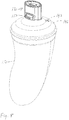
- Figure 8 depicts a non-limiting example of a cup or container 150 that carries the spout disclosed herein, in this case spout 130 located on lid 140 that has atmospheric vent 142. Also shown in this view is one of the lip locating features, 132.
- FIG. 9 illustrates that spout 160 herein can be located off-center of lid 170, which has atmospheric vent 172.
- This drawing also illustrates a different style of lid 170 that is flatter than lid 10.
- a flatter lid provides more depth between the end of the spout and the lid and thus more room for the nose and so may be easier and more comfortable to use.
- a flatter lid is less likely to collapse inwardly toward the bottom of the cup when a differential pressure exists between the bottom and top of the lid (e.g., when suction is applied by the child) as compared to the outwardly convex lid 10.
- FIGS 10A-10C illustrate another example of lid 200 with lid body 204 and spout 202, which in this example is located off-center of top 206 of lid body 204.
- Spout 202 has the same general construction as the previous examples, with concave membrane 220 that has a slit along its minor axis, to act as a bite valve.
- Lid body 204 has lower rim 208 that is coupled to a container (not shown), as with the other examples herein.
- Top 206 of lid body 204 in this example is concave, such that its central portion 212 is lower (i.e., closer to rim 208) than is its outer portion 213. The concavity provides even more room for the child's nose, and resists collapsing under differential pressure even more than the flat top lid described above.
Landscapes
- Engineering & Computer Science (AREA)
- Mechanical Engineering (AREA)
- Health & Medical Sciences (AREA)
- General Health & Medical Sciences (AREA)
- Pediatric Medicine (AREA)
- Closures For Containers (AREA)
Claims (13)
- Ausgießer (20) für einen Deckel (10), wobei der Deckel (10) derart aufgebaut und angeordnet ist, dass er über eine offene Oberseite eines Behälters (150) passt und diese verschließt, wobei der Ausgießer (20) aufweist:eine längserstreckte Fluidleitung (22), welche zwei Enden (24, 25) aufweist und entlang einer Leitungslängsachse (23) angeordnet ist, wobei die Leitung (22) ein Paar gegenüberliegender konvex gekrümmter Seitenwände (61, 63) aufweist, die in einem Winkel von weniger als 180 Grad an zwei gegenüberliegenden Positionen (64, 65) aufeinandertreffen, um eine im Allgemeinen elliptische Querschnittsform zu definieren, welche eine Hauptachse (51) aufweist, die durch die Seitenwand verläuft, an welcher die Positionen (64, 65) aufeinandertreffen; undein Beißventil (21), welches eine innerhalb der Leitung (22) angeordnete und von den Enden (24, 25) der Leitung beabstandete Membran (26), wobei die Membran (26) mit beiden Seitenwänden (61, 63) verbunden ist, um die Leitung (22) vollständig zu blockieren, und einen Schlitz (40) durch die Membran (26) aufweist, wobei der Schlitz (40) entlang einer Schlitzachse, die quer zur Hauptachse (51) der Leitung (22) verläuft, angeordnet ist;dadurch gekennzeichnet, dassder Ausgießer (20) ferner zwei Wandverstärkungsrippen (30a, 30b) aufweist, von denen jeweils eine von jeder der Seitenwände (61, 63) nach innen ragt und mit der Oberseite der Membran (26) verbunden ist;wobei die Rippen (30a, 30b) mittig auf dem Schlitz (40) angeordnet sind, wobei jede der Rippen (30a, 30b) eine Einbuchtung (34, 34a) an der Schlitzposition definiert, wobei sich jede der Einbuchtungen (34, 34a) in der Richtung der Leitungslängsachse (23) mindestens entlang eines Großteils der Rippe (30a, 30b) erstreckt.
- Ausgießer (20) nach Anspruch 1, wobei die Membran (26) eine obere Fläche (27) und eine untere Fläche (29) aufweist, und wobei das Beißventil (21) ferner einen Verstärkungssteg (28), der von der Unterseite der Membran (26) nach außen ragt, aufweist, wobei der Schlitz (40) im Allgemeinen gerade ist, wenn er von oben betrachtet wird, und der Verstärkungssteg (28) co-linear zu dem Schlitz angeordnet ist, wobei der Schlitz (40) durch den Verstärkungssteg (28) verläuft.
- Ausgießer (20) nach Anspruch 2, wobei der Steg (28) im Allgemeinen einen halbkreisförmigen Querschnitt aufweist.
- Ausgießer (20) nach Anspruch 1, ferner aufweisend ein Paar von flachen Einbuchtungen (54, 55), von denen jeweils eine an der Außenseite jeder Leitungsseitenwand (61, 63) und an der ungefähren Position des Schlitzes (40) angeordnet ist.
- Ausgießer (20) nach Anspruch 1, wobei die Seitenwände (61, 63) im Wesentlichen identisch sind.
- Ausgießer (20) nach Anspruch 1, wobei die Leitung (22) und das Beißventil (21) einen einheitlichen Abschnitt umfassen, der aus einem elastomeren Material geformt ist.
- Ausgießer (20) nach Anspruch 1, wobei die Leitung (22) eine Nebenachse (53) aufweist, die im rechten Winkel zur Hauptachse (51) angeordnet ist, und wobei der Schlitz (40) co-linear zu der Nebenachse (53) oder in einer vertikalen Ebene, welche die Nebenachse (53) einschließt, angeordnet ist.
- Ausgießer (20) nach Anspruch 7, wobei sich der Schlitz (40) entlang eines Großteils der Länge der Nebenachse (53) erstreckt.
- Ausgießer (20) nach Anspruch 7, wobei das Beißventil (21) sowohl um die Hauptachse (51) als auch um die Nebenachse (53) symmetrisch ist.
- Ausgießer (20) nach Anspruch 1, wobei die Membran (26) im Allgemeinen kuppelförmig ist.
- Ausgießer (20) nach Anspruch 10, wobei die Membran (26) im Allgemeinen eine einheitliche Dicke aufweist und die Membran (26) entlang der Nebenachse (53) eine Bogenform definiert.
- Ausgießer (20) nach Anspruch 11, wobei die Membran (26) entlang der Hauptachse (51) im Allgemeinen V-förmig ist.
- Ausgießer (20) nach Anspruch 1, wobei der Deckel (10) konvex, flach oder konkav ist.
Applications Claiming Priority (2)
| Application Number | Priority Date | Filing Date | Title |
|---|---|---|---|
| US201261738425P | 2012-12-18 | 2012-12-18 | |
| PCT/US2013/076109 WO2014100168A1 (en) | 2012-12-18 | 2013-12-18 | Spout for lid |
Publications (3)
| Publication Number | Publication Date |
|---|---|
| EP2943177A1 EP2943177A1 (de) | 2015-11-18 |
| EP2943177A4 EP2943177A4 (de) | 2016-10-26 |
| EP2943177B1 true EP2943177B1 (de) | 2019-02-20 |
Family
ID=50979149
Family Applications (1)
| Application Number | Title | Priority Date | Filing Date |
|---|---|---|---|
| EP13865798.6A Not-in-force EP2943177B1 (de) | 2012-12-18 | 2013-12-18 | Ausgiesser für deckel |
Country Status (6)
| Country | Link |
|---|---|
| US (1) | US10167119B2 (de) |
| EP (1) | EP2943177B1 (de) |
| CN (1) | CN105228574B (de) |
| AU (1) | AU2013361517B2 (de) |
| CA (1) | CA2902999C (de) |
| WO (1) | WO2014100168A1 (de) |
Cited By (1)
| Publication number | Priority date | Publication date | Assignee | Title |
|---|---|---|---|---|
| US11345523B2 (en) | 2018-05-31 | 2022-05-31 | Camelbak Products, Llc | Bite-actuated mouthpieces and drink vessels including bite-actuated mouthpieces |
Families Citing this family (10)
| Publication number | Priority date | Publication date | Assignee | Title |
|---|---|---|---|---|
| WO2015168701A1 (en) * | 2014-05-02 | 2015-11-05 | Munchkin, Inc. | Bite proof spout |
| US10124937B2 (en) | 2015-09-03 | 2018-11-13 | Helen Of Troy Limited | Lid assembly for drinking cup with integral hinge mount for cap |
| CN106510361B (zh) * | 2016-10-14 | 2018-04-06 | 淄博正邦知识产权企划有限公司 | 一种咬动式直饮双温杯 |
| USD871836S1 (en) | 2018-05-31 | 2020-01-07 | Camelbak Products, Llc | Bite-actuated mouthpiece |
| USD901238S1 (en) | 2018-05-31 | 2020-11-10 | Camelbak Products, Llc | Bite-actuated mouthpiece |
| TWI708719B (zh) * | 2019-02-13 | 2020-11-01 | 陳裕翔 | 吸嘴 |
| AU2019448719B2 (en) * | 2019-05-27 | 2023-08-31 | Beijing Shenchuang Century Information Technology Co., Ltd. | Anti-overflow pipe |
| CN110056671B (zh) * | 2019-05-27 | 2024-08-23 | 北京申创世纪信息技术有限公司 | 一种防溢流管 |
| CN111924314A (zh) * | 2020-08-28 | 2020-11-13 | 深圳市通产丽星科技集团有限公司 | 一种出液控制阀、可控制出液量的盖子及包装容器 |
| CN117179520A (zh) * | 2023-06-26 | 2023-12-08 | 杭州瑶宝婴童用品有限公司 | 一种防咬破、防吸瘪、控流、防脱嘴以及辅助咬合的直饮吸嘴 |
Family Cites Families (9)
| Publication number | Priority date | Publication date | Assignee | Title |
|---|---|---|---|---|
| US4690375A (en) * | 1986-07-07 | 1987-09-01 | Vorhis Daniel J | Self closing squeeze valve |
| US20030222238A1 (en) * | 2001-02-07 | 2003-12-04 | Getzewich Lee A. | Bite valve for personal hydration devices and a method for making the same |
| US6874760B2 (en) * | 2003-05-21 | 2005-04-05 | Eric S. Steckel | Angled-slit bite-valve |
| CN100464664C (zh) | 2004-03-19 | 2009-03-04 | 杨士圣 | 具有大开口状态的软式吸嘴制造方法 |
| US20060201902A1 (en) | 2005-03-03 | 2006-09-14 | Brown Craig E | Fully continuously vented drinking cup for infants and children |
| US7533783B2 (en) * | 2005-04-11 | 2009-05-19 | Camelbak Products, Llc | Drink bottles with bite-actuated mouthpieces |
| AT9419U1 (de) | 2005-09-01 | 2007-10-15 | Bamed Ag | Mundstück mit einem trinkschnabel |
| CN201640873U (zh) | 2009-07-01 | 2010-11-24 | 中山喜玛拉雅塑胶制品有限公司 | 吸嘴 |
| GB0916318D0 (en) * | 2009-09-17 | 2009-10-28 | Samson Ilan Z | Spout for a spill-proof beverage container |
-
2013
- 2013-12-18 CA CA2902999A patent/CA2902999C/en active Active
- 2013-12-18 CN CN201380073310.XA patent/CN105228574B/zh active Active
- 2013-12-18 US US14/766,472 patent/US10167119B2/en active Active
- 2013-12-18 EP EP13865798.6A patent/EP2943177B1/de not_active Not-in-force
- 2013-12-18 WO PCT/US2013/076109 patent/WO2014100168A1/en not_active Ceased
- 2013-12-18 AU AU2013361517A patent/AU2013361517B2/en not_active Ceased
Non-Patent Citations (1)
| Title |
|---|
| None * |
Cited By (2)
| Publication number | Priority date | Publication date | Assignee | Title |
|---|---|---|---|---|
| US11345523B2 (en) | 2018-05-31 | 2022-05-31 | Camelbak Products, Llc | Bite-actuated mouthpieces and drink vessels including bite-actuated mouthpieces |
| US12365519B2 (en) | 2018-05-31 | 2025-07-22 | Camelbak Products, Llc | Bite-actuated mouthpieces and drink vessels including bite-actuated mouthpieces |
Also Published As
| Publication number | Publication date |
|---|---|
| WO2014100168A1 (en) | 2014-06-26 |
| CA2902999A1 (en) | 2014-06-26 |
| CA2902999C (en) | 2017-12-19 |
| CN105228574B (zh) | 2018-08-31 |
| AU2013361517A1 (en) | 2015-10-01 |
| EP2943177A4 (de) | 2016-10-26 |
| US10167119B2 (en) | 2019-01-01 |
| HK1219649A1 (zh) | 2017-04-13 |
| EP2943177A1 (de) | 2015-11-18 |
| US20150368006A1 (en) | 2015-12-24 |
| CN105228574A (zh) | 2016-01-06 |
| AU2013361517B2 (en) | 2017-06-08 |
Similar Documents
| Publication | Publication Date | Title |
|---|---|---|
| EP2943177B1 (de) | Ausgiesser für deckel | |
| AU2005244643B2 (en) | Feeding bottle | |
| US6755318B2 (en) | Limited flow cups | |
| US8701928B2 (en) | Spout for a spill-proof beverage container | |
| US8622236B2 (en) | Drinking vessel usable in different orientations | |
| US8777028B2 (en) | Spout for drinking container | |
| CA2620375C (en) | Spill resistant closure | |
| US20220289438A1 (en) | Lid for a container | |
| US9609969B1 (en) | Deformable elastomeric valve and valve assembly | |
| JP2010536444A (ja) | 瓶用乳首 | |
| US9815592B2 (en) | Leak-free airless container having piston device | |
| EP1341430B1 (de) | Tasse mit begrenztem fluss | |
| JP2006192273A (ja) | 飲用ボトル、特に哺乳瓶用の乳首 | |
| KR102400215B1 (ko) | 안전 식음 빨대 | |
| US20060037963A1 (en) | Cup with a valve for drinking juice | |
| HK1219649B (en) | Spout for a lid | |
| WO2016031007A1 (ja) | 飲用容器 |
Legal Events
| Date | Code | Title | Description |
|---|---|---|---|
| PUAI | Public reference made under article 153(3) epc to a published international application that has entered the european phase |
Free format text: ORIGINAL CODE: 0009012 |
|
| 17P | Request for examination filed |
Effective date: 20150930 |
|
| AK | Designated contracting states |
Kind code of ref document: A1 Designated state(s): AL AT BE BG CH CY CZ DE DK EE ES FI FR GB GR HR HU IE IS IT LI LT LU LV MC MK MT NL NO PL PT RO RS SE SI SK SM TR |
|
| AX | Request for extension of the european patent |
Extension state: BA ME |
|
| RAP1 | Party data changed (applicant data changed or rights of an application transferred) |
Owner name: HELEN OF TROY LIMITED |
|
| DAX | Request for extension of the european patent (deleted) | ||
| A4 | Supplementary search report drawn up and despatched |
Effective date: 20160927 |
|
| RIC1 | Information provided on ipc code assigned before grant |
Ipc: A61J 11/04 20060101AFI20160921BHEP Ipc: B65D 47/06 20060101ALI20160921BHEP Ipc: A47G 19/22 20060101ALI20160921BHEP Ipc: A61J 11/00 20060101ALI20160921BHEP Ipc: B65D 47/20 20060101ALI20160921BHEP |
|
| RIC1 | Information provided on ipc code assigned before grant |
Ipc: A61J 11/04 20060101AFI20180813BHEP Ipc: A61J 11/00 20060101ALI20180813BHEP Ipc: A47G 19/22 20060101ALI20180813BHEP Ipc: B65D 47/20 20060101ALI20180813BHEP Ipc: B65D 47/06 20060101ALI20180813BHEP |
|
| GRAP | Despatch of communication of intention to grant a patent |
Free format text: ORIGINAL CODE: EPIDOSNIGR1 |
|
| STAA | Information on the status of an ep patent application or granted ep patent |
Free format text: STATUS: GRANT OF PATENT IS INTENDED |
|
| INTG | Intention to grant announced |
Effective date: 20180927 |
|
| GRAS | Grant fee paid |
Free format text: ORIGINAL CODE: EPIDOSNIGR3 |
|
| GRAA | (expected) grant |
Free format text: ORIGINAL CODE: 0009210 |
|
| STAA | Information on the status of an ep patent application or granted ep patent |
Free format text: STATUS: THE PATENT HAS BEEN GRANTED |
|
| AK | Designated contracting states |
Kind code of ref document: B1 Designated state(s): AL AT BE BG CH CY CZ DE DK EE ES FI FR GB GR HR HU IE IS IT LI LT LU LV MC MK MT NL NO PL PT RO RS SE SI SK SM TR |
|
| REG | Reference to a national code |
Ref country code: GB Ref legal event code: FG4D |
|
| REG | Reference to a national code |
Ref country code: CH Ref legal event code: EP |
|
| REG | Reference to a national code |
Ref country code: DE Ref legal event code: R096 Ref document number: 602013051214 Country of ref document: DE |
|
| REG | Reference to a national code |
Ref country code: AT Ref legal event code: REF Ref document number: 1097234 Country of ref document: AT Kind code of ref document: T Effective date: 20190315 |
|
| REG | Reference to a national code |
Ref country code: IE Ref legal event code: FG4D |
|
| REG | Reference to a national code |
Ref country code: NL Ref legal event code: MP Effective date: 20190220 |
|
| REG | Reference to a national code |
Ref country code: LT Ref legal event code: MG4D |
|
| PG25 | Lapsed in a contracting state [announced via postgrant information from national office to epo] |
Ref country code: NL Free format text: LAPSE BECAUSE OF FAILURE TO SUBMIT A TRANSLATION OF THE DESCRIPTION OR TO PAY THE FEE WITHIN THE PRESCRIBED TIME-LIMIT Effective date: 20190220 Ref country code: SE Free format text: LAPSE BECAUSE OF FAILURE TO SUBMIT A TRANSLATION OF THE DESCRIPTION OR TO PAY THE FEE WITHIN THE PRESCRIBED TIME-LIMIT Effective date: 20190220 Ref country code: LT Free format text: LAPSE BECAUSE OF FAILURE TO SUBMIT A TRANSLATION OF THE DESCRIPTION OR TO PAY THE FEE WITHIN THE PRESCRIBED TIME-LIMIT Effective date: 20190220 Ref country code: NO Free format text: LAPSE BECAUSE OF FAILURE TO SUBMIT A TRANSLATION OF THE DESCRIPTION OR TO PAY THE FEE WITHIN THE PRESCRIBED TIME-LIMIT Effective date: 20190520 Ref country code: PT Free format text: LAPSE BECAUSE OF FAILURE TO SUBMIT A TRANSLATION OF THE DESCRIPTION OR TO PAY THE FEE WITHIN THE PRESCRIBED TIME-LIMIT Effective date: 20190620 Ref country code: FI Free format text: LAPSE BECAUSE OF FAILURE TO SUBMIT A TRANSLATION OF THE DESCRIPTION OR TO PAY THE FEE WITHIN THE PRESCRIBED TIME-LIMIT Effective date: 20190220 |
|
| PG25 | Lapsed in a contracting state [announced via postgrant information from national office to epo] |
Ref country code: IS Free format text: LAPSE BECAUSE OF FAILURE TO SUBMIT A TRANSLATION OF THE DESCRIPTION OR TO PAY THE FEE WITHIN THE PRESCRIBED TIME-LIMIT Effective date: 20190620 Ref country code: BG Free format text: LAPSE BECAUSE OF FAILURE TO SUBMIT A TRANSLATION OF THE DESCRIPTION OR TO PAY THE FEE WITHIN THE PRESCRIBED TIME-LIMIT Effective date: 20190520 Ref country code: HR Free format text: LAPSE BECAUSE OF FAILURE TO SUBMIT A TRANSLATION OF THE DESCRIPTION OR TO PAY THE FEE WITHIN THE PRESCRIBED TIME-LIMIT Effective date: 20190220 Ref country code: RS Free format text: LAPSE BECAUSE OF FAILURE TO SUBMIT A TRANSLATION OF THE DESCRIPTION OR TO PAY THE FEE WITHIN THE PRESCRIBED TIME-LIMIT Effective date: 20190220 Ref country code: LV Free format text: LAPSE BECAUSE OF FAILURE TO SUBMIT A TRANSLATION OF THE DESCRIPTION OR TO PAY THE FEE WITHIN THE PRESCRIBED TIME-LIMIT Effective date: 20190220 Ref country code: GR Free format text: LAPSE BECAUSE OF FAILURE TO SUBMIT A TRANSLATION OF THE DESCRIPTION OR TO PAY THE FEE WITHIN THE PRESCRIBED TIME-LIMIT Effective date: 20190521 |
|
| REG | Reference to a national code |
Ref country code: AT Ref legal event code: MK05 Ref document number: 1097234 Country of ref document: AT Kind code of ref document: T Effective date: 20190220 |
|
| PG25 | Lapsed in a contracting state [announced via postgrant information from national office to epo] |
Ref country code: AL Free format text: LAPSE BECAUSE OF FAILURE TO SUBMIT A TRANSLATION OF THE DESCRIPTION OR TO PAY THE FEE WITHIN THE PRESCRIBED TIME-LIMIT Effective date: 20190220 Ref country code: ES Free format text: LAPSE BECAUSE OF FAILURE TO SUBMIT A TRANSLATION OF THE DESCRIPTION OR TO PAY THE FEE WITHIN THE PRESCRIBED TIME-LIMIT Effective date: 20190220 Ref country code: SK Free format text: LAPSE BECAUSE OF FAILURE TO SUBMIT A TRANSLATION OF THE DESCRIPTION OR TO PAY THE FEE WITHIN THE PRESCRIBED TIME-LIMIT Effective date: 20190220 Ref country code: EE Free format text: LAPSE BECAUSE OF FAILURE TO SUBMIT A TRANSLATION OF THE DESCRIPTION OR TO PAY THE FEE WITHIN THE PRESCRIBED TIME-LIMIT Effective date: 20190220 Ref country code: DK Free format text: LAPSE BECAUSE OF FAILURE TO SUBMIT A TRANSLATION OF THE DESCRIPTION OR TO PAY THE FEE WITHIN THE PRESCRIBED TIME-LIMIT Effective date: 20190220 Ref country code: RO Free format text: LAPSE BECAUSE OF FAILURE TO SUBMIT A TRANSLATION OF THE DESCRIPTION OR TO PAY THE FEE WITHIN THE PRESCRIBED TIME-LIMIT Effective date: 20190220 Ref country code: IT Free format text: LAPSE BECAUSE OF FAILURE TO SUBMIT A TRANSLATION OF THE DESCRIPTION OR TO PAY THE FEE WITHIN THE PRESCRIBED TIME-LIMIT Effective date: 20190220 Ref country code: CZ Free format text: LAPSE BECAUSE OF FAILURE TO SUBMIT A TRANSLATION OF THE DESCRIPTION OR TO PAY THE FEE WITHIN THE PRESCRIBED TIME-LIMIT Effective date: 20190220 |
|
| REG | Reference to a national code |
Ref country code: DE Ref legal event code: R097 Ref document number: 602013051214 Country of ref document: DE |
|
| PG25 | Lapsed in a contracting state [announced via postgrant information from national office to epo] |
Ref country code: SM Free format text: LAPSE BECAUSE OF FAILURE TO SUBMIT A TRANSLATION OF THE DESCRIPTION OR TO PAY THE FEE WITHIN THE PRESCRIBED TIME-LIMIT Effective date: 20190220 Ref country code: PL Free format text: LAPSE BECAUSE OF FAILURE TO SUBMIT A TRANSLATION OF THE DESCRIPTION OR TO PAY THE FEE WITHIN THE PRESCRIBED TIME-LIMIT Effective date: 20190220 |
|
| PLBE | No opposition filed within time limit |
Free format text: ORIGINAL CODE: 0009261 |
|
| STAA | Information on the status of an ep patent application or granted ep patent |
Free format text: STATUS: NO OPPOSITION FILED WITHIN TIME LIMIT |
|
| PG25 | Lapsed in a contracting state [announced via postgrant information from national office to epo] |
Ref country code: AT Free format text: LAPSE BECAUSE OF FAILURE TO SUBMIT A TRANSLATION OF THE DESCRIPTION OR TO PAY THE FEE WITHIN THE PRESCRIBED TIME-LIMIT Effective date: 20190220 |
|
| 26N | No opposition filed |
Effective date: 20191121 |
|
| PG25 | Lapsed in a contracting state [announced via postgrant information from national office to epo] |
Ref country code: SI Free format text: LAPSE BECAUSE OF FAILURE TO SUBMIT A TRANSLATION OF THE DESCRIPTION OR TO PAY THE FEE WITHIN THE PRESCRIBED TIME-LIMIT Effective date: 20190220 |
|
| PG25 | Lapsed in a contracting state [announced via postgrant information from national office to epo] |
Ref country code: TR Free format text: LAPSE BECAUSE OF FAILURE TO SUBMIT A TRANSLATION OF THE DESCRIPTION OR TO PAY THE FEE WITHIN THE PRESCRIBED TIME-LIMIT Effective date: 20190220 |
|
| REG | Reference to a national code |
Ref country code: DE Ref legal event code: R119 Ref document number: 602013051214 Country of ref document: DE |
|
| REG | Reference to a national code |
Ref country code: CH Ref legal event code: PL |
|
| PG25 | Lapsed in a contracting state [announced via postgrant information from national office to epo] |
Ref country code: MC Free format text: LAPSE BECAUSE OF FAILURE TO SUBMIT A TRANSLATION OF THE DESCRIPTION OR TO PAY THE FEE WITHIN THE PRESCRIBED TIME-LIMIT Effective date: 20190220 |
|
| PG25 | Lapsed in a contracting state [announced via postgrant information from national office to epo] |
Ref country code: IE Free format text: LAPSE BECAUSE OF NON-PAYMENT OF DUE FEES Effective date: 20191218 Ref country code: LU Free format text: LAPSE BECAUSE OF NON-PAYMENT OF DUE FEES Effective date: 20191218 Ref country code: FR Free format text: LAPSE BECAUSE OF NON-PAYMENT OF DUE FEES Effective date: 20191231 Ref country code: DE Free format text: LAPSE BECAUSE OF NON-PAYMENT OF DUE FEES Effective date: 20200701 |
|
| PG25 | Lapsed in a contracting state [announced via postgrant information from national office to epo] |
Ref country code: CH Free format text: LAPSE BECAUSE OF NON-PAYMENT OF DUE FEES Effective date: 20191231 Ref country code: LI Free format text: LAPSE BECAUSE OF NON-PAYMENT OF DUE FEES Effective date: 20191231 |
|
| PG25 | Lapsed in a contracting state [announced via postgrant information from national office to epo] |
Ref country code: CY Free format text: LAPSE BECAUSE OF FAILURE TO SUBMIT A TRANSLATION OF THE DESCRIPTION OR TO PAY THE FEE WITHIN THE PRESCRIBED TIME-LIMIT Effective date: 20190220 |
|
| PG25 | Lapsed in a contracting state [announced via postgrant information from national office to epo] |
Ref country code: HU Free format text: LAPSE BECAUSE OF FAILURE TO SUBMIT A TRANSLATION OF THE DESCRIPTION OR TO PAY THE FEE WITHIN THE PRESCRIBED TIME-LIMIT; INVALID AB INITIO Effective date: 20131218 Ref country code: MT Free format text: LAPSE BECAUSE OF FAILURE TO SUBMIT A TRANSLATION OF THE DESCRIPTION OR TO PAY THE FEE WITHIN THE PRESCRIBED TIME-LIMIT Effective date: 20190220 |
|
| PGFP | Annual fee paid to national office [announced via postgrant information from national office to epo] |
Ref country code: GB Payment date: 20211028 Year of fee payment: 9 |
|
| PGFP | Annual fee paid to national office [announced via postgrant information from national office to epo] |
Ref country code: BE Payment date: 20211119 Year of fee payment: 9 |
|
| PG25 | Lapsed in a contracting state [announced via postgrant information from national office to epo] |
Ref country code: MK Free format text: LAPSE BECAUSE OF FAILURE TO SUBMIT A TRANSLATION OF THE DESCRIPTION OR TO PAY THE FEE WITHIN THE PRESCRIBED TIME-LIMIT Effective date: 20190220 |
|
| GBPC | Gb: european patent ceased through non-payment of renewal fee |
Effective date: 20221218 |
|
| REG | Reference to a national code |
Ref country code: BE Ref legal event code: MM Effective date: 20221231 |
|
| PG25 | Lapsed in a contracting state [announced via postgrant information from national office to epo] |
Ref country code: GB Free format text: LAPSE BECAUSE OF NON-PAYMENT OF DUE FEES Effective date: 20221218 |
|
| PG25 | Lapsed in a contracting state [announced via postgrant information from national office to epo] |
Ref country code: BE Free format text: LAPSE BECAUSE OF NON-PAYMENT OF DUE FEES Effective date: 20221231 |