EP2943377B1 - Beleuchtung zur detektion von regentropfen auf einer scheibe mittels einer kamera - Google Patents
Beleuchtung zur detektion von regentropfen auf einer scheibe mittels einer kamera Download PDFInfo
- Publication number
- EP2943377B1 EP2943377B1 EP13827000.4A EP13827000A EP2943377B1 EP 2943377 B1 EP2943377 B1 EP 2943377B1 EP 13827000 A EP13827000 A EP 13827000A EP 2943377 B1 EP2943377 B1 EP 2943377B1
- Authority
- EP
- European Patent Office
- Prior art keywords
- camera
- structures
- light
- illumination
- shutter device
- Prior art date
- Legal status (The legal status is an assumption and is not a legal conclusion. Google has not performed a legal analysis and makes no representation as to the accuracy of the status listed.)
- Not-in-force
Links
Images


Classifications
-
- G—PHYSICS
- G01—MEASURING; TESTING
- G01W—METEOROLOGY
- G01W1/00—Meteorology
- G01W1/14—Rainfall or precipitation gauges
-
- B—PERFORMING OPERATIONS; TRANSPORTING
- B60—VEHICLES IN GENERAL
- B60S—SERVICING, CLEANING, REPAIRING, SUPPORTING, LIFTING, OR MANOEUVRING OF VEHICLES, NOT OTHERWISE PROVIDED FOR
- B60S1/00—Cleaning of vehicles
- B60S1/02—Cleaning windscreens, windows or optical devices
- B60S1/04—Wipers or the like, e.g. scrapers
- B60S1/06—Wipers or the like, e.g. scrapers characterised by the drive
- B60S1/08—Wipers or the like, e.g. scrapers characterised by the drive electrically driven
- B60S1/0818—Wipers or the like, e.g. scrapers characterised by the drive electrically driven including control systems responsive to external conditions, e.g. by detection of moisture, dirt or the like
- B60S1/0822—Wipers or the like, e.g. scrapers characterised by the drive electrically driven including control systems responsive to external conditions, e.g. by detection of moisture, dirt or the like characterized by the arrangement or type of detection means
- B60S1/0833—Optical rain sensor
- B60S1/0844—Optical rain sensor including a camera
-
- G—PHYSICS
- G01—MEASURING; TESTING
- G01N—INVESTIGATING OR ANALYSING MATERIALS BY DETERMINING THEIR CHEMICAL OR PHYSICAL PROPERTIES
- G01N21/00—Investigating or analysing materials by the use of optical means, i.e. using sub-millimetre waves, infrared, visible or ultraviolet light
- G01N21/17—Systems in which incident light is modified in accordance with the properties of the material investigated
-
- G—PHYSICS
- G01—MEASURING; TESTING
- G01N—INVESTIGATING OR ANALYSING MATERIALS BY DETERMINING THEIR CHEMICAL OR PHYSICAL PROPERTIES
- G01N21/00—Investigating or analysing materials by the use of optical means, i.e. using sub-millimetre waves, infrared, visible or ultraviolet light
- G01N21/17—Systems in which incident light is modified in accordance with the properties of the material investigated
- G01N21/25—Colour; Spectral properties, i.e. comparison of effect of material on the light at two or more different wavelengths or wavelength bands
- G01N21/255—Details, e.g. use of specially adapted sources, lighting or optical systems
-
- G—PHYSICS
- G01—MEASURING; TESTING
- G01N—INVESTIGATING OR ANALYSING MATERIALS BY DETERMINING THEIR CHEMICAL OR PHYSICAL PROPERTIES
- G01N21/00—Investigating or analysing materials by the use of optical means, i.e. using sub-millimetre waves, infrared, visible or ultraviolet light
- G01N21/17—Systems in which incident light is modified in accordance with the properties of the material investigated
- G01N21/41—Refractivity; Phase-affecting properties, e.g. optical path length
- G01N21/43—Refractivity; Phase-affecting properties, e.g. optical path length by measuring critical angle
-
- G—PHYSICS
- G01—MEASURING; TESTING
- G01N—INVESTIGATING OR ANALYSING MATERIALS BY DETERMINING THEIR CHEMICAL OR PHYSICAL PROPERTIES
- G01N21/00—Investigating or analysing materials by the use of optical means, i.e. using sub-millimetre waves, infrared, visible or ultraviolet light
- G01N21/17—Systems in which incident light is modified in accordance with the properties of the material investigated
- G01N21/41—Refractivity; Phase-affecting properties, e.g. optical path length
- G01N21/43—Refractivity; Phase-affecting properties, e.g. optical path length by measuring critical angle
- G01N2021/435—Sensing drops on the contact surface
Definitions
- the invention relates to a device for detecting rain on a pane by means of a light source and a camera.
- a rain sensor is proposed by means of a camera, which provides a large-area illumination of the passage window of the camera opening angle with the disk by an infrared diode.
- the camera is almost focused on infinity and thus simultaneously usable for driver assistance applications. Because of the image on the far field, raindrops are only noticeable as disturbances in the image, which are detected by complex differential measurements of the images recorded in synchronization with the pixel clock pulsed or modulated infrared light.
- a camera is placed behind a disk, especially inside a vehicle behind a windshield, and focused on a far-end area that lies in front of the disk.
- An illumination source for generating at least one light beam directed onto the pane directs the at least one light beam onto the pane such that at least one beam reflected from the outside of the pane impinges on the camera as an external light reflection or external reflection.
- the amount of light of at least one on the camera incident beam or light reflection can be measured by the camera.
- the illumination source can generate light in the visible wavelength range. It must be ensured that road users are not disturbed by the lighting. For this purpose, the intensity and duration of the illumination can be adapted to the external brightness.
- the post-published WO 2013/09169 A1 shows a device for detecting moisture on a vehicle window, which has a camera device and a radiation source for emitting optical radiation, such as an LED, on the windshield.
- the radiation source can be arranged on a printed circuit board within a recess of a lens hood of the camera device.
- the object of the present invention is to overcome the mentioned difficulties of the devices known from the prior art and to provide an optimized illumination for a camera-based rain detection.
- Lighting in the visible wavelength range offers the advantage that conventional driver assistance cameras with color resolution can completely capture this spectral range, while infrared light usually does not pass the usual for optimized color resolution infrared cut filter and thus can not be detected by these driver assistance cameras.
- the light exit surface is particularly visible laterally due to the broad emission angle.
- a device for detecting rain comprises a camera and an illumination source for emitting visible light onto a pane.
- the camera and the illumination source are designed and arranged such that the camera can detect a signal from the visible light which emits the illumination source onto the pane.
- the signal detected by the camera correlates with visible light of the illumination source reflected or scattered on the inside or outside of the pane and / or on the raindrop.
- the visible light passes through an aperture device that causes the light to be blocked or greatly attenuated in a given direction perpendicular to the direction of illumination by structures of the aperture device.
- a strong weakening occurs in particular when a maximum of 10% of the amount of light without the aperture device can propagate in the blocked-off direction.
- the aperture device preferably acts like a venetian blind. It allows the light to pass very well in a given direction, while the light is blocked away from the blinds by the slats transversely to this direction.
- the diaphragm device is arranged between the illumination source and the outer side of the disc and brings about the already explained effect that the propagation of the light in a predetermined transverse direction is reduced or prevented, preferably in this transverse direction to both sides (ie in positive as well as in negative direction).
- the camera preferably comprises an image sensor, e.g. a CCD or CMOS sensor, and an imaging system for focusing electromagnetic radiation from one or more areas onto the image sensor.
- an image sensor e.g. a CCD or CMOS sensor
- an imaging system for focusing electromagnetic radiation from one or more areas onto the image sensor.
- the illumination source may be formed as one or more light-emitting diodes (LEDs) or as a light band.
- LEDs light-emitting diodes
- the illumination source generates a planar illumination.
- rain is detected on the outside of the disk by placing the camera behind the disk and focusing it on a distant area in front of the disk.
- At least one light beam is advantageously generated by the illumination source and directed onto the pane such that at least one beam reflected from the outside of the pane impinges on the camera.
- the light reflection (s) of the at least one beam reflected from the outside of the pane is measured by means of the camera and the measured light reflection (s) of the at least one beam reflected from the outside of the pane for the detection of rain evaluated on the outside of the disc.
- the pane is the windshield of a vehicle and the predetermined (blocking) direction is perpendicular to the illumination direction and perpendicular to the vehicle longitudinal direction or corresponds to the vehicle transverse direction.
- the diaphragm device comprises or is a grating which comprises fins as structures.
- the camera comprises a viewing funnel or a screen or a scattered light diaphragm, which in particular limits the field of view of the camera (downwards) and ideally minimizes disturbing and stray light reflections.
- the diaphragm device is arranged on the view funnel or integrated in the view funnel.
- the illumination source can preferably be arranged below the view funnel.
- the view funnel is preferred in the region through which the light beam passes from the illumination source to the disk, transmissive to visible light.
- the diaphragm device can advantageously be integrated into the sight funnel in such a way that it "replaces" the sight funnel in this area.
- the view funnel may comprise a region of translucent material, and the aperture device may be disposed below or on it, for example.
- the structures of the diaphragm device are arranged parallel to each other, wherein they may each additionally have identical distances from each other (arranged equidistantly).
- the structures of the diaphragm device which is arranged in or on the view funnel, can be arranged adapted to the geometry of the surface of the viewing funnel.
- the surface of a sight funnel is usually not rectangular, but symmetrical trapezoidal. Therefore, the structures can advantageously not be arranged exactly parallel, but in such a way that they divide the view funnel in the same direction in the same direction areas or paths.
- adjacent structures of the diaphragm device can have a distance of less than 100 ⁇ m, ie in the micrometer range.
- Lattices with this structure size are already available, for example, as screen filters for computer displays; they can advantageously be produced as thin films.
- adjacent structures of the diaphragm device may advantageously have a distance in the range of 0.1 mm to 1 mm, that is to say in the millimeter range.
- the advantage of larger structures is that they can be produced using injection molding technology.
- the production of the grid can then even be advantageously combined with the manufacturing process of a light guide, which can also be produced in injection molding technology, in a two-component injection molding process.
- the required height of the grating or the diaphragm device results from simple geometrical considerations of the structure width and slat height. For example, in the case of a ratio of structural bridge to lamella height of 1: 1 with infinitely thin lamellae with absorptivity 1, the lateral emission angle transversely to the lamellar structure is limited to 45 °. This lateral radiation limitation is already completely sufficient for the intended purpose of optical interference suppression.
- the height of the structures is approximately equal to the distance of the structures of the diaphragm device.
- the diaphragm device is designed such that the spacing of adjacent structures or the width of the individual structures varies periodically. This achieves a spatial modulation of the illumination.
- a light guide is arranged on the illumination source.
- the aperture device is then arranged on the light guide.
- Fig. 1 shows in longitudinal section a focused on the far field camera (1) and an illumination source (3), the light (h, n) in the visible wavelength range on a disc (2) emits.
- the beam paths (h, n, t1, r1, t2 ', r2') explained below are shown schematically.
- the opening angle of the illumination is so large that rays reflected by a secondary beam (n) on the inside (2.1) and outside (2.2) of the disc are separated as two spatially separated beams (r1, r2 ') on the lens or the camera ( 1). Because of the focus on the far field is the border of the beam only blurred on the image chip (5) shown. Both beams (r1, r2 ') are sufficiently separated and their respective light reflections are measurable with the image sensor (5).
- the portion (r1) of the secondary beam (n) reflected at the air-disk interface (or disk inside (2.1)) can serve as a reference beam. From the portion which is transmitted (t1) into the disk, the portion serves as measuring beam (r2 ') which is reflected at the disk-raindrop interface (or disk outside (2.2)) and hits the camera (1). Not shown is the proportion of the beam, which is reflected several times within the disc (2) (on the inside (2.1) disc-air after it has been reflected on the outside (2.2) disc raindrops).
- the signal (r2') which is reduced in the rainfall (4) can be measured so easily and a windshield wiper can be correspondingly driven.
- the illumination source (3) with a wide radiation angle can be integrated in the present arrangement into the camera (1), more precisely into the camera body, e.g. placed as shown on a circuit board (16) of the camera module.
- the illumination source (3) is arranged here below a screen or a sight funnel (14).
- the view funnel (14) is transparent to visible light in the region through which the light beam (s) from the illumination source (3) passes to the disc (2).
- the raindrop (4) causes a stronger coupling (t2 ') of light from the disc in the area in front of the disc.
- the camera (1) measures a reduced intensity of the partial beam (r2 ') which has been reflected on the outside (2.2) of the pane (2).
- the illumination source (3) Since the illumination source (3) generates visible light (h, n) in a broad emission angle, the light exit surface is in particular laterally due to the broad emission angle, meaning here perpendicular to the longitudinal section plane of FIG Fig. 1 , visible, noticeable. As a result, other road users, such as passers-by who are laterally next to a vehicle in the amount of (windscreen) disc can be irritated.
- Fig. 2 shows in the upper part (6) of the image sensor (5), which serves the rain detection, seven pairs of illumination reflections (8, 9), which are generated for example by seven LEDs as the illumination source (3). These are due to the focus on infinity camera (1) not sharply displayed but perceptible. In particular, the light intensity or quantity can be measured.
- the upper illumination reflections (8) are generated by beams (r1) reflected on the inside (2.1) of the windshield (2), which generates lower (9) of beams (r2 ') reflected on the outside (2.2) of the windshield.
- Fig. 2 Thus, an exemplary division of the driver assistance area (7) and the rain sensor area (6) on the image chip (5). Both areas detect light (electromagnetic radiation) in the visible wavelength range and typically overlap in the rain sensor area (6).
- the illumination reflections from the outer windshield (9) over which a raindrop (4) lies are attenuated in intensity. These illuminating reflections (9) originate from rays (r2 ') reflected on the outside (2.2) of the windshield (2) and are of reduced intensity because a large part of the beam (t1) transmitted into the windshield (2) is separated by raindrops (4). decoupled from the windshield (t2 ') and thus not reflected back to the camera (1) (r2') is. These illumination reflections (9) thus carry the information in themselves, whether rain (4) on the outside (2.2) of the disc (2) is present, and their Light quantity or distribution pattern could be used alone as a measurement signal.
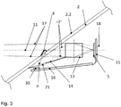
- FIG. 3 An embodiment of the invention is in Fig. 3 shown as a longitudinal section.
- the basic arrangement and design of the illumination source (3), disc (2) and camera (1) corresponds to the in Fig. 1 illustrated arrangement.
- the camera (1) shown here comprises an image sensor (5), two printed circuit boards (15, 16), an objective or imaging system (13) and a viewing funnel (14).
- the image sensor (5) is arranged on a first printed circuit board (15), which is connected to a second printed circuit board (16).
- the view funnel (14) limits the field of view of the camera (1).
- Fig. 3 Based on the schematic representation of Fig. 3 It can be seen how the remote area is imaged by the imaging system (13) or lens focused on the image sensor (5) of the camera (1).
- the beam path of the long range imaging (17) is shown schematically by dotted lines.
- the beam path (n, r2 ') of the illumination or Nah Schlsab Struktur is shown schematically by dashed lines.
- the focal point (18) of the image of the illumination rays (r2 ') reflected on the outside of the pane (2.2) lies behind the image sensor (5). Therefore, these illumination reflexes (9) in the camera image are out of focus.
- illumination source (3) serves in this embodiment, a plurality of light-emitting diodes (LEDs) (30), which in a row lying on the second circuit board (16) are arranged.
- a grid is applied as the diaphragm device (20).
- the grid is integrated in the funnel (14).
- the louvers (21) of the grid (20) are designed and arranged such that little or no light from the LEDs (30) perpendicular to the plane corresponding to the illustrated longitudinal section, out of the camera (1) or from the disc (2) can emerge.
- the grating louvers (21) may be arranged, for example, parallel to the dot-dashed optical axis (11) of the camera (1).
- Fig. 4 shows a plan view of a preparetrichters (14) with four underlying LEDs (30), which are arranged in a row.
- a grid is provided as the diaphragm device (20), which is integrated in the view funnel (14).
- louvers are provided as diaphragm structures (21), which, however, are not arranged exactly parallel to one another or aligned with respect to the optical axis, but are adapted to the geometry of the surface of the viewing funnel (14).
- This lamellar arrangement causes the light perpendicular to the optical axis (11), ie in Fig. 4 up and down, is blocked by the slats (21) of the grid (20).
- the grating louvers (21) allow the passage of the visible light (s) generated by the LEDs (30) through the viewing funnel (14) onto the pane (2).
- Fig. 5 finally shows an alternative embodiment of a lighting source (3) with light-emitting diodes (30), light guide (19) and grid (20).
- Fig. 5a shows the top view and Fig. 5b the cross section of this arrangement.
- a light guide (19) is arranged on the four light-emitting diodes (30) arranged next to one another.
- the grid is as a diaphragm structure (20).
- the lamellae (21) of the grating (20) are arranged parallel to one another and are preferably aligned parallel to the optical axis (11) of the camera (1).
- the lamellae (21) and the grid (20) can be produced for example by means of injection molding technology.
- the production of the grid (20) can then even be advantageously combined with the manufacturing process of the optical fiber (19), which can also be produced by injection molding, in a two-component injection molding process.
Landscapes
- Life Sciences & Earth Sciences (AREA)
- Physics & Mathematics (AREA)
- Health & Medical Sciences (AREA)
- Chemical & Material Sciences (AREA)
- Analytical Chemistry (AREA)
- Biochemistry (AREA)
- General Health & Medical Sciences (AREA)
- General Physics & Mathematics (AREA)
- Immunology (AREA)
- Pathology (AREA)
- Engineering & Computer Science (AREA)
- Environmental & Geological Engineering (AREA)
- Hydrology & Water Resources (AREA)
- Atmospheric Sciences (AREA)
- Biodiversity & Conservation Biology (AREA)
- Ecology (AREA)
- Environmental Sciences (AREA)
- Automation & Control Theory (AREA)
- Mechanical Engineering (AREA)
- Spectroscopy & Molecular Physics (AREA)
- Investigating Or Analysing Materials By Optical Means (AREA)
- Studio Devices (AREA)
- Lighting Device Outwards From Vehicle And Optical Signal (AREA)
Description
- Die Erfindung betrifft eine Vorrichtung zur Erkennung von Regen auf einer Scheibe mittels einer Beleuchtungsquelle und einer Kamera.
- In der
US 7,259,367 B2 wird mittels einer Kamera eine Regensensierung vorgeschlagen, die eine großflächige Beleuchtung des Durchtrittsfensters des Kameraöffnungswinkels mit der Scheibe durch eine Infrarotdiode vorsieht. Die Kamera ist nahezu auf unendlich fokussiert und damit gleichzeitig für Fahrerassistenzapplikationen nutzbar. Wegen der Abbildung auf den Fernbereich sind Regentropfen nur als Störungen im Bild bemerkbar, die durch aufwendige Differenzmessungen der mit in Synchronisation des Pixeltaktes gepulsten oder modulierten Infrarotlichtes aufgenommen Bildern detektiert werden. - In der
WO 2012/092911 A1 werden eine Vorrichtung und ein Verfahren zur Erkennung von Regen beschrieben. Eine Kamera ist hinter einer Scheibe angeordnet, insbesondere im Inneren eines Fahrzeugs hinter einer Windschutzscheibe, und auf einen Fernbereich fokussiert, der vor der Scheibe liegt. Eine Beleuchtungsquelle zur Erzeugung mindestens eines auf die Scheibe gerichteten Lichtstrahls richtet den mindestens einen Lichtstrahl derart auf die Scheibe, dass mindestens ein von der Außenseite der Scheibe reflektierter Strahl als äußerer Lichtreflex bzw. Außenreflex auf die Kamera auftrifft. Die Lichtmenge des mindestens einen auf die Kamera auftreffenden Strahls bzw. Lichtreflexes kann von der Kamera gemessen werden kann. Dabei kann die Beleuchtungsquelle Licht im sichtbaren Wellenlängenbereich erzeugen. Dabei muss darauf geachtet werden, dass Verkehrsteilnehmer nicht durch die Beleuchtung gestört werden. Dazu kann Intensität und Dauer der Beleuchtung an die äußere Helligkeit angepasst werden. - Allerdings wird eine Beleuchtung mit sichtbarem Licht, auch wenn sie den Beleuchtungsrichtlinien für Fahrzeuge entspricht, als störend empfunden. Andere Verkehrsteilnehmer, insbesondere Passanten, könnten von einer derartigen Beleuchtung gestört werden, wenn sie diese wahrnehmen.
- Die nachveröffentlichte
WO 2013/09169 A1 - Aufgabe der vorliegenden Erfindung ist es, die genannten Schwierigkeiten der aus dem Stand der Technik bekannten Vorrichtungen zu überwinden und eine optimierte Beleuchtung für eine kamerabasierte Regenerkennung anzugeben.
- Die Erfindung basiert auf den folgenden Grundüberlegungen: Eine Beleuchtung im sichtbaren Wellenlängenbereich bietet den Vorteil, dass übliche Fahrerassistenzkameras mit Farbauflösung diesen Spektralbereich vollständig erfassen können, während dagegen infrarotes Licht in aller Regel die zur optimierten Farbauflösung üblichen Infrarotsperrfilter nicht passiert und somit von diesen Fahrerassistenzkameras nicht detektiert werden kann. Bei einer Beleuchtungsgeometrie, bei der die Beleuchtung Licht in einem breiten Abstrahlwinkel erzeugt, ist die Lichtaustrittsfläche aufgrund des breiten Abstrahlwinkels insbesondere seitlich sichtbar. Dadurch können andere Verkehrsteilnehmer, z.B. Passanten, die sich seitlich neben einem Fahrzeug in Höhe der Windschutzscheibe befinden, irritiert werden.
- Eine erfindungsgemäße Vorrichtung zur Erkennung von Regen umfasst eine Kamera und eine Beleuchtungsquelle zur Emission von sichtbarem Licht auf eine Scheibe. Die Kamera und die Beleuchtungsquelle sind derart ausgebildet und angeordnet, dass die Kamera ein Signal vom sichtbaren Licht erfassen kann, das die Beleuchtungsquelle auf die Scheibe emittiert. Insbesondere korreliert dabei das von der Kamera detektierte Signal mit an der Scheibeninnen- bzw. -außenseite und/oder am Regentropfen reflektierten bzw. gestreuten sichtbarem Licht der Beleuchtungsquelle. Das sichtbare Licht durchquert eine Blendenvorrichtung, die bewirkt, dass das Licht in einer vorgegebenen Richtung senkrecht zur Beleuchtungsrichtung von Strukturen der Blendenvorrichtung abgeblockt oder stark abgeschwächt wird. Eine starke Abschwächung liegt insbesondere vor, wenn sich maximal 10% der Lichtmenge ohne Blendenvorrichtung in der abgeblockten Richtung ausbreiten können. Dagegen kann sich das Licht in der Richtung senkrecht zur vorgegebenen Richtung und zur Beleuchtungsrichtung praktisch ungehindert durch die Blendenvorrichtung hindurch ausbreiten. Die Blendenvorrichtung wirkt bevorzugt wie eine Jalousie. Sie lässt in einer vorgegebenen Richtung das Licht sehr gut passieren, während das Licht quer zu dieser Richtung von Lamellen der Jalousie abgeblockt wird.
- Mit anderen Worten ist die Blendenvorrichtung zwischen der Beleuchtungsquelle und der Außenseite der Scheibe angeordnet und bewirkt den bereits erläuterten Effekt, dass die Ausbreitung des Lichts in einer vorgegebenen transversalen Richtung vermindert bzw. verhindert wird und zwar bevorzugt in dieser transversalen Richtung zu beiden Seiten hin (also in positiver wie in negativer Richtung).
- Dies bietet den Vorteil, dass die Richtung, unter der das sichtbare Licht von der Beleuchtungsquelle aus der Scheibe austreten kann, kontrolliert werden kann und somit eine Störung von Objekten und Personen, die sich außerhalb der Scheibe (z.B. seitlich) befinden, verhindert werden kann.
- Die Kamera umfasst bevorzugt einen Bildsensor, z.B. einen CCD- oder CMOS-Sensor, und ein Objektiv bzw. Abbildungssystem zur Fokussierung von elektromagnetischer Strahlung aus einem oder mehreren Bereichen auf den Bildsensor.
- Die Beleuchtungsquelle kann als eine oder mehrere Leuchtdioden (LEDs) oder als ein Lichtband ausgebildet sein. Vorteilhaft erzeugt die Beleuchtungsquelle eine flächige Beleuchtung.
- Bevorzugt wird Regen auf der Außenseite der Scheibe erkannt, indem die Kamera hinter der Scheibe angeordnet und auf einen Fernbereich vor der Scheibe fokussiert wird.
- Vorteilhaft wird von der Beleuchtungsquelle mindestens ein Lichtstrahl erzeugt und so auf die Scheibe gerichtet, dass mindestens ein von der Außenseite der Scheibe reflektierter Strahl auf die Kamera auftrifft.
- Bevorzugt wird der bzw. die Lichtreflex(e) des mindestens einen von der Außenseite der Scheibe reflektierten Strahls mittels der Kamera gemessen und der/die gemessene(n) Lichtreflex(e) des mindestens einen von der Außenseite der Scheibe reflektierten Strahls zur Detektion von Regen auf der Außenseite der Scheibe ausgewertet.
- Gemäß einer vorteilhaften Ausführungsform ist die Scheibe die Windschutzscheibe eines Fahrzeugs und die vorgegebene (Abblock-)Richtung ist senkrecht zur Beleuchtungsrichtung und senkrecht zur Fahrzeuglängsrichtung bzw. entspricht der Fahrzeugquerrichtung. Dadurch kann eine Blendung oder Irritation anderer Verkehrsteilnehmer, insbesondere Passanten, die sich seitlich neben dem Fahrzeug in Höhe der Windschutzscheibe befinden, vermieden werden.
- Gemäß der Erfindung umfasst oder ist die Blendenvorrichtung ein Gitter, welches Lamellen als Strukturen umfasst.
- Vorteilhaft umfasst die Kamera einen Sichttrichter bzw. eine Sichtblende bzw. eine Streulichtblende, welche insbesondere das Sichtfeld der Kamera (nach unten) begrenzt und idealerweise Stör- und Streulichtreflexe minimiert. Die Blendenvorrichtung ist am Sichttrichter angeordnet oder in den Sichttrichter integriert ist. Um eine kompakte Bauweise der Kamera mit integrierter Beleuchtung zu erzielen, kann die Beleuchtungsquelle bevorzugt unter dem Sichttrichter angeordnet sein. Damit das Licht aus der Beleuchtungsquelle auf die Scheibe treffen kann, ist der Sichttrichter bevorzugt in dem Bereich, durch den der Lichtstrahl aus der Beleuchtungsquelle zur Scheibe tritt, für sichtbares Licht durchlässig ausgebildet. Hierzu kann vorteilhaft die Blendenvorrichtung derart in den Sichttrichter integriert sein, dass sie in diesem Bereich den Sichttrichter "ersetzt". Alternativ kann der Sichttrichter einen Bereich aus lichtdurchlässigem Material aufweisen und die Blendenvorrichtung kann z.B. darunter oder darauf angeordnet sein.
- Bevorzugt sind die Strukturen der Blendenvorrichtung parallel zueinander angeordnet, wobei sie zusätzlich jeweils identische Abstände zueinander aufweisen können (äquidistant angeordnet).
- In einer alternativen vorteilhaften Ausführungsform können die Strukturen der Blendenvorrichtung, die im oder am Sichttrichter angeordnet ist, an die Geometrie der Oberfläche des Sichttrichters angepasst angeordnet sein. Die Oberfläche eines Sichttrichters ist meistens nicht rechteckig, sondern symmetrisch trapezförmig. Daher können die Strukturen vorteilhaft nicht exakt parallel angeordnet sein, sondern derart, dass sie den Sichttrichter in Sichtrichtung in gleichgroße Flächen bzw. Bahnen unterteilen.
- Bevorzugt können benachbarte Strukturen der Blendenvorrichtung einen Abstand kleiner als 100µm aufweisen, also im Mikrometerbereich. Gitter mit dieser Strukturgröße (Lamellenbreite z.B. ca. 15pm) gibt es bereits z.B. als Sichtschutzfilter für Computerdisplays, sie können vorteilhaft als dünne Folien hergestellt werden.
- Alternativ können benachbarte Strukturen der Blendenvorrichtung vorteilhaft einen Abstand im Bereich von 0.1mm bis 1mm aufweisen, also im Millimeterbereich. Der Vorteil größerer Strukturen besteht darin, dass sie mit Hilfe von Spritzgusstechnologie herstellbar sind. Die Herstellung des Gitters kann dann sogar vorteilhaft mit dem Herstellprozess eines Lichtleiters, der ebenfalls in Spritzgusstechnologie herstellbar ist, in einem Zweikomponenten-Spritzgussverfahren vereint werden.
- Die erforderliche Höhe des Gitters bzw. der Blendenvorrichtung ergibt sich aus einfachen geometrischen Überlegungen zur Strukturbreite und Lamellenhöhe. So würde z.B. bei einem Verhältnis von Strukturbriete zur Lamellenhöhe von 1:1 bei unendlich dünnen Lamellen mit Absorptionsgrad 1 der seitliche Abstrahlwinkel quer zur Lamellenstruktur auf 45° beschränkt werden. Diese seitliche Abstrahlbeschränkung ist für den angedachten Zweck der optischen Störunderdrückung bereits völlig ausreichend.
- Vorteilhaft ist daher die Höhe der Strukturen etwa gleich dem Abstand der Strukturen der Blendenvorrichtung.
- Gemäß einer vorteilhaften Ausführungsform ist die Blendenvorrichtung derart ausgebildet, dass der Abstand benachbarter Strukturen bzw. die Breite der einzelnen Strukturen periodisch variiert. Dadurch wird eine räumliche Modulation der Beleuchtung erzielt.
- In einer bevorzugten Ausführungsform ist ein Lichtleiter auf der Beleuchtungsquelle angeordnet.
- Vorteilhaft ist dann die Blendenvorrichtung auf dem Lichtleiter angeordnet.
- Im Folgenden wird die Erfindung anhand von Figuren und Ausführungsbeispielen näher erläutert.
- Es zeigen:
-
Fig. 1 schematisch das Grundprinzip einer möglichen Anordnung von Beleuchtungsquelle und Kamera mit Strahlengängen bei Regen auf der Scheibe (Längsschnitt); -
Fig. 2 von einem Bildsensor der Kamera detektierte Signale, die auf Regen schließen lassen; -
Fig. 3 eine Kamera mit LED zur Beleuchtung (Längsschnitt) -
Fig. 4 Aufsicht des Sichttrichters mit vier darunter liegenden LEDs in Reihe und -
Fig. 5 Gitter, Lichtleiter und LEDs in Draufsicht und im Querschnitt. -
Fig. 1 zeigt im Längsschnitt eine auf den Fernbereich fokussierte Kamera (1) und eine Beleuchtungsquelle (3), die Licht (h, n) im sichtbaren Wellenlängenbereich auf eine Scheibe (2) ausstrahlt. Die nachfolgend erläuterten Strahlenverläufe (h, n, t1, r1, t2', r2') sind schematisch dargestellt. Vom Hauptstrahl (h) der Beleuchtung gelangt kein Reflex zur Kamera (1). Der Öffnungswinkel der Beleuchtung ist so groß, dass von einem Nebenstrahl (n) an der Innen-(2.1) und Außenseite (2.2) der Scheibe reflektierte Strahlen als zwei räumlich getrennte Strahlen (r1, r2') auf das Objektiv bzw. die Kamera (1) auftreffen. Wegen der Fokussierung auf den Fernbereich ist die Umrandung der Strahlenbündel nur unscharf auf den Bildchip (5) abgebildet. Beide Strahlen (r1, r2') sind ausreichend getrennt und ihre jeweiligen Lichtreflexe sind mit dem Bildsensor (5) messbar. - Der an der Luft-Scheibe-Grenzfläche (bzw. Scheibeninnenseite (2.1)) reflektierte Anteil (r1) des Nebenstrahls (n) kann als Referenzstrahl dienen. Vom Anteil, der in die Scheibe transmittiert (t1) wird, dient der Anteil als Messstrahl (r2'), der an der Scheibe-Regentropfen-Grenzfläche (bzw. Scheibenaußenseite (2.2)) reflektiert wird und auf die Kamera (1) trifft. Nicht dargestellt ist der Anteil des Strahls, der mehrfach innerhalb der Scheibe (2) reflektiert wird (an der Innenseite (2.1) Scheibe-Luft, nachdem er an der Außenseite (2.2) Scheibe-Regentropfen reflektiert wurde) .
- Wenn wie hier dargestellt im Regenfall (4) die Außenseite (2.2) der Windschutzscheibe (2) benetzt ist, wird ein Großteil (t2') des durch die Innenseite (2.1) in die Scheibe transmittierten Lichts (t1) ausgekoppelt, so dass der reflektierte Anteil (r2') schwächer ist als er es bei einer trockenen Scheibe ist (nicht dargestellt). Der von der Innenseite (2.1) reflektierte Strahl (r1) ist von einer Benetzung der Scheibenaußenseite (2.2) unbeeinflusst.
- Durch den Vergleich der gemessenen Lichtreflexe beider Strahlen (r1 zu r2') kann so leicht das im Regenfall (4) verminderte Signal (r2') gemessen werden und ein Scheibenwischer entsprechend angesteuert werden.
- Die Beleuchtungsquelle (3) mit einem weiten Abstrahlwinkel kann bei der vorliegenden Anordnung in die Kamera (1), genauer in das Kameragehäuse integriert werden kann, z.B. wie dargestellt auf einer Leiterplatte (16) des Kameramoduls platziert.
- Die Beleuchtungsquelle (3) ist hier unterhalb einer Sichtblende bzw. eines Sichttrichters (14) angeordnet. Der Sichttrichter (14) ist in dem Bereich, durch den der Lichtstrahl (n) aus der Beleuchtungsquelle (3) zur Scheibe (2) tritt, für sichtbares Licht durchlässig.
- Bei Vorliegen von einem oder mehreren Regentropfen (4) auf der Außenseite (2.2) der Scheibe (2) bewirkt der bzw. die Regentropfen (4) eine stärkere Auskopplung (t2') von Licht aus der Scheibe in den Bereich vor der Scheibe. Dadurch wird von der Kamera (1) eine verringerte Intensität des Teilstrahls (r2') gemessen, der an der Außenseite (2.2) der Scheibe (2) reflektiert wurde.
- Da die Beleuchtungsquelle (3) sichtbares Licht (h, n) in einem breiten Abstrahlwinkel erzeugt, ist die Lichtaustrittsfläche aufgrund des breiten Abstrahlwinkels insbesondere seitlich, gemeint ist hierbei senkrecht zur Längsschnittebene der
Fig. 1 , sichtbar. Dadurch können andere Verkehrsteilnehmer, z.B. Passanten, die sich seitlich neben einem Fahrzeug in Höhe der (Windschutz-)Scheibe befinden, irritiert werden. -
Fig. 2 zeigt im oberen Teil (6) des Bildsensors (5), der der Regenerkennung dient, jeweils sieben Paare von Beleuchtungsreflexen (8, 9), die z.B. von sieben LEDs als Beleuchtungsquelle (3) erzeugt werden. Diese sind aufgrund der auf unendlich fokussierten Kamera (1) nicht scharf abgebildet aber wahrnehmbar. Insbesondere kann die Lichtintensität bzw. -menge gemessen werden. Die oberen Beleuchtungsreflexe (8) werden von an der Innenseite (2.1) der Windschutzscheibe (2) reflektierten Strahlen (r1) erzeugt, die unteren (9) von an der Außenseite (2.2) der Windschutzscheibe reflektierten Strahlen (r2') erzeugt. -
Fig. 2 zeigt somit eine beispielhafte Aufteilung des Fahrerassistenzbereiches (7) und des Regensensorbereiches (6) auf dem Bildchip (5). Beide Bereiche detektieren Licht (elektromagnetische Strahlung) im sichtbaren Wellenlängenbereich und überlagern sich typischerweise im Regensensorbereich (6). Die Beleuchtungsreflexe von der äußeren Windschutzscheibe (9), über denen ein Regentropfen (4) liegt, sind in der Intensität abgeschwächt. Diese Beleuchtungsreflexe (9) stammen von an der Außenseite (2.2) der Windschutzscheibe (2) reflektierten Strahlen (r2') und sind von verringerter Intensität, weil ein Großteil des in die Windschutzscheibe (2) transmittierten Strahls (t1) durch Regentropfen (4) aus der Windschutzscheibe ausgekoppelt (t2') und somit nicht zurück zur Kamera (1) reflektiert (r2') wird. Diese Beleuchtungsreflexe (9) tragen also die Information in sich, ob Regen (4) auf der Außenseite (2.2) der Scheibe (2) vorliegt, und deren Lichtmenge bzw. -verteilungsmuster könnte alleine als Messsignal verwendet werden. - Ein Ausführungsbeispiel der Erfindung ist in
Fig. 3 als Längsschnitt dargestellt. Die grundsätzliche Anordnung und Auslegung von Beleuchtungsquelle (3), Scheibe (2) und Kamera (1) entspricht hierbei der inFig. 1 dargestellten Anordnung. Die hier dargestellte Kamera (1) umfasst einen Bildsensor (5), zwei Leiterplatten (15, 16), ein Objektiv bzw. Abbildungssystem (13) und einen Sichttrichter (14). Der Bildsensor (5) ist auf einer ersten Leiterplatte (15) angeordnet, die mit einer zweiten Leiterplatte (16) verbunden ist. Der Sichttrichter (14) begrenzt das Sichtfeld der Kamera (1). - Anhand der schematischen Darstellung von
Fig. 3 ist ersichtlich wie der Fernbereich durch das Abbildungssystem (13) bzw. Objektiv fokussiert auf dem Bildsensor (5) der Kamera (1) abgebildet wird. Der Strahlengang der Fernbereichsabbildung (17) ist schematisch durch gepunktete Linien dargestellt. Der Strahlengang (n, r2') der Beleuchtungs- bzw. Nahbereichsabbildung ist schematisch durch gestrichelte Linien dargestellt. Der Fokuspunkt (18) der Abbildung der an der Scheibenaußenseite (2.2) reflektierten Beleuchtungsstrahlen (r2') liegt hinter dem Bildsensor (5). Daher sind diese Beleuchtungsreflexe (9) im Kamerabild unscharf. - Als Beleuchtungsquelle (3) dient bei diesem Ausführungsbeispiel eine Mehrzahl von Leuchtdioden (LEDs) (30), die in einer Reihe liegend auf der zweiten Leiterplatte (16) angeordnet sind. Vor den LEDs (30) ist als Blendenvorrichtung (20) ein Gitter aufgebracht. Das Gitter ist hierbei in den Sichttrichter (14) integriert. Die Lamellen (21) des Gitters (20) sind derart ausgebildet und angeordnet, dass kein oder nur wenig Licht von den LEDs (30) senkrecht zu der Ebene, die dem dargestellten Längsschnitt entspricht, aus der Kamera (1) bzw. aus der Scheibe (2) heraustreten kann. Dazu können die Gitterlamellen (21) beispielsweise parallel zur strichpunktiert dargestellten optischen Achse (11) der Kamera (1) angeordnet sein.
-
Fig. 4 zeigt eine Aufsicht eines Sichttrichters (14) mit vier darunter liegenden LEDs (30), die in einer Reihe angeordnet sind. Auch hier ist als Blendenvorrichtung (20) ein Gitter vorgesehen, das in den Sichttrichter (14) integriert ist. Als Blendenstrukturen (21) sind wiederum Lamellen vorgesehen, die nun jedoch nicht exakt parallel zueinander bzw. zur optischen Achse ausgerichtet angeordnet sind, sondern an die Geometrie der Oberfläche des Sichttrichters (14) angepasst sind. Auch diese Lamellenanordnung bewirkt, dass das Licht senkrecht zur optischen Achse (11), also inFig. 4 nach oben und unten, von den Lamellen (21) des Gitters (20) abgeblockt wird. Dagegen ermöglichen die Gitterlamellen (21) den Durchtritt des von den LEDs (30) erzeugten sichtbaren Lichts (n) durch den Sichttrichter (14) auf die Scheibe (2). -
Fig. 5 zeigt schließlich eine alternative Ausführungsform einer Beleuchtungsquelle (3) mit Leuchtdioden (30), Lichtleiter (19) und Gitter (20).Fig. 5a zeigt die Draufsicht undFig. 5b den Querschnitt dieser Anordnung. Auf den vier nebeneinander angeordneten Leuchtdioden (30) ist hierbei ein Lichtleiter (19) angeordnet. Auf dem Lichtleiter befindet sich das Gitter als Blendenstruktur (20). Die Lamellen (21) des Gitters (20) sind hierbei parallel zueinander angeordnet und sind bevorzugt parallel zur optischen Achse (11) der Kamera (1) ausgerichtet. - Die Lamellen (21) bzw. das Gitter (20) sind beispielsweise mittels Spritzgusstechnologie herstellbar. Die Herstellung des Gitters (20) kann dann sogar vorteilhaft mit dem Herstellprozess des Lichtleiters (19), der ebenfalls in Spritzgusstechnologie herstellbar ist, in einem Zweikomponenten-Spritzgussverfahren vereint werden.
-
- 1
- Kamera
- 2
- Scheibe
- 2.1
- Innenseite der Scheibe
- 2.2
- Außenseite der Scheibe
- 3
- Beleuchtungsquelle
- 4
- Regen, Regentropfen
- 5
- Bildsensor
- 6
- Regensensorbereich
- 7
- Fahrerassistenzbereich
- 8
- Beleuchtungsreflex von Scheibeninnenseite
- 9
- Beleuchtungsreflex von Scheibenaußenseite
- 10
- Signalveränderung bei Regentropfen
- 11
- optische Achse
- 13
- Abbildungssystem bzw. Objektiv
- 14
- Sichttrichter
- 15
- erste Leiterplatte
- 16
- zweite Leiterplatte
- 17
- Fernbereichsstrahlengang (Fahrzeugumfeld)
- 18
- Fokuspunkt der Nahbereichsabbildung (Scheibenaußenseite)
- 19
- Lichtleiter
- 20
- Blendenvorrichtung bzw. Gitter
- 21
- Blendenvorrichtungsstrukturen bzw. Gitterlamellen
- 30
- LED
- h
- Beleuchtungshauptstrahl
- n
- Beleuchtungsnebenstrahl bzw. -strahlengang
- r1
- Anteil von n, der an der Scheibeninnenseite reflektiert wird
- t1
- Anteil von n, der an der Scheibeninnenseite transmittiert wird
- r2'
- Anteil von t1, der bei Regen an der Scheibenaußenseite reflektiert wird
- t2'
- Anteil von t1, der bei Regen an der Scheibenaußenseite transmittiert wird
Claims (11)
- Vorrichtung zur Erkennung von Regen (4) umfassend- eine Kamera (1),- eine Beleuchtungsquelle (3, 30) zur Emission von sichtbarem Licht (h, n) auf eine Scheibe (2),- wobei die Kamera und die Beleuchtungsquelle derart ausgebildet und angeordnet sind, dass die Kamera ein Signal vom sichtbaren Licht (r1, r2') erfassen kann, das die Beleuchtungsquelle auf die Scheibe (2) emittiert,- wobei das sichtbare Licht eine Blendenvorrichtung (20) durchquert, die bewirkt, dass das Licht in einer vorgegebenen Richtung senkrecht zur Beleuchtungsrichtung von Strukturen (21) der Blendenvorrichtung (20) abgeblockt oder stark abgeschwächt wird,dadurch gekennzeichnet, dass
die Blendenvorrichtung (20) ein Gitter ist, welches Lamellen als Strukturen (21) umfasst. - Vorrichtung nach Anspruch 1, wobei die Scheibe (2) die Windschutzscheibe eines Fahrzeugs ist und wobei die vorgegebene Richtung senkrecht zur Beleuchtungsrichtung und senkrecht zur Fahrzeuglängsrichtung ist.
- Vorrichtung nach einem der vorhergehenden Ansprüche, wobei die Kamera (1) einen Sichttrichter (14) umfasst und die Blendenvorrichtung (20) am Sichttrichter angeordnet oder in den Sichttrichter integriert ist.
- Vorrichtung nach einem der vorhergehenden Ansprüche, wobei die Strukturen (21) der Blendenvorrichtung (20) parallel zueinander angeordnet sind.
- Vorrichtung nach Anspruch 5, wobei die Strukturen (21) der Blendenvorrichtung (20) an die Geometrie der Oberfläche des Sichttrichters (14) angepasst angeordnet sind.
- Vorrichtung nach einem der vorhergehenden Ansprüche, wobei benachbarte Strukturen (21) der Blendenvorrichtung (20) einen Abstand kleiner 100 µm aufweisen.
- Vorrichtung nach einem der Ansprüche 1 bis 5, wobei benachbarte Strukturen (21) der Blendenvorrichtung (20) einen Abstand im Bereich von 0.1mm bis 1mm aufweisen.
- Vorrichtung nach einem der vorhergehenden Ansprüche, wobei die Höhe der Strukturen (21) etwa gleich dem Abstand der Strukturen der Blendenvorrichtung (20) ist.
- Vorrichtung nach einem der vorhergehenden Ansprüche , wobei die Blendenvorrichtung (20) derart ausgebildet ist, dass der Abstand benachbarter Strukturen (21) und/oder die Breite der Strukturen periodisch variiert.
- Vorrichtung nach einem der vorhergehenden Ansprüche, wobei ein Lichtleiter (19) auf der Beleuchtungsquelle (3, 30) angeordnet ist.
- Vorrichtung nach Anspruch 10, wobei die Blendenvorrichtung (20) auf dem Lichtleiter (19) angeordnet ist.
Applications Claiming Priority (2)
| Application Number | Priority Date | Filing Date | Title |
|---|---|---|---|
| DE102013100292.7A DE102013100292A1 (de) | 2013-01-11 | 2013-01-11 | Beleuchtung zur Detektion von Regentropfen auf einer Scheibe mittels einer Kamera |
| PCT/DE2013/200377 WO2014108123A1 (de) | 2013-01-11 | 2013-12-19 | Beleuchtung zur detektion von regentropfen auf einer scheibe mittels einer kamera |
Publications (2)
| Publication Number | Publication Date |
|---|---|
| EP2943377A1 EP2943377A1 (de) | 2015-11-18 |
| EP2943377B1 true EP2943377B1 (de) | 2019-10-02 |
Family
ID=50068759
Family Applications (1)
| Application Number | Title | Priority Date | Filing Date |
|---|---|---|---|
| EP13827000.4A Not-in-force EP2943377B1 (de) | 2013-01-11 | 2013-12-19 | Beleuchtung zur detektion von regentropfen auf einer scheibe mittels einer kamera |
Country Status (6)
| Country | Link |
|---|---|
| US (1) | US9720132B2 (de) |
| EP (1) | EP2943377B1 (de) |
| JP (1) | JP6268190B2 (de) |
| CN (1) | CN104768809B (de) |
| DE (2) | DE102013100292A1 (de) |
| WO (1) | WO2014108123A1 (de) |
Families Citing this family (4)
| Publication number | Priority date | Publication date | Assignee | Title |
|---|---|---|---|---|
| DE102013225156A1 (de) | 2013-12-06 | 2015-06-11 | Conti Temic Microelectronic Gmbh | Beleuchtung zur Detektion von Regentropfen auf einer Scheibe mittels einer Kamera |
| DE102013225155A1 (de) | 2013-12-06 | 2015-06-11 | Conti Temic Microelectronic Gmbh | Beleuchtung zur Detektion von Regentropfen auf einer Scheibe mittels einer Kamera |
| EP2965956B1 (de) * | 2014-07-07 | 2019-02-27 | Conti Temic microelectronic GmbH | Kamerabasierter Regensensor für eine Fensterscheibe |
| EP2977275B1 (de) * | 2014-07-25 | 2017-04-26 | Conti Temic microelectronic GmbH | Regendetektionsvorrichtung |
Family Cites Families (24)
| Publication number | Priority date | Publication date | Assignee | Title |
|---|---|---|---|---|
| DE19749331A1 (de) * | 1997-11-07 | 1999-05-20 | Kostal Leopold Gmbh & Co Kg | Verfahren zum Detektieren von auf einer Windschutzscheibe befindlichen Objekten sowie Vorrichtung |
| US6690268B2 (en) * | 2000-03-02 | 2004-02-10 | Donnelly Corporation | Video mirror systems incorporating an accessory module |
| DE19837050A1 (de) * | 1998-08-17 | 2000-02-24 | Gardena Kress & Kastner Gmbh | Flüssigkeitsmeldeeinrichtung |
| US6831288B1 (en) * | 1999-07-17 | 2004-12-14 | Robert Bosch Gmbh | Light-sensitive sensor unit, especially for automatic switching of illumination equipment |
| US6603137B2 (en) * | 2001-04-16 | 2003-08-05 | Valeo Electrical Systems, Inc. | Differential imaging rain sensor |
| AU2003240267A1 (en) | 2002-05-18 | 2003-12-02 | Elmos Semiconductor Ag | Rain sensor |
| DE10311800A1 (de) * | 2003-03-12 | 2004-09-23 | Valeo Schalter Und Sensoren Gmbh | Verfahren zum Betreiben eines Sensors zur Detektion von Störeinflüssen auf einem durchlässigen Körper |
| DE102004015040A1 (de) * | 2004-03-26 | 2005-10-13 | Robert Bosch Gmbh | Kamera in einem Kraftfahrzeug |
| DE102005000650A1 (de) * | 2005-01-04 | 2006-07-13 | Robert Bosch Gmbh | Vorrichtung zur Erfassung visueller Daten |
| US7253898B2 (en) * | 2005-03-31 | 2007-08-07 | Hitachi, Ltd. | System for detecting droplets on a translucent surface |
| CN201026858Y (zh) * | 2006-11-29 | 2008-02-27 | 徐晔 | 光栅数字式自动雨刷系统测控器 |
| JP2010210235A (ja) * | 2007-07-03 | 2010-09-24 | Asahi Glass Co Ltd | 雨滴検出システム |
| JP2009025274A (ja) * | 2007-07-24 | 2009-02-05 | Union System:Kk | 雨滴量検出装置 |
| ATE471254T1 (de) | 2007-11-21 | 2010-07-15 | Delphi Tech Inc | Optisches modul |
| JP5359175B2 (ja) * | 2008-10-16 | 2013-12-04 | 株式会社デンソー | 視界状態検知装置および視界確保装置 |
| DE102008044003A1 (de) * | 2008-11-24 | 2010-05-27 | Robert Bosch Gmbh | Kameramodul mit Mehrfachfunktion |
| DE102009000003A1 (de) * | 2009-01-02 | 2010-07-08 | Robert Bosch Gmbh | Kameraanordnung zur Erfassung eines Scheibenzustandes einer Fahrzeugscheibe |
| WO2011003381A1 (de) * | 2009-07-06 | 2011-01-13 | Conti Temic Microelectronic Gmbh | Optisches modul zur gleichzeitigen fokussierung auf zwei sichtbereiche |
| JP5783674B2 (ja) * | 2009-12-24 | 2015-09-24 | 株式会社アイテックシステム | 長尺物の表面をラインセンサカメラを用いて検査する装置における照明装置 |
| JP2011153985A (ja) * | 2010-01-28 | 2011-08-11 | Stanley Electric Co Ltd | プロジェクタ型ヘッドランプの汚れ検出装置 |
| US8362453B2 (en) * | 2010-02-24 | 2013-01-29 | Niles Co., Ltd. | Rain sensor |
| CN103221805B (zh) | 2010-11-30 | 2016-10-12 | 康蒂特米克微电子有限公司 | 借助于摄像机和照明装置检测窗玻璃上的雨滴 |
| DE102011103302A1 (de) * | 2011-06-03 | 2012-12-06 | Conti Temic Microelectronic Gmbh | Kamerasystem für ein Fahrzeug |
| DE102011056690A1 (de) | 2011-12-20 | 2013-06-20 | Continental Automotive Gmbh | Verfahren und Vorrichtung zur Ermittlung von Feuchtigkeit auf einer Fahrzeugscheibe |
-
2013
- 2013-01-11 DE DE102013100292.7A patent/DE102013100292A1/de not_active Withdrawn
- 2013-12-19 US US14/437,632 patent/US9720132B2/en not_active Expired - Fee Related
- 2013-12-19 JP JP2015551984A patent/JP6268190B2/ja active Active
- 2013-12-19 DE DE112013006406.5T patent/DE112013006406A5/de not_active Withdrawn
- 2013-12-19 WO PCT/DE2013/200377 patent/WO2014108123A1/de not_active Ceased
- 2013-12-19 CN CN201380057743.6A patent/CN104768809B/zh active Active
- 2013-12-19 EP EP13827000.4A patent/EP2943377B1/de not_active Not-in-force
Non-Patent Citations (1)
| Title |
|---|
| None * |
Also Published As
| Publication number | Publication date |
|---|---|
| JP2016504594A (ja) | 2016-02-12 |
| EP2943377A1 (de) | 2015-11-18 |
| DE112013006406A5 (de) | 2015-09-24 |
| WO2014108123A1 (de) | 2014-07-17 |
| DE102013100292A1 (de) | 2014-07-24 |
| CN104768809B (zh) | 2017-12-08 |
| JP6268190B2 (ja) | 2018-01-24 |
| CN104768809A (zh) | 2015-07-08 |
| US20150276982A1 (en) | 2015-10-01 |
| US9720132B2 (en) | 2017-08-01 |
Similar Documents
| Publication | Publication Date | Title |
|---|---|---|
| WO2012092911A1 (de) | Detektion von regentropfen auf einer scheibe mittels einer kamera und beleuchtung | |
| DE102014209197B4 (de) | Vorrichtung und Verfahren zum Erkennen von Niederschlag für ein Kraftfahrzeug | |
| EP2879919B1 (de) | Detektion von regentropfen auf einer scheibe mittels einer kamera und beleuchtung | |
| EP1825668A1 (de) | Streulichtblende zur reduzierung des in eine kamera fallenden streulichts | |
| DE102009000003A1 (de) | Kameraanordnung zur Erfassung eines Scheibenzustandes einer Fahrzeugscheibe | |
| DE112013005764T5 (de) | Prüfsystem und Prüf-Beleuchtungsvorrichtung | |
| WO2013163991A1 (de) | Detektion von regentropfen auf einer scheibe mittels einer kamera und beleuchtung | |
| EP1639312A2 (de) | VORRICHTUNG UND VERFAHREN ZUM VERMESSEN DER DIMENSION EINES KÖRPERS | |
| WO2015032668A1 (de) | Beleuchtungsvorrichtung und digitaler profilprojektor | |
| DE112017004467T5 (de) | Beobachtungsvorrichtung | |
| WO2018024550A1 (de) | Vorrichtung und verfahren zur bestimmung eines doppelbildwinkels und/oder eines sichtwinkels | |
| WO2014108123A1 (de) | Beleuchtung zur detektion von regentropfen auf einer scheibe mittels einer kamera | |
| EP3077255B1 (de) | Beleuchtung zur detektion von regentropfen auf einer scheibe mittels einer kamera | |
| EP1813961B1 (de) | Vorrichtung zur optoelektronischen Überwachung von Objekten | |
| WO2013091619A1 (de) | Verfahren und vorrichtung zur ermittlung von feuchtigkeit auf einer fahrzeugscheibe | |
| DE102019206379B4 (de) | Beleuchtungsvorrichtung mit einem als Lichtleiter ausgebildeten flächigen Trägermedium | |
| EP1574880B1 (de) | Sendeelement für Lichtschranken, Lichtgitter und dergleichen | |
| DE102012111199A1 (de) | Optische Vorrichtung mit multifokaler Bilderfassung | |
| DE102012110793A1 (de) | Vorrichtung und Verfahren zur Abbildung eines bahnförmigen Materials | |
| DE102015114575B4 (de) | Vorrichtung zur Druckbildkontrolle | |
| EP4043870B1 (de) | Vorrichtung und verfahren zur ermittlung des verschmutzungsgrades einer oberfläche eines solarmoduls | |
| DE102015110826B4 (de) | Vorrichtung und Verfahren zur Messung von Niederschlag | |
| EP2013642A1 (de) | Vorrichtung und verfahren zur aufnahme von entfernungsbildern | |
| DE102012209290A1 (de) | Optische Anordnung mit EUV-Plasma-Lichtquelle | |
| DE102023134006A1 (de) | Kraftfahrzeugbeleuchtungseinrichtung mit einem Gehäuse und mit einer in dem Gehäuse angeordneten Kamera |
Legal Events
| Date | Code | Title | Description |
|---|---|---|---|
| PUAI | Public reference made under article 153(3) epc to a published international application that has entered the european phase |
Free format text: ORIGINAL CODE: 0009012 |
|
| 17P | Request for examination filed |
Effective date: 20150811 |
|
| AK | Designated contracting states |
Kind code of ref document: A1 Designated state(s): AL AT BE BG CH CY CZ DE DK EE ES FI FR GB GR HR HU IE IS IT LI LT LU LV MC MK MT NL NO PL PT RO RS SE SI SK SM TR |
|
| AX | Request for extension of the european patent |
Extension state: BA ME |
|
| RIN1 | Information on inventor provided before grant (corrected) |
Inventor name: RANDLER, MARTIN Inventor name: FEY, WOLFGANG Inventor name: KROEKEL, DIETER |
|
| DAX | Request for extension of the european patent (deleted) | ||
| GRAP | Despatch of communication of intention to grant a patent |
Free format text: ORIGINAL CODE: EPIDOSNIGR1 |
|
| STAA | Information on the status of an ep patent application or granted ep patent |
Free format text: STATUS: GRANT OF PATENT IS INTENDED |
|
| INTG | Intention to grant announced |
Effective date: 20190524 |
|
| GRAS | Grant fee paid |
Free format text: ORIGINAL CODE: EPIDOSNIGR3 |
|
| GRAA | (expected) grant |
Free format text: ORIGINAL CODE: 0009210 |
|
| STAA | Information on the status of an ep patent application or granted ep patent |
Free format text: STATUS: THE PATENT HAS BEEN GRANTED |
|
| AK | Designated contracting states |
Kind code of ref document: B1 Designated state(s): AL AT BE BG CH CY CZ DE DK EE ES FI FR GB GR HR HU IE IS IT LI LT LU LV MC MK MT NL NO PL PT RO RS SE SI SK SM TR |
|
| REG | Reference to a national code |
Ref country code: GB Ref legal event code: FG4D Free format text: NOT ENGLISH |
|
| REG | Reference to a national code |
Ref country code: CH Ref legal event code: EP Ref country code: AT Ref legal event code: REF Ref document number: 1185840 Country of ref document: AT Kind code of ref document: T Effective date: 20191015 |
|
| REG | Reference to a national code |
Ref country code: DE Ref legal event code: R096 Ref document number: 502013013697 Country of ref document: DE |
|
| REG | Reference to a national code |
Ref country code: IE Ref legal event code: FG4D Free format text: LANGUAGE OF EP DOCUMENT: GERMAN |
|
| REG | Reference to a national code |
Ref country code: NL Ref legal event code: MP Effective date: 20191002 |
|
| REG | Reference to a national code |
Ref country code: LT Ref legal event code: MG4D |
|
| PG25 | Lapsed in a contracting state [announced via postgrant information from national office to epo] |
Ref country code: LV Free format text: LAPSE BECAUSE OF FAILURE TO SUBMIT A TRANSLATION OF THE DESCRIPTION OR TO PAY THE FEE WITHIN THE PRESCRIBED TIME-LIMIT Effective date: 20191002 Ref country code: ES Free format text: LAPSE BECAUSE OF FAILURE TO SUBMIT A TRANSLATION OF THE DESCRIPTION OR TO PAY THE FEE WITHIN THE PRESCRIBED TIME-LIMIT Effective date: 20191002 Ref country code: NL Free format text: LAPSE BECAUSE OF FAILURE TO SUBMIT A TRANSLATION OF THE DESCRIPTION OR TO PAY THE FEE WITHIN THE PRESCRIBED TIME-LIMIT Effective date: 20191002 Ref country code: SE Free format text: LAPSE BECAUSE OF FAILURE TO SUBMIT A TRANSLATION OF THE DESCRIPTION OR TO PAY THE FEE WITHIN THE PRESCRIBED TIME-LIMIT Effective date: 20191002 Ref country code: LT Free format text: LAPSE BECAUSE OF FAILURE TO SUBMIT A TRANSLATION OF THE DESCRIPTION OR TO PAY THE FEE WITHIN THE PRESCRIBED TIME-LIMIT Effective date: 20191002 Ref country code: NO Free format text: LAPSE BECAUSE OF FAILURE TO SUBMIT A TRANSLATION OF THE DESCRIPTION OR TO PAY THE FEE WITHIN THE PRESCRIBED TIME-LIMIT Effective date: 20200102 Ref country code: PL Free format text: LAPSE BECAUSE OF FAILURE TO SUBMIT A TRANSLATION OF THE DESCRIPTION OR TO PAY THE FEE WITHIN THE PRESCRIBED TIME-LIMIT Effective date: 20191002 Ref country code: GR Free format text: LAPSE BECAUSE OF FAILURE TO SUBMIT A TRANSLATION OF THE DESCRIPTION OR TO PAY THE FEE WITHIN THE PRESCRIBED TIME-LIMIT Effective date: 20200103 Ref country code: FI Free format text: LAPSE BECAUSE OF FAILURE TO SUBMIT A TRANSLATION OF THE DESCRIPTION OR TO PAY THE FEE WITHIN THE PRESCRIBED TIME-LIMIT Effective date: 20191002 Ref country code: PT Free format text: LAPSE BECAUSE OF FAILURE TO SUBMIT A TRANSLATION OF THE DESCRIPTION OR TO PAY THE FEE WITHIN THE PRESCRIBED TIME-LIMIT Effective date: 20200203 Ref country code: BG Free format text: LAPSE BECAUSE OF FAILURE TO SUBMIT A TRANSLATION OF THE DESCRIPTION OR TO PAY THE FEE WITHIN THE PRESCRIBED TIME-LIMIT Effective date: 20200102 |
|
| PG25 | Lapsed in a contracting state [announced via postgrant information from national office to epo] |
Ref country code: HR Free format text: LAPSE BECAUSE OF FAILURE TO SUBMIT A TRANSLATION OF THE DESCRIPTION OR TO PAY THE FEE WITHIN THE PRESCRIBED TIME-LIMIT Effective date: 20191002 Ref country code: RS Free format text: LAPSE BECAUSE OF FAILURE TO SUBMIT A TRANSLATION OF THE DESCRIPTION OR TO PAY THE FEE WITHIN THE PRESCRIBED TIME-LIMIT Effective date: 20191002 Ref country code: IS Free format text: LAPSE BECAUSE OF FAILURE TO SUBMIT A TRANSLATION OF THE DESCRIPTION OR TO PAY THE FEE WITHIN THE PRESCRIBED TIME-LIMIT Effective date: 20200224 Ref country code: CZ Free format text: LAPSE BECAUSE OF FAILURE TO SUBMIT A TRANSLATION OF THE DESCRIPTION OR TO PAY THE FEE WITHIN THE PRESCRIBED TIME-LIMIT Effective date: 20191002 |
|
| PG25 | Lapsed in a contracting state [announced via postgrant information from national office to epo] |
Ref country code: AL Free format text: LAPSE BECAUSE OF FAILURE TO SUBMIT A TRANSLATION OF THE DESCRIPTION OR TO PAY THE FEE WITHIN THE PRESCRIBED TIME-LIMIT Effective date: 20191002 |
|
| REG | Reference to a national code |
Ref country code: DE Ref legal event code: R097 Ref document number: 502013013697 Country of ref document: DE |
|
| PG2D | Information on lapse in contracting state deleted |
Ref country code: IS |
|
| PG25 | Lapsed in a contracting state [announced via postgrant information from national office to epo] |
Ref country code: RO Free format text: LAPSE BECAUSE OF FAILURE TO SUBMIT A TRANSLATION OF THE DESCRIPTION OR TO PAY THE FEE WITHIN THE PRESCRIBED TIME-LIMIT Effective date: 20191002 Ref country code: EE Free format text: LAPSE BECAUSE OF FAILURE TO SUBMIT A TRANSLATION OF THE DESCRIPTION OR TO PAY THE FEE WITHIN THE PRESCRIBED TIME-LIMIT Effective date: 20191002 Ref country code: DK Free format text: LAPSE BECAUSE OF FAILURE TO SUBMIT A TRANSLATION OF THE DESCRIPTION OR TO PAY THE FEE WITHIN THE PRESCRIBED TIME-LIMIT Effective date: 20191002 Ref country code: IS Free format text: LAPSE BECAUSE OF FAILURE TO SUBMIT A TRANSLATION OF THE DESCRIPTION OR TO PAY THE FEE WITHIN THE PRESCRIBED TIME-LIMIT Effective date: 20200202 |
|
| REG | Reference to a national code |
Ref country code: CH Ref legal event code: PL |
|
| PLBE | No opposition filed within time limit |
Free format text: ORIGINAL CODE: 0009261 |
|
| STAA | Information on the status of an ep patent application or granted ep patent |
Free format text: STATUS: NO OPPOSITION FILED WITHIN TIME LIMIT |
|
| REG | Reference to a national code |
Ref country code: BE Ref legal event code: MM Effective date: 20191231 |
|
| PG25 | Lapsed in a contracting state [announced via postgrant information from national office to epo] |
Ref country code: SK Free format text: LAPSE BECAUSE OF FAILURE TO SUBMIT A TRANSLATION OF THE DESCRIPTION OR TO PAY THE FEE WITHIN THE PRESCRIBED TIME-LIMIT Effective date: 20191002 Ref country code: IT Free format text: LAPSE BECAUSE OF FAILURE TO SUBMIT A TRANSLATION OF THE DESCRIPTION OR TO PAY THE FEE WITHIN THE PRESCRIBED TIME-LIMIT Effective date: 20191002 Ref country code: SM Free format text: LAPSE BECAUSE OF FAILURE TO SUBMIT A TRANSLATION OF THE DESCRIPTION OR TO PAY THE FEE WITHIN THE PRESCRIBED TIME-LIMIT Effective date: 20191002 Ref country code: MC Free format text: LAPSE BECAUSE OF FAILURE TO SUBMIT A TRANSLATION OF THE DESCRIPTION OR TO PAY THE FEE WITHIN THE PRESCRIBED TIME-LIMIT Effective date: 20191002 |
|
| 26N | No opposition filed |
Effective date: 20200703 |
|
| GBPC | Gb: european patent ceased through non-payment of renewal fee |
Effective date: 20200102 |
|
| PG25 | Lapsed in a contracting state [announced via postgrant information from national office to epo] |
Ref country code: IE Free format text: LAPSE BECAUSE OF NON-PAYMENT OF DUE FEES Effective date: 20191219 Ref country code: GB Free format text: LAPSE BECAUSE OF NON-PAYMENT OF DUE FEES Effective date: 20200102 Ref country code: FR Free format text: LAPSE BECAUSE OF NON-PAYMENT OF DUE FEES Effective date: 20191231 Ref country code: LU Free format text: LAPSE BECAUSE OF NON-PAYMENT OF DUE FEES Effective date: 20191219 |
|
| PG25 | Lapsed in a contracting state [announced via postgrant information from national office to epo] |
Ref country code: BE Free format text: LAPSE BECAUSE OF NON-PAYMENT OF DUE FEES Effective date: 20191231 Ref country code: SI Free format text: LAPSE BECAUSE OF FAILURE TO SUBMIT A TRANSLATION OF THE DESCRIPTION OR TO PAY THE FEE WITHIN THE PRESCRIBED TIME-LIMIT Effective date: 20191002 Ref country code: CH Free format text: LAPSE BECAUSE OF NON-PAYMENT OF DUE FEES Effective date: 20191231 Ref country code: LI Free format text: LAPSE BECAUSE OF NON-PAYMENT OF DUE FEES Effective date: 20191231 |
|
| REG | Reference to a national code |
Ref country code: AT Ref legal event code: MM01 Ref document number: 1185840 Country of ref document: AT Kind code of ref document: T Effective date: 20191219 |
|
| PG25 | Lapsed in a contracting state [announced via postgrant information from national office to epo] |
Ref country code: AT Free format text: LAPSE BECAUSE OF NON-PAYMENT OF DUE FEES Effective date: 20191219 Ref country code: CY Free format text: LAPSE BECAUSE OF FAILURE TO SUBMIT A TRANSLATION OF THE DESCRIPTION OR TO PAY THE FEE WITHIN THE PRESCRIBED TIME-LIMIT Effective date: 20191002 |
|
| PG25 | Lapsed in a contracting state [announced via postgrant information from national office to epo] |
Ref country code: HU Free format text: LAPSE BECAUSE OF FAILURE TO SUBMIT A TRANSLATION OF THE DESCRIPTION OR TO PAY THE FEE WITHIN THE PRESCRIBED TIME-LIMIT; INVALID AB INITIO Effective date: 20131219 Ref country code: MT Free format text: LAPSE BECAUSE OF FAILURE TO SUBMIT A TRANSLATION OF THE DESCRIPTION OR TO PAY THE FEE WITHIN THE PRESCRIBED TIME-LIMIT Effective date: 20191002 |
|
| PG25 | Lapsed in a contracting state [announced via postgrant information from national office to epo] |
Ref country code: TR Free format text: LAPSE BECAUSE OF FAILURE TO SUBMIT A TRANSLATION OF THE DESCRIPTION OR TO PAY THE FEE WITHIN THE PRESCRIBED TIME-LIMIT Effective date: 20191002 |
|
| REG | Reference to a national code |
Ref country code: DE Ref legal event code: R081 Ref document number: 502013013697 Country of ref document: DE Owner name: CONTINENTAL AUTONOMOUS MOBILITY GERMANY GMBH, DE Free format text: FORMER OWNER: CONTI TEMIC MICROELECTRONIC GMBH, 90411 NUERNBERG, DE |
|
| PG25 | Lapsed in a contracting state [announced via postgrant information from national office to epo] |
Ref country code: MK Free format text: LAPSE BECAUSE OF FAILURE TO SUBMIT A TRANSLATION OF THE DESCRIPTION OR TO PAY THE FEE WITHIN THE PRESCRIBED TIME-LIMIT Effective date: 20191002 |
|
| PGFP | Annual fee paid to national office [announced via postgrant information from national office to epo] |
Ref country code: DE Payment date: 20231231 Year of fee payment: 11 |
|
| REG | Reference to a national code |
Ref country code: DE Ref legal event code: R119 Ref document number: 502013013697 Country of ref document: DE |
|
| PG25 | Lapsed in a contracting state [announced via postgrant information from national office to epo] |
Ref country code: DE Free format text: LAPSE BECAUSE OF NON-PAYMENT OF DUE FEES Effective date: 20250701 |