EP2943624B1 - Wärmeisolierende konsole zum verbinden einer fassade mit einer gebäudewand - Google Patents
Wärmeisolierende konsole zum verbinden einer fassade mit einer gebäudewand Download PDFInfo
- Publication number
- EP2943624B1 EP2943624B1 EP14700078.0A EP14700078A EP2943624B1 EP 2943624 B1 EP2943624 B1 EP 2943624B1 EP 14700078 A EP14700078 A EP 14700078A EP 2943624 B1 EP2943624 B1 EP 2943624B1
- Authority
- EP
- European Patent Office
- Prior art keywords
- façade
- bridge
- wall
- bridge part
- fields
- Prior art date
- Legal status (The legal status is an assumption and is not a legal conclusion. Google has not performed a legal analysis and makes no representation as to the accuracy of the status listed.)
- Active
Links
Images

Classifications
-
- E—FIXED CONSTRUCTIONS
- E04—BUILDING
- E04B—GENERAL BUILDING CONSTRUCTIONS; WALLS, e.g. PARTITIONS; ROOFS; FLOORS; CEILINGS; INSULATION OR OTHER PROTECTION OF BUILDINGS
- E04B1/00—Constructions in general; Structures which are not restricted either to walls, e.g. partitions, or floors or ceilings or roofs
- E04B1/38—Connections for building structures in general
- E04B1/388—Separate connecting elements
-
- E—FIXED CONSTRUCTIONS
- E04—BUILDING
- E04F—FINISHING WORK ON BUILDINGS, e.g. STAIRS, FLOORS
- E04F13/00—Coverings or linings, e.g. for walls or ceilings
- E04F13/07—Coverings or linings, e.g. for walls or ceilings composed of covering or lining elements; Sub-structures therefor; Fastening means therefor
- E04F13/08—Coverings or linings, e.g. for walls or ceilings composed of covering or lining elements; Sub-structures therefor; Fastening means therefor composed of a plurality of similar covering or lining elements
-
- E—FIXED CONSTRUCTIONS
- E04—BUILDING
- E04B—GENERAL BUILDING CONSTRUCTIONS; WALLS, e.g. PARTITIONS; ROOFS; FLOORS; CEILINGS; INSULATION OR OTHER PROTECTION OF BUILDINGS
- E04B1/00—Constructions in general; Structures which are not restricted either to walls, e.g. partitions, or floors or ceilings or roofs
- E04B1/62—Insulation or other protection; Elements or use of specified material therefor
- E04B1/74—Heat, sound or noise insulation, absorption, or reflection; Other building methods affording favourable thermal or acoustical conditions, e.g. accumulating of heat within walls
- E04B1/76—Heat, sound or noise insulation, absorption, or reflection; Other building methods affording favourable thermal or acoustical conditions, e.g. accumulating of heat within walls specifically with respect to heat only
- E04B1/762—Exterior insulation of exterior walls
- E04B1/7637—Anchoring of separate elements through the lining to the wall
-
- E—FIXED CONSTRUCTIONS
- E04—BUILDING
- E04F—FINISHING WORK ON BUILDINGS, e.g. STAIRS, FLOORS
- E04F13/00—Coverings or linings, e.g. for walls or ceilings
- E04F13/07—Coverings or linings, e.g. for walls or ceilings composed of covering or lining elements; Sub-structures therefor; Fastening means therefor
- E04F13/08—Coverings or linings, e.g. for walls or ceilings composed of covering or lining elements; Sub-structures therefor; Fastening means therefor composed of a plurality of similar covering or lining elements
- E04F13/0801—Separate fastening elements
- E04F13/0803—Separate fastening elements with load-supporting elongated furring elements between wall and covering elements
- E04F13/0805—Separate fastening elements with load-supporting elongated furring elements between wall and covering elements with additional fastening elements between furring elements and the wall
-
- E—FIXED CONSTRUCTIONS
- E04—BUILDING
- E04F—FINISHING WORK ON BUILDINGS, e.g. STAIRS, FLOORS
- E04F13/00—Coverings or linings, e.g. for walls or ceilings
- E04F13/07—Coverings or linings, e.g. for walls or ceilings composed of covering or lining elements; Sub-structures therefor; Fastening means therefor
- E04F13/08—Coverings or linings, e.g. for walls or ceilings composed of covering or lining elements; Sub-structures therefor; Fastening means therefor composed of a plurality of similar covering or lining elements
- E04F13/0801—Separate fastening elements
- E04F13/0832—Separate fastening elements without load-supporting elongated furring elements between wall and covering elements
- E04F13/0857—Supporting consoles, e.g. adjustable only in a direction parallel to the wall
-
- E—FIXED CONSTRUCTIONS
- E04—BUILDING
- E04B—GENERAL BUILDING CONSTRUCTIONS; WALLS, e.g. PARTITIONS; ROOFS; FLOORS; CEILINGS; INSULATION OR OTHER PROTECTION OF BUILDINGS
- E04B1/00—Constructions in general; Structures which are not restricted either to walls, e.g. partitions, or floors or ceilings or roofs
- E04B1/38—Connections for building structures in general
- E04B1/388—Separate connecting elements
- E04B2001/389—Brackets
Definitions
- the invention relates to a console for connecting a facade with a building wall according to the preamble of claim 1.
- a console is equipped with a metallic wall part for mounting on the building wall, a metallic facade part for connection to the facade, and a bridge part which the facade part connects to the wall part, wherein the bridge part comprises a plastic material and forms a thermal barrier between the wall part and the facade part.
- a generic console is from the EP2180115A1 known.
- a bridge part is provided, which forms a thermal barrier, and thus counteracts an undesirable heat flow away from the wall across the console.
- Another console with thermal lock is out of the DE202004008376U known.
- the DE 102007021431 A1 describes a system for attaching insulation materials to exterior walls of structures, with a structure that defines a Dämmraum for receiving the insulation material and can carry an outer lining.
- a plurality of singular carriers are provided. These beams project from the building, traverse the insulation space, are formed at their ends facing away from the structure for attachment of the outer lining and have each other lateral and vertical distance.
- the carrier can be made for example of a plastic foam, wherein Ein vonelement sheet metal can be determined by encapsulation in the carriers.
- the EP 2354368 A2 describes a mounting bracket for wall insulation, with an end, vertical, can be applied to a building wall holding plate, extending transversely thereto, also vertically oriented support plate and a horizontally oriented support plate which is provided on top of the support plate, wherein the support plate, the support plate and the Support plate made of plastic and are materially connected to each other.
- From the EP 1084816 A2 is a method for producing a composite component of a ribbed base body made of plastic, which is partially or completely connected to a reinforcing element made of metal or reinforced plastic, out.
- the GB 2398580 A1 describes an elongate sheet holding member comprising an engaging portion having a head portion at one end of the engaging portion for engaging at least one plate and a base portion for fixing the holding member to a support structure, the engaging portion and the base portion being connected by means for reducing heat conduction therebetween the engaging portion and the base portion.
- the object of the invention is to provide a console, which is particularly favorable to manufacture and thereby particularly reliable in the installation and application, and at the same time has particularly good mechanical and thermal properties.
- An inventive console is characterized in that the bridge part is an injection molded part made of fiber-reinforced plastic, and that the wall part and the facade part of the bridge part at least partially, preferably only partially, are overmolded.
- the bridge part is an encapsulation of the wall part and the facade part.
- the bridge part is thus connected in a transfer molding with the wall part and the facade part, that is, the material of the bridge part is brought in the production in the molten state with the wall part and the facade part in contact, and the bridge part hardens in contact with the wall part and the facade part.
- an encapsulation is provided as a bridge part, a particularly good mechanical bond in the console can be achieved, which is particularly reliable especially in view of the forces and temperature changes in the facade area.
- the bridge part forms a thermal barrier, ie a thermal insulator.
- the material of the bridge part has a lower thermal conductivity than the material of the wall part and as the material of the facade part.
- the bridge part connects the facade part with the wall part and the facade part is mechanically fixed to the wall part by the bridge part.
- the facade part in particular with dismantled facade, exclusively connected via the bridge part with the wall part.
- parallel heat flows can be avoided and even better thermal insulation can be realized.
- the facade part and / or the wall part are preferably connected in a direct manner with the bridge part, which can further simplify the production.
- the bridge part consists of a fiber-reinforced plastic.
- the façade may preferably be a ventilated outer wall cladding, in particular according to DIN 18516-1, i.
- the console is expediently used where a facade of a closed outer wall is pre-assembled.
- the invention can be used in combination with an insulating layer, which is penetrated by the console, wherein the bridge part is expediently embedded in the insulating material layer.
- the facade suitably has a plurality of facade panels.
- the facade panels are preferably connected via a support profile construction, which may consist in particular of metal, with the inventive consoles, in particular with their facade parts. If a support profile construction is present, this can be regarded as part of the facade according to the invention.
- the facade part of the inventive console on means for holding a support profile, for example a clamp.
- the bridge part has two spaced support flanges which connect the facade part and the wall part.
- the occurring forces in particular the wind forces, can be absorbed very well.
- the wall part and the facade part of the two support flanges of the bridge part are partially encapsulated, preferably exclusively of the two support flanges.
- the two support flanges preferably run parallel to one another and / or horizontally.
- the bridge part has four cross-shaped, in particular obliquely cross-shaped, arranged rods, via which the two support flanges are interconnected.
- the crossing region of the four bars ie the area where the four bars converge, is preferably located between the two carrier flanges, in particular centrally between the two carrier flanges.
- the injection point of the bridge part formed as an injection molded part can be located at the crossing region of the bars.
- the said rods can stiffen the two support flanges particularly simple and reliable, so that in particular the weight of the facade can be taken very reliable.
- the fibers may be oriented so that the preferred direction of the fibers in the rods is parallel to the respective rod.
- the fibers are predominantly oriented diagonally and in particular in the direction of the main power flow when loaded with wind forces and / or weight forces.
- the four bars can include four fields, namely in particular two transverse fields, which open towards the carrier flanges, and two opposite longitudinal fields, which open towards the wall part or the facade part.
- the transverse fields suitably have a smaller opening angle than the longitudinal fields.
- the bridge part has at least one of the longitudinal fields, preferably in both longitudinal fields, at least partially, preferably everywhere, a lower material thickness than at the bars.
- the thickness of the material is understood to mean the thickness in a direction that is perpendicular to the fields and / or perpendicular to the cross shape of the bars. In a console mounted as intended, this direction may preferably be a horizontal direction.
- the four bars preferably have a constant material thickness and / or all the same material thickness course.
- the material thickness in at least one of the longitudinal fields be at least partially equal to zero. It is therefore particularly preferred that at least one of the two longitudinal fields has at least one passage. Expediently, both longitudinal fields each have at least one passage. These passages can form, for example, air cushions, which can further reduce the heat conduction of the bridge part.
- a passage may in particular be understood to mean a recess which penetrates the bridge part perpendicular to the fields and / or perpendicular to the cross-shaped form of the bars.
- transverse fields it is advantageous that at least one of the transverse fields, preferably completely, is closed, so that it therefore expediently has no passage.
- both transverse fields can be closed, preferably completely. This may be advantageous in terms of mechanical stability.
- the formation of weld lines in the region of the connecting flanges can be prevented or at least reduced.
- a larger percentage of the area is closed in the transverse fields than in the longitudinal fields.
- the wall part has a plate element with two opposite flat sides and two opposite longitudinal sides
- the facade part has a plate element with two opposite flat sides and two opposite longitudinal sides, which preferably extends coplanar to the plate element of the wall part.
- the wall part and / or the facade part may be formed as a continuous casting.
- the wall part can, for example, have a mounting plate for resting on the wall, from which the plate element of the wall part protrudes at an angle, in particular at right angles.
- the facade part may comprise a retaining clip which projects from the plate element of the facade part, wherein between the retaining clip and the plate element of the facade part, a support profile of the supporting profile construction of the facade is clamped.
- a support profile of the supporting profile construction of the facade is clamped.
- an end face of the facade part faces an end face of the wall part.
- the rods and the two plates When mounted according to the console, expediently extend in at least one vertically extending plane, preferably in exactly one vertically extending plane.
- the opposite longitudinal sides of the wall part and / or the opposite longitudinal sides of the facade part are partially enclosed by the bridge part, wherein the bridge part preferably forms a snug fit for the opposite longitudinal sides of the wall part or the opposite longitudinal sides of the facade part.
- a longitudinal fit allows the weight of the facade to be transferred very well.
- the fiber-reinforced plastic has a matrix and a plurality of fibers.
- the matrix may in particular be a thermoplastic, for example a polyamide, preferably polyamide 6.6.
- a further preferred embodiment of the invention is that the thermal expansion coefficient of the matrix is greater and the thermal expansion coefficient of the fibers is smaller than the thermal expansion coefficient of the two plate elements.
- an advantageous interaction with the geometry according to the invention can occur: since the preferred direction of the fibers in the bars advantageously runs parallel to the respective bar, the coefficient of thermal expansion of the bars along the bars is seen between the thermal expansion coefficient of the fibers and the thermal expansion coefficient the plastic matrix lie.
- the thermal expansion of the bridge part can be adapted to the thermal expansion of the adjacent metallic wall part and / or the adjacent metallic facade part, so that an undesirable thermal stress at the bridge part / wall part or at the transition bridge part / facade part can be avoided , Due to the fiber orientation along the diagonal, the thermal expansion of the plastic can be approximated to the thermal expansion of the adjacent metal.
- the four bars preferably the four bars and the two carrier flanges, particularly preferably the entire bridge portion, mirror-symmetrical to one, preferably to two planes of symmetry, are or is.
- a plane of symmetry may in particular be perpendicular to the cross shape of the bars and extend through the wall part and the facade part. This plane of symmetry is preferably in the horizontal at console mounted as intended.
- a symmetrical configuration can with regard to the mechanical properties and / or the Fiber orientation be beneficial.
- the symmetrical configuration can allow the console to be installed at the same load values in several orientations, so that the application is also simplified.
- an injection point of the bridge part lies in at least one plane of symmetry of the bridge part.
- the bridge part has exactly one injection point, which can simplify the production.
- the wall part and / or the facade part each have a rib structure, which is encapsulated by the bridge part.
- the rib structure may in particular be provided on the plate element of the wall part or of the facade part.
- Each rib structure suitably has a multiplicity of ribs which extend on at least one flat side, preferably on both flat sides, of the respective plate element and / or which run parallel to the end face of the respective plate element.
- the bridge part is formed in one piece.
- the production cost can be reduced and the mechanical stability can be further improved.
- the rods and the connecting flanges may be integrally formed.
- a first embodiment of a console according to the invention is in the Figures 1 and 2 shown.
- the console has a wall part 1, which is mounted on a building wall 100, a facade part 2, which is mounted on a facade, not shown, and a bridge part 3, which holds the facade part 2 mechanically on the wall part 1, while a thermal barrier between wall part. 1 and facade part 2 forms.
- the wall part 1 has a mounting plate 19 which rests flat on the building wall 100, and a plate member 11 which projects at right angles from the mounting plate 19, and on which the bridge part 3 is arranged.
- the facade part 2 also has a plate element 21.
- the plate member 21 of the facade part 2 is supported by the bridge part 3. In this case, the plate member 21 of the facade part 2 extends parallel and in the illustrated embodiment komplanar to the plate member 11 of the wall part first
- the plate element 11 of the wall part 1 has two opposite flat sides 12 and 13, two opposite narrow longitudinal sides 14 and 15 and a narrow, free end face 16.
- the plate element 21 of the facade part 2 also has two opposite flat sides 22 and 23, two opposite narrow longitudinal sides 24 and 25 and a narrow, free end face 26.
- the free end face 26 of the facade part 2 and the free end face 16 of the wall part 1 are facing each other and the bridge part 3.
- the flat sides 12, 13, 22 and 23 and / or the end faces 16 and 26 are generally vertical, i. the longitudinal sides 14 and 24 are above the longitudinal sides 15 and 25. Basically, however, a mounting is possible in which the flat sides 12, 13, 22 and 23 extend horizontally or obliquely.
- the bridge part 3 is an injection molded part made of fiber-reinforced plastic. It has a first, preferably upper support flange 31 and a second, preferably lower support flange 32.
- the two support flanges 31, 32 extend spaced from each other, preferably in the horizontal direction, respectively from the wall part 1 to the facade part 2, and connect the facade part 2 with the wall part 1.
- the wall part 1 and the facade part 2 of the two support flanges 31 and 32 of the Bridge part 3 overmoulded.
- Each of the two support flanges 31 and 32 is in contact with the two flat sides 12 and 13 of the wall part 1 and with the two flat sides 22 and 23 of the facade part 2.
- the first support flange 31 also in contact with the longitudinal side 14 of the wall part 1 and the longitudinal side 24 of the facade part 2 and / or the second support flange 32 in contact with the longitudinal side 15 of the wall part 1 and the longitudinal side 25 of the facade part 2 be.
- the bridge part 3 further comprises four rods 35, 36, 37, 38, via which the two support flanges 31 and 32 are connected to each other, and which stiffen the two support flanges 31 and 32 against each other.
- the four rods 35, 36, 37, 38 form a cross shape and extend in a parallel, in particular coplanar, to the plate elements 11 and / or 21 extending plane, wherein the crossing region of the four rods 35, 36, 37, 38, ie the area , in which the four rods 35, 36, 37, 38 converge, lies centrally between the two support flanges 31 and 32.
- the four rods 35, 36, 37, 38 and the two support flanges 31 and 32 are mirror-symmetrical to a plane which is perpendicular to the cross shape of the four rods 35, 36, 37, 38 and which extends between the two support flanges 31 and 32 (in Fig. 2 this symmetry plane is perpendicular to the image plane and runs from left to right).
- the four rods 35, 36, 37, 38 and the two support flanges 31 and 32 are further mirror-symmetrical to another plane of symmetry, which is perpendicular to the cross shape of the four rods 35, 36, 37, 38, and the two support flanges 31 and 32nd cuts (in Fig. 2 this second plane of symmetry is perpendicular to the image plane and runs from top to bottom).
- the injection point 40 of the bridge part ie the area where the fiber-reinforced plastic material was supplied during injection molding in the injection molding tool, lies in the crossing region of the four rods 35, 36, 37, 38.
- the four bars 35, 36, 37, 38 is the preferred direction the fibers of the fiber reinforced plastic material as in FIG. 2 indicated by arrows at least approximately parallel to the respective rod.
- the four rods 35, 36, 37, 38 include four panels 41, 42, 43, 44 in the plane of their cross shape, namely two diametrically opposite transverse panels 41 and 42 which extend from the crossing region of the rods 35, 36, 37, 38 open to the support flange 31 and to the support flange 32, and two diametrically opposed longitudinal fields 43 and 44, which, starting from the crossing region of the rods 35, 36, 37, 38 open to the wall part 1 and the facade part 2 out.
- the transverse fields 41 and 42 have a smaller opening angle than the longitudinal fields 43 and 44.
- console can in particular the force F 1 , for example, a wind power on the facade, and the force F 2 , for example, a weight of the facade record.
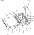
- FIG. 3 A further embodiment of a console according to the invention is shown in FIG FIG. 3 shown.
- the embodiment of the FIG. 3 realizes a number of features of the embodiment of the Figures 1 and 2 in an analogous manner, so that the above description can be applied analogously, and only differences will be discussed below.
- the carrier flanges 31 and 32 are structured. They have webs and intervening depressions.
- the transverse fields 41 and 42 are in the embodiment of FIG. 3 completely filled.
- webs 53 and 54 are arranged, which adjoin the crossing region of the rods 35, 36, 37, 38, and which have a smaller material thickness than the rods 35, 36, 37, 38.
- passages 45 and 46 are also arranged.
- the web 53 lies between the passage 45 and the crossing region and the web 54 between the passage 46 and the crossing region.
- the web 53 is smaller in area than the adjacent passage 45 and the web 54 is smaller in area than the adjacent passage 46.
- the wall part 1 and the facade part 2 at their respective plate member 11 and 21 each have a rib structure 18 and 28, respectively, on which the bridge part 3 is connected to the wall part 1 and the facade part 2.
- the wall part 1 has in its mounting plate 19 a hole for performing an anchor bolt for anchoring to the building wall.
- the facade part 2 of FIG. 3 has a retaining clip 70, which is arranged on the plate element 21 of the facade part 2. Between retaining clip 70 and plate member 21 may be in FIG. 3 only roughly schematically and fragmentarily illustrated support section 101 of the support profile construction of the facade during assembly provisionally be held by clamping.
- passage openings for the final screwing of the provisionally clamped support section 101 are provided with the facade part 2.
Landscapes
- Engineering & Computer Science (AREA)
- Architecture (AREA)
- Civil Engineering (AREA)
- Structural Engineering (AREA)
- Physics & Mathematics (AREA)
- Electromagnetism (AREA)
- Acoustics & Sound (AREA)
- Finishing Walls (AREA)
Description
- Die Erfindung betrifft eine Konsole zum Verbinden einer Fassade mit einer Gebäudewand gemäss dem Oberbegriff des Anspruchs 1. Eine solche Konsole ist ausgestattet mit einem metallischen Wandteil zur Montage an der Gebäudewand, einem metallischen Fassadenteil zur Verbindung mit der Fassade, und einem Brückenteil, welches das Fassadenteil mit dem Wandteil verbindet, wobei das Brückenteil ein Kunststoffmaterial aufweist und eine Wärmesperre zwischen dem Wandteil und dem Fassadenteil bildet.
- Eine gattungsgemässe Konsole ist aus der
EP2180115A1 bekannt. Bei einer solchen Konsole ist ein Brückenteil vorgesehen, welches eine Wärmesperre bildet, und somit einem unerwünschten Wärmeabfluss von der Wand hinweg über die Konsole entgegenwirkt. Eine weitere Konsole mit Wärmesperre ist aus derDE202004008376U bekannt. - Die
DE 102007021431 A1 beschreibt ein System zur Anbringung von Dämmmaterialien an Aussenwänden von Bauwerken, mit einem Tragwerk, das einen Dämmraum zur Aufnahme des Dämmmaterials abgrenzt und eine Aussenverkleidung tragen kann. Dabei sind mehrere singuläre Träger vorgesehen. Diese Träger springen von dem Bauwerk vor, durchqueren den Dämmraum, sind an ihren vom Bauwerk abgewandten Enden zur Anbringung der Aussenverkleidung ausgebildet und haben voneinander seitlichen und vertikalen Abstand. Die Träger können beispielsweise aus einem Kunststoffschaum hergestellt werden, wobei Einhängeelement aus Blech durch Umspritzen in den Trägern festgelegt werden können. - Die
EP 2354368 A2 beschreibt einen Befestigungsbügel für Wandisolierungen, mit einer endseitigen, vertikalen, an eine Gebäudewand anlegbaren Halteplatte, einer sich quer dazu erstreckenden, ebenfalls vertikal ausgerichteten Tragplatte und einer horizontal ausgerichteten Stützplatte, welche oben auf der Tragplatte vorgesehen ist, wobei die Halteplatte, die Tragplatte und die Stützplatte aus Kunststoff bestehen und materialeinheitlich miteinander verbunden sind. - Aus der
EP 1084816 A2 geht ein Verfahren zur Herstellung eines Verbundbauteiles aus einem mit einer Verrippung versehenen Grundkörper aus Kunststoff, der partiell oder vollständig mit einem Verstärkungselement aus Metall oder verstärktem Kunststoff verbunden wird, hervor. - Die
GB 2398580 A1 - Aufgabe der Erfindung ist es, eine Konsole anzugeben, welche besonders günstig in der Herstellung und dabei besonders zuverlässig in der Installation und Anwendung ist, und die zugleich besonders gute mechanische und thermische Eigenschaften aufweist.
- Die Aufgabe wird erfindungsgemäss durch eine Konsole mit den Merkmalen des Anspruchs 1 gelöst. Bevorzugte Ausführungsformen sind in den abhängigen Ansprüchen angegeben.
- Eine erfindungsgemässe Konsole ist dadurch gekennzeichnet, dass das Brückenteil ein Spritzgussteil aus faserverstärktem Kunststoff ist, und dass das Wandteil und das Fassadenteil vom Brückenteil zumindest bereichsweise, vorzugsweise nur bereichsweise, umspritzt sind.
- Ein erster Grundgedanke der Erfindung kann darin gesehen werden, dass das Brückenteil eine Umspritzung des Wandteils und des Fassadenteils ist. Das Brückenteil wird also in einem Umspritzverfahren mit dem Wandteil und dem Fassadenteil verbunden, das heisst das Material des Brückenteils wird bei der Fertigung im schmelzflüssigen Zustand mit dem Wandteil und dem Fassadenteil in Kontakt gebracht, und das Brückenteil härtet im Kontakt mit dem Wandteil und dem Fassadenteil aus. Dadurch, dass erfindungsgemäss eine Umspritzung als Brückenteil vorgesehen ist, kann ein besonders guter mechanischer Verbund in der Konsole erzielt werden, der insbesondere auch im Hinblick auf die Kräfte und die Temperaturänderungen im Fassadenbereich besonders zuverlässig ist.
- Nach der Erfindung bildet das Brückenteil eine Wärmesperre, also einen thermischen Isolator. Insbesondere weist das Material des Brückenteils eine geringere Wärmeleitfähigkeit als das Material des Wandteils und als das Material des Fassadenteils auf. Das Brückenteil verbindet das Fassadenteil mit dem Wandteil und das Fassadenteil wird durch das Brückenteil mechanisch am Wandteil fixiert. Vorzugsweise ist das Fassadenteil, insbesondere bei demontierter Fassade, ausschliesslich über das Brückenteil mit dem Wandteil verbunden. Hierdurch können parallele Wärmeströme vermieden und eine noch bessere thermische Isolierung realisiert werden. Das Fassadenteil und/oder das Wandteil sind vorzugsweise in unmittelbarer Weise mit dem Brückenteil verbunden, was die Herstellung weiter vereinfachen kann.
- Weiter sieht die Erfindung vor, dass das Brückenteil aus einem faserverstärkten Kunststoff besteht. Ein solcher Kunststoff hat, wie weiter unten im Detail erläutert wird, häufig thermische und mechanische Eigenschaften, die ihn für eine Anwendung in einer Konsole besonders geeignet machen.
- Bei der Fassade kann es sich vorzugsweise um eine hinterlüftete Außenwandbekleidung handeln, insbesondere gemäss DIN 18516-1, d.h. die Konsole kommt zweckmässigerweise dort zur Anwendung, wo eine Fassade einer geschlossenen Aussenwand vormontiert wird. Insbesondere kann die Erfindung in Kombination mit einer Dämmstoffschicht verwendet werden, die von der Konsole durchdrungen wird, wobei das Brückenteil zweckmässigerweise in die Dämmstoffschicht eingebettet ist. Die Fassade weist geeigneterweise eine Vielzahl von Fassadenplatten auf. Die Fassadenplatten werden vorzugsweise über eine Tragprofilkonstruktion, welche insbesondere aus Metall bestehen kann, mit den erfindungsgemässen Konsolen, insbesondere mit deren Fassadenteilen verbunden. Sofern eine Tragprofilkonstruktion vorhanden ist, kann diese nach der Erfindung als Bestandteil der Fassade angesehen werden. Geeigneterweise weist das Fassadenteil der erfindungsgemässen Konsole Mittel zum Halten eines Tragprofils auf, beispielsweise eine Klemme.
- Besonders bevorzugt ist es, dass das Brückenteil zwei beabstandete Trägerflansche aufweist, welche das Fassadenteil und das Wandteil verbinden. Hiermit können die auftretenden Kräfte, insbesondere die Windkräfte, besonders gut aufgenommen werden. Zweckmässigerweise sind das Wandteil und das Fassadenteil von den beiden Trägerflanschen des Brückenteils bereichsweise umspritzt, vorzugsweise ausschliesslich von den beiden Trägerflanschen. Hierdurch kann eine besonders kompakte Bauform erhalten werden. Die beiden Trägerflansche verlaufen vorzugsweise parallel zueinander und/oder horizontal.
- Weiterhin ist es vorteilhaft, dass das Brückenteil vier kreuzförmig, insbesondere schrägkreuzförmig, angeordnete Stäbe aufweist, über welche die beiden Trägerflansche miteinander verbunden sind. Der Kreuzungsbereich der vier Stäbe, also der Bereich, wo die vier Stäbe zusammenlaufen, liegt vorzugsweise zwischen den beiden Trägerflanschen, insbesondere mittig zwischen den beiden Trägerflanschen. Insbesondere kann sich der Anspritzpunkt des als Spritzgussteil ausgebildeten Brückenteils am Kreuzungsbereich der Stäbe befinden. Die besagten Stäbe können die beiden Trägerflansche besonders einfach und zuverlässig aussteifen, so dass insbesondere die Gewichtskraft der Fassade besonders zuverlässig aufgenommen werden kann. Darüber hinaus kann es zu einer besonders vorteilhaften Wechselwirkung zwischen der Kreuzform der Stäbe und der Verwendung eines faserverstärkten Kunststoffs in einem Spritzgussverfahren kommen. Denn die schrägkreuzförmige, das heisst X-förmige Gestaltung des Brückenteils kann eine besondere Faserorientierung bewirken. Insbesondere können die Fasern so orientiert sein, dass die Vorzugsrichtung der Fasern in den Stäben parallel zum jeweiligen Stab liegt. Damit sind die Fasern überwiegend diagonal und insbesondere in Richtung des Hauptkraftflusses bei Belastung mit Windkräften und/oder Gewichtskräften orientiert.
- Erfindungsgemäss können die vier Stäbe vier Felder einschliessen, nämlich insbesondere zwei Querfelder, welche sich zu den Trägerflanschen hin öffnen, und zwei gegenüberliegende Längsfelder, welche sich zum Wandteil beziehungsweise zum Fassadenteil hin öffnen. Die Querfelder weisen geeigneterweise einen kleineren Öffnungswinkel auf als die Längsfelder.
- Besonders bevorzugt ist es, dass das Brückenteil in zumindest einem der Längsfelder, vorzugsweise in beiden Längsfeldern, zumindest bereichsweise, vorzugsweise überall, eine geringere Materialstärke aufweist als an den Stäben. Alternativ oder zusätzlich ist es vorteilhaft, dass das Brückenteil in zumindest einem der Querfelder, vorzugsweise in beiden Querfeldern, zumindest bereichsweise, vorzugsweise überall, eine geringere Materialstärke aufweist als an den Stäben. Diese Ausführungsformen berücksichtigen, dass die auftretenden Kräfte im Wesentlichen bereits von den Verbindungsflanschen und den Stäben aufgenommen werden können, so dass die zwischen den Stäben liegenden Felder ohne wesentliche mechanische Einbussen relativ schwach ausgebildet werden können. Indem nun in den Feldern nur eine vergleichsweise geringe Materialstärke vorgesehen wird, kann die thermische Isolationseigenschaft des Brückenteils ohne wesentliche mechanische Einbussen weiter verbessert werden. Erfindungsgemäss wird unter der Materialstärke die Stärke in einer Richtung verstanden, die senkrecht zu den Feldern und/oder senkrecht zur Kreuzform der Stäbe steht. Bei einer bestimmungsgemäss montierten Konsole kann diese Richtung bevorzugt eine Horizontalrichtung sein. Die vier Stäbe weisen bevorzugt eine konstante Materialstärke und/oder alle denselben Materialstärkeverlauf auf.
- Insbesondere kann die Materialstärke in zumindest einem der Längsfelder, vorzugsweise in beiden Längsfeldern, zumindest bereichsweise gleich null sein. Besonders bevorzugt ist es daher, dass zumindest eines der beiden Längsfelder zumindest einen Durchgang aufweist. Zweckmässigerweise weisen beide Längsfelder jeweils zumindest einen Durchgang auf. Diese Durchgänge können zum Beispiel Luftpolster bilden, welche die Wärmeleitung des Brückenteils noch weiter verringern können. Unter einem Durchgang kann insbesondere eine Ausnehmung verstanden werden, die das Brückenteil senkrecht zu den Feldern und/oder senkrecht zur Kreuzform der Stäbe durchdringt.
- Weiterhin ist es vorteilhaft, dass zumindest eines der Querfelder, vorzugsweise vollständig, geschlossen ist, dass es also zweckmässigerweise keinen Durchgang aufweist. Insbesondere können beide Querfelder, vorzugsweise vollständig, geschlossen sein. Dies kann im Hinblick auf die mechanische Stabilität vorteilhaft sein. Auch kann mit dieser Ausgestaltung unter Umständen die Bildung von Bindenähten im Bereich der Verbindungsflansche verhindert oder zumindest reduziert werden. Vorzugsweise ist bei den Querfeldern ein grösserer Prozentsatz der Fläche geschlossen als bei den Längsfeldern.
- Ferner ist es bevorzugt, dass das Wandteil ein Plattenelement mit zwei gegenüberliegenden Flachseiten und zwei gegenüberliegenden Längsseiten aufweist, und/oder dass das Fassadenteil ein Plattenelement mit zwei gegenüberliegenden Flachseiten und zwei gegenüberliegenden Längsseiten aufweist, welches vorzugsweise komplanar zum Plattenelement des Wandteils verläuft. Dies kann im Hinblick auf den Fertigungsaufwand vorteilhaft sein. Insbesondere können das Wandteil und/oder das Fassadenteil als Stranggussteil ausgebildet sein. Das Wandteil kann beispielsweise eine Montageplatte zur Auflage auf der Wand aufweisen, von welcher das Plattenelement des Wandteils winklig, insbesondere rechtwinklig vorsteht. Das Fassadenteil kann eine Halteklammer aufweisen, welche vom Plattenelement des Fassadenteils vorsteht, wobei zwischen der Halteklammer und dem Plattenelement des Fassadenteils ein Tragprofil der Tragprofilkonstruktion der Fassade verklemmbar ist. Vorzugsweise ist eine Stirnseite des Fassadenteils einer Stirnseite des Wandteils zugewandt.
- Bei bestimmungsgemäss montierter Konsole verlaufen die Stäbe und die beiden Platten zweckmässigerweise in zumindest einer vertikal verlaufenden Ebene, vorzugsweise in genau einer vertikal verlaufenden Ebene.
- Insbesondere kann vorgesehen sein, dass die gegenüberliegenden Längsseiten des Wandteils und/oder die gegenüberliegenden Längsseiten des Fassadenteils bereichsweise vom Brückenteil umschlossen sind, wobei das Brückenteil vorzugsweise einen Passsitz für die gegenüberliegenden Längsseiten des Wandteils beziehungsweise die gegenüberliegenden Längsseiten des Fassadenteils bildet. Durch einen längsseitigen Passsitz können die Gewichtskräfte der Fassade besonders gut übertragen werden.
- Erfindungsgemäss weist der faserverstärkte Kunststoff eine Matrix und eine Vielzahl von Fasern auf. Bei der Matrix kann es sich insbesondere um einen Thermoplast handeln, beispielsweise um ein Polyamid, vorzugsweise um Polyamid 6.6.
- Eine weitere bevorzugte Ausgestaltung der Erfindung liegt darin, dass die Wärmeausdehnungszahl der Matrix grösser und die Wärmeausdehnungszahl der Fasern kleiner ist als die Wärmeausdehnungszahl der beiden Plattenelemente. Hier kann es wieder zu einer vorteilhaften Wechselwirkung mit der erfindungsgemässen Geometrie kommen: denn da die Vorzugsrichtung der Fasern in den Stäben vorteilhafterweise parallel zum jeweiligen Stab verläuft, wird die thermische Ausdehnungszahl der Stäbe längs der Stäbe gesehen zwischen der thermische Ausdehnungszahl der Fasern und der thermischen Ausdehnungszahl der Kunststoffmatrix liegen. In der besagten bevorzugten Ausgestaltung kann somit die thermische Ausdehnung des Brückenteils an die thermische Ausdehnung des benachbarten metallischen Wandteils und/oder des benachbarten metallischen Fassadenteils angeglichen werden, so dass eine unerwünschte thermische Spannung am Übergang Brückenteil/Wandteil beziehungsweise am Übergang Brückenteil/Fassadenteil vermieden werden kann. Durch die Faserorientierung entlang der Diagonalen kann die thermische Ausdehnung des Kunststoffs an die thermische Ausdehnung des benachbarten Metalls angenähert werden.
- Zweckmässigerweise kann vorgesehen sein, dass die vier Stäbe, vorzugsweise die vier Stäbe und die beiden Trägerflansche, besonders bevorzugt das gesamte Brückenteil, spiegelsymmetrisch zu einer, vorzugsweise zu zwei Symmetrieebenen, sind beziehungsweise ist. Eine Symmetrieebene kann insbesondere senkrecht zur Kreuzform der Stäbe stehen und durch das Wandteil und das Fassadenteil hindurch verlaufen. Diese Symmetrieebene liegt bei bestimmungsgemäss montierter Konsole vorzugsweise in der Horizontalen. Eine symmetrische Ausgestaltung kann im Hinblick auf die mechanischen Eigenschaften und/oder die Faserorientierung vorteilhaft sein. Insbesondere kann es die symmetrische Ausgestaltung ermöglichen, die Konsole bei gleichen Lastwerten in mehreren Orientierungen zu installieren, so dass auch die Anwendung vereinfacht ist.
- Eine andere vorteilhafte Weiterbildung der Erfindung liegt darin, dass ein Anspritzpunkt des Brückenteils in zumindest einer Symmetrieebene des Brückenteils liegt. Hierdurch können die Faserorientierung und/oder die mechanischen Eigenschaften weiter verbessert werden.
- Besonders bevorzugt ist es, dass das Brückenteil genau einen Anspritzpunkt aufweist, was die Herstellung vereinfachen kann.
- Vorzugsweise kann vorgesehen sein, dass ein Anspritzpunkt des Brückenteils in einem Kreuzungsbereich der vier Stäbe liegt, also insbesondere mittig in den Diagonalen. Durch die erfindungsgemässe Geometrie und die Wahl eines Anspritzpunktes in einer Symmetrieebene und/oder im Kreuzungsbereich der Stäbe können die Fasern im Brückenteil gezielt orientiert werden und dadurch folgendes erreicht werden:
- a) Die Wärmeausdehnung des Kunststoffformteils nähert sich der Wärmeausdehnung der berührenden Metallteile an. Dadurch werden mechanische Spannungen im Bauteil bei Temperaturwechseln minimiert.
- b) Der Hauptkraftfluss verläuft in Faserrichtung und somit wird die höhere Materialfestigkeit in Faserrichtung genutzt.
- Vorzugsweise weist das Wandteil und/oder das Fassadenteil jeweils eine Rippenstruktur auf, welche vom Brückenteil umspritzt ist. Hierdurch kann eine noch bessere Kräfteübertragung zwischen den einzelnen Teilen erreicht werden. Die Rippenstruktur kann insbesondere am Plattenelement des Wandteils beziehungsweise des Fassadenteils vorgesehen sein. Jede Rippenstruktur weist geeigneterweise eine Vielzahl von Rippen auf, die sich an zumindest einer Flachseite, vorzugsweise an beiden Flachseiten, des jeweiligen Plattenelements erstrecken und/oder die parallel zu Stirnseite des jeweiligen Plattenelements verlaufen.
- Weiterhin ist es bevorzugt, dass das Brückenteil einstückig ausgebildet ist. Hierdurch kann der Herstellungsaufwand gesenkt und die mechanische Stabilität noch weiter verbessert werden. Insbesondere können die Stäbe und die Verbindungsflansche einstückig ausgebildet sein.
- Die Erfindung wird nachfolgend anhand bevorzugter Ausführungsbeispiele näher erläutert, die schematisch in den beiliegenden Figuren dargestellt sind, wobei einzelne Merkmale der nachfolgend gezeigten Ausführungsbeispiele im Zusammenhang mit der Erfindung einzeln oder in beliebiger Kombination realisiert werden können. In den Figuren zeigen schematisch:
- Figur 1:
- eine erste Ausführungsform einer erfindungsgemässen Konsole in perspektivischer Darstellung;
- Figur 2:
- eine Detailansicht der Konsole gemäss
Figur 1 von der Seite, und - Figur 3:
- eine zweite Ausführungsform einer erfindungsgemässen Konsole in perspektivischer Darstellung.
- Gleich wirkende Elemente sind in den Figuren mit denselben Bezugszeichen gekennzeichnet.
- Ein erstes Ausführungsbeispiel einer erfindungsgemässen Konsole ist in den
Figuren 1 und 2 dargestellt. Die Konsole weist ein Wandteil 1, welches an einer Gebäudewand 100 montiert ist, ein Fassadenteil 2, welches an einer nicht dargestellten Fassade montiert ist, sowie ein Brückenteil 3 auf, welches das Fassadenteil 2 mechanisch am Wandteil 1 hält und dabei eine Wärmesperre zwischen Wandteil 1 und Fassadenteil 2 bildet. - Das Wandteil 1 weist eine Montageplatte 19, die plan auf der Gebäudewand 100 aufliegt, und ein Plattenelement 11 auf, welches rechtwinklig von der Montageplatte 19 vorsteht, und an welchem das Brückenteil 3 angeordnet ist. Das Fassadenteil 2 weist ebenfalls ein Plattenelement 21 auf. Das Plattenelement 21 des Fassadenteils 2 wird vom Brückenteil 3 getragen. Dabei verläuft das Plattenelement 21 des Fassadenteils 2 parallel und in der dargestellten Ausführungsform komplanar zum Plattenelement 11 des Wandteils 1.
- Das Plattenelement 11 des Wandteils 1 weist zwei gegenüberliegende Flachseiten 12 und 13, zwei gegenüberliegende schmale Längsseiten 14 und 15 und eine schmale, freie Stirnseite 16 auf. Das Plattenelement 21 des Fassadenteils 2 weist ebenfalls zwei gegenüberliegende Flachseiten 22 und 23, zwei gegenüberliegende schmale Längsseiten 24 und 25 und eine schmale, freie Stirnseite 26 auf. Die freie Stirnseite 26 des Fassadenteils 2 und die freie Stirnseite 16 des Wandteils 1 sind einander und dem Brückenteil 3 zugewandt.
- Bei der bestimmungsgemässen Montage verlaufen die Flachseiten 12, 13, 22 und 23 und/oder die Stirnseiten 16 und 26 in der Regel vertikal, d.h. die Längsseiten 14 und 24 liegen oberhalb der Längsseiten 15 beziehungsweise 25. Grundsätzlich ist aber auch eine Montage möglich, bei der die Flachseiten 12, 13, 22 und 23 horizontal oder schräg verlaufen.
- Das Brückenteil 3 ist ein Spritzgussteil aus faserverstärktem Kunststoff. Es weist einen ersten, vorzugsweise oberen Trägerflansch 31 und einen zweiten, vorzugsweise unteren Trägerflansch 32 auf. Die beiden Trägerflansche 31, 32 verlaufen beabstandet voneinander, vorzugsweise in horizontaler Richtung, jeweils vom Wandteil 1 zum Fassadenteil 2, und verbinden das Fassadenteil 2 mit dem Wandteil 1. Dabei sind das Wandteil 1 und das Fassadenteil 2 von den beiden Trägerflanschen 31 und 32 des Brückenteils 3 umspritzt. Jeder der beiden Trägerflansche 31 und 32 ist in Kontakt mit den beiden Flachseiten 12 und 13 des Wandteils 1 und mit den beiden Flachseiten 22 und 23 des Fassadenteils 2. Vorzugsweise kann der erste Trägerflansch 31 darüber hinaus in Kontakt mit der Längsseite 14 des Wandteils 1 und der Längsseite 24 des Fassadenteils 2 und/oder der zweite Trägerflansch 32 in Kontakt mit der Längsseite 15 des Wandteils 1 und der Längsseite 25 des Fassadenteils 2 sein.
- Das Brückenteil 3 weist ferner vier Stäbe 35, 36, 37, 38 auf, über welche die beiden Trägerflansche 31 und 32 miteinander verbunden sind, und welche die beiden Trägerflansche 31 und 32 gegeneinander aussteifen. Die vier Stäbe 35, 36, 37, 38 bilden eine Kreuzform und verlaufen in einer parallel, insbesondere komplanar, zu den Plattenelementen 11 und/oder 21 verlaufenden Ebene, wobei der Kreuzungsbereich der vier Stäbe 35, 36, 37, 38, also der Bereich, in dem die vier Stäbe 35, 36, 37, 38 zusammenlaufen, mittig zwischen den beiden Trägerflanschen 31 und 32 liegt. Die vier Stäbe 35, 36, 37, 38 und die beiden Trägerflansche 31 und 32 sind spiegelsymmetrisch zu einer Ebene ausgebildet, die senkrecht zur Kreuzform der vier Stäbe 35, 36, 37, 38 steht, und die zwischen den beiden Trägerflanschen 31 und 32 verläuft (in
Fig. 2 steht diese Symmetrieebene senkrecht zur Bildebene und verläuft von links nach rechts). Die vier Stäbe 35, 36, 37, 38 und die beiden Trägerflansche 31 und 32 sind weiterhin spiegelsymmetrisch zu einer weiteren Symmetrieebene ausgebildet, die senkrecht zur Kreuzform der vier Stäbe 35, 36, 37, 38 steht, und die die beiden Trägerflanschen 31 und 32 schneidet (inFig. 2 steht diese zweite Symmetrieebene senkrecht zur Bildebene und verläuft von oben nach unten). - Der Anspritzpunkt 40 des Brückenteils, also der Bereich, an dem das faserverstärkte Kunststoffmaterial beim Spritzgiessen in das Spritzgusswerkzeug zugeführt wurde, liegt im Kreuzungsbereich der vier Stäbe 35, 36, 37, 38. In den vier Stäben 35, 36, 37, 38 liegt die Vorzugsrichtung der Fasern des faserverstärkten Kunststoffmaterials wie in
Figur 2 durch Pfeile angedeutet zumindest annähernd parallel zum jeweiligen Stab. - Die vier Stäbe 35, 36, 37, 38 schliessen in der Ebene ihrer Kreuzform vier Felder 41, 42, 43, 44 ein, nämlich zwei diametral gegenüberliegende Querfelder 41 und 42, welche sich ausgehend vom Kreuzungsbereich der Stäbe 35, 36, 37, 38 zum Trägerflansch 31 beziehungsweise zum Trägerflansch 32 hin öffnen, und zwei diametral gegenüberliegende Längsfelder 43 und 44, welche sich ausgehend vom Kreuzungsbereich der Stäbe 35, 36, 37, 38 zum Wandteil 1 beziehungsweise zum Fassadenteil 2 hin öffnen. Die Querfelder 41 und 42 weisen einen kleineren Öffnungswinkel auf als die Längsfelder 43 und 44.
- Im dargestellten Ausführungsbeispiel sind die Felder 41, 42, 43, 44 nicht mit Kunststoffmaterial gefüllt und bilden jeweils einen Durchgang. Die Felder 41, 42, 43 und/oder 44 können jedoch auch mit Kunststoffmaterial gefüllt sein. Für die Materialstärken gilt dann bevorzugt:

- a die Materialstärke im jeweiligen Längsfeld 43 und/oder 44,
- b die Materialstärke im jeweiligen Querfelder 41 und/oder 42, und
- c die Materialstärke in zumindest einem der Stäbe 35, 36, 37, 38, vorzugsweise in allen Stäben ist.
- Dieser Zusammenhang ist nicht auf das Ausführungsbeispiel der
Figuren 1 und 2 beschränkt, sondern kann auch bei anderen erfindungsgemässen Geometrien zum Einsatz kommen. - Die in den
Figuren 1 und 2 gezeigte Konsole kann insbesondere die Kraft F1, beispielsweise eine Windkraft an der Fassade, und die Kraft F2, beispielsweise eine Gewichtskraft der Fassade, aufnehmen. - Eine weitere Ausführungsform einer erfindungsgemässen Konsole ist in
Figur 3 dargestellt. Die Ausführungsform derFigur 3 realisiert eine Reihe von Merkmalen der Ausführungsform derFiguren 1 und 2 in analoger Weise, so dass die obenstehende Beschreibung analog angewandt werden kann, und im Folgenden nur auf Unterschiede eingegangen wird. - Beim Ausführungsbeispiel der
Figur 3 sind die Trägerflansche 31 und 32 strukturiert ausgeführt. Sie weisen Stege und dazwischenliegende Vertiefungen auf. - Die Querfelder 41 und 42 sind beim Ausführungsbeispiel der
Figur 3 vollständig gefüllt. In den Längsfeldern 43 und 44 sind Stege 53 beziehungsweise 54 angeordnet, welche an den Kreuzungsbereich der Stäbe 35, 36, 37, 38 angrenzen, und welche eine geringere Materialstärke aufweisen als die Stäbe 35, 36, 37, 38. In den Längsfeldern 43 und 44 sind darüber hinaus Durchgänge 45 und 46 angeordnet. Der Steg 53 liegt dabei zwischen dem Durchgang 45 und dem Kreuzungsbereich und der Steg 54 zwischen dem Durchgang 46 und dem Kreuzungsbereich. Der Steg 53 ist flächenkleiner als der benachbarte Durchgang 45 und der Steg 54 ist flächenkleiner als der benachbarte Durchgang 46. - Beim Ausführungsbeispiel der
Figur 3 weisen das Wandteil 1 und das Fassadenteil 2 an ihrem jeweiligen Plattenelement 11 beziehungsweise 21 jeweils eine Rippenstruktur 18 beziehungsweise 28 auf, an der das Brückenteil 3 mit dem Wandteil 1 beziehungsweise dem Fassadenteil 2 verbunden ist. Das Wandteil 1 weist in seiner Montageplatte 19 ein Loch zum Durchführen eines Ankerbolzens für eine Verankerung an der Gebäudewand auf. Das Fassadenteil 2 derFigur 3 weist eine Halteklammer 70 auf, die am Plattenelement 21 des Fassadenteils 2 angeordnet ist. Zwischen Halteklammer 70 und Plattenelement 21 kann ein inFigur 3 lediglich grob schematisch und ausschnittsweise dargestelltes Tragprofil 101 der Tragprofilkonstruktion der Fassade bei der Montage vorläufig durch Klemmung gehalten werden. Im Plattenelement 21 des Fassadenteils 2 sind Durchgangsöffnungen zum endgültigen Verschrauben des vorläufig geklemmten Tragprofils 101 mit dem Fassadenteil 2 vorgesehen.
Claims (11)
- Konsole zum Verbinden einer Fassade mit einer Gebäudewand (100), mit einem metallischen Wandteil (1) zur Montage an der Gebäudewand (100), einem metallischen Fassadenteil (2) zur Verbindung mit der Fassade, und einem Brückenteil (3), welches das Fassadenteil (2) mit dem Wandteil (1) verbindet, wobei das Brückenteil (3) ein Kunststoffmaterial aufweist und eine Wärmesperre zwischen dem Wandteil (1) und dem Fassadenteil (2) bildet,
dadurch gekennzeichnet,
dass das Brückenteil (3) ein Spritzgussteil aus faserverstärktem Kunststoff ist, und dass das Wandteil (1) und das Fassadenteil (2) vom Brückenteil (3) zumindest bereichsweise umspritzt sind. - Konsole nach Anspruch 1,
dadurch gekennzeichnet,
dass das Brückenteil (3) zwei beabstandete Trägerflansche (31, 32) aufweist, welche das Fassadenteil (2) und das Wandteil (1) verbinden, und
dass das Wandteil (1) und das Fassadenteil (2) von den beiden Trägerflanschen (31, 32) des Brückenteils (3) bereichsweise umspritzt sind. - Konsole nach Anspruch 2,
dadurch gekennzeichnet,
dass das Brückenteil (3) ferner vier kreuzförmig, insbesondere schrägkreuzförmig, angeordnete Stäbe (35, 36, 37, 38) aufweist, über welche die beiden Trägerflansche (31, 32) miteinander verbunden sind. - Konsole nach Anspruch 3,
dadurch gekennzeichnet,
dass die vier Stäbe (35, 36, 37, 38) vier Felder (41, 42, 43, 44) einschliessen, nämlich zwei Querfelder (41, 42), welche sich zu den Trägerflanschen (31, 32) hin öffnen, und zwei Längsfelder (43, 44), welche sich zum Wandteil (1) beziehungsweise zum Fassadenteil (2) hin öffnen,
wobei das Brückenteil (3) in den Längsfeldern (43, 44) eine geringere Materialstärke aufweist als an den Stäben (35, 36, 37, 38), und/oder
wobei das Brückenteil (3) in den Querfeldern (41, 42) eine geringere Materialstärke aufweist als an den Stäben (35, 36, 37, 38). - Konsole nach Anspruch 4,
dadurch gekennzeichnet,
dass die Längsfelder (43, 44) jeweils zumindest einen Durchgang (45, 46) aufweisen, und
dass die Querfelder (41, 42), vorzugsweise vollständig, geschlossen sind. - Konsole nach einem der Ansprüche 3 bis 5,
dadurch gekennzeichnet,
dass die Hauptfaserorientierung des faserverstärkten Kunststoffs in den Stäben (35, 36, 37, 38) zumindest annähernd parallel zum jeweiligen Stab (35, 36, 37, 38) verläuft. - Konsole nach einem der vorstehenden Ansprüche,
dadurch gekennzeichnet,
dass das Wandteil (1) ein Plattenelement (11) mit zwei gegenüberliegenden Flachseiten (12, 13) und zwei gegenüberliegenden Längsseiten (14, 15) aufweist, und dass das Fassadenteil (2) ein Plattenelement (21) mit zwei gegenüberliegenden Flachseiten (22, 23) und zwei gegenüberliegenden Längsseiten (24, 25) aufweist, welches vorzugsweise komplanar zum Plattenelement (11) des Wandteils (1) verläuft, wobei die gegenüberliegenden Längsseiten (14, 15) des Wandteils (1) und/oder die gegenüberliegenden Längsseiten (24, 25) des Fassadenteils (2) bereichsweise vom Brückenteil (3) umschlossen sind, wobei das Brückenteil (3) vorzugsweise einen Passsitz für die gegenüberliegenden Längsseiten (14, 15) des Wandteils (1) und/oder die gegenüberliegenden Längsseiten (24, 25) des Fassadenteils (2) bildet. - Konsole nach Anspruch 7,
dadurch gekennzeichnet,
dass der faserverstärkte Kunststoff eine Matrix und eine Vielzahl von Fasern aufweist, wobei die Wärmeausdehnungszahl der Matrix grösser und die Wärmeausdehnungszahl der Fasern kleiner ist als die Wärmeausdehnungszahl der beiden Plattenelemente (11, 21). - Konsole nach Anspruch einem der Ansprüche 3 bis 6,
dadurch gekennzeichnet,
dass ein Anspritzpunkt (40) des Brückenteils (3) in einem Kreuzungsbereich der vier Stäbe (35, 36, 37, 38) liegt. - Konsole nach einem der vorstehenden Ansprüche,
dadurch gekennzeichnet,
dass das Wandteil (1) und das Fassadenteil (2) jeweils eine Rippenstruktur (18 beziehungsweise 28) aufweist, welche vom Brückenteil (3) umspritzt ist. - Konsole nach einem der vorstehenden Ansprüche,
dadurch gekennzeichnet,
dass das Brückenteil (3) einstückig ausgebildet ist.
Priority Applications (1)
| Application Number | Priority Date | Filing Date | Title |
|---|---|---|---|
| PL14700078T PL2943624T3 (pl) | 2013-01-09 | 2014-01-07 | Wspornik termoizolacyjny do łączenia elewacji ze ścianą budynku |
Applications Claiming Priority (2)
| Application Number | Priority Date | Filing Date | Title |
|---|---|---|---|
| DE102013200211.4A DE102013200211A1 (de) | 2013-01-09 | 2013-01-09 | Konsole |
| PCT/EP2014/050112 WO2014108378A1 (de) | 2013-01-09 | 2014-01-07 | Wärmeisolierende konsole zum verbinden einer fassade mit einer gebäudewand |
Publications (2)
| Publication Number | Publication Date |
|---|---|
| EP2943624A1 EP2943624A1 (de) | 2015-11-18 |
| EP2943624B1 true EP2943624B1 (de) | 2019-05-15 |
Family
ID=49943371
Family Applications (1)
| Application Number | Title | Priority Date | Filing Date |
|---|---|---|---|
| EP14700078.0A Active EP2943624B1 (de) | 2013-01-09 | 2014-01-07 | Wärmeisolierende konsole zum verbinden einer fassade mit einer gebäudewand |
Country Status (7)
| Country | Link |
|---|---|
| US (1) | US10119267B2 (de) |
| EP (1) | EP2943624B1 (de) |
| CA (1) | CA2896974C (de) |
| DE (1) | DE102013200211A1 (de) |
| PL (1) | PL2943624T3 (de) |
| RU (1) | RU2604243C1 (de) |
| WO (1) | WO2014108378A1 (de) |
Families Citing this family (16)
| Publication number | Priority date | Publication date | Assignee | Title |
|---|---|---|---|---|
| GB201303947D0 (en) * | 2013-03-05 | 2013-04-17 | Corp | Bracket |
| HUE043706T2 (hu) * | 2016-04-26 | 2019-09-30 | Halfen Gmbh | Konzolhorgony falburkolat rögzítésére egy tartófalon |
| RU170634U1 (ru) * | 2016-09-22 | 2017-05-03 | Владимир Иванович Демиденко | Термоизолирующий кронштейн для крепления профилей навесных фасадов |
| EP3333336B1 (de) * | 2016-12-09 | 2026-03-18 | Leviat GmbH | Konsolanker |
| RU174983U1 (ru) * | 2017-06-14 | 2017-11-15 | Владимир Иванович Демиденко | Термоизолирующий кронштейн для крепления профилей навесных фасадов |
| RU174989U1 (ru) * | 2017-06-14 | 2017-11-15 | Владимир Иванович Демиденко | Термоизолирующий кронштейн для крепления профилей навесных фасадов |
| RU174990U1 (ru) * | 2017-06-14 | 2017-11-15 | Владимир Иванович Демиденко | Термоизолирующий кронштейн для крепления профилей навесных фасадов |
| RU174987U1 (ru) * | 2017-06-14 | 2017-11-15 | Владимир Иванович Демиденко | Термоизолирующий кронштейн для крепления профилей навесных фасадов |
| RU174988U1 (ru) * | 2017-06-14 | 2017-11-15 | Владимир Иванович Демиденко | Термоизолирующий кронштейн для крепления профилей навесных фасадов |
| RU175375U1 (ru) * | 2017-06-14 | 2017-12-01 | Владимир Иванович Демиденко | Термоизолирующий кронштейн для крепления профилей навесных фасадов |
| RU174986U1 (ru) * | 2017-06-14 | 2017-11-15 | Владимир Иванович Демиденко | Термоизолирующий кронштейн для крепления профилей навесных фасадов |
| DE102017010843A1 (de) * | 2017-11-23 | 2019-05-23 | Wilhelm Modersohn Gmbh & Co Kg | Fassadenverankerung |
| US11371240B1 (en) * | 2020-10-13 | 2022-06-28 | Joseph J. FORAL | Insulation retainer clip |
| DE102021210867A1 (de) | 2021-09-28 | 2023-03-30 | UAB "Dona Dei" | Halter eines hinterlüfteten Fassadenrahmensystems |
| EP4400670A1 (de) * | 2023-01-13 | 2024-07-17 | James Hardie Technology Limited | Befestigungssystem |
| CH720515B1 (de) * | 2023-02-17 | 2026-03-13 | Gft Fassaden Ag | Konsole und Fassadenunterkonstruktion mit der Konsole |
Citations (1)
| Publication number | Priority date | Publication date | Assignee | Title |
|---|---|---|---|---|
| DE202004008376U1 (de) * | 2004-05-26 | 2004-09-09 | Bamberger, Claus | Fassadenhalter zur thermischen Entkopplung von Fassadenunterkonstruktionen |
Family Cites Families (21)
| Publication number | Priority date | Publication date | Assignee | Title |
|---|---|---|---|---|
| GB686238A (en) * | 1949-06-13 | 1953-01-21 | Eric Birger Fernberg | An improved method and means of fastening |
| DE3223343A1 (de) * | 1982-06-23 | 1983-12-29 | Wilfried Dipl.-Ing. 7031 Nufringen Ensinger | Verbundprofil, insbesondere fuer rahmen von fenstern, tueren und fassadenelementen |
| US6421979B1 (en) * | 1999-09-16 | 2002-07-23 | Basf Aktiengesellschaft | Composite constructional element |
| DE10154553B4 (de) * | 2001-11-07 | 2005-06-09 | Saint-Gobain Sekurit Deutschland Gmbh & Co. Kg | Verfahren und Vorrichtung zum Herstellen eines Profilstrangs an einem Bauteil |
| US6910311B2 (en) * | 2002-06-06 | 2005-06-28 | Verne Leroy Lindberg | Members with a thermal break |
| US6688680B1 (en) * | 2002-12-17 | 2004-02-10 | Bayer Polymers Llc | Molded cross vehicle beam |
| GB2398580B (en) * | 2003-02-24 | 2005-01-05 | Corus Bausysteme Gmbh | Elongate retaining element for building sheets |
| GB0327065D0 (en) * | 2003-11-20 | 2003-12-24 | Intier Automotive Interiors Lt | Apparatus and method for positioning reinforcement material within an interior trim panel |
| US20050241111A1 (en) * | 2004-04-12 | 2005-11-03 | Prokop David M | Ergonomic handle with thumb support |
| RU2307906C2 (ru) * | 2005-08-16 | 2007-10-10 | Игорь Сергеевич Бабаян | Способ монтажа вентилируемой облицовки зданий и конструкция ограждения для реализации способа |
| DE102007021431A1 (de) * | 2006-05-09 | 2007-11-15 | Böhm, Martin E. | System und Verfahren zur Anbringung von Dämmmaterialien an Bauwerken |
| US20090173029A1 (en) * | 2008-01-07 | 2009-07-09 | Dennis Albert Socha | Polymeric acoustic isolator clip for isolating wallboard channels from frame member |
| CH699778A1 (de) | 2008-10-21 | 2010-04-30 | Wagner System Ag | Verbindungsteil für Gebäudehüllenverkleidung. |
| US20100117262A1 (en) * | 2008-11-13 | 2010-05-13 | Donald Gringer | Method of dual molding products with logos and other indicia |
| RU90091U1 (ru) * | 2009-03-10 | 2009-12-27 | Владимир Васильевич Зеленский | Система фасадная с вентилируемым воздушным зазором, доборный кронштейн, стойка и кляммер, входящие в нее |
| DE102009056741A1 (de) * | 2009-12-04 | 2011-06-09 | Pröckl GmbH | Anordnung mit einer Tragkonstruktion, einem Abstandshalter und einer äußeren Fassadenschale |
| DE102010011168A1 (de) | 2010-01-29 | 2011-08-04 | Lorenz Kunststofftechnik GmbH, 49134 | Befestigungsbügel für Wandisolierungen |
| US8973334B2 (en) * | 2010-12-06 | 2015-03-10 | Scott Croasdale | System and methods for thermal isolation of components used |
| US8833025B2 (en) * | 2011-01-04 | 2014-09-16 | Advanced Architectural Products, Llc | Polymer-based bracket system for exterior cladding |
| US8939416B2 (en) * | 2012-08-29 | 2015-01-27 | Andre Duranleau | Front adjustable wall panel mounting device |
| US9121169B2 (en) * | 2013-07-03 | 2015-09-01 | Columbia Insurance Company | Veneer tie and wall anchoring systems with in-cavity ceramic and ceramic-based thermal breaks |
-
2013
- 2013-01-09 DE DE102013200211.4A patent/DE102013200211A1/de not_active Withdrawn
-
2014
- 2014-01-07 PL PL14700078T patent/PL2943624T3/pl unknown
- 2014-01-07 US US14/759,605 patent/US10119267B2/en active Active
- 2014-01-07 EP EP14700078.0A patent/EP2943624B1/de active Active
- 2014-01-07 CA CA2896974A patent/CA2896974C/en active Active
- 2014-01-07 WO PCT/EP2014/050112 patent/WO2014108378A1/de not_active Ceased
- 2014-01-07 RU RU2015133029/03A patent/RU2604243C1/ru active
Patent Citations (1)
| Publication number | Priority date | Publication date | Assignee | Title |
|---|---|---|---|---|
| DE202004008376U1 (de) * | 2004-05-26 | 2004-09-09 | Bamberger, Claus | Fassadenhalter zur thermischen Entkopplung von Fassadenunterkonstruktionen |
Also Published As
| Publication number | Publication date |
|---|---|
| RU2604243C1 (ru) | 2016-12-10 |
| CA2896974C (en) | 2017-07-11 |
| DE102013200211A1 (de) | 2014-07-10 |
| EP2943624A1 (de) | 2015-11-18 |
| WO2014108378A1 (de) | 2014-07-17 |
| US20150361651A1 (en) | 2015-12-17 |
| US10119267B2 (en) | 2018-11-06 |
| PL2943624T3 (pl) | 2019-11-29 |
| CA2896974A1 (en) | 2014-07-17 |
Similar Documents
| Publication | Publication Date | Title |
|---|---|---|
| EP2943624B1 (de) | Wärmeisolierende konsole zum verbinden einer fassade mit einer gebäudewand | |
| DE69600927T2 (de) | Kernpaneel | |
| EP2653625B1 (de) | Thermisch isolierendes Bauelement | |
| EP4036338B1 (de) | Einrichtung zur nachträglichen thermisch isolierenden, kraftübertragenden anbindung eines zweiten lastaufnehmenden bauwerksteils an ein erstes lastaufnehmendes bauwerksteil und bauwerk mit einer solchen einrichtung | |
| EP3057774B1 (de) | Bauteil mit einem befestigungsbereich für eine schraubverbindung sowie formteil und befestigungsteil | |
| DE3345592C2 (de) | ||
| EP0117897B1 (de) | Bauelement zur Wärmedämmung bei Gebäuden | |
| EP0100824B1 (de) | Verbundprofil, insbesondere für Rahmen von Fenstern, Türen und Fassadenelementen | |
| DE10102931A1 (de) | Bauelement zur Wärmedämmung | |
| EP2725159A1 (de) | Haltevorrichtung, Verfahren zum Herstellen einer Haltevorrichtung sowie Verwendung einer Haltevorrichtung an einer Vorhangwand | |
| EP2873784A1 (de) | Beabstandungsvorrichtung | |
| EP2365157B1 (de) | Verbindungseinrichtung zur Verbindung einer Wand mit einem Fassadenelement oder mit einem Fassadenelementhalter | |
| DE19543768A1 (de) | Balkonanschluß | |
| EP0109093A1 (de) | Verstärkungsvorrichtung für Kabinen, insbesondere Aufbauten auf Lastkraftwagen | |
| EP1437478B1 (de) | Wärmegedämmtes Verbundprofil | |
| EP3656547B1 (de) | Isolierpaneel, komponente eines fahrzeugaufbaus, fahrzeugaufbau, fahrzeug und herstellungsverfahren | |
| EP4212317B1 (de) | Isolierpaneel, komponente eines fahrzeugaufbaus, fahrzeugaufbau und fahrzeug | |
| EP0810334A1 (de) | Bauelement zur Wärmedämmung | |
| EP3788210B1 (de) | Querkraftanker | |
| EP1932998A1 (de) | Verbundprofil und Verfahren zur Herstellung eines Verbundprofils | |
| EP2708760B1 (de) | Dämmelement einer Wandankeranordnung | |
| EP1878840B1 (de) | Bauelement zur Wärmedämmung zwischen zwei zu betonierenden Bauteilen | |
| DE102004062800B4 (de) | Formschlussverbindung | |
| DE102016119380A1 (de) | Isolierprofil für Brandschutzsysteme | |
| DE20011987U1 (de) | Holz-Beton-Verbunddecke |
Legal Events
| Date | Code | Title | Description |
|---|---|---|---|
| PUAI | Public reference made under article 153(3) epc to a published international application that has entered the european phase |
Free format text: ORIGINAL CODE: 0009012 |
|
| 17P | Request for examination filed |
Effective date: 20150810 |
|
| AK | Designated contracting states |
Kind code of ref document: A1 Designated state(s): AL AT BE BG CH CY CZ DE DK EE ES FI FR GB GR HR HU IE IS IT LI LT LU LV MC MK MT NL NO PL PT RO RS SE SI SK SM TR |
|
| AX | Request for extension of the european patent |
Extension state: BA ME |
|
| RIN1 | Information on inventor provided before grant (corrected) |
Inventor name: HENSEL, TORSTEN Inventor name: USKE, KLAUS Inventor name: WUEST, ANDREAS Inventor name: ABBAS, SHAHBAZ Inventor name: PETZOLD, FLORIAN Inventor name: BROCKMUELLER, KAY |
|
| DAX | Request for extension of the european patent (deleted) | ||
| STAA | Information on the status of an ep patent application or granted ep patent |
Free format text: STATUS: EXAMINATION IS IN PROGRESS |
|
| 17Q | First examination report despatched |
Effective date: 20180502 |
|
| REG | Reference to a national code |
Ref country code: DE Ref legal event code: R079 Ref document number: 502014011711 Country of ref document: DE Free format text: PREVIOUS MAIN CLASS: E04F0013080000 Ipc: E04B0001410000 |
|
| GRAP | Despatch of communication of intention to grant a patent |
Free format text: ORIGINAL CODE: EPIDOSNIGR1 |
|
| STAA | Information on the status of an ep patent application or granted ep patent |
Free format text: STATUS: GRANT OF PATENT IS INTENDED |
|
| RIC1 | Information provided on ipc code assigned before grant |
Ipc: E04B 1/38 20060101ALI20190208BHEP Ipc: E04B 1/41 20060101AFI20190208BHEP Ipc: E04F 13/08 20060101ALI20190208BHEP Ipc: E04B 1/76 20060101ALI20190208BHEP |
|
| INTG | Intention to grant announced |
Effective date: 20190226 |
|
| RIN1 | Information on inventor provided before grant (corrected) |
Inventor name: HENSEL, TORSTEN Inventor name: ABBAS, SHAHBAZ Inventor name: USKE, KLAUS Inventor name: BROCKMUELLER, KAY Inventor name: PETZOLD, FLORIAN Inventor name: WUEST, ANDREAS |
|
| GRAS | Grant fee paid |
Free format text: ORIGINAL CODE: EPIDOSNIGR3 |
|
| GRAA | (expected) grant |
Free format text: ORIGINAL CODE: 0009210 |
|
| STAA | Information on the status of an ep patent application or granted ep patent |
Free format text: STATUS: THE PATENT HAS BEEN GRANTED |
|
| AK | Designated contracting states |
Kind code of ref document: B1 Designated state(s): AL AT BE BG CH CY CZ DE DK EE ES FI FR GB GR HR HU IE IS IT LI LT LU LV MC MK MT NL NO PL PT RO RS SE SI SK SM TR |
|
| REG | Reference to a national code |
Ref country code: CH Ref legal event code: EP |
|
| REG | Reference to a national code |
Ref country code: DE Ref legal event code: R096 Ref document number: 502014011711 Country of ref document: DE |
|
| REG | Reference to a national code |
Ref country code: IE Ref legal event code: FG4D Free format text: LANGUAGE OF EP DOCUMENT: GERMAN |
|
| REG | Reference to a national code |
Ref country code: SK Ref legal event code: T3 Ref document number: E 31322 Country of ref document: SK |
|
| REG | Reference to a national code |
Ref country code: NL Ref legal event code: MP Effective date: 20190515 |
|
| REG | Reference to a national code |
Ref country code: LT Ref legal event code: MG4D |
|
| PG25 | Lapsed in a contracting state [announced via postgrant information from national office to epo] |
Ref country code: FI Free format text: LAPSE BECAUSE OF FAILURE TO SUBMIT A TRANSLATION OF THE DESCRIPTION OR TO PAY THE FEE WITHIN THE PRESCRIBED TIME-LIMIT Effective date: 20190515 Ref country code: AL Free format text: LAPSE BECAUSE OF FAILURE TO SUBMIT A TRANSLATION OF THE DESCRIPTION OR TO PAY THE FEE WITHIN THE PRESCRIBED TIME-LIMIT Effective date: 20190515 Ref country code: PT Free format text: LAPSE BECAUSE OF FAILURE TO SUBMIT A TRANSLATION OF THE DESCRIPTION OR TO PAY THE FEE WITHIN THE PRESCRIBED TIME-LIMIT Effective date: 20190915 Ref country code: NO Free format text: LAPSE BECAUSE OF FAILURE TO SUBMIT A TRANSLATION OF THE DESCRIPTION OR TO PAY THE FEE WITHIN THE PRESCRIBED TIME-LIMIT Effective date: 20190815 Ref country code: SE Free format text: LAPSE BECAUSE OF FAILURE TO SUBMIT A TRANSLATION OF THE DESCRIPTION OR TO PAY THE FEE WITHIN THE PRESCRIBED TIME-LIMIT Effective date: 20190515 Ref country code: NL Free format text: LAPSE BECAUSE OF FAILURE TO SUBMIT A TRANSLATION OF THE DESCRIPTION OR TO PAY THE FEE WITHIN THE PRESCRIBED TIME-LIMIT Effective date: 20190515 Ref country code: HR Free format text: LAPSE BECAUSE OF FAILURE TO SUBMIT A TRANSLATION OF THE DESCRIPTION OR TO PAY THE FEE WITHIN THE PRESCRIBED TIME-LIMIT Effective date: 20190515 Ref country code: ES Free format text: LAPSE BECAUSE OF FAILURE TO SUBMIT A TRANSLATION OF THE DESCRIPTION OR TO PAY THE FEE WITHIN THE PRESCRIBED TIME-LIMIT Effective date: 20190515 Ref country code: LT Free format text: LAPSE BECAUSE OF FAILURE TO SUBMIT A TRANSLATION OF THE DESCRIPTION OR TO PAY THE FEE WITHIN THE PRESCRIBED TIME-LIMIT Effective date: 20190515 |
|
| PG25 | Lapsed in a contracting state [announced via postgrant information from national office to epo] |
Ref country code: LV Free format text: LAPSE BECAUSE OF FAILURE TO SUBMIT A TRANSLATION OF THE DESCRIPTION OR TO PAY THE FEE WITHIN THE PRESCRIBED TIME-LIMIT Effective date: 20190515 Ref country code: RS Free format text: LAPSE BECAUSE OF FAILURE TO SUBMIT A TRANSLATION OF THE DESCRIPTION OR TO PAY THE FEE WITHIN THE PRESCRIBED TIME-LIMIT Effective date: 20190515 Ref country code: BG Free format text: LAPSE BECAUSE OF FAILURE TO SUBMIT A TRANSLATION OF THE DESCRIPTION OR TO PAY THE FEE WITHIN THE PRESCRIBED TIME-LIMIT Effective date: 20190815 Ref country code: GR Free format text: LAPSE BECAUSE OF FAILURE TO SUBMIT A TRANSLATION OF THE DESCRIPTION OR TO PAY THE FEE WITHIN THE PRESCRIBED TIME-LIMIT Effective date: 20190816 |
|
| PG25 | Lapsed in a contracting state [announced via postgrant information from national office to epo] |
Ref country code: CZ Free format text: LAPSE BECAUSE OF FAILURE TO SUBMIT A TRANSLATION OF THE DESCRIPTION OR TO PAY THE FEE WITHIN THE PRESCRIBED TIME-LIMIT Effective date: 20190515 Ref country code: RO Free format text: LAPSE BECAUSE OF FAILURE TO SUBMIT A TRANSLATION OF THE DESCRIPTION OR TO PAY THE FEE WITHIN THE PRESCRIBED TIME-LIMIT Effective date: 20190515 Ref country code: DK Free format text: LAPSE BECAUSE OF FAILURE TO SUBMIT A TRANSLATION OF THE DESCRIPTION OR TO PAY THE FEE WITHIN THE PRESCRIBED TIME-LIMIT Effective date: 20190515 Ref country code: EE Free format text: LAPSE BECAUSE OF FAILURE TO SUBMIT A TRANSLATION OF THE DESCRIPTION OR TO PAY THE FEE WITHIN THE PRESCRIBED TIME-LIMIT Effective date: 20190515 |
|
| REG | Reference to a national code |
Ref country code: DE Ref legal event code: R097 Ref document number: 502014011711 Country of ref document: DE |
|
| PG25 | Lapsed in a contracting state [announced via postgrant information from national office to epo] |
Ref country code: IT Free format text: LAPSE BECAUSE OF FAILURE TO SUBMIT A TRANSLATION OF THE DESCRIPTION OR TO PAY THE FEE WITHIN THE PRESCRIBED TIME-LIMIT Effective date: 20190515 Ref country code: SM Free format text: LAPSE BECAUSE OF FAILURE TO SUBMIT A TRANSLATION OF THE DESCRIPTION OR TO PAY THE FEE WITHIN THE PRESCRIBED TIME-LIMIT Effective date: 20190515 |
|
| PLBE | No opposition filed within time limit |
Free format text: ORIGINAL CODE: 0009261 |
|
| STAA | Information on the status of an ep patent application or granted ep patent |
Free format text: STATUS: NO OPPOSITION FILED WITHIN TIME LIMIT |
|
| PG25 | Lapsed in a contracting state [announced via postgrant information from national office to epo] |
Ref country code: TR Free format text: LAPSE BECAUSE OF FAILURE TO SUBMIT A TRANSLATION OF THE DESCRIPTION OR TO PAY THE FEE WITHIN THE PRESCRIBED TIME-LIMIT Effective date: 20190515 |
|
| 26N | No opposition filed |
Effective date: 20200218 |
|
| PG25 | Lapsed in a contracting state [announced via postgrant information from national office to epo] |
Ref country code: SI Free format text: LAPSE BECAUSE OF FAILURE TO SUBMIT A TRANSLATION OF THE DESCRIPTION OR TO PAY THE FEE WITHIN THE PRESCRIBED TIME-LIMIT Effective date: 20190515 |
|
| PG25 | Lapsed in a contracting state [announced via postgrant information from national office to epo] |
Ref country code: MC Free format text: LAPSE BECAUSE OF FAILURE TO SUBMIT A TRANSLATION OF THE DESCRIPTION OR TO PAY THE FEE WITHIN THE PRESCRIBED TIME-LIMIT Effective date: 20190515 |
|
| REG | Reference to a national code |
Ref country code: BE Ref legal event code: MM Effective date: 20200131 |
|
| PG25 | Lapsed in a contracting state [announced via postgrant information from national office to epo] |
Ref country code: LU Free format text: LAPSE BECAUSE OF NON-PAYMENT OF DUE FEES Effective date: 20200107 Ref country code: FR Free format text: LAPSE BECAUSE OF NON-PAYMENT OF DUE FEES Effective date: 20200131 |
|
| PG25 | Lapsed in a contracting state [announced via postgrant information from national office to epo] |
Ref country code: BE Free format text: LAPSE BECAUSE OF NON-PAYMENT OF DUE FEES Effective date: 20200131 |
|
| PG25 | Lapsed in a contracting state [announced via postgrant information from national office to epo] |
Ref country code: IE Free format text: LAPSE BECAUSE OF NON-PAYMENT OF DUE FEES Effective date: 20200107 |
|
| PG25 | Lapsed in a contracting state [announced via postgrant information from national office to epo] |
Ref country code: MT Free format text: LAPSE BECAUSE OF FAILURE TO SUBMIT A TRANSLATION OF THE DESCRIPTION OR TO PAY THE FEE WITHIN THE PRESCRIBED TIME-LIMIT Effective date: 20190515 Ref country code: CY Free format text: LAPSE BECAUSE OF FAILURE TO SUBMIT A TRANSLATION OF THE DESCRIPTION OR TO PAY THE FEE WITHIN THE PRESCRIBED TIME-LIMIT Effective date: 20190515 |
|
| PG25 | Lapsed in a contracting state [announced via postgrant information from national office to epo] |
Ref country code: MK Free format text: LAPSE BECAUSE OF FAILURE TO SUBMIT A TRANSLATION OF THE DESCRIPTION OR TO PAY THE FEE WITHIN THE PRESCRIBED TIME-LIMIT Effective date: 20190515 Ref country code: IS Free format text: LAPSE BECAUSE OF FAILURE TO SUBMIT A TRANSLATION OF THE DESCRIPTION OR TO PAY THE FEE WITHIN THE PRESCRIBED TIME-LIMIT Effective date: 20190915 |
|
| PGFP | Annual fee paid to national office [announced via postgrant information from national office to epo] |
Ref country code: CH Payment date: 20250201 Year of fee payment: 12 |
|
| PGFP | Annual fee paid to national office [announced via postgrant information from national office to epo] |
Ref country code: SK Payment date: 20250103 Year of fee payment: 12 |
|
| PGFP | Annual fee paid to national office [announced via postgrant information from national office to epo] |
Ref country code: PL Payment date: 20251229 Year of fee payment: 13 |
|
| REG | Reference to a national code |
Ref country code: CH Ref legal event code: U11 Free format text: ST27 STATUS EVENT CODE: U-0-0-U10-U11 (AS PROVIDED BY THE NATIONAL OFFICE) Effective date: 20260201 |
|
| PGFP | Annual fee paid to national office [announced via postgrant information from national office to epo] |
Ref country code: GB Payment date: 20260123 Year of fee payment: 13 |
|
| PGFP | Annual fee paid to national office [announced via postgrant information from national office to epo] |
Ref country code: DE Payment date: 20260121 Year of fee payment: 13 |
|
| PGFP | Annual fee paid to national office [announced via postgrant information from national office to epo] |
Ref country code: AT Payment date: 20260122 Year of fee payment: 13 |