EP2943625B1 - Cloison sèche - Google Patents
Cloison sèche Download PDFInfo
- Publication number
- EP2943625B1 EP2943625B1 EP14700385.9A EP14700385A EP2943625B1 EP 2943625 B1 EP2943625 B1 EP 2943625B1 EP 14700385 A EP14700385 A EP 14700385A EP 2943625 B1 EP2943625 B1 EP 2943625B1
- Authority
- EP
- European Patent Office
- Prior art keywords
- fastening
- profile
- fastening element
- dry
- leg
- Prior art date
- Legal status (The legal status is an assumption and is not a legal conclusion. Google has not performed a legal analysis and makes no representation as to the accuracy of the status listed.)
- Active
Links
Images

Classifications
-
- E—FIXED CONSTRUCTIONS
- E04—BUILDING
- E04F—FINISHING WORK ON BUILDINGS, e.g. STAIRS, FLOORS
- E04F13/00—Coverings or linings, e.g. for walls or ceilings
- E04F13/07—Coverings or linings, e.g. for walls or ceilings composed of covering or lining elements; Sub-structures therefor; Fastening means therefor
- E04F13/08—Coverings or linings, e.g. for walls or ceilings composed of covering or lining elements; Sub-structures therefor; Fastening means therefor composed of a plurality of similar covering or lining elements
- E04F13/0801—Separate fastening elements
- E04F13/0832—Separate fastening elements without load-supporting elongated furring elements between wall and covering elements
-
- E—FIXED CONSTRUCTIONS
- E04—BUILDING
- E04B—GENERAL BUILDING CONSTRUCTIONS; WALLS, e.g. PARTITIONS; ROOFS; FLOORS; CEILINGS; INSULATION OR OTHER PROTECTION OF BUILDINGS
- E04B1/00—Constructions in general; Structures which are not restricted either to walls, e.g. partitions, or floors or ceilings or roofs
- E04B1/38—Connections for building structures in general
- E04B1/388—Separate connecting elements
-
- E—FIXED CONSTRUCTIONS
- E04—BUILDING
- E04B—GENERAL BUILDING CONSTRUCTIONS; WALLS, e.g. PARTITIONS; ROOFS; FLOORS; CEILINGS; INSULATION OR OTHER PROTECTION OF BUILDINGS
- E04B2/00—Walls, e.g. partitions, for buildings; Wall construction with regard to insulation; Connections specially adapted to walls
- E04B2/74—Removable non-load-bearing partitions; Partitions with a free upper edge
- E04B2/7407—Removable non-load-bearing partitions; Partitions with a free upper edge assembled using frames with infill panels or coverings only; made-up of panels and a support structure incorporating posts
- E04B2/7453—Removable non-load-bearing partitions; Partitions with a free upper edge assembled using frames with infill panels or coverings only; made-up of panels and a support structure incorporating posts with panels and support posts, extending from floor to ceiling
- E04B2/7457—Removable non-load-bearing partitions; Partitions with a free upper edge assembled using frames with infill panels or coverings only; made-up of panels and a support structure incorporating posts with panels and support posts, extending from floor to ceiling with wallboards attached to the outer faces of the posts, parallel to the partition
-
- E—FIXED CONSTRUCTIONS
- E04—BUILDING
- E04F—FINISHING WORK ON BUILDINGS, e.g. STAIRS, FLOORS
- E04F13/00—Coverings or linings, e.g. for walls or ceilings
- E04F13/07—Coverings or linings, e.g. for walls or ceilings composed of covering or lining elements; Sub-structures therefor; Fastening means therefor
- E04F13/08—Coverings or linings, e.g. for walls or ceilings composed of covering or lining elements; Sub-structures therefor; Fastening means therefor composed of a plurality of similar covering or lining elements
- E04F13/0801—Separate fastening elements
- E04F13/0803—Separate fastening elements with load-supporting elongated furring elements between wall and covering elements
- E04F13/081—Separate fastening elements with load-supporting elongated furring elements between wall and covering elements with additional fastening elements between furring elements and covering elements
- E04F13/0812—Separate fastening elements with load-supporting elongated furring elements between wall and covering elements with additional fastening elements between furring elements and covering elements fixed by means of spring action
-
- E—FIXED CONSTRUCTIONS
- E04—BUILDING
- E04F—FINISHING WORK ON BUILDINGS, e.g. STAIRS, FLOORS
- E04F13/00—Coverings or linings, e.g. for walls or ceilings
- E04F13/07—Coverings or linings, e.g. for walls or ceilings composed of covering or lining elements; Sub-structures therefor; Fastening means therefor
- E04F13/08—Coverings or linings, e.g. for walls or ceilings composed of covering or lining elements; Sub-structures therefor; Fastening means therefor composed of a plurality of similar covering or lining elements
- E04F13/0801—Separate fastening elements
- E04F13/0803—Separate fastening elements with load-supporting elongated furring elements between wall and covering elements
- E04F13/081—Separate fastening elements with load-supporting elongated furring elements between wall and covering elements with additional fastening elements between furring elements and covering elements
- E04F13/0821—Separate fastening elements with load-supporting elongated furring elements between wall and covering elements with additional fastening elements between furring elements and covering elements the additional fastening elements located in-between two adjacent covering elements
- E04F13/0826—Separate fastening elements with load-supporting elongated furring elements between wall and covering elements with additional fastening elements between furring elements and covering elements the additional fastening elements located in-between two adjacent covering elements engaging side grooves running along the whole length of the covering elements
-
- E—FIXED CONSTRUCTIONS
- E04—BUILDING
- E04F—FINISHING WORK ON BUILDINGS, e.g. STAIRS, FLOORS
- E04F13/00—Coverings or linings, e.g. for walls or ceilings
- E04F13/07—Coverings or linings, e.g. for walls or ceilings composed of covering or lining elements; Sub-structures therefor; Fastening means therefor
- E04F13/08—Coverings or linings, e.g. for walls or ceilings composed of covering or lining elements; Sub-structures therefor; Fastening means therefor composed of a plurality of similar covering or lining elements
- E04F13/14—Coverings or linings, e.g. for walls or ceilings composed of covering or lining elements; Sub-structures therefor; Fastening means therefor composed of a plurality of similar covering or lining elements stone or stone-like materials, e.g. ceramics concrete; of glass or with an outer layer of stone or stone-like materials or glass
- E04F13/148—Coverings or linings, e.g. for walls or ceilings composed of covering or lining elements; Sub-structures therefor; Fastening means therefor composed of a plurality of similar covering or lining elements stone or stone-like materials, e.g. ceramics concrete; of glass or with an outer layer of stone or stone-like materials or glass with an outer layer of asbestos cement or the like
-
- E—FIXED CONSTRUCTIONS
- E04—BUILDING
- E04B—GENERAL BUILDING CONSTRUCTIONS; WALLS, e.g. PARTITIONS; ROOFS; FLOORS; CEILINGS; INSULATION OR OTHER PROTECTION OF BUILDINGS
- E04B1/00—Constructions in general; Structures which are not restricted either to walls, e.g. partitions, or floors or ceilings or roofs
- E04B1/18—Structures comprising elongated load-supporting parts, e.g. columns, girders, skeletons
- E04B1/24—Structures comprising elongated load-supporting parts, e.g. columns, girders, skeletons the supporting parts consisting of metal
- E04B2001/2481—Details of wall panels
-
- E—FIXED CONSTRUCTIONS
- E04—BUILDING
- E04B—GENERAL BUILDING CONSTRUCTIONS; WALLS, e.g. PARTITIONS; ROOFS; FLOORS; CEILINGS; INSULATION OR OTHER PROTECTION OF BUILDINGS
- E04B2/00—Walls, e.g. partitions, for buildings; Wall construction with regard to insulation; Connections specially adapted to walls
- E04B2/74—Removable non-load-bearing partitions; Partitions with a free upper edge
- E04B2002/7461—Details of connection of sheet panels to frame or posts
- E04B2002/7462—Details of connection of sheet panels to frame or posts using resilient connectors, e.g. clips
- E04B2002/7464—Details of connection of sheet panels to frame or posts using resilient connectors, e.g. clips clasping a flange of a profile
-
- E—FIXED CONSTRUCTIONS
- E04—BUILDING
- E04B—GENERAL BUILDING CONSTRUCTIONS; WALLS, e.g. PARTITIONS; ROOFS; FLOORS; CEILINGS; INSULATION OR OTHER PROTECTION OF BUILDINGS
- E04B2/00—Walls, e.g. partitions, for buildings; Wall construction with regard to insulation; Connections specially adapted to walls
- E04B2/74—Removable non-load-bearing partitions; Partitions with a free upper edge
- E04B2002/7461—Details of connection of sheet panels to frame or posts
- E04B2002/7466—Details of connection of sheet panels to frame or posts using hooks
-
- E—FIXED CONSTRUCTIONS
- E04—BUILDING
- E04B—GENERAL BUILDING CONSTRUCTIONS; WALLS, e.g. PARTITIONS; ROOFS; FLOORS; CEILINGS; INSULATION OR OTHER PROTECTION OF BUILDINGS
- E04B9/00—Ceilings; Construction of ceilings, e.g. false ceilings; Ceiling construction with regard to insulation
- E04B9/06—Ceilings; Construction of ceilings, e.g. false ceilings; Ceiling construction with regard to insulation characterised by constructional features of the supporting construction, e.g. cross section or material of framework members
- E04B9/10—Connections between parallel members of the supporting construction
-
- E—FIXED CONSTRUCTIONS
- E04—BUILDING
- E04B—GENERAL BUILDING CONSTRUCTIONS; WALLS, e.g. PARTITIONS; ROOFS; FLOORS; CEILINGS; INSULATION OR OTHER PROTECTION OF BUILDINGS
- E04B9/00—Ceilings; Construction of ceilings, e.g. false ceilings; Ceiling construction with regard to insulation
- E04B9/22—Connection of slabs, panels, sheets or the like to the supporting construction
- E04B9/24—Connection of slabs, panels, sheets or the like to the supporting construction with the slabs, panels, sheets or the like positioned on the upperside of, or held against the underside of the horizontal flanges of the supporting construction or accessory means connected thereto
- E04B9/26—Connection of slabs, panels, sheets or the like to the supporting construction with the slabs, panels, sheets or the like positioned on the upperside of, or held against the underside of the horizontal flanges of the supporting construction or accessory means connected thereto by means of snap action of elastically deformable elements held against the underside of the supporting construction
-
- E—FIXED CONSTRUCTIONS
- E04—BUILDING
- E04B—GENERAL BUILDING CONSTRUCTIONS; WALLS, e.g. PARTITIONS; ROOFS; FLOORS; CEILINGS; INSULATION OR OTHER PROTECTION OF BUILDINGS
- E04B9/00—Ceilings; Construction of ceilings, e.g. false ceilings; Ceiling construction with regard to insulation
- E04B9/22—Connection of slabs, panels, sheets or the like to the supporting construction
- E04B9/28—Connection of slabs, panels, sheets or the like to the supporting construction with the slabs, panels, sheets or the like having grooves engaging with horizontal flanges of the supporting construction or accessory means connected thereto
Definitions
- the invention relates to a dry construction ceiling / wall, with a stud frame, and with one or more building panels fixed to an associated stud profile, the building panels being fixed with the interposition of fastening elements on the respective stud profile and for this purpose the fastening element is equipped with tab ends encompassing the leg profile of the stud profile.
- Drywall ceilings or drywall walls are characterized by the fact that the ceiling or wall construction is made without using mortar or other water-based materials, ie "dry".
- the building boards may typically be gypsum plasterboards, gypsum fibreboards, wooden boards. Basically, plastic plates or even metal plates can also be used at this point.
- the invention also includes building boards made of the aforementioned materials in combination.
- Standardized procedures have proven to be particularly favorable for the construction of the stand profile, for example those that work with so-called C-profiles.
- C-profiles or C-profile rails are characterized by a cross-sectionally C-shaped design.
- vertical and / or horizontal C-profiles or C-profile rails are used, from which the upright profile is constructed.
- the building boards are attached to the stand profile.
- the stand profile can be freestanding in the room. B. anchored to a floor and / or a ceiling, so that with its help, the desired drywall quickly and flexibly in the desired location a building can be erected.
- the building board is then fixed to the associated fastening element.
- the US 3,962,840 again on a screw connection, with the help of which the building board is connected to the fastening element.
- the fastener acts as a support.
- the DE 296 11333 U1 a fastening element with a carrier, for holding cladding panels on this carrier, the fastening element consisting of a metal strip which is flat in its starting position and has a plurality of tabs.
- the US 3232018 A discloses a bracket for attaching wall panels and the US 2056328 A relates to a wall construction and also a fastening element according to the preamble of claim 1.
- the invention is based on the technical problem of further developing such a drywall ceiling / wall in such a way that production is simplified and, in particular, the flexibility in the attachment of the building panels is increased.
- the fastening element in addition to the at least two strap ends for final fixing is equipped with one or more hooks for pre-fixing the fastening element on the respective profile leg of the upright profile.
- the fastening element as such is essentially U-shaped with two fastening legs and a fastening base.
- the respective fastening leg is equipped with at least one tab end and a hook. There are two hooks on both sides of the tab end located between them.
- the hook and the tab end are approximately the same distance from the mounting base.
- the hook and the strap end are each connected on the head side to the associated fastening leg.
- a material weakening zone is used in accordance with this invention. This means that the tab end is connected to the fastening leg with the interposition of this material weakening zone.
- the material weakening zone is typically a perforation.
- the procedure is usually such that the tab ends for the final fixation during the pre-fixation permit a relative movement of the fastening element with respect to the upright profile, which is guided by the one or more hooks.
- the tab ends are placed around the profile leg of the upright profile and / or fixed to the profile leg and / or anchored to a base for the final fixing of the fastening element.
- the strap end, the hook and the fastening legs, as well as the fastening base are made of the same material from a metal, for example steel.
- the typical procedure here is that the fastening element according to the invention is produced, for example, from a metal blank.
- the individual steps for defining the one or more hooks on the respective fastening leg as well as the tab ends and the material weakening zone can typically be implemented in sheet metal bending and punching steps connected in series. In principle, however, it is also possible for the fastening element to be produced in a quasi-machining step.
- a coating is usually used.
- a zinc coating at this point has proven to be particularly favorable as corrosion protection for the fastening element.
- the U-base or fastening base With the help of the U-base or fastening base, one or more building boards are usually fixed on the stud frame. Lanyards can be used for this purpose, for example.
- the respective building board is typically fixed on the U-base or fastening base.
- the U-base can also be equipped with, for example, fastening lugs or generally fastening means, with the aid of which the respective building board is fixed on the fastening element.
- the building board may have a milled groove, for example, which engages in the lug-like fastening means.
- the upright profile is generally constructed from essentially vertically and / or horizontally running C profile rails.
- the vertically or horizontally running C-profile rails are usually connected to each other in the manner of a truss in order to ultimately be able to implement the desired drywall ceiling or wall.
- the procedure is such that the fastening element in the attached state rests on the C profile rail with its fastening legs in each case on the associated C leg, while the fastening base and a C base are likewise arranged in contact with one another.
- the fastening base and the C base it is also conceivable and possible for the fastening base and the C base to be arranged at a distance from one another. This will be explained in more detail with reference to the embodiment.
- the upright profile is first set up, which is typically constructed from the vertically and / or horizontally running C profile rails.
- the stand profile may be set up free-standing in a room or in front of a wall, on a ceiling, etc.
- the invention uses special fastening elements.
- These fasteners can be pre-fixed within the scope of the present teaching on the associated profile leg or the plurality of profile legs.
- the fastening element is equipped with the one or more hooks on the respective fastening leg for pre-fixing on the respective profile leg of the stand profile.
- These hooks allow a guided relative movement of the fastening element with respect to the stand profile during the pre-fixing.
- the hooks actually ensure that the respective fastening element can be relatively moved along the upright profile until the position of the fastening element desired by the installer of the drywall ceiling or drywall is finally reached. Only then does the final fixation take place.
- the at least two strap ends ensure the final fixation. So that the final fixation can be carried out as simply and quickly as possible and with little force, the tab ends in question are connected to the fastening limb via the respective material weakening zone or perforation. As a result, a fitter or dry construction worker can easily bend the tab end in question by hand and in this way fix the fastening element on the profile leg of the upright profile or else on the base. In this way, different building boards can be quickly and easily fixed to the upright profile. This means that, for example, plasterboard or gypsum plasterboard as well as wood-based panels can be fixed to the stud frame quickly, safely and easily. In practice, various fastening elements are often used at this point, which can be omitted in the context of the invention. Rather, it is enough just one and use the same fastener for very differently constructed building boards.
- fastener in question can be easily combined with existing stud frames. This means that special adaptations, approval examinations, test routines etc. are not necessary because conventional and proven components are predominantly used to implement the drywall ceiling or drywall according to the invention. This is where the main advantages can be seen.
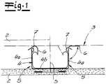
- a drywall ceiling or drywall is shown, which is evident from the Fig. 1 is equipped with a stand 1.
- the upright structure 1 is a vertical C profile rail 4 as a upright profile 4.
- a plurality of vertical C profile rails 4 are realized, which are also connected or are connected to one another by horizontal C profile rails 4 or otherwise can.
- a plurality of building panels 2 are fixed to the stud frame 1 in question.
- the building boards 2 can be plasterboard, gypsum fiber boards, wood-based boards, plastic boards, metal boards or combinations.
- a wall 3 can be clad with the aid of the building boards 2.
- the drywall ceiling or drywall wall realized in this way can also be arranged freely in a room, so that the building boards 2 are located on both sides of the stud frame 1.
- the stand profile 4 is a C profile rail 4 with C legs 4a and a C base 4b.
- the building boards 2 are fixed in the context of the invention with the aid of a fastening element 5 on the upright profile 4.
- the fastening element 5 is essentially U-shaped.
- the fastening element 5 has two fastening legs 5a and a fastening base 5b.
- the fastening element 5 is equipped with tab ends 6 and hooks 7.
- two hooks 7 are realized, which are arranged on both sides of the tab end 6 located between them. Both the hooks 7 and the respective strap end 6 are connected on the head side to the associated fastening leg 5a or extend on the head side of the respective fastening leg 5a.
- the design is such that the two hooks 7 and the respective strap end 6 are at approximately the same distance from the common fastening base 5b and, as already described, are each connected on the head side to the associated fastening leg 5a.
- a material weakening zone 8 is interposed at this point.
- the material weakening zone 8 is a perforation 8. This means that the fastening leg 5a initially merges into the material weakening zone or perforation 8 on the head side, to which the respective tab end 6 then adjoins.
- the respective hooks 7 are realized on both sides of the material weakening zone 8 or the tab end 6.
- the respective hooks 7 are designed as spring hooks.
- the hooks 7 each have an inside of the fastening element 5 or inwardly directed hook head, which is pressed back resiliently when the fastening element 5 is attached to the stand profile 4 or the associated profile rail 4 and, as a rule, the associated profile leg 4a of the stand profile 4 at the end spreads.
- the fastening element 5 can be pre-fixed to the stand profile 4.
- the hooks or spring hooks 7 ensure that they respectively overlap or reach behind the end of the profile legs 4a, so that the fastening element 5 is fixed on the C-profile rail 4, but can still carry out a relative movement with respect to the stand profile 4, namely in the longitudinal direction of the upright profile 4.
- the fastening element 5 can be clipped, as it were, to the stand profile 4 as part of the pre-fixing, the fastening element 5 being able to be displaced along the stand profile 4 or the associated CProfile rail 4.
- the fastening element 5 can be precisely determined by a drywaller where the building board 2 to be attached to it is subsequently to be placed. Only in the course of the final fixation are the tab ends 6 placed on the respective profile leg 4a of the upright profile 4 or around the profile leg 4 in question, as is shown in FIG Fig. 1 is shown. Then the fastening element 5 is firmly connected to the stand profile 4 or end-fixed.
- the respective tab end 6 can also be placed on the profile leg 4a in question, as is the case in the left part of FIG Fig. 1 is indicated. Then, for example, a further one or more additional building boards 2 can be connected to the stand profile 4 at the rear. It is also possible that the tab end 6 is fixed to the base 3, as shown in the right part of FIG Fig. 1 will be shown. In this case, the stand profile 4 in connection with the building boards 2 may serve as cladding for the base 3.
- fastening element 5 is therefore equipped in addition to the at least two tab ends 6 for final fixing with the two hooks 7 for pre-fixing on the respective profile leg 4a of the upright profile 4. After the pre-fixing, the fastening element 5 can be moved into the desired position along the upright profile 4. The fastening element 5 is therefore equipped in addition to the at least two tab ends 6 for final fixing with the two hooks 7 for its pre-fixing on the respective profile leg 4 of the upright profile 1.
- the final fixing only takes place when its final position has been reached and corresponds to the drywaller's ideas.
- the one or the two tab ends 6 are bent. This bending process is facilitated by the intermediate perforation 8.
- the flap end 6 can be bent or bent in consideration of the material weakening zone or perforation 8 in practically any desired angle with respect to the fixed and associated fastening leg 5a.
- the tab end 6, the respective hook 7, the fastening legs 5a and finally the fastening base 5b are made of the same material from a metal and for example steel within the scope of the exemplary embodiment.
- the production can be carried out in one go by typical punching / bending steps, so that the fastening element 5 can be produced particularly easily and inexpensively.
- the fastening element 5 is typically equipped with a coating and in particular a zinc coating in order to prevent any corrosion.
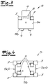
- the fastening element 5 has a mirror-symmetrical configuration in comparison to a central plane of symmetry S, which is only in the Fig. 2 is indicated. This makes production even easier.
- the U-base or fastening base 5b of the fastening element 5 is generally available for attaching the building boards 2 to the fastening element 5.
- connecting means 9 are usually used at this point, with the aid of which the respective building board 2 is fixed to the fastening element 5.
- the connecting means 9 in question may be a lug fixed to the U-base 5b or a separate screw etc.
- the connecting means 9 is designed as a nose engaging in a groove of the relevant building board 2.
- the building boards 2 can alternatively also be adhesively connected to the U-base of the fastening element 5 or - as already described - by screwing or otherwise.
- the fastening element 5 can be coupled to the profile rail 4 in fundamentally different ways. It is conceivable that in the mounted state, the fastening element 5 with its fastening legs 5a on the associated fastening legs or C-legs 4a the profile rail 4 rests.
- the U-base 5b of the fastening element 5 and the C-base 4b of the profile rail 4 can be as in FIG Fig. 1 shown also be arranged in relation to each other. As an alternative to this, however, it is also possible for the U base or fastening base 5b of the fastening element 5 and the C base 4b of the profile rail 4 to be spaced apart from one another. However, this is not shown in detail.
- the fastening means 9 can be arranged in any way on the U-base 5b of the fastening element 5. Cross arrangements and / or longitudinal arrangements are conceivable and are within the scope of the invention.
- the invention also encompasses a releasable fixing of the fastening means 9 to the respective U base 5b of the fastening element 5.
Landscapes
- Engineering & Computer Science (AREA)
- Architecture (AREA)
- Civil Engineering (AREA)
- Structural Engineering (AREA)
- Physics & Mathematics (AREA)
- Electromagnetism (AREA)
- Chemical & Material Sciences (AREA)
- Ceramic Engineering (AREA)
- Finishing Walls (AREA)
- Joining Of Building Structures In Genera (AREA)
Claims (13)
- Elément de fixation (5) pour la fixation à un profilé vertical (4) d'un plafond/mur construit à sec, dans lequel sont prévus, en plus d'au moins deux extrémités des pattes (6) pour la fixation finale, un ou plusieurs crochets (7) pour la préfixation de l'élément de fixation (5) à une aile de profilé (4a) respective du profilé vertical (4), qui sont prévus en plus d'au moins deux extrémités des pattes (6) pour la fixation finale, dans lequel l'élément de fixation (5) est constitué essentiellement en forme de U avec deux ailes de fixation (5a) et une base de fixation (5b), et dans lequel l'aile de fixation (5a) respective est équipée d'au moins une extrémité de patte (6) et d'au moins un crochet (7), caractérisé en ce que l'extrémité de patte (6) est reliée à l'aile de fixation (5a) avec interposition d'une zone d'affaiblissement du matériau (8).
- Plafond/mur construit à sec, comportant une ossature (1) et un ou plusieurs panneaux de construction (2) fixés à un profilé vertical (4) associé, dans lequel les panneaux de construction (2) sont fixés au profilé vertical (4) respectif avec l'interposition d'éléments de fixation (5) selon la revendication 1, et à cette fin, l'élément de fixation (5) est équipé d'extrémités des pattes (6) qui s'engagent autour des ailes de profilé (4a) du profilé vertical (4), l'élément de fixation (5) étant équipé, en plus des au moins deux extrémités des pattes (6) pour la fixation finale, avec un ou plusieurs crochets (7) pour la préfixation de l'élément de fixation (5) sur l'aile de profilé (4a) respective du profilé vertical (4), l'élément de fixation (5) étant constitué essentiellement en forme de U avec deux ailes de fixation (5a) et une base de fixation (5b), l'aile de fixation (5a) respective étant équipée d'au moins une extrémité de patte (6) et d'au moins un crochet (7), caractérisé en ce que l'extrémité de patte (6) est reliée à l'aile de fixation (5a) avec interposition d'une zone d'affaiblissement de matériau (8).
- Plafond/mur construit à sec selon la revendication 2, caractérisé en ce que les extrémités des pattes (6) permettent, lors de la préfixation, un mouvement relatif de l'élément de fixation (5) par rapport au profilé vertical (4), ledit mouvement étant guidé par le crochet (7).
- Plafond/mur construit à sec selon la revendication 2 ou 3, caractérisé en ce que les extrémités des pattes (6) pour la fixation finale de l'élément de fixation (5) sont placées autour de l'aile de profilé (4a) du profilé vertical (4) et/ou sont fixées à l'aile de profilé (4a) et/ou sont ancrées à une base (3).
- Plafond/mur construit à sec selon la revendication 2, caractérisé en ce que deux crochets (7) sont prévus des deux côtés de l'extrémité de patte (6) située entre ceux-ci.
- Plafond/mur construit à sec selon la revendication 2 ou 5, caractérisé en ce que le crochet (7) et l'extrémité de patte (6) sont reliés à l'extrémité supérieure de l'aile de fixation (5a) correspondante à une distance à peu près identique de la base de fixation (5b).
- Plafond/mur construit à sec selon la revendication 2, caractérisé en ce que la zone d'affaiblissement du matériau (8) est constituée comme une perforation (8).
- Plafond/mur construit à sec selon la revendication 2 ou 5 à 7, caractérisé en ce que l'extrémité de patte (6), le crochet (7) et les ailes de fixation (5a) ainsi que la base de fixation (5b) sont fabriqués à partir d'un matériau uniforme, par exemple l'acier.
- Plafond/mur construit à sec selon l'une des revendications 2 à 7, caractérisé en ce que l'élément de fixation (5) est constitué de manière symétrique par rapport à un plan de symétrie central (S).
- Plafond/mur construit à sec selon l'une des revendications 2 à 9, caractérisé en ce que l'élément de fixation (5) comporte un revêtement, par exemple un revêtement de zinc, comme protection contre la corrosion.
- Plafond/mur construit à sec selon l'une des revendications 2 à 10, caractérisé en ce que la base de fixation (5b) de l'élément de fixation (5) est équipée de moyens de liaison (9) pour la fixation des panneaux de construction (2).
- Plafond/mur construit à sec selon l'une des revendications 2 à 11, caractérisé en ce que l'ossature (1) est constituée de rails profilés en C (4) s'étendant essentiellement verticalement et/ou horizontalement sous la forme d'un profilé vertical (4) dans chaque cas.
- Plafond/mur construit à sec selon la revendication 12, caractérisé en ce que l'élément de fixation (5), à l'état monté sur le rail profilé en C (4), repose avec ses ailes de fixation (5a) respectivement contre les ailes en C (4a), tandis que la base de fixation (5b) et une base en C (4b) sont également disposées en contact l'une avec l'autre ou espacées l'une de l'autre.
Applications Claiming Priority (2)
| Application Number | Priority Date | Filing Date | Title |
|---|---|---|---|
| DE202013100161U DE202013100161U1 (de) | 2013-01-11 | 2013-01-11 | Trockenbaudecke/-wand |
| PCT/EP2014/050511 WO2014108543A1 (fr) | 2013-01-11 | 2014-01-13 | Cloison sèche |
Publications (2)
| Publication Number | Publication Date |
|---|---|
| EP2943625A1 EP2943625A1 (fr) | 2015-11-18 |
| EP2943625B1 true EP2943625B1 (fr) | 2020-05-13 |
Family
ID=47991202
Family Applications (1)
| Application Number | Title | Priority Date | Filing Date |
|---|---|---|---|
| EP14700385.9A Active EP2943625B1 (fr) | 2013-01-11 | 2014-01-13 | Cloison sèche |
Country Status (5)
| Country | Link |
|---|---|
| US (1) | US9657481B2 (fr) |
| EP (1) | EP2943625B1 (fr) |
| DE (1) | DE202013100161U1 (fr) |
| DK (1) | DK2943625T3 (fr) |
| WO (1) | WO2014108543A1 (fr) |
Families Citing this family (9)
| Publication number | Priority date | Publication date | Assignee | Title |
|---|---|---|---|---|
| USD743578S1 (en) | 2013-01-15 | 2015-11-17 | Placoplatre | Building panel |
| DE102013106880A1 (de) * | 2013-07-01 | 2015-01-08 | Saint-Gobain Rigips Gmbh | Trockenbausystem zur Erstellung von Trennwänden, abgehängten Decken oder dgl., Trägerprofil hierfür sowie Verwendung dieses Trockenbausystems |
| GB2540443B (en) * | 2015-11-06 | 2018-10-31 | Thomas Smart Hugh | A kit of parts for fixing a plurality of cladding boards to a surface |
| NL1041856B1 (en) * | 2016-05-09 | 2017-11-16 | Hunter Douglas Ind Bv | Panels Spilce Connector for Linear Panels. |
| US10060460B1 (en) | 2017-07-05 | 2018-08-28 | Brandon C. Winn | Precursor for a furring channel clip, furring channel clip formed therefrom, method of making a furring channel clip, and method of mounting a furring channel to a load bearing member |
| EP3587693B1 (fr) * | 2018-06-29 | 2023-01-04 | Certainteed Canada, Inc. | Pince de connexion pour la fixation d'un panneau sur une grille de support |
| USD956268S1 (en) | 2019-08-01 | 2022-06-28 | Hunter Douglas Industries B.V. | Ceiling panel |
| GB2595896A (en) * | 2020-06-10 | 2021-12-15 | Reform Systems Ltd | Panel mounting system |
| IT202000027453A1 (it) * | 2020-11-16 | 2022-05-16 | Manni Green Tech S R L | Profilato per telaio di pareti |
Family Cites Families (12)
| Publication number | Priority date | Publication date | Assignee | Title |
|---|---|---|---|---|
| US2056328A (en) | 1933-12-05 | 1936-10-06 | George M Soule | System of wall construction |
| US3232018A (en) | 1962-11-13 | 1966-02-01 | Dominion Bridge Co Ltd | Resilient clip securing panels in spaced relation to wall studs |
| US3962840A (en) | 1973-03-22 | 1976-06-15 | United States Gypsum Company | Corner construction and clip therefor |
| US4395858A (en) * | 1981-07-06 | 1983-08-02 | Gwyther Donald W | Panel mounting system and method |
| GB2120702B (en) * | 1982-05-25 | 1985-09-04 | Hunter Douglas Ind Bv | Clip for wall or ceiling panel structure |
| EP0206146B1 (fr) * | 1985-06-26 | 1989-03-15 | Hunter Douglas Industries B.V. | Sous-structure pour revêtements de bâtiments |
| US5245811A (en) * | 1991-03-14 | 1993-09-21 | William L. Knorr | Wall framing clip system |
| IES60089B2 (en) * | 1992-10-19 | 1994-06-01 | T & T Fixings Ltd | Improvements in or relating to construction of suspended ceilings, walls and partition walls |
| DE29611333U1 (de) | 1996-06-28 | 1996-09-05 | Wisan Technik AG, Zug | Befestigungselement mit Träger |
| WO2005072130A2 (fr) | 2004-01-16 | 2005-08-11 | Construction Solutions, Llc | Clip de support de mur sec |
| US7856777B2 (en) * | 2006-11-06 | 2010-12-28 | Haworth, Inc. | Clip arrangement for wall panel tiles |
| DE202013007676U1 (de) * | 2013-08-28 | 2014-12-01 | Huwer GmbH | Verbindungselement für Profilschienen |
-
2013
- 2013-01-11 DE DE202013100161U patent/DE202013100161U1/de not_active Expired - Lifetime
-
2014
- 2014-01-13 US US14/758,869 patent/US9657481B2/en not_active Expired - Fee Related
- 2014-01-13 DK DK14700385.9T patent/DK2943625T3/da active
- 2014-01-13 WO PCT/EP2014/050511 patent/WO2014108543A1/fr not_active Ceased
- 2014-01-13 EP EP14700385.9A patent/EP2943625B1/fr active Active
Non-Patent Citations (1)
| Title |
|---|
| None * |
Also Published As
| Publication number | Publication date |
|---|---|
| WO2014108543A1 (fr) | 2014-07-17 |
| DE202013100161U1 (de) | 2013-02-25 |
| EP2943625A1 (fr) | 2015-11-18 |
| US20150337538A1 (en) | 2015-11-26 |
| DK2943625T3 (da) | 2020-07-13 |
| US9657481B2 (en) | 2017-05-23 |
Similar Documents
| Publication | Publication Date | Title |
|---|---|---|
| DE202013100161U1 (de) | Trockenbaudecke/-wand | |
| DE202009011708U1 (de) | Befestigungselement | |
| EP2416042A2 (fr) | Dispositif de suspension réglable | |
| DE202017102837U1 (de) | Paneele für ein dreidimensionales Dekor von Wand- und Deckenpaneelen | |
| EP3548412B1 (fr) | Dispositif de fixation et procédé permettant de fixer un élément de paroi dans une cabine d'ascenseur | |
| DE102015111880B4 (de) | Vorrichtung zum Befestigen von PV-Modulen an Profilen sowie Montageverfahren | |
| EP2945828B1 (fr) | Dispositif de montage pour un élément d'habillage de paroi latérale d'un véhicule ferroviaire | |
| EP2946972A2 (fr) | Systeme de fixation pour des elements d'amenagement interieur de vehicule utilitaire | |
| EP3103956A1 (fr) | Profile porteur modulaire comprenant des logements de barres | |
| DE102010008668A1 (de) | Verbindungssystem und Verfahren zum Herstellen eines Verbindungssystems | |
| AT509393B1 (de) | Wandstütze | |
| DE202008002720U1 (de) | Verbindungsvorrichtung für Wand- oder Verkleidungselemente | |
| EP2098800A2 (fr) | Dispositif de montage d'appareils thermodynamiques suspendus au mur | |
| EP3910125A1 (fr) | Bâti de support permettant de suspendre au moins un absorbeur de son provenant du plafond, système d'amélioration de l'acoustique dans une pièce | |
| EP3130716B1 (fr) | Panneau de mur et systeme de panneaux de mur pour la construction de stand d'exposition | |
| DE202013104418U1 (de) | Fassadenkonsole sowie Fassadenkonstruktion | |
| EP3561199A1 (fr) | Élément de raccordement pour coffrages et procédé de raccordement du coffrage | |
| AT406174B (de) | Befestigungsteil für profile | |
| DE102009003910A1 (de) | Tragschiene für eine Vorrichtung zur Halterung von Wandplatten an einer Wand sowie Fassadenbekleidung | |
| DE202022106604U1 (de) | Fahrkorb für eine Aufzugsanlage | |
| AT15567U1 (de) | Verbindung zweier Holzbalken | |
| EP0813278B1 (fr) | Plaque de tête en tôle préformée | |
| DE202005006462U1 (de) | Flexibles Profil | |
| DE102015010031B4 (de) | Rahmen für eine Leuchte | |
| DE202013104951U1 (de) | Montagesystem für Armaturen an einer Leichtbauwand |
Legal Events
| Date | Code | Title | Description |
|---|---|---|---|
| PUAI | Public reference made under article 153(3) epc to a published international application that has entered the european phase |
Free format text: ORIGINAL CODE: 0009012 |
|
| 17P | Request for examination filed |
Effective date: 20150709 |
|
| AK | Designated contracting states |
Kind code of ref document: A1 Designated state(s): AL AT BE BG CH CY CZ DE DK EE ES FI FR GB GR HR HU IE IS IT LI LT LU LV MC MK MT NL NO PL PT RO RS SE SI SK SM TR |
|
| AX | Request for extension of the european patent |
Extension state: BA ME |
|
| RIN1 | Information on inventor provided before grant (corrected) |
Inventor name: FLORENSKE, OLIVER Inventor name: MITTNACHT, SEBASTIAN |
|
| RIN1 | Information on inventor provided before grant (corrected) |
Inventor name: MITTNACHT, SEBASTIAN Inventor name: FLORENSKE, OLIVER |
|
| DAX | Request for extension of the european patent (deleted) | ||
| 17Q | First examination report despatched |
Effective date: 20160826 |
|
| STAA | Information on the status of an ep patent application or granted ep patent |
Free format text: STATUS: EXAMINATION IS IN PROGRESS |
|
| GRAP | Despatch of communication of intention to grant a patent |
Free format text: ORIGINAL CODE: EPIDOSNIGR1 |
|
| STAA | Information on the status of an ep patent application or granted ep patent |
Free format text: STATUS: GRANT OF PATENT IS INTENDED |
|
| RIC1 | Information provided on ipc code assigned before grant |
Ipc: E04F 13/14 20060101ALI20190919BHEP Ipc: E04F 13/08 20060101ALI20190919BHEP Ipc: E04B 2/74 20060101AFI20190919BHEP Ipc: E04B 9/10 20060101ALN20190919BHEP Ipc: E04B 1/41 20060101ALI20190919BHEP Ipc: E04B 9/26 20060101ALN20190919BHEP Ipc: E04B 1/24 20060101ALN20190919BHEP Ipc: E04B 9/28 20060101ALN20190919BHEP |
|
| RIC1 | Information provided on ipc code assigned before grant |
Ipc: E04B 1/24 20060101ALN20190926BHEP Ipc: E04B 2/74 20060101AFI20190926BHEP Ipc: E04B 9/28 20060101ALN20190926BHEP Ipc: E04B 9/10 20060101ALN20190926BHEP Ipc: E04F 13/14 20060101ALI20190926BHEP Ipc: E04B 9/26 20060101ALN20190926BHEP Ipc: E04B 1/41 20060101ALI20190926BHEP Ipc: E04F 13/08 20060101ALI20190926BHEP |
|
| INTG | Intention to grant announced |
Effective date: 20191011 |
|
| GRAJ | Information related to disapproval of communication of intention to grant by the applicant or resumption of examination proceedings by the epo deleted |
Free format text: ORIGINAL CODE: EPIDOSDIGR1 |
|
| REG | Reference to a national code |
Ref country code: DE Ref legal event code: R079 Ref document number: 502014014174 Country of ref document: DE Free format text: PREVIOUS MAIN CLASS: E04F0013080000 Ipc: E04B0002740000 |
|
| STAA | Information on the status of an ep patent application or granted ep patent |
Free format text: STATUS: EXAMINATION IS IN PROGRESS |
|
| GRAP | Despatch of communication of intention to grant a patent |
Free format text: ORIGINAL CODE: EPIDOSNIGR1 |
|
| STAA | Information on the status of an ep patent application or granted ep patent |
Free format text: STATUS: GRANT OF PATENT IS INTENDED |
|
| INTC | Intention to grant announced (deleted) | ||
| RIC1 | Information provided on ipc code assigned before grant |
Ipc: E04B 9/10 20060101ALN20191113BHEP Ipc: E04B 9/26 20060101ALN20191113BHEP Ipc: E04F 13/14 20060101ALI20191113BHEP Ipc: E04B 2/74 20060101AFI20191113BHEP Ipc: E04B 1/41 20060101ALI20191113BHEP Ipc: E04F 13/08 20060101ALI20191113BHEP Ipc: E04B 1/24 20060101ALN20191113BHEP Ipc: E04B 9/28 20060101ALN20191113BHEP |
|
| INTG | Intention to grant announced |
Effective date: 20191125 |
|
| GRAS | Grant fee paid |
Free format text: ORIGINAL CODE: EPIDOSNIGR3 |
|
| GRAA | (expected) grant |
Free format text: ORIGINAL CODE: 0009210 |
|
| STAA | Information on the status of an ep patent application or granted ep patent |
Free format text: STATUS: THE PATENT HAS BEEN GRANTED |
|
| AK | Designated contracting states |
Kind code of ref document: B1 Designated state(s): AL AT BE BG CH CY CZ DE DK EE ES FI FR GB GR HR HU IE IS IT LI LT LU LV MC MK MT NL NO PL PT RO RS SE SI SK SM TR |
|
| REG | Reference to a national code |
Ref country code: GB Ref legal event code: FG4D Free format text: NOT ENGLISH |
|
| REG | Reference to a national code |
Ref country code: CH Ref legal event code: EP |
|
| REG | Reference to a national code |
Ref country code: DE Ref legal event code: R096 Ref document number: 502014014174 Country of ref document: DE |
|
| REG | Reference to a national code |
Ref country code: AT Ref legal event code: REF Ref document number: 1270455 Country of ref document: AT Kind code of ref document: T Effective date: 20200615 |
|
| REG | Reference to a national code |
Ref country code: DK Ref legal event code: T3 Effective date: 20200707 |
|
| REG | Reference to a national code |
Ref country code: FI Ref legal event code: FGE |
|
| REG | Reference to a national code |
Ref country code: LT Ref legal event code: MG4D |
|
| REG | Reference to a national code |
Ref country code: NL Ref legal event code: MP Effective date: 20200513 |
|
| PG25 | Lapsed in a contracting state [announced via postgrant information from national office to epo] |
Ref country code: SE Free format text: LAPSE BECAUSE OF FAILURE TO SUBMIT A TRANSLATION OF THE DESCRIPTION OR TO PAY THE FEE WITHIN THE PRESCRIBED TIME-LIMIT Effective date: 20200513 Ref country code: LT Free format text: LAPSE BECAUSE OF FAILURE TO SUBMIT A TRANSLATION OF THE DESCRIPTION OR TO PAY THE FEE WITHIN THE PRESCRIBED TIME-LIMIT Effective date: 20200513 Ref country code: PT Free format text: LAPSE BECAUSE OF FAILURE TO SUBMIT A TRANSLATION OF THE DESCRIPTION OR TO PAY THE FEE WITHIN THE PRESCRIBED TIME-LIMIT Effective date: 20200914 Ref country code: IS Free format text: LAPSE BECAUSE OF FAILURE TO SUBMIT A TRANSLATION OF THE DESCRIPTION OR TO PAY THE FEE WITHIN THE PRESCRIBED TIME-LIMIT Effective date: 20200913 Ref country code: NO Free format text: LAPSE BECAUSE OF FAILURE TO SUBMIT A TRANSLATION OF THE DESCRIPTION OR TO PAY THE FEE WITHIN THE PRESCRIBED TIME-LIMIT Effective date: 20200813 Ref country code: GR Free format text: LAPSE BECAUSE OF FAILURE TO SUBMIT A TRANSLATION OF THE DESCRIPTION OR TO PAY THE FEE WITHIN THE PRESCRIBED TIME-LIMIT Effective date: 20200814 |
|
| PG25 | Lapsed in a contracting state [announced via postgrant information from national office to epo] |
Ref country code: RS Free format text: LAPSE BECAUSE OF FAILURE TO SUBMIT A TRANSLATION OF THE DESCRIPTION OR TO PAY THE FEE WITHIN THE PRESCRIBED TIME-LIMIT Effective date: 20200513 Ref country code: HR Free format text: LAPSE BECAUSE OF FAILURE TO SUBMIT A TRANSLATION OF THE DESCRIPTION OR TO PAY THE FEE WITHIN THE PRESCRIBED TIME-LIMIT Effective date: 20200513 Ref country code: LV Free format text: LAPSE BECAUSE OF FAILURE TO SUBMIT A TRANSLATION OF THE DESCRIPTION OR TO PAY THE FEE WITHIN THE PRESCRIBED TIME-LIMIT Effective date: 20200513 Ref country code: BG Free format text: LAPSE BECAUSE OF FAILURE TO SUBMIT A TRANSLATION OF THE DESCRIPTION OR TO PAY THE FEE WITHIN THE PRESCRIBED TIME-LIMIT Effective date: 20200813 |
|
| PG25 | Lapsed in a contracting state [announced via postgrant information from national office to epo] |
Ref country code: NL Free format text: LAPSE BECAUSE OF FAILURE TO SUBMIT A TRANSLATION OF THE DESCRIPTION OR TO PAY THE FEE WITHIN THE PRESCRIBED TIME-LIMIT Effective date: 20200513 Ref country code: AL Free format text: LAPSE BECAUSE OF FAILURE TO SUBMIT A TRANSLATION OF THE DESCRIPTION OR TO PAY THE FEE WITHIN THE PRESCRIBED TIME-LIMIT Effective date: 20200513 |
|
| PG25 | Lapsed in a contracting state [announced via postgrant information from national office to epo] |
Ref country code: SM Free format text: LAPSE BECAUSE OF FAILURE TO SUBMIT A TRANSLATION OF THE DESCRIPTION OR TO PAY THE FEE WITHIN THE PRESCRIBED TIME-LIMIT Effective date: 20200513 Ref country code: RO Free format text: LAPSE BECAUSE OF FAILURE TO SUBMIT A TRANSLATION OF THE DESCRIPTION OR TO PAY THE FEE WITHIN THE PRESCRIBED TIME-LIMIT Effective date: 20200513 Ref country code: IT Free format text: LAPSE BECAUSE OF FAILURE TO SUBMIT A TRANSLATION OF THE DESCRIPTION OR TO PAY THE FEE WITHIN THE PRESCRIBED TIME-LIMIT Effective date: 20200513 Ref country code: CZ Free format text: LAPSE BECAUSE OF FAILURE TO SUBMIT A TRANSLATION OF THE DESCRIPTION OR TO PAY THE FEE WITHIN THE PRESCRIBED TIME-LIMIT Effective date: 20200513 Ref country code: ES Free format text: LAPSE BECAUSE OF FAILURE TO SUBMIT A TRANSLATION OF THE DESCRIPTION OR TO PAY THE FEE WITHIN THE PRESCRIBED TIME-LIMIT Effective date: 20200513 Ref country code: EE Free format text: LAPSE BECAUSE OF FAILURE TO SUBMIT A TRANSLATION OF THE DESCRIPTION OR TO PAY THE FEE WITHIN THE PRESCRIBED TIME-LIMIT Effective date: 20200513 |
|
| REG | Reference to a national code |
Ref country code: DE Ref legal event code: R097 Ref document number: 502014014174 Country of ref document: DE |
|
| PG25 | Lapsed in a contracting state [announced via postgrant information from national office to epo] |
Ref country code: PL Free format text: LAPSE BECAUSE OF FAILURE TO SUBMIT A TRANSLATION OF THE DESCRIPTION OR TO PAY THE FEE WITHIN THE PRESCRIBED TIME-LIMIT Effective date: 20200513 Ref country code: SK Free format text: LAPSE BECAUSE OF FAILURE TO SUBMIT A TRANSLATION OF THE DESCRIPTION OR TO PAY THE FEE WITHIN THE PRESCRIBED TIME-LIMIT Effective date: 20200513 |
|
| PLBE | No opposition filed within time limit |
Free format text: ORIGINAL CODE: 0009261 |
|
| STAA | Information on the status of an ep patent application or granted ep patent |
Free format text: STATUS: NO OPPOSITION FILED WITHIN TIME LIMIT |
|
| 26N | No opposition filed |
Effective date: 20210216 |
|
| PG25 | Lapsed in a contracting state [announced via postgrant information from national office to epo] |
Ref country code: SI Free format text: LAPSE BECAUSE OF FAILURE TO SUBMIT A TRANSLATION OF THE DESCRIPTION OR TO PAY THE FEE WITHIN THE PRESCRIBED TIME-LIMIT Effective date: 20200513 |
|
| PG25 | Lapsed in a contracting state [announced via postgrant information from national office to epo] |
Ref country code: MC Free format text: LAPSE BECAUSE OF FAILURE TO SUBMIT A TRANSLATION OF THE DESCRIPTION OR TO PAY THE FEE WITHIN THE PRESCRIBED TIME-LIMIT Effective date: 20200513 |
|
| REG | Reference to a national code |
Ref country code: CH Ref legal event code: PL |
|
| PG25 | Lapsed in a contracting state [announced via postgrant information from national office to epo] |
Ref country code: LU Free format text: LAPSE BECAUSE OF NON-PAYMENT OF DUE FEES Effective date: 20210113 |
|
| REG | Reference to a national code |
Ref country code: BE Ref legal event code: MM Effective date: 20210131 |
|
| PG25 | Lapsed in a contracting state [announced via postgrant information from national office to epo] |
Ref country code: FR Free format text: LAPSE BECAUSE OF NON-PAYMENT OF DUE FEES Effective date: 20210131 |
|
| PG25 | Lapsed in a contracting state [announced via postgrant information from national office to epo] |
Ref country code: LI Free format text: LAPSE BECAUSE OF NON-PAYMENT OF DUE FEES Effective date: 20210131 Ref country code: CH Free format text: LAPSE BECAUSE OF NON-PAYMENT OF DUE FEES Effective date: 20210131 |
|
| REG | Reference to a national code |
Ref country code: AT Ref legal event code: MM01 Ref document number: 1270455 Country of ref document: AT Kind code of ref document: T Effective date: 20210113 |
|
| PG25 | Lapsed in a contracting state [announced via postgrant information from national office to epo] |
Ref country code: AT Free format text: LAPSE BECAUSE OF NON-PAYMENT OF DUE FEES Effective date: 20210113 |
|
| PG25 | Lapsed in a contracting state [announced via postgrant information from national office to epo] |
Ref country code: BE Free format text: LAPSE BECAUSE OF NON-PAYMENT OF DUE FEES Effective date: 20210131 |
|
| PG25 | Lapsed in a contracting state [announced via postgrant information from national office to epo] |
Ref country code: HU Free format text: LAPSE BECAUSE OF FAILURE TO SUBMIT A TRANSLATION OF THE DESCRIPTION OR TO PAY THE FEE WITHIN THE PRESCRIBED TIME-LIMIT; INVALID AB INITIO Effective date: 20140113 |
|
| PG25 | Lapsed in a contracting state [announced via postgrant information from national office to epo] |
Ref country code: CY Free format text: LAPSE BECAUSE OF FAILURE TO SUBMIT A TRANSLATION OF THE DESCRIPTION OR TO PAY THE FEE WITHIN THE PRESCRIBED TIME-LIMIT Effective date: 20200513 |
|
| P01 | Opt-out of the competence of the unified patent court (upc) registered |
Effective date: 20230822 |
|
| PG25 | Lapsed in a contracting state [announced via postgrant information from national office to epo] |
Ref country code: MK Free format text: LAPSE BECAUSE OF FAILURE TO SUBMIT A TRANSLATION OF THE DESCRIPTION OR TO PAY THE FEE WITHIN THE PRESCRIBED TIME-LIMIT Effective date: 20200513 |
|
| PG25 | Lapsed in a contracting state [announced via postgrant information from national office to epo] |
Ref country code: MT Free format text: LAPSE BECAUSE OF FAILURE TO SUBMIT A TRANSLATION OF THE DESCRIPTION OR TO PAY THE FEE WITHIN THE PRESCRIBED TIME-LIMIT Effective date: 20200513 |
|
| PG25 | Lapsed in a contracting state [announced via postgrant information from national office to epo] |
Ref country code: TR Free format text: LAPSE BECAUSE OF FAILURE TO SUBMIT A TRANSLATION OF THE DESCRIPTION OR TO PAY THE FEE WITHIN THE PRESCRIBED TIME-LIMIT Effective date: 20200513 |
|
| PGFP | Annual fee paid to national office [announced via postgrant information from national office to epo] |
Ref country code: GB Payment date: 20260127 Year of fee payment: 13 |
|
| PGFP | Annual fee paid to national office [announced via postgrant information from national office to epo] |
Ref country code: DE Payment date: 20260128 Year of fee payment: 13 Ref country code: DK Payment date: 20260126 Year of fee payment: 13 Ref country code: IE Payment date: 20260127 Year of fee payment: 13 |
|
| PGFP | Annual fee paid to national office [announced via postgrant information from national office to epo] |
Ref country code: FI Payment date: 20260126 Year of fee payment: 13 |