EP2943682B1 - Structure de support pour générateurs éoliens d'énergie électrique de divers types - Google Patents
Structure de support pour générateurs éoliens d'énergie électrique de divers types Download PDFInfo
- Publication number
- EP2943682B1 EP2943682B1 EP14703411.0A EP14703411A EP2943682B1 EP 2943682 B1 EP2943682 B1 EP 2943682B1 EP 14703411 A EP14703411 A EP 14703411A EP 2943682 B1 EP2943682 B1 EP 2943682B1
- Authority
- EP
- European Patent Office
- Prior art keywords
- support structure
- section bar
- same
- section bars
- rectilinear
- Prior art date
- Legal status (The legal status is an assumption and is not a legal conclusion. Google has not performed a legal analysis and makes no representation as to the accuracy of the status listed.)
- Active
Links
- 230000008878 coupling Effects 0.000 claims description 8
- 238000010168 coupling process Methods 0.000 claims description 8
- 238000005859 coupling reaction Methods 0.000 claims description 8
- 239000000463 material Substances 0.000 claims description 8
- 230000001360 synchronised effect Effects 0.000 claims description 2
- 238000009415 formwork Methods 0.000 claims 2
- 238000009434 installation Methods 0.000 description 5
- 238000004873 anchoring Methods 0.000 description 2
- 238000006073 displacement reaction Methods 0.000 description 2
- 230000005674 electromagnetic induction Effects 0.000 description 1
- 238000012423 maintenance Methods 0.000 description 1
- 238000004519 manufacturing process Methods 0.000 description 1
- 230000002093 peripheral effect Effects 0.000 description 1
Images





Classifications
-
- F—MECHANICAL ENGINEERING; LIGHTING; HEATING; WEAPONS; BLASTING
- F03—MACHINES OR ENGINES FOR LIQUIDS; WIND, SPRING, OR WEIGHT MOTORS; PRODUCING MECHANICAL POWER OR A REACTIVE PROPULSIVE THRUST, NOT OTHERWISE PROVIDED FOR
- F03D—WIND MOTORS
- F03D13/00—Assembly, mounting or commissioning of wind motors; Arrangements specially adapted for transporting wind motor components
- F03D13/20—Arrangements for mounting or supporting wind motors; Masts or towers for wind motors
-
- F—MECHANICAL ENGINEERING; LIGHTING; HEATING; WEAPONS; BLASTING
- F03—MACHINES OR ENGINES FOR LIQUIDS; WIND, SPRING, OR WEIGHT MOTORS; PRODUCING MECHANICAL POWER OR A REACTIVE PROPULSIVE THRUST, NOT OTHERWISE PROVIDED FOR
- F03D—WIND MOTORS
- F03D9/00—Adaptations of wind motors for special use; Combinations of wind motors with apparatus driven thereby; Wind motors specially adapted for installation in particular locations
- F03D9/20—Wind motors characterised by the driven apparatus
- F03D9/25—Wind motors characterised by the driven apparatus the apparatus being an electrical generator
-
- F—MECHANICAL ENGINEERING; LIGHTING; HEATING; WEAPONS; BLASTING
- F05—INDEXING SCHEMES RELATING TO ENGINES OR PUMPS IN VARIOUS SUBCLASSES OF CLASSES F01-F04
- F05B—INDEXING SCHEME RELATING TO WIND, SPRING, WEIGHT, INERTIA OR LIKE MOTORS, TO MACHINES OR ENGINES FOR LIQUIDS COVERED BY SUBCLASSES F03B, F03D AND F03G
- F05B2240/00—Components
- F05B2240/90—Mounting on supporting structures or systems
- F05B2240/91—Mounting on supporting structures or systems on a stationary structure
- F05B2240/916—Mounting on supporting structures or systems on a stationary structure with provision for hoisting onto the structure
-
- F—MECHANICAL ENGINEERING; LIGHTING; HEATING; WEAPONS; BLASTING
- F05—INDEXING SCHEMES RELATING TO ENGINES OR PUMPS IN VARIOUS SUBCLASSES OF CLASSES F01-F04
- F05B—INDEXING SCHEME RELATING TO WIND, SPRING, WEIGHT, INERTIA OR LIKE MOTORS, TO MACHINES OR ENGINES FOR LIQUIDS COVERED BY SUBCLASSES F03B, F03D AND F03G
- F05B2240/00—Components
- F05B2240/90—Mounting on supporting structures or systems
- F05B2240/91—Mounting on supporting structures or systems on a stationary structure
- F05B2240/917—Mounting on supporting structures or systems on a stationary structure attached to cables
-
- Y—GENERAL TAGGING OF NEW TECHNOLOGICAL DEVELOPMENTS; GENERAL TAGGING OF CROSS-SECTIONAL TECHNOLOGIES SPANNING OVER SEVERAL SECTIONS OF THE IPC; TECHNICAL SUBJECTS COVERED BY FORMER USPC CROSS-REFERENCE ART COLLECTIONS [XRACs] AND DIGESTS
- Y02—TECHNOLOGIES OR APPLICATIONS FOR MITIGATION OR ADAPTATION AGAINST CLIMATE CHANGE
- Y02B—CLIMATE CHANGE MITIGATION TECHNOLOGIES RELATED TO BUILDINGS, e.g. HOUSING, HOUSE APPLIANCES OR RELATED END-USER APPLICATIONS
- Y02B10/00—Integration of renewable energy sources in buildings
- Y02B10/30—Wind power
-
- Y—GENERAL TAGGING OF NEW TECHNOLOGICAL DEVELOPMENTS; GENERAL TAGGING OF CROSS-SECTIONAL TECHNOLOGIES SPANNING OVER SEVERAL SECTIONS OF THE IPC; TECHNICAL SUBJECTS COVERED BY FORMER USPC CROSS-REFERENCE ART COLLECTIONS [XRACs] AND DIGESTS
- Y02—TECHNOLOGIES OR APPLICATIONS FOR MITIGATION OR ADAPTATION AGAINST CLIMATE CHANGE
- Y02E—REDUCTION OF GREENHOUSE GAS [GHG] EMISSIONS, RELATED TO ENERGY GENERATION, TRANSMISSION OR DISTRIBUTION
- Y02E10/00—Energy generation through renewable energy sources
- Y02E10/70—Wind energy
- Y02E10/72—Wind turbines with rotation axis in wind direction
-
- Y—GENERAL TAGGING OF NEW TECHNOLOGICAL DEVELOPMENTS; GENERAL TAGGING OF CROSS-SECTIONAL TECHNOLOGIES SPANNING OVER SEVERAL SECTIONS OF THE IPC; TECHNICAL SUBJECTS COVERED BY FORMER USPC CROSS-REFERENCE ART COLLECTIONS [XRACs] AND DIGESTS
- Y02—TECHNOLOGIES OR APPLICATIONS FOR MITIGATION OR ADAPTATION AGAINST CLIMATE CHANGE
- Y02E—REDUCTION OF GREENHOUSE GAS [GHG] EMISSIONS, RELATED TO ENERGY GENERATION, TRANSMISSION OR DISTRIBUTION
- Y02E10/00—Energy generation through renewable energy sources
- Y02E10/70—Wind energy
- Y02E10/728—Onshore wind turbines
Definitions
- the invention concerns a support structure for electric energy eolian generators of various kind, of modular type, which can be installed and applied in the ground into limited areas for ensuring an efficient and balanced support to such generators, such as to withstand with safety to the different atmospheric conditions.
- a wind turbine assembly comprising a wind turbine, an elongate mast having a longitudinal axis, the elongate mast further including a first end and a second end, a support structure, including one or more support members, and one or more anchoring means.
- the wind turbine is connected to at or toward the first end of the elongate mast
- the support structure is connected at or toward the second end of the elongate mast
- the support members are operable to be arranged to extend radially outward from the longitudinal axis of the elongate mast
- the or each anchoring means is connected to the or each support member.
- a portable, adjustable structure for supporting an equipment unit at a distance above a support surface has a lower tower structural member placed on the support surface. Pivot support structural members are affixed to the lower tower structural member in a manner whereby the pivot support structural members are upright relative to the support surface.
- a plurality of struts are utilized to stabilize the lower tower structural member and the pivot support structural members on the support surface.
- a tower member is pivotally mounted on the pivot support structural members. The tower member has spaced opposite first and second ends.
- the equipment unit is affixed to the tower member at the first end thereof.
- the tower member is pivotally movable to a position substantially perpendicular to the support surface with the first end thereof spaced farther from the support surface than the second end thereof.
- Ballast is affixed to the tower member at the second end thereof.
- the second end of the tower member is coupled to the lower tower structural member whereby the tower member is normally upright and is pivotable, upon uncoupling of the tower member and the lower tower structural member, to position the equipment unit close to the support surface for maintenance and repair.
- the object of the present invention is to realize a support structure for electric energy eolian generators made in a manner different than that disclosed the state of the art represented by WO2012/153137A1 and by US4590718A .
- a support structure adapted to support electric energy eolian generators of various kind, made with relatively limited sizes, provided for generating electric energy, particularly for being installed near inhabited environments, and preset for operating also under condition of strong wind, in order to generate electric energy for the use into the same environments, or also for the use by other users.
- These eolian generators naturally, may be realized also with greater sizes for being installed, alone or together with other analogous eolian generators, at places far-away from the inhabited areas in order to generate electric energy in a sufficient quantity for supplying a high numbers of consumers.
- Each eolian generator 5 is substantially constituted as usual by a synchronous electric generator (not shown), formed by a movable circular rotor and by a stationary circular stator (both not shown), which are contained into a stationary and metallic box-like envelope 6, supported as it will be described onto the metallic support structure 7 of the present invention, and into which box-like envelope 6 a metallic rotor 8 is housed and supported, which is rotating with respect to this latter, which rotor is mechanically connected to the electric generator rotor and supports a set of rotating vanes 9, spaced away to each other of the same angular interval along the circumference of the rotor 8, and opportunely profiled, which vanes 9 during the installation of the eolian generator are so oriented as to receive the wind thrust with the highest possible intensity, in such a way that such vanes be actuated in rotation by the wind thrust, thereby determining the rotation of the electric generator rotor and therefore generating the electric energy by electromagnetic induction.
- the metallic rotor 8 Onto the metallic rotor 8 and onto the upper part of the support structure 7 it is also fixed in an articulated manner the front end portion of at least one rectilinear and lengthened metallic rod 10, at the rear end portion of which a metallic tail 11 is fixed and formed by a shaped plate 12 adapted to be impacted by the wind and to be shifted from time to time in the direction from which the wind arrives, in a manner to determine a correspondent rotation of the rod 10 and the metallic rotor 8, and therefore also of the rotating vanes 9, so as to orient continuously these latter in such a direction as to receive the maximum wind thrust.
- an eolian generator of this kind may be constituted by the eolian generator which is described, illustrated and claimed in the patent application for industrial invention n. PN2011A000075, filed on 18.11.2011 by the same Applicant, to which therefore reference is made for a better comprehension of the constructive and structural characteristics of the same generator.
- the eolian generator supported by the present support structure may be realized also with characteristics which are different than those of the eolian generator described in the above-mentioned patent application, thus without departing from the protection sphere of the present invention.
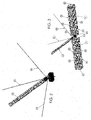
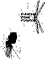
- the support structure 7 according the invention is described and how the same structure is assembled and mounted in an upright position in the relative installation position, and in particular the Figures 1-11 show a first embodiment of this support structure, with its various component parts and the different assembling phases of the same, together with the eolian generator supported by the same structure, whereas in the Figures 12-21 a second embodiment of this support structure is shown, with its various component parts and the different assembling phases of the same, together with the eolian generator supported by the same structure.
- Figure 1 illustrates an eolian generator 5 of the type referred to, with the rotating vanes 9 assembled onto the metallic rotor 8, and supported by the same, together with the rod 10 and the tail 11, which rotor 8 in turn is housed and supported into the stationary box-like envelope 6, which is supported onto the upper part of the present metallic support structure 7, in the manner that will be described.
- This metallic support structure 7 has an extension in the vertical direction, and its component parts are realized and installed to each other as it will be described, and such structure also has a relatively limited height, preferably comprised between about 3 and 20 meters, and is formed by at least a metallic rectilinear lengthened section bar 13 with vertical extent, of tubular shape, or of another suitable geometrical shape, the lower end portion of which is supported by a set of supports 14, 15, 16 and 17, joined in an articulated manner with their respective upper end portions to the vertical section bar 13 and realized as it will be described, as well as distributed uniformly on the ground around the same vertical section bar, and the respective lower end portions of such supports are fixed to correspondent ballast weights, opportunely shaped and anchored in to the ground as it will be described.
- the so realized eolian generator 5 is supported on the ground by the vertical section bar 13 always in a balanced condition, thanks to the distribution of the ballasts in an uniformly manner around the vertical section bar 13, and to the masses of such ballasts which are sized for forming counterweights exerting efficient counter-moments against the moments exerted by both the weights of the vertical section bar and the eolian generator 5 supported by it, and by the forces exerted by the wind thrusts against the rotating vanes 9, and by the forces produced by the consequent rotation of such vanes, in a way that this balanced condition be always ensured during the operation of the eolian generator 5, thereby ensuring to the same to operate always in a satisfactory and reliable manner, and preventing any danger of overturning and of non-operation of the same eolian generator.
- all the component parts of the present support structure are formed by a system of rigging stays of nautical type, which is arranged and applied in position for operating as support structure for the eolian generators, which therefore may be installed in position with simple operations and by utilizing lifting equipments of common type, which are different and less complicated and burdensome with respect to the lifting equipments such as hydraulic piston systems, oleo-dynamic systems or the like, which are nowadays used for installing the present support structures for eolian generators of these kinds.
- the four foreseen supports for supporting the vertical metallic section bar 13 are constituted by respective horizontal rectilinear section bars 14, 15, 16 and 17 with the same size, of tubular shape or other suitable geometrical shape, which form some basis struts which are arranged onto a support surface, which may be constituted by the ground or a roof of an inhabited building, and which are distributed in form of spokes around the vertical section bar 13 with the same angular distance, and the end portions converging to each other of such inclined section bars are fixed with a single central plate 18, shaped with an upper flat surface 19, into which two short projected coupling elements 20, 21 are provided, equal and spaced away to each other in the direction of the length of the flat surface 19, for assembling in an articulated manner two additional vertical section bars 22 and 23, having the same length and a tubular shape or another suitable geometrical shape, which vertical section bars are shorter than the vertical section bar 13 and are assembled in an articulated
- the free end portions of the respective horizontal section bars 14, 15, 16 and 17 are shaped as it will be described, for being articulated with the correspondent ballasts 24, 25, 26 and 27, which are identical to each other and shaped with the same shape and size, in the example they are of parallelepiped shape, but of course they may be shaped with different shapes too, thus without departing from the protection sphere of the present invention.
- Each ballast can be realized advantageously as an unique block, as in the case of the ballasts of the Figure 1 , or it may be realized with two single blocks identical and joined to each other, as in the case of the ballasts illustrated in the Figures 3 , 7-10 , wherein however each ballast contains the same weight of ballasting material.
- the vertical projected coupling elements 20 and 21 of the central plate 18 are formed by two short flat plates 28 and 29 secured onto the upper flat surface 19 of the same plate and arranged parallel and slightly spaced away to each other in the transversal direction of such plate, thereby delimiting a narrow free space into which a correspondent additional flat plate 30 and 31 may be inserted, which is secured below the free end portion of the relative rectilinear section bar 22 and 23, and provided with two respective transversal through holes 32 and 33, provided in positions correspondent to those of the relative transversal through holes 34 and 35 with which both the flat plates 28 and 29 are provided.
- each horizontal section bar 14, 15, 16 and 17 is realized with its free end portion opportunely shaped, for being articulated with the relative ballast, each one of which in the present example is constituted as already specified by two single blocks of parallelepiped shape, arranged aligned and joined to each other, which are now marked with the respective reference numerals 24', 24", 25', 25", 26', 26" and 27', 27".
- each ballast block of this kind is substantially constituted by a metallic electric welded net (not illustrated), with the same shape of the relative block, delimiting an internal cavity that is filled in advance with inert material of various kind, in equal quantity and such to obtain the desired weight of each ballast block.
- each ballast block is closed along all its sides by relative metallic (or plastic) closing walls, in the example of Figure 3 formed by a front longitudinal wall 38 and by a rear wall 39, by an upper longitudinal wall 40 and by a lower wall 41, and by an external side wall 42 and by an internal side wall 43, wherein the two internal side walls 43 opposed to each other of two ballast blocks adjacent to each other are joined to each other by a junction piece 44, welded at both these side walls, onto which a metallic articulation element 45 is secured in advance in an overlapped and interposed position, which is shaped as it will be described and provided for receiving the shaped end portion of the relative horizontal rectilinear section bar.
- relative metallic (or plastic) closing walls in the example of Figure 3 formed by a front longitudinal wall 38 and by a rear wall 39, by an upper longitudinal wall 40 and by a lower wall 41, and by an external side wall 42 and by an internal side wall 43, wherein the two internal side walls 43 opposed to each other of two ballast blocks adjacent to each other are joined to each other by
- each inclined section bar in the example constituted by the section bar 16
- each inclined section bar is shaped with a narrow vertical plate 46, formed by a tail 47 joined with the terminal part of the tubular section bar and that is extended with a slightly tapered head 48, into which there are provided at least two through holes 49 and 50 along the opposed sides of the same head, for allowing the passage of correspondent metallic stays 51 and 52 for supporting the support structure of the eolian generator.
- the tapered end portion of the head 48 is supported on and fixed to an horizontal plate 53, in turn fixed onto the upper part of the articulation element 45, the lower part of which is shaped as a square-shaped hollow sleeve 54, the longitudinal through opening 55 of which is inserted into and joined on to above-mentioned correspondent junction piece 44.
- each horizontal section bar 14-17 with the articulation element 45 may be performed also in a different manner with respect to that indicated by way of example only, thus without departing from the protection sphere of the present invention.
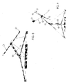
- Figures 7-9 now show the different assembling phases of the support structure 7 according to the present invention, for installing an eolian generator 5 in the foreseen installation position, and the Figure 10 shows the eolian generator 5 with the relative installed support structure 7.
- the reciprocal junction of all the component parts of the support structure 7 is effected by using a plurality of metallic stays, which are first inserted with their end portions into correspondent through holes (not indicated) provided through the relative end portions of the different component parts, and then such stays are stretched in a manner to support all the component parts in an upright position.
- the stays used to join the end portions of the different component parts of the supports structure 7 are marked with the reference numerals 51, 52, 56, 57, 58, 59 and 60, and in particular the stays 51 and 56 are directed in an inclined direction and join the respective horizontal rectilinear section bars 16 and 17 with the upper part of the vertical rectilinear section bar 13, whereas the stays 57 and 58 are also directed in an inclined direction and join the respective horizontal rectilinear section bar 14 and 15 with the upper part of the vertical rectilinear section bar 22.
- the central vertical section bar 13 supporting the eolian generator 5 is supported by an horizontal hinging element 61, of removable type, provided with three through holes adjacent and separated from each other (not indicated), through which the above-mentioned three vertical section bars 13, 22 and 23 are let to pass, in a manner that such hinging element 61 supports all these section bars in an aligned and joined position thereof, and that therefore these section bars may be shifted at the same time from the one to the other one of their inclined and upright positions.
- an horizontal hinging element 61 of removable type, provided with three through holes adjacent and separated from each other (not indicated), through which the above-mentioned three vertical section bars 13, 22 and 23 are let to pass, in a manner that such hinging element 61 supports all these section bars in an aligned and joined position thereof, and that therefore these section bars may be shifted at the same time from the one to the other one of their inclined and upright positions.
- the stays 52, 59 and 60 are directed in the horizontal direction and join the horizontal section bars 14-17 to each other, and in particular the stay 52 joins the two section bars 15 and 16, the stay 59 joins the two section bars 16 and 17 and the stay 60 joins the two section bars 17 and 14, but naturally the arrangement of the stays and their junction with the different component parts of the present support structure 7 may be effected also in different manners than those indicated by way of example only, provided that the same result be always achieved, thus without departing from the protection sphere of the present invention.
- FIGs 8 and 9 show two different assembling phases of the support structure 7 by using the above-described stays, and in particular in the phase of Figure 8 it is noted that the different ballasts 24, 25, 26 and 27 are at first placed in the respective application positions thereof, in this case onto the roof of an inhabited building, onto which it is not necessary that the same be anchored, while all the specified stays are joined with the various component parts of the support structure 7, however they are maintained loosen and not stretched among the same component parts, and under this condition the hinging element 61, which is applied onto the three section bars 13, 22 and 23, is also maintained loosen onto the same section bars, so that the two section bars 22 and 23 which are hinged to the flat plate 18 are arranged inclined with respect to the same plate, while the section bar 13 which is loose and articulated with respect to the section bars 22 and 23 may be overturned with respect to these latter, and shifted downward with its upper part 62, for fixing then onto this latter the eolian generator 5.
- the actions exerted on to the section bars and the ballast as well as the eolian generator for their displacements are performed by using preferably a traditional manually actuated winch, which is from time to time coupled to the various parts to be lowered, inclined, lifted, and overturned, which involves a limited encumbrance and may be handled, assembled and disassembled in an easy and quick manner, thereby preventing the use of some expensive and encumbering hydraulic systems, oleo-dynamic systems etc..., as hitherto was necessary to do for installing the present support structures for the eolian generators.
- the arrangement to the same level of all the component parts of the support structure in their installation position is effected by acting on to the stays through simple cable stressing devices.
- this support structure consist also in the very lower total costs, which can be estimated to be about one-third of the costs of an analogue support structure existing at the present on the market, as well as in the possibility to be able to assemble in advance in the workshop all the ballasts and to use the ballast materials such as the inert materials which can be found easily and are less expensive.
- ballasts are formed by a metallic electric welded net 63 with the same shape of the block, the internal cavity of which is again filled with inert material, and into the same a relative metallic rod 64 is secured for stiffening the structure and for fixing the respective free end portion of the horizontal section bars 14-17.
- each ballast block is closed at all sides with peripheral metallic walls (not shown), and also in this case there are used the same horizontal and vertical section bars as well as the same above-described stays, which therefore are marked with the same preceding reference numerals.
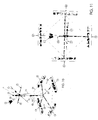
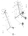
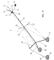
- FIG. 12-21 a second example of a support structure 65 is now shown, and in particular the Figures 14-16 illustrate the conformations of the ballasts of the present support structure, realized in a different manner with respect to the previous ones, the Figures 12 and 13 illustrate the support structure assembled with the relative eolian generator, and the Figures 17-21 show different assembling and installation phases of the support structure and the eolian generator.
- the support structure 65 is always constituted by a lengthened vertical rectilinear section bar 13, preferably of tubular shape, or also with another suitable geometrical shape, onto the upper end portion thereof the eolian generator 5 is secured and supported, and the lower end portion of which is raised from the ground and is hinged removably with three rectilinear section bars 66, 67 and 68 inclined as a strut, and having the same length, also with a tubular shape or also with another suitable shape, which are spaced away to each other of the same angular distance, thereby forming an equilateral triangle, and the free end portions of such inclined section bars 66, 67 and 68 are articulated with a respective ballast made in concrete 69, 70 and 71, as it will be described.
- the support structure 65 is constituted by a plurality of metallic stays, which join to each other all the rectilinear section bars 13, 66, 67 and 68, and the ballasts 69, 70 and 71 and these stays are also joined at a determined height with three additional rectilinear section bars 72, 73 and 74, with the same length and shorter than the preceding section bars, which have also a tubular shape or another suitable geometrical shape, and are spaced away to each other of the same angular distance, thereby forming an equilateral triangle, and act as rigging stays for the vertical lengthened section bar or pole 13.
- Figure 14 shows one of the ballasts of the present support structure, for example the ballast 70, with a portion of the relative inclined section bar 67 that is articulated with the same ballast
- Figure 15 shows the internal metallic armature 75 for forming such ballast made in concrete, together with a portion of the relative inclined section bar 67 that is articulated with the same ballast
- the Figure 16 shows the other two ballasts 69 and 71 with a portion of the relative inclined section bars 66 and 68.
- the rectilinear section bars acting as rigging stays 72, 73 and 74 are hinged with the vertical central section bar 13 and the free end portions of said rectilinear section bars are joined to each other through respective rectilinear stays 76, 77 and 78 inserted into correspondent through holes (not indicated) of these free end portions.
- Additional stays are provided for joining the different section bars of the support structure, and in particular there are provided some inclined stays directed downward, for joining the free end portions of the upper rectilinear section bars (rigging stays) 72, 73 and 74 with the free end portions of the respective lower inclined section bars 66, 67 and 68, and some inclined stays directed upward, for joining all the free end portions of such upper rectilinear section bars 72, 73 and 74 with the vertical central section bar 13, in an unique position 79 obtained along the same central section bar, at a height shorter than the upper height 80 of said central section bar 13, in which the eolian generator is fixed and supported.
- some inclined stays directed downward, for joining the free end portions of the upper rectilinear section bars (rigging stays) 72, 73 and 74 with the free end portions of the respective lower inclined section bars 66, 67 and 68, and some inclined stays directed upward, for joining all the free end portions of such upper rectilinear section bars 72, 73 and 74 with the vertical central section bar 13, in an
- stays 81 and 82 are provided for joining the free end portions of the upper rectilinear section bar 72 with the end portion of the lower section bar 66, the stays 83 and 84 for joining the free end portions of the upper section bar 73 with the end portion of the lower section bar 67, the stays 85 and 86 for joining the free end portions of the upper section bar 74 with the end portion of the lower section bar 68.
- the stays may be provided also with arrangements and quantities different than those indicated by way of non-limiting example only, for joining to each other all the section bars, always for obtaining as a result a structure with all the characteristics and advantages of the structure previously described, thus without departing from the protection sphere of the present invention.
- ballasts made in concrete 70, 71 and 69 as already specified are indicated, it is noted that the same are shaped with a cylindrical shape and provided with a metallic coupling element 87, 88 and 89, respectively, included into the concrete and shaped for coupling and fixing the respective section bars 66, 68 and 67 inclined as a strut during the assembling of the support structure.
- Each ballast is realized by assembling at first the different component parts 90, 91 and 92 of the armature 75 of the same ballast to each other (see Fig.
- each ballast is at first arranged in the relative application position thereof, provided by digging the ground for a sufficient depth for obtaining the ballasts with the desired thickness and with their upper surface at the ground level, and subsequently by pouring the concrete with the pre-established quantities into the different forms, and letting the same concrete to harden, before starting to assemble the support structure.
- the structure is installed with the same operative phases previously described, that is by lowering at first all the component parts of the structure joined to each other in a loose manner with the above described stays and shrouds (see Figures 17 and 18 ), so as to fix the eolian generator 5 onto the upper tip 80 of the rectilinear section bar 13, and then by lifting gradually all the component parts (see Figure 19 ), up to arrange them in the vertical upright position thereof (see Figures 12, 13 , 20 and 21 ), in which thereafter all the stays and all the shrouds are pulled also through the cable stretching devices.
- a lifting winch with multi-pulleys of traditional type marked with the reference numeral 94, that during the use thereof is anchored to an appropriate plate 95 also included into at least one of the ballasts, which in the indicated example is the ballast 70, and at the end of the assembling phases such winch is disassembled, so as to let free the upper surfaces of all the ballasts so applied in position.
Landscapes
- Engineering & Computer Science (AREA)
- Life Sciences & Earth Sciences (AREA)
- Sustainable Development (AREA)
- Sustainable Energy (AREA)
- Chemical & Material Sciences (AREA)
- Combustion & Propulsion (AREA)
- Mechanical Engineering (AREA)
- General Engineering & Computer Science (AREA)
- Power Engineering (AREA)
- Wind Motors (AREA)
Claims (3)
- Structure de support pour générateurs éoliens d'énergie électrique de différents types, en particulier destinée à être installée dans des environnements habités, et agencée pour fonctionner également dans des conditions de vent fort, afin de générer de l'énergie électrique pour qu'elle soit utilisée dans ces mêmes résidences habitées, ou également pour être utilisée par d'autres utilisateurs, dans laquelle un tel générateur éolien (5) est sensiblement constitué par un générateur électrique synchrone, formé par un rotor circulaire mobile et par un stator circulaire fixe, tous deux contenus dans une enveloppe métallique et fixe en forme de boîte (6), supportée sur la structure de support métallique (7 ; 65), et un rotor métallique (8) est logé et supporté dans l'enveloppe en forme de boîte (6), et tourne par rapport à cette dernière, et est mécaniquement assemblé au rotor de générateur électrique et supportant certaines pales rotatives (9), le générateur étant également constitué par au moins une tige métallique rectiligne et allongée (10) prévue avec une queue (11), et fixée sur la partie d'extrémité supérieure d'au moins une première barre transversale métallique allongée rectiligne verticale (13), dont la partie d'extrémité inférieure est supportée par des moyens de support (14, 15, 16, 17 ; 66, 67, 68), assemblée d'une manière articulée avec ladite barre transversale verticale (13) et répartie uniformément sur le sol tout autour de la même barre transversale verticale, conjointement avec des moyens de ballast (24, 25, 26, 27 ; 69, 70, 71) correspondants ou avec des paires de blocs de ballast (24', 24" ; 25', 25" ; 26', 26" ; 27', 27") identiques et assemblés entre eux, constitués par un matériau de ballast et applicables sur les toits des bâtiments ou dans le sol, de sorte que la structure de support (7 ; 65) avec ledit générateur éolien (5) relatif soit toujours supportée dans une condition équilibrée, la structure de support (6 ; 65) étant également formée par un système de haubans de gréement de type nautique, comprenant des moyens de câble de tension (51, 52, 56-60 ; 76, 77, 78, 81-86) fixés sur ladite barre transversale rectiligne verticale (13), lesdits moyens de support (14, 15, 16, 17 ; 66, 67, 68) et lesdits moyens de ballast (24, 25, 26, 27 ; 69, 70, 71), ladite structure de support (7 ; 65) pouvant être installée en position par un équipement de levage et d'abaissement mobile (treuils 94) et des moyens pour tendre les câbles, agissant sur les différentes parties de composant de la même structure de support, afin d'agencer de préférence, dans un premier temps, lesdits moyens de ballast (24, 25, 26, 27 ; 69, 70, 71) dans des positions d'application et ensuite d'abaisser ladite section de barre verticale (13), afin de fixer ledit générateur éolien (5) avec des moyens traditionnels sur la partie supérieure de cette même barre transversale, et finalement de lever ladite barre transversale verticale (13) dans la position verticale, avec ledit générateur éolien (5) et lesdits moyens de support (14, 15, 16, 17 ; 66, 67, 68), avec la tension successive de tous les câbles (haubans) relatifs, caractérisée en ce que lesdits moyens de support sont constitués par des barres transversales rectilignes horizontales (14, 15, 16, 17) respectives de la même taille, formant des jambes de force de base qui sont agencées sur la surface de support relative, de préférence sur le toit d'un bâtiment habité, et agencées sous forme de rayons autour de ladite barre transversale verticale (13) avec la même distance angulaire, et les parties d'extrémité convergeant entre elles desdites barres transversales horizontales (14, 15, 16, 17) étant fixées avec une plaque centrale (18), dans la surface supérieure de laquelle, se trouvent deux éléments courts de couplage en saillie (20, 21) pour monter, de manière articulée, deux barres transversales verticales (22, 23) supplémentaires ayant la même longueur et qui sont plus courtes que ladite barre transversale (13), en définissant entre elles un espace dans lequel cette même barre transversale est agencée, sans que la partie d'extrémité inférieure de cette dernière ne vienne en contact avec ladite plaque plane (18), les parties d'extrémités libres desdites barres transversales horizontales (14, 15, 16, 17) relatives étant articulées avec lesdits moyens de ballast (24, 25, 26, 27) et les parties d'extrémité libres desdites barres transversales verticales supplémentaires (22, 23) étant supportées par des moyens de charnière (61), conjointement avec ladite barre transversale verticale (13), afin de permettre un mouvement articulé de cette dernière de sa position abaissée à sa position levée et vice versa, par rapport auxdites barres transversales verticales supplémentaires (22, 23).
- Structure de support selon la revendication 1, dans laquelle ladite barre transversale verticale rectiligne allongée (13) a la partie d'extrémité inférieure qui est levée du sol et articulée, de manière amovible, avec au moins trois barres transversales rectilignes inclinées comme une jambe de force (66, 67, 68) de la même longueur, constituant lesdits moyens de support (66, 67, 68), qui sont espacés avec la même distance angulaire les uns des autres, formant ainsi un triangle équilatéral, et les parties d'extrémité libres desdites barres transversales inclinées rectilignes (66, 67, 68) étant assemblées avec lesdits moyens de ballast (69, 70, 71), qui sont insérés dans le sol, caractérisé en ce que ladite barre transversale verticale rectiligne (13) est articulée à une hauteur déterminée également avec trois barres transversales rectilignes supplémentaires (72, 73, 74) ayant la même longueur et qui sont plus courtes que les précédentes barres transversales, qui sont espacées avec la même distance angulaire les unes des autres, formant ainsi un triangle équilatéral et servant de flasques de support pour ladite barre transversale verticale allongée ou arbre (13), et sont assemblées entre elles et avec lesdites barres transversales inclinées (66, 67, 68) et lesdits moyens de ballast (69, 70, 71), par lesdits moyens de câble de tension (76, 77, 78 ; 81-86).
- Structure de support selon la revendication 2, caractérisée en ce que lesdits moyens de ballast (69, 70, 71) comprennent au moins trois ballasts en béton (69, 70, 71) prévus avec un élément de couplage métallique (89, 87 et 88) respectif, inclus dans le béton, et prévus pour fixer les barres transversales inclinées (66, 67 et 68) respectives, chaque ballast étant obtenu en utilisant au moins une armature métallique (75) et en préparant et en agençant un premier coffrage approprié autour de cette dernière, dans sa position d'application relative, qui est obtenue en creusant le sol sur une profondeur suffisante pour obtenir les ballasts avec l'épaisseur souhaitée et avec leur surface supérieure au niveau du sol, et ensuite en coulant le béton selon des quantités préétablies dans les différents coffrages, et en laissant ce même béton durcir, avant de commencer à assembler la structure de support.
Applications Claiming Priority (2)
| Application Number | Priority Date | Filing Date | Title |
|---|---|---|---|
| IT000002A ITPN20130002A1 (it) | 2013-01-09 | 2013-01-09 | Struttura di supporto per generatori eolici di energia elettrica di vario genere |
| PCT/IB2014/000006 WO2014108789A1 (fr) | 2013-01-09 | 2014-01-03 | Structure de support pour générateurs éoliens d'énergie électrique de divers types |
Publications (2)
| Publication Number | Publication Date |
|---|---|
| EP2943682A1 EP2943682A1 (fr) | 2015-11-18 |
| EP2943682B1 true EP2943682B1 (fr) | 2018-11-07 |
Family
ID=47790341
Family Applications (1)
| Application Number | Title | Priority Date | Filing Date |
|---|---|---|---|
| EP14703411.0A Active EP2943682B1 (fr) | 2013-01-09 | 2014-01-03 | Structure de support pour générateurs éoliens d'énergie électrique de divers types |
Country Status (3)
| Country | Link |
|---|---|
| EP (1) | EP2943682B1 (fr) |
| IT (1) | ITPN20130002A1 (fr) |
| WO (1) | WO2014108789A1 (fr) |
Families Citing this family (6)
| Publication number | Priority date | Publication date | Assignee | Title |
|---|---|---|---|---|
| ES2885020T3 (es) | 2015-06-23 | 2021-12-13 | Vestas Wind Sys As | Método de levantamiento de una torre de aerogenerador atada |
| CN104976073A (zh) * | 2015-07-03 | 2015-10-14 | 朱洋 | 车载风力发电装置 |
| CN105156280A (zh) * | 2015-07-03 | 2015-12-16 | 朱洋 | 收放式车用风力电机的使用方法 |
| CN115768686A (zh) * | 2020-06-19 | 2023-03-07 | 杨志勇 | 一个倾斜立柱浮体平台 |
| CN115121153A (zh) * | 2022-07-06 | 2022-09-30 | 张英 | 一种化工用循环清洗搅拌桶 |
| CN120498332B (zh) * | 2025-04-21 | 2025-12-12 | 石家庄铁道大学 | 渔光互补抗风型光伏支架及其弱耦合数值模拟方法 |
Family Cites Families (2)
| Publication number | Priority date | Publication date | Assignee | Title |
|---|---|---|---|---|
| US4590718A (en) * | 1984-02-13 | 1986-05-27 | Grumman Aerospace Corporation | Portable, adjustable structure and method of erecting same |
| GB201107857D0 (en) * | 2011-05-11 | 2011-06-22 | Anwyll Joseph | Support structure for a wind turbine |
-
2013
- 2013-01-09 IT IT000002A patent/ITPN20130002A1/it unknown
-
2014
- 2014-01-03 EP EP14703411.0A patent/EP2943682B1/fr active Active
- 2014-01-03 WO PCT/IB2014/000006 patent/WO2014108789A1/fr not_active Ceased
Non-Patent Citations (1)
| Title |
|---|
| None * |
Also Published As
| Publication number | Publication date |
|---|---|
| ITPN20130002A1 (it) | 2014-07-10 |
| WO2014108789A1 (fr) | 2014-07-17 |
| EP2943682A1 (fr) | 2015-11-18 |
Similar Documents
| Publication | Publication Date | Title |
|---|---|---|
| EP2943682B1 (fr) | Structure de support pour générateurs éoliens d'énergie électrique de divers types | |
| CA2735625C (fr) | Procede de construction d'une tour hybride pour une eolienne | |
| US11365714B2 (en) | Methods for mounting or dismounting a wind turbine component of a multirotor wind turbine | |
| EP3019433B1 (fr) | Ensemble et procédé de levage de charges | |
| US8281546B2 (en) | Slip formed concrete wind turbine tower | |
| JP5629316B2 (ja) | 伸縮式タワーアセンブリおよび方法 | |
| EP1889988B1 (fr) | Structure et procédure d'assemblage de tours en béton utilisées pour des éoliennes | |
| US10934999B2 (en) | Methods for mounting or dismounting wind turbine components of a multirotor wind turbine | |
| ES2265743A1 (es) | Aerogenerador con grua desmontable. | |
| EP3081809B1 (fr) | Éolienne à axe vertical | |
| CA2995146A1 (fr) | Fondation d'eolienne avec socle de fondation en beton | |
| JP6400729B2 (ja) | 発電用風車の倒し方法 | |
| FI122698B (fi) | Menetelmä ja laitteisto tuulivoimalan asentamiseksi korkeaan perustusrakennelmaan | |
| KR20140047791A (ko) | 풍력발전기 시공장치 및 방법 | |
| AU2011201502B8 (en) | Method of building a hybrid tower for a wind generator | |
| EP3095921A1 (fr) | Fondation de pylône d'éolienne et procédé de prémontage de pylône d'éolienne |
Legal Events
| Date | Code | Title | Description |
|---|---|---|---|
| PUAI | Public reference made under article 153(3) epc to a published international application that has entered the european phase |
Free format text: ORIGINAL CODE: 0009012 |
|
| 17P | Request for examination filed |
Effective date: 20150729 |
|
| AK | Designated contracting states |
Kind code of ref document: A1 Designated state(s): AL AT BE BG CH CY CZ DE DK EE ES FI FR GB GR HR HU IE IS IT LI LT LU LV MC MK MT NL NO PL PT RO RS SE SI SK SM TR |
|
| AX | Request for extension of the european patent |
Extension state: BA ME |
|
| DAX | Request for extension of the european patent (deleted) | ||
| REG | Reference to a national code |
Ref country code: DE Ref legal event code: R079 Ref document number: 602014035521 Country of ref document: DE Free format text: PREVIOUS MAIN CLASS: F03D0011040000 Ipc: F03D0013200000 |
|
| RIC1 | Information provided on ipc code assigned before grant |
Ipc: F03D 13/20 20160101AFI20180409BHEP |
|
| GRAP | Despatch of communication of intention to grant a patent |
Free format text: ORIGINAL CODE: EPIDOSNIGR1 |
|
| STAA | Information on the status of an ep patent application or granted ep patent |
Free format text: STATUS: GRANT OF PATENT IS INTENDED |
|
| INTG | Intention to grant announced |
Effective date: 20180531 |
|
| RAP1 | Party data changed (applicant data changed or rights of an application transferred) |
Owner name: INTERWIND S.R.L. |
|
| GRAS | Grant fee paid |
Free format text: ORIGINAL CODE: EPIDOSNIGR3 |
|
| GRAA | (expected) grant |
Free format text: ORIGINAL CODE: 0009210 |
|
| STAA | Information on the status of an ep patent application or granted ep patent |
Free format text: STATUS: THE PATENT HAS BEEN GRANTED |
|
| AK | Designated contracting states |
Kind code of ref document: B1 Designated state(s): AL AT BE BG CH CY CZ DE DK EE ES FI FR GB GR HR HU IE IS IT LI LT LU LV MC MK MT NL NO PL PT RO RS SE SI SK SM TR |
|
| REG | Reference to a national code |
Ref country code: GB Ref legal event code: FG4D |
|
| REG | Reference to a national code |
Ref country code: AT Ref legal event code: REF Ref document number: 1062356 Country of ref document: AT Kind code of ref document: T Effective date: 20181115 Ref country code: CH Ref legal event code: EP |
|
| REG | Reference to a national code |
Ref country code: IE Ref legal event code: FG4D |
|
| REG | Reference to a national code |
Ref country code: DE Ref legal event code: R096 Ref document number: 602014035521 Country of ref document: DE |
|
| REG | Reference to a national code |
Ref country code: NL Ref legal event code: MP Effective date: 20181107 |
|
| REG | Reference to a national code |
Ref country code: LT Ref legal event code: MG4D |
|
| REG | Reference to a national code |
Ref country code: AT Ref legal event code: MK05 Ref document number: 1062356 Country of ref document: AT Kind code of ref document: T Effective date: 20181107 |
|
| PG25 | Lapsed in a contracting state [announced via postgrant information from national office to epo] |
Ref country code: LV Free format text: LAPSE BECAUSE OF FAILURE TO SUBMIT A TRANSLATION OF THE DESCRIPTION OR TO PAY THE FEE WITHIN THE PRESCRIBED TIME-LIMIT Effective date: 20181107 Ref country code: FI Free format text: LAPSE BECAUSE OF FAILURE TO SUBMIT A TRANSLATION OF THE DESCRIPTION OR TO PAY THE FEE WITHIN THE PRESCRIBED TIME-LIMIT Effective date: 20181107 Ref country code: BG Free format text: LAPSE BECAUSE OF FAILURE TO SUBMIT A TRANSLATION OF THE DESCRIPTION OR TO PAY THE FEE WITHIN THE PRESCRIBED TIME-LIMIT Effective date: 20190207 Ref country code: HR Free format text: LAPSE BECAUSE OF FAILURE TO SUBMIT A TRANSLATION OF THE DESCRIPTION OR TO PAY THE FEE WITHIN THE PRESCRIBED TIME-LIMIT Effective date: 20181107 Ref country code: LT Free format text: LAPSE BECAUSE OF FAILURE TO SUBMIT A TRANSLATION OF THE DESCRIPTION OR TO PAY THE FEE WITHIN THE PRESCRIBED TIME-LIMIT Effective date: 20181107 Ref country code: AT Free format text: LAPSE BECAUSE OF FAILURE TO SUBMIT A TRANSLATION OF THE DESCRIPTION OR TO PAY THE FEE WITHIN THE PRESCRIBED TIME-LIMIT Effective date: 20181107 Ref country code: IS Free format text: LAPSE BECAUSE OF FAILURE TO SUBMIT A TRANSLATION OF THE DESCRIPTION OR TO PAY THE FEE WITHIN THE PRESCRIBED TIME-LIMIT Effective date: 20190307 Ref country code: NO Free format text: LAPSE BECAUSE OF FAILURE TO SUBMIT A TRANSLATION OF THE DESCRIPTION OR TO PAY THE FEE WITHIN THE PRESCRIBED TIME-LIMIT Effective date: 20190207 Ref country code: ES Free format text: LAPSE BECAUSE OF FAILURE TO SUBMIT A TRANSLATION OF THE DESCRIPTION OR TO PAY THE FEE WITHIN THE PRESCRIBED TIME-LIMIT Effective date: 20181107 |
|
| PGFP | Annual fee paid to national office [announced via postgrant information from national office to epo] |
Ref country code: NO Payment date: 20190211 Year of fee payment: 6 |
|
| PG25 | Lapsed in a contracting state [announced via postgrant information from national office to epo] |
Ref country code: PT Free format text: LAPSE BECAUSE OF FAILURE TO SUBMIT A TRANSLATION OF THE DESCRIPTION OR TO PAY THE FEE WITHIN THE PRESCRIBED TIME-LIMIT Effective date: 20190307 Ref country code: GR Free format text: LAPSE BECAUSE OF FAILURE TO SUBMIT A TRANSLATION OF THE DESCRIPTION OR TO PAY THE FEE WITHIN THE PRESCRIBED TIME-LIMIT Effective date: 20190208 Ref country code: NL Free format text: LAPSE BECAUSE OF FAILURE TO SUBMIT A TRANSLATION OF THE DESCRIPTION OR TO PAY THE FEE WITHIN THE PRESCRIBED TIME-LIMIT Effective date: 20181107 Ref country code: AL Free format text: LAPSE BECAUSE OF FAILURE TO SUBMIT A TRANSLATION OF THE DESCRIPTION OR TO PAY THE FEE WITHIN THE PRESCRIBED TIME-LIMIT Effective date: 20181107 Ref country code: SE Free format text: LAPSE BECAUSE OF FAILURE TO SUBMIT A TRANSLATION OF THE DESCRIPTION OR TO PAY THE FEE WITHIN THE PRESCRIBED TIME-LIMIT Effective date: 20181107 Ref country code: RS Free format text: LAPSE BECAUSE OF FAILURE TO SUBMIT A TRANSLATION OF THE DESCRIPTION OR TO PAY THE FEE WITHIN THE PRESCRIBED TIME-LIMIT Effective date: 20181107 |
|
| PG25 | Lapsed in a contracting state [announced via postgrant information from national office to epo] |
Ref country code: CZ Free format text: LAPSE BECAUSE OF FAILURE TO SUBMIT A TRANSLATION OF THE DESCRIPTION OR TO PAY THE FEE WITHIN THE PRESCRIBED TIME-LIMIT Effective date: 20181107 Ref country code: PL Free format text: LAPSE BECAUSE OF FAILURE TO SUBMIT A TRANSLATION OF THE DESCRIPTION OR TO PAY THE FEE WITHIN THE PRESCRIBED TIME-LIMIT Effective date: 20181107 Ref country code: DK Free format text: LAPSE BECAUSE OF FAILURE TO SUBMIT A TRANSLATION OF THE DESCRIPTION OR TO PAY THE FEE WITHIN THE PRESCRIBED TIME-LIMIT Effective date: 20181107 |
|
| REG | Reference to a national code |
Ref country code: DE Ref legal event code: R097 Ref document number: 602014035521 Country of ref document: DE |
|
| PG25 | Lapsed in a contracting state [announced via postgrant information from national office to epo] |
Ref country code: MC Free format text: LAPSE BECAUSE OF FAILURE TO SUBMIT A TRANSLATION OF THE DESCRIPTION OR TO PAY THE FEE WITHIN THE PRESCRIBED TIME-LIMIT Effective date: 20181107 Ref country code: SK Free format text: LAPSE BECAUSE OF FAILURE TO SUBMIT A TRANSLATION OF THE DESCRIPTION OR TO PAY THE FEE WITHIN THE PRESCRIBED TIME-LIMIT Effective date: 20181107 Ref country code: RO Free format text: LAPSE BECAUSE OF FAILURE TO SUBMIT A TRANSLATION OF THE DESCRIPTION OR TO PAY THE FEE WITHIN THE PRESCRIBED TIME-LIMIT Effective date: 20181107 Ref country code: EE Free format text: LAPSE BECAUSE OF FAILURE TO SUBMIT A TRANSLATION OF THE DESCRIPTION OR TO PAY THE FEE WITHIN THE PRESCRIBED TIME-LIMIT Effective date: 20181107 Ref country code: SM Free format text: LAPSE BECAUSE OF FAILURE TO SUBMIT A TRANSLATION OF THE DESCRIPTION OR TO PAY THE FEE WITHIN THE PRESCRIBED TIME-LIMIT Effective date: 20181107 |
|
| PLBE | No opposition filed within time limit |
Free format text: ORIGINAL CODE: 0009261 |
|
| STAA | Information on the status of an ep patent application or granted ep patent |
Free format text: STATUS: NO OPPOSITION FILED WITHIN TIME LIMIT |
|
| PG25 | Lapsed in a contracting state [announced via postgrant information from national office to epo] |
Ref country code: LU Free format text: LAPSE BECAUSE OF NON-PAYMENT OF DUE FEES Effective date: 20190103 |
|
| 26N | No opposition filed |
Effective date: 20190808 |
|
| REG | Reference to a national code |
Ref country code: BE Ref legal event code: MM Effective date: 20190131 |
|
| REG | Reference to a national code |
Ref country code: IE Ref legal event code: MM4A |
|
| PG25 | Lapsed in a contracting state [announced via postgrant information from national office to epo] |
Ref country code: SI Free format text: LAPSE BECAUSE OF FAILURE TO SUBMIT A TRANSLATION OF THE DESCRIPTION OR TO PAY THE FEE WITHIN THE PRESCRIBED TIME-LIMIT Effective date: 20181107 |
|
| PG25 | Lapsed in a contracting state [announced via postgrant information from national office to epo] |
Ref country code: BE Free format text: LAPSE BECAUSE OF NON-PAYMENT OF DUE FEES Effective date: 20190131 |
|
| PG25 | Lapsed in a contracting state [announced via postgrant information from national office to epo] |
Ref country code: IE Free format text: LAPSE BECAUSE OF NON-PAYMENT OF DUE FEES Effective date: 20190103 |
|
| PG25 | Lapsed in a contracting state [announced via postgrant information from national office to epo] |
Ref country code: TR Free format text: LAPSE BECAUSE OF FAILURE TO SUBMIT A TRANSLATION OF THE DESCRIPTION OR TO PAY THE FEE WITHIN THE PRESCRIBED TIME-LIMIT Effective date: 20181107 |
|
| PGFP | Annual fee paid to national office [announced via postgrant information from national office to epo] |
Ref country code: GB Payment date: 20200130 Year of fee payment: 7 |
|
| PG25 | Lapsed in a contracting state [announced via postgrant information from national office to epo] |
Ref country code: MT Free format text: LAPSE BECAUSE OF NON-PAYMENT OF DUE FEES Effective date: 20190103 |
|
| PGFP | Annual fee paid to national office [announced via postgrant information from national office to epo] |
Ref country code: FR Payment date: 20200130 Year of fee payment: 7 |
|
| REG | Reference to a national code |
Ref country code: DE Ref legal event code: R119 Ref document number: 602014035521 Country of ref document: DE |
|
| REG | Reference to a national code |
Ref country code: CH Ref legal event code: PL |
|
| PG25 | Lapsed in a contracting state [announced via postgrant information from national office to epo] |
Ref country code: DE Free format text: LAPSE BECAUSE OF NON-PAYMENT OF DUE FEES Effective date: 20200801 |
|
| PG25 | Lapsed in a contracting state [announced via postgrant information from national office to epo] |
Ref country code: LI Free format text: LAPSE BECAUSE OF NON-PAYMENT OF DUE FEES Effective date: 20200131 Ref country code: CH Free format text: LAPSE BECAUSE OF NON-PAYMENT OF DUE FEES Effective date: 20200131 |
|
| PG25 | Lapsed in a contracting state [announced via postgrant information from national office to epo] |
Ref country code: CY Free format text: LAPSE BECAUSE OF FAILURE TO SUBMIT A TRANSLATION OF THE DESCRIPTION OR TO PAY THE FEE WITHIN THE PRESCRIBED TIME-LIMIT Effective date: 20181107 |
|
| PG25 | Lapsed in a contracting state [announced via postgrant information from national office to epo] |
Ref country code: HU Free format text: LAPSE BECAUSE OF FAILURE TO SUBMIT A TRANSLATION OF THE DESCRIPTION OR TO PAY THE FEE WITHIN THE PRESCRIBED TIME-LIMIT; INVALID AB INITIO Effective date: 20140103 |
|
| GBPC | Gb: european patent ceased through non-payment of renewal fee |
Effective date: 20210103 |
|
| PG25 | Lapsed in a contracting state [announced via postgrant information from national office to epo] |
Ref country code: FR Free format text: LAPSE BECAUSE OF NON-PAYMENT OF DUE FEES Effective date: 20210131 |
|
| PG25 | Lapsed in a contracting state [announced via postgrant information from national office to epo] |
Ref country code: GB Free format text: LAPSE BECAUSE OF NON-PAYMENT OF DUE FEES Effective date: 20210103 |
|
| PG25 | Lapsed in a contracting state [announced via postgrant information from national office to epo] |
Ref country code: MK Free format text: LAPSE BECAUSE OF FAILURE TO SUBMIT A TRANSLATION OF THE DESCRIPTION OR TO PAY THE FEE WITHIN THE PRESCRIBED TIME-LIMIT Effective date: 20181107 |
|
| PGFP | Annual fee paid to national office [announced via postgrant information from national office to epo] |
Ref country code: IT Payment date: 20250122 Year of fee payment: 12 |