EP2943886B1 - Architecture de traitement de paquet et procédé pour cette architecture - Google Patents
Architecture de traitement de paquet et procédé pour cette architecture Download PDFInfo
- Publication number
- EP2943886B1 EP2943886B1 EP13870564.5A EP13870564A EP2943886B1 EP 2943886 B1 EP2943886 B1 EP 2943886B1 EP 13870564 A EP13870564 A EP 13870564A EP 2943886 B1 EP2943886 B1 EP 2943886B1
- Authority
- EP
- European Patent Office
- Prior art keywords
- packet
- processing
- stages
- packet processing
- received data
- Prior art date
- Legal status (The legal status is an assumption and is not a legal conclusion. Google has not performed a legal analysis and makes no representation as to the accuracy of the status listed.)
- Active
Links
Images


Classifications
-
- H—ELECTRICITY
- H04—ELECTRIC COMMUNICATION TECHNIQUE
- H04L—TRANSMISSION OF DIGITAL INFORMATION, e.g. TELEGRAPHIC COMMUNICATION
- H04L49/00—Packet switching elements
- H04L49/15—Interconnection of switching modules
- H04L49/1515—Non-blocking multistage, e.g. Clos
- H04L49/1546—Non-blocking multistage, e.g. Clos using pipelined operation
-
- H—ELECTRICITY
- H04—ELECTRIC COMMUNICATION TECHNIQUE
- H04L—TRANSMISSION OF DIGITAL INFORMATION, e.g. TELEGRAPHIC COMMUNICATION
- H04L67/00—Network arrangements or protocols for supporting network services or applications
- H04L67/01—Protocols
- H04L67/10—Protocols in which an application is distributed across nodes in the network
- H04L67/104—Peer-to-peer [P2P] networks
-
- H—ELECTRICITY
- H04—ELECTRIC COMMUNICATION TECHNIQUE
- H04L—TRANSMISSION OF DIGITAL INFORMATION, e.g. TELEGRAPHIC COMMUNICATION
- H04L69/00—Network arrangements, protocols or services independent of the application payload and not provided for in the other groups of this subclass
- H04L69/30—Definitions, standards or architectural aspects of layered protocol stacks
- H04L69/32—Architecture of open systems interconnection [OSI] 7-layer type protocol stacks, e.g. the interfaces between the data link level and the physical level
- H04L69/321—Interlayer communication protocols or service data unit [SDU] definitions; Interfaces between layers
Definitions
- the field of this invention relates to a packet processing architecture and a method therefor.
- processors operate in a sequential manner, whereby instructions are executed on data packets one by one.
- a packet is a formatted unit of data carried by a packet mode computer network.
- Various techniques are used to improve performance; with hardware acceleration being one of them. Properly implemented acceleration logic can provide performance advantages over most optimized software applications with acceleration factors on the order of 10-100 times.
- Hardware accelerators within a computer network are generally fixed or programmable functional hardware that can improve power or performance significantly when compared to software running on a general purpose central processing unit (CPU).
- CPU central processing unit
- the use of hardware accelerators is common for widely used functions such as floating-point computation and video decoding.
- a pipeline is a set of packet processing elements connected in series, so that the output of one element is the input of the next one.
- the elements of a pipeline are often executed in parallel or in a time-sliced fashion.
- Pipelining is known to provide higher efficiency in utilization of network resources, which enables accommodating a larger amount of traffic on the network, thereby lowering operational cost.
- Pipelining is also known to support low implementation complexity, which enables the realization of more powerful, scalable networking systems, thereby offering further support to network growth. In a given application, as a result of data packet classification, different data packets may traverse a different stage in the pipeline.
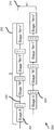
- FIG. 1 illustrates an example of how a frame manager module 100 may process a data packet in a specific order.
- the frame manager module 100 comprises a first buffer manager interface (BMI) stage 102, receiving incoming data from internal memory, operably coupled to Parser stage 104.
- Parser stage 104 parses data, identifies network layers and generates results to be used by subsequent processing stages.
- a further stage 106 steers the processing flow for subsequent stages.
- a frame manager controller stage 108 combines different interfaces with data packet distribution logic to distribute data within the frame manager module 100.
- BMI buffer manager interface
- the frame manager controller stage 108 is operably coupled to policer stage 110, which prioritises and polices data traffic based on various computer algorithms and transmit results to a second BMI 112.
- the second BMI 112 is generally configured to enqueue or drop the transmitted data from the policer stage 1 10.
- a queue manager interface (QMI) 1 14 is operably coupled to second BMI 1 12, and is generally operable to generate frame enqueue requests to a queue manager (not shown).
- a third BMI 1 16 is operably coupled to QMI 1 14, and is operable to release all internal resources from buffers.
- FIG. 1 illustrates a known sequential processing of data packets in a computer network.
- a number of frame manager stages 102-1 16 may dispatch a user-programmable next processing stage (NPS) code, which may be used by the frame manager module's hardware to determine the next stage in the processing pipeline.
- NPS next processing stage
- the frame manager module 100 may allow a user to configure the pipeline stages 102-1 16, thereby allowing each application to perform different functions on the received data packets.
- FIG. 2 illustrates a plurality of processing modules 200, wherein a packet of data is processed in stages 201 in a specific order. These stages 201 effectively form a pipeline 202 that a given packet of data transverses sequentially. As shown, the same stages 201 of the pipeline 202 may be arranged to operate in parallel 203, thereby allowing the processing of multiple data packets at the same time.
- One typical example of the serial/sequential processing of packet data encompasses the steps of: receiving the data packet, parsing the data packet, classifying the data packet, enqueueing the data packet and releasing the data packet.
- NPS registers 204 may allow a user to configure the pipeline stages 201, thereby allowing each application to perform different functions on the data packets. This is referred to as a 'configurable pipeline architecture'.
- the processing module 200 dispatches a user programmable NPS action code 205, which is used by a scheduler (not shown), located in the configurable pipelined architecture in order to determine the next stage to be executed in the pipeline 202 after the current processing stage.
- a scheduler not shown
- the NPS register 204 is the mechanism that allows a user to configure the pipeline 202.
- packet data flows from one stage to the next in a specific order.
- the processing of packet data in such fixed pipeline hardware architecture has been found to be restrictive, particularly when trying to support a very high speed (10-100Gbps) packet processing engine.
- US 7,330,468 B1 proposes a multi-path router, which includes an interface module having a time-sensitive logical processing path and a non-time-sensitive logical processing path and a special needs logical processing path.
- the multi-path router further includes a filter for receiving a packet header and determining the needs of the packet header and for selecting one of the time-sensitive logical processing path, the non-time sensitive logical processing path and the special needs logical processing path in response to the needs of the packet header.
- the multi-path router further includes a router special needs agent (RSNA), adapted to receive a packet header having special needs services.
- RSNA router special needs agent
- the present invention provides a packet processing architecture comprising a plurality of packet processing stages and a method for a packet processing architecture, as described in the accompanying independent patent claims.
- Examples of the invention provide for a packet processing architecture comprising a plurality of packet processing stages, wherein at least one of the packet processing stages comprises multiple next processing stage modules that are operably coupled to respective further processing stages, wherein the multiple next processing stage modules are dynamically configurable.
- examples of the invention provide for a dynamically configurable data packet processing architecture that allows packet data flows from a first stage to any subsequent stage in a user-configurable manner.
- multiple packet processing stages may comprise multiple next processing stage modules.
- at least one of the packet processing stages may be arranged to process a received data packet passing there through and, in response thereto, dynamically configure at least one of the multiple next processing stage modules operably coupled thereto.
- the packet processing stages may be arranged to process the received data packet passing there through to determine a processing stage of the received data packet.
- the at least one of the packet processing stages may be arranged to process the received data packet passing there through to determine content of the received data packet. In some examples, processing the received data packet may comprise performing a stateful examination of the data packet content. In some examples, the at least one of the multiple next processing stage modules may be arranged to feedback a received data packet to one or more previous processing stages. In some examples, the at least one of the multiple next processing stage modules may form a repeat feedback loop between processing stages. In some examples, the dynamic reconfiguration of the plurality of packet processing stages, which may be in a form of a pipeline, may allow bypassing/skipping of one or more packet processing stages, and/or feedback to one or more previous packet processing stages.
- the dynamically configurable data packet processing architecture supports feedback loops, which in some examples may be repeat feedback loops between any of the stages, for example in a very high speed (10-25Gbps) packet processing engine. Repeat feedback loops are advantageous as they allow, among other things, greater flexibility than the known pipeline architecture shown in FIG. 1 and FIG. 2 .
- at least one of the multiple next processing stage modules is arranged to bypass one or more processing stages.
- Examples of the invention also provide a method for a packet processing architecture comprising a plurality of packet processing stages. At least one of the packet processing stages may comprise multiple next processing stage modules. The method comprises dynamically configuring at least one of the next processing stage modules to route a data packet to one of the plurality of data stages.
- FIG. 3 there is illustrated an example of a simplified block diagram of a plurality of processing modules utilising aspects of the invention comprising, a plurality of processing stages 301, 302, 303, 304, each operably coupled to at least one 'next processing stage' (NPS) register 305, forming dynamic reconfigurable pipeline 306.
- NPS 'next processing stage'
- the structure of the NPS may be implemented in any suitable form, for example hardware, firmware, logic, software, etc. or any combination thereof.
- each processing stage 201 comprises a single NPS register 204
- the illustrated example utilises multiple configurable NPS registers 307, 308 per processing stage.
- processing stage 303 comprises two NPS registers 307 and 308, although any number of NPS registers 305 may be implemented into the dynamic reconfigurable pipeline 306. In this example, only one processing stage 303 has a plurality of NPS registers. However, any of processing stages 301, 302, 304 within the dynamic reconfigurable pipeline 306 may also be implemented with any number of NPS registers 305.
- processing stage 303 is operable to dynamically evaluate (at wire-speed), for example from an output of an earlier stage of the pipeline, such as a classifier, e.g. on one example it may be (packet data) traffic dependent, which NPS register (e.g. NPS register 307 or NPS register 308) should be utilised for the next stage of the dynamic reconfigurable pipeline 306.
- a classifier e.g. on one example it may be (packet data) traffic dependent, which NPS register (e.g. NPS register 307 or NPS register 308) should be utilised for the next stage of the dynamic reconfigurable pipeline 306.
- the processing stages 301, 302, 304 may apply a stateful examination of the packet content of data passing there through.
- the processing stage 303 may apply a stateful examination of the packet content of data passing there through, such that the processing of the packet content of the data will determine how the data packet is subsequently processed, for example which of two or more paths may be selected.
- processing stage 303 may decide on the next NPS stage 307, 308 to route the data packet to, by applying one or more criteria to the processed data.
- the decision on the next NPS stage to route the data packet to may be made, based on a processing state of the packet flow. In this illustrated example, dependent upon, say, a stateful examination of the packet content of data passing there through and/or a processing state of the packet flow (e.g.
- processing stage 303 may route the data packet via NPS register 308 and thereafter via feedback loop 309 between processing stage 303 and processing stage 302 within the dynamic reconfigurable pipeline 306.
- one or more feedback loops 309 may be a repeat feedback loop (where the feedback routing of the data packet may be repeated, say, a particular number of times or until a particular processing state of the data packet is achieved).
- processing stage 303 may alternatively or subsequently route the data packet via NPS register 307 and thereafter via processing stage "N+n" 304 within the dynamic reconfigurable pipeline 306.
- one or more of the NPS registers may be used to bypass one or more subsequent processing stages (not shown), dependent upon, say, a stateful examination of the packet content of data passing there through and/or a processing state of the packet flow (e.g. what processing steps have previously been performed).
- NPS register 307 may be utilised, thereby forming an operable connection 310 from processing stage 303 to processing stage 304.
- the pipeline 306 is able to dynamically reconfigure itself in real time since the sequence of the pipeline stages is not pre-wired in hardware (as in known architectures). This is in contrast to the existing known art of software configurability, whereby processing functionality at such processing rates, is provided using fixed pipelines.
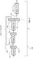
- the dynamically reconfigurable pipeline architecture 400 comprises, frame manager 404 arranged to receive data input 402.
- Frame manager 404 is operably coupled to buffer manager interface (BMI) 406.
- BMI buffer manager interface
- frame manager block 404 is operable to combine different interfaces with packet distribution logic for dynamic distribution of incoming traffic at a line rate of 10-25Gbps, for example, and 'push' this received data into the BMI 406.
- BMI 406 may be operable to store incoming data from the frame manager 404 in internal memory.
- the BMI 406 may be further operable to generate direct memory access (DMA) transactions to store a part of the received data 402 in buffers allocated by the BMI 406.
- DMA direct memory access
- BMI 406 comprises multiple configurable NPS registers 406a, 406b and, in this example is operably coupled to parser module 408 and configured to pass received data thereto.
- the parser module 408 is operable to parse many standard protocols, including options and tunnels, and is operable to support generic configurable capability to allow proprietary or future protocols to be parsed.
- the parser module 408 is operable to parse data and identify network layers, generate results to be used by subsequent processing blocks and configure an NPS register to direct data to a classify module 410.
- Classify module 410 also comprises multiple configurable NPS registers 410a, 410b and, in this example is operable to generate information, and can steer data to either frame manager controller 420 or policer module 412.
- the policer module 412 is operable to prioritize and police data traffic based on, in this example, a two-rate, three-colour marking algorithm. In this way, the policer module 412 is operable to rate-limit traffic to conform to a predetermined rate value.
- the policer module 412 is operable to transmit data to a second BMI module 414.
- a queue manager interface (QMI) 416 is operably coupled to second BMI module 414 and also comprises multiple configurable NPS registers 416a, 416b.
- second BMI module 414 is operable to receive a NPS register value. This register value may cause the second BMI module 414 to either discard data or prepare data to be enqueued. If the result is for data to be enqueued, the second BMI module 414 is operable to copy buffer data from frame manager 404 to external memory (not shown) and invokes the QMI module 416.
- the QMI module 416 is operable to generate a frame enqueue request 415 to a queue manager (not shown).
- a further NPS register value may be generated and used to direct data to third BMI module 418.
- third BMI module 418 releases all internal resources from buffers.
- dynamic reconfigurable pipeline 419 has been configured by at least one NPS register, to enable a repeat loop between the third BMI module 418 and second BMI module 414.
- the number of repeat loops 419 may be dynamically determined by the content or the size of the data being processed.
- the number of loops and the positioning of the dynamic reconfigurable pipeline may be located anywhere within the architecture 400.
- the dynamic reconfigurable pipeline saves DDR bandwidth, which could be utilised instead for reading back data before further processing.
- each block in architecture 400 has at least one NPS register (not shown).
- the at least one NPS register dynamically reconfigures the pipeline at wire speed in order to determine the next stage in the pipeline.
- an effect of the dynamic reconfigurable pipelines is that processor architecture (for example that was not known during a design phase of the architecture) may be implemented after fabrication without physical modification. Due to the utilisation of dynamic reconfigurable pipelines in this example, there is no longer a need to involve software to reconfigure data flow.
- connections as discussed herein may be any type of connection suitable to transfer signals from or to the respective nodes, units or devices, for example via intermediate devices. Accordingly, unless implied or stated otherwise, the connections may for example be direct connections or indirect connections.
- the connections may be illustrated or described in reference to being a single connection, a plurality of connections, unidirectional connections, or bidirectional connections. However, different embodiments may vary the implementation of the connections. For example, separate unidirectional connections may be used rather than bidirectional connections and vice versa.
- plurality of connections may be replaced with a single connection that transfers multiple signals serially or in a time multiplexed manner. Likewise, single connections carrying multiple signals may be separated out into various different connections carrying subsets of these signals. Therefore, many options exist for transferring signals.
- logic blocks are merely illustrative and that alternative embodiments may merge logic blocks or circuit elements or impose an alternate decomposition of functionality upon various logic blocks or circuit elements.
- architectures depicted herein are merely exemplary, and that in fact many other architectures can be implemented which achieve the same functionality.
- any arrangement of components to achieve the same functionality is effectively 'associated' such that the desired functionality is achieved.
- any two components herein combined to achieve a particular functionality can be seen as 'associated with' each other such that the desired functionality is achieved, irrespective of architectures or intermediary components.
- any two components so associated can also be viewed as being 'operably connected,' or 'operably coupled,' to each other to achieve the desired functionality.
- each of the plurality of processing stages may be implemented as circuitry located on a single integrated circuit or within a same device.
- the examples may be implemented as any number of separate integrated circuits or separate devices interconnected with each other in a suitable manner.
- the invention is not limited to physical devices or units implemented in non-programmable hardware but can also be applied in programmable devices or units able to perform the desired device functions by operating in accordance with suitable program code, such as mainframes, minicomputers, servers, workstations, personal computers, notepads, personal digital assistants, electronic games, automotive and other embedded systems, cell phones and various other wireless devices, commonly denoted in this application as 'computer systems'.
- suitable program code such as mainframes, minicomputers, servers, workstations, personal computers, notepads, personal digital assistants, electronic games, automotive and other embedded systems, cell phones and various other wireless devices, commonly denoted in this application as 'computer systems'.
Landscapes
- Engineering & Computer Science (AREA)
- Computer Networks & Wireless Communication (AREA)
- Signal Processing (AREA)
- Computer Security & Cryptography (AREA)
- Logic Circuits (AREA)
Claims (13)
- Architecture (300) de système de traitement de paquets, comprenant une pluralité d'étages de traitement de paquets (301-304), au moins un (303) des étages de traitement de paquets comprenant de multiples registres d'étage de traitement suivant (307, 308) qui sont couplés fonctionnellement à des étages de traitement de paquets supplémentaires respectifs (304, 302), ledit au moins un (303) des étages de traitement de paquets étant conçu pour évaluer dynamiquement lequel des multiples registres d'étage de traitement suivant (307, 308) doit être utilisé, étant conçu en outre pour traiter un paquet de données reçu le traversant afin de déterminer un étage de traitement du paquet de données reçu, et étant conçu en outre encore pour décider des registres d'étage de traitement suivant (307, 308) à utiliser sur la base d'un état de traitement déterminé du flux du paquet de données reçu,
chacun de la pluralité d'étages de traitement de paquets (301-304) étant réalisé avec un nombre quelconque de registres d'étage de traitement suivant (305, 307, 308), chacun de la pluralité d'étages de traitement de paquets (301-304) étant couplé fonctionnellement à au moins un registre d'étage de traitement suivant (305, 307, 308) de manière à former un pipeline reconfigurable dynamiquement (306) d'étages de traitement de paquets (301-304), et
au moins un (307) des registres d'étage de traitement suivant étant utilisable pour former une liaison fonctionnelle (310) avec un autre étage de traitement de paquets (304) de manière à reconfigurer dynamiquement le pipeline (306) en temps réel, la séquence des étages de traitement de paquets en pipeline (301-304) n'étant pas précâblée dans le matériel. - Architecture (400) de système de traitement de paquets selon la revendication 1, dans laquelle de multiples étages de traitement de paquets (406, 410, 416, 418) comprennent de multiples registres d'étage de traitement suivant (406a, 406b, 410a, 410b, 416a, 416b, 418a, 418b).
- Architecture (300 ; 400) de système de traitement de paquets selon la revendication 1 ou la revendication 2, dans laquelle au moins un (303) des étages de traitement de paquets (301-304) est conçu pour traiter un paquet de données reçu le traversant et, en réponse à ce traitement, configurer dynamiquement au moins un des multiples registres d'étage de traitement suivant (307, 308) qui lui est couplé fonctionnellement.
- Architecture (300) de système de traitement de paquets selon la revendication 3, dans laquelle au moins un (303) des étages de traitement de paquets est conçu pour traiter le paquet de données reçu le traversant afin de déterminer un contenu du paquet de données reçu.
- Architecture (300) de système de traitement de paquets selon l'une quelconque des revendications 3 à 4 précédentes, dans laquelle le traitement du paquet de données comprend une inspection à états du contenu du paquet.
- Architecture (300) de système de traitement de paquets selon l'une quelconque des revendications précédentes, dans laquelle au moins un (308) des multiples registres d'étage de traitement suivant (307, 308) est conçu pour réinjecter un paquet de données reçu dans un ou plusieurs étages de traitement de paquets précédents (302).
- Architecture (300) de système de traitement de paquets selon la revendication 6, dans laquelle au moins un (308) des multiples registres d'étage de traitement suivant (307, 308) forme une boucle de réaction à répétition (303, 302) entre des étages de traitement de paquets (303, 302).
- Architecture (300) de système de traitement de paquets selon l'une quelconque des revendications précédentes, dans laquelle au moins un (307) des multiples registres d'étage de traitement suivant (307, 308) est conçu pour contourner un ou plusieurs étages de traitement.
- Procédé pour une architecture (300) de système de traitement de paquets comprenant une pluralité d'étages de traitement de paquets (301-304), au moins un (303) des étages de traitement de paquets (301-304) comprenant de multiples registres d'étage de traitement suivant (307, 308) qui sont couplés fonctionnellement à des étages de traitement de paquets supplémentaires respectifs (304, 302), chacun de la pluralité d'étages de traitement de paquets (301-304) étant couplé fonctionnellement à au moins un registre d'étage de traitement suivant (305, 307, 308) de manière à former un pipeline reconfigurable dynamiquement (306) d'étages de traitement de paquets (301-304), chacun de la pluralité d'étages de traitement de paquets (301-304) étant réalisé avec un nombre quelconque de registres d'étage de traitement suivant (305, 307, 308), et au moins un (307) des registres d'étage de traitement suivant étant utilisable pour former une liaison fonctionnelle (310) avec un autre étage de traitement de paquets (304) de manière à reconfigurer dynamiquement le pipeline (306) en temps réel, la séquence des étages de traitement de paquets en pipeline (301-304) n'étant pas précâblée dans le matériel, et le procédé comprenant les étapes suivantes :ledit au moins un (303) des étages de traitement de paquets (301-304), qui comprend de multiples registres d'étage de traitement suivant (307, 308), évalue dynamiquement lequel des multiples registres d'étage de traitement suivant (307, 308) doit être utilisé,ledit au moins un (303) des étages de traitement de paquets (301-304) traite un paquet de données reçu le traversant, détermine un étage de traitement du paquet de données de reçu, et décide des registres d'étage de traitement suivant (307, 308) à utiliser sur la base d'un état de traitement déterminé du flux du paquet de données reçu.
- Procédé pour une architecture (300) de système de traitement de paquets selon la revendication 9, comprenant en outre le traitement d'un paquet de données reçu traversant au moins un (303) des étages de traitement de paquets (301-304) et, en réponse à ce traitement, la configuration dynamique d'au moins un des multiples registres d'étage de traitement suivant (307, 308) qui lui est couplé fonctionnellement.
- Procédé pour une architecture (300) de système de traitement de paquets selon la revendication 9, dans lequel le traitement du paquet de données reçu traversant comprend la détermination d'un contenu du paquet de données reçu.
- Procédé pour une architecture de système de traitement de paquets selon l'une quelconque des revendications 9 à 11 précédentes, comprenant en outre la réinjection d'un paquet de données reçu dans un ou plusieurs étages de traitement précédents (302).
- Procédé pour une architecture de système de traitement de paquets selon la revendication 12, comprenant en outre la formation d'une boucle de réaction à répétition (303, 302) entre des étages de traitement (303, 302).
Applications Claiming Priority (1)
| Application Number | Priority Date | Filing Date | Title |
|---|---|---|---|
| PCT/IB2013/050219 WO2014108748A1 (fr) | 2013-01-10 | 2013-01-10 | Architecture de traitement de paquet et procédé pour cette architecture |
Publications (3)
| Publication Number | Publication Date |
|---|---|
| EP2943886A1 EP2943886A1 (fr) | 2015-11-18 |
| EP2943886A4 EP2943886A4 (fr) | 2016-12-14 |
| EP2943886B1 true EP2943886B1 (fr) | 2020-03-11 |
Family
ID=51166572
Family Applications (1)
| Application Number | Title | Priority Date | Filing Date |
|---|---|---|---|
| EP13870564.5A Active EP2943886B1 (fr) | 2013-01-10 | 2013-01-10 | Architecture de traitement de paquet et procédé pour cette architecture |
Country Status (3)
| Country | Link |
|---|---|
| US (1) | US10826982B2 (fr) |
| EP (1) | EP2943886B1 (fr) |
| WO (1) | WO2014108748A1 (fr) |
Families Citing this family (6)
| Publication number | Priority date | Publication date | Assignee | Title |
|---|---|---|---|---|
| CN103346980B (zh) * | 2013-07-02 | 2016-08-10 | 华为技术有限公司 | 一种业务调度方法、装置及网络设备 |
| US9722954B2 (en) * | 2013-10-21 | 2017-08-01 | Avago Technologies General Ip (Singapore) Pte. Ltd. | Dynamically tunable heterogeneous latencies in switch or router chips |
| AU2017335771A1 (en) | 2016-09-28 | 2019-02-28 | Musc Foundation For Research Development | Antibodies that bind interleukin-2 and uses thereof |
| WO2019191303A1 (fr) | 2018-03-27 | 2019-10-03 | Arista Networks, Inc. | Système et procédé de reconfiguration sans à-coups d'un pipeline de traitement de données |
| EP3933598A1 (fr) * | 2020-06-30 | 2022-01-05 | Microsoft Technology Licensing, LLC | Pipeline d'apprentissage machine |
| WO2022265736A1 (fr) * | 2021-06-14 | 2022-12-22 | Microsoft Technology Licensing, Llc | Pipeline de traitement de paquets à étages multiples pour une interface de tunnel unique |
Family Cites Families (12)
| Publication number | Priority date | Publication date | Assignee | Title |
|---|---|---|---|---|
| US5835740A (en) | 1992-06-30 | 1998-11-10 | Discovision Associates | Data pipeline system and data encoding method |
| US20030046429A1 (en) * | 2001-08-30 | 2003-03-06 | Sonksen Bradley Stephen | Static data item processing |
| US7512129B1 (en) * | 2002-02-19 | 2009-03-31 | Redback Networks Inc. | Method and apparatus for implementing a switching unit including a bypass path |
| US7330468B1 (en) | 2002-11-18 | 2008-02-12 | At&T Corp. | Scalable, reconfigurable routers |
| US7483374B2 (en) | 2003-08-05 | 2009-01-27 | Scalent Systems, Inc. | Method and apparatus for achieving dynamic capacity and high availability in multi-stage data networks using adaptive flow-based routing |
| FI117033B (fi) * | 2004-02-24 | 2006-05-15 | Valtion Teknillinen | Hajautettu dynaaminen reititys |
| US20070183415A1 (en) * | 2006-02-03 | 2007-08-09 | Utstarcom Incorporated | Method and system for internal data loop back in a high data rate switch |
| US8020168B2 (en) | 2008-05-09 | 2011-09-13 | International Business Machines Corporation | Dynamic virtual software pipelining on a network on chip |
| US8094560B2 (en) * | 2008-05-19 | 2012-01-10 | Cisco Technology, Inc. | Multi-stage multi-core processing of network packets |
| US8619769B2 (en) | 2008-06-12 | 2013-12-31 | Mark Henrik Sandstrom | Packet-layer transparent packet-switching network |
| US8571031B2 (en) * | 2009-10-07 | 2013-10-29 | Intel Corporation | Configurable frame processing pipeline in a packet switch |
| KR20120062174A (ko) | 2010-12-06 | 2012-06-14 | 한국전자통신연구원 | 다양한 특성의 패킷을 동적으로 처리하는 패킷 처리장치 및 방법 |
-
2013
- 2013-01-10 EP EP13870564.5A patent/EP2943886B1/fr active Active
- 2013-01-10 WO PCT/IB2013/050219 patent/WO2014108748A1/fr not_active Ceased
- 2013-01-10 US US14/655,168 patent/US10826982B2/en active Active
Non-Patent Citations (1)
| Title |
|---|
| None * |
Also Published As
| Publication number | Publication date |
|---|---|
| EP2943886A1 (fr) | 2015-11-18 |
| US10826982B2 (en) | 2020-11-03 |
| WO2014108748A1 (fr) | 2014-07-17 |
| EP2943886A4 (fr) | 2016-12-14 |
| US20150341429A1 (en) | 2015-11-26 |
Similar Documents
| Publication | Publication Date | Title |
|---|---|---|
| EP2943886B1 (fr) | Architecture de traitement de paquet et procédé pour cette architecture | |
| US11038993B2 (en) | Flexible processing of network packets | |
| Sun et al. | Fast and flexible: Parallel packet processing with GPUs and click | |
| US20200296058A1 (en) | Heterogeneous Packet-Based Transport | |
| US7895412B1 (en) | Programmable arrayed processing engine architecture for a network switch | |
| US6272621B1 (en) | Synchronization and control system for an arrayed processing engine | |
| US12445395B2 (en) | Network interface device | |
| CN108833299B (zh) | 一种基于可重构交换芯片架构的大规模网络数据处理方法 | |
| US20030099254A1 (en) | Systems and methods for interfacing asynchronous and non-asynchronous data media | |
| EP3503507A1 (fr) | Dispositif d'interface de réseau | |
| US20110010474A1 (en) | Low latency request dispatcher | |
| WO2020197720A1 (fr) | Architecture de commutation de paquets à faible latence | |
| CN106576084A (zh) | 片上数据分组处理系统 | |
| US11294841B1 (en) | Dynamically configurable pipeline | |
| US9083641B2 (en) | Method and apparatus for improving packet processing performance using multiple contexts | |
| US9164771B2 (en) | Method for thread reduction in a multi-thread packet processor | |
| JP2025502043A (ja) | ネットワークインターフェースデバイス | |
| US11509750B2 (en) | Network switching with co-resident data-plane and network interface controllers | |
| JP2005216283A (ja) | シングル・チップ・プロトコル・コンバーター | |
| US9244798B1 (en) | Programmable micro-core processors for packet parsing with packet ordering | |
| Nikologiannis et al. | An FPGA-based queue management system for high speed networking devices | |
| US20230040655A1 (en) | Network switching with co-resident data-plane and network interface controllers | |
| US7551575B1 (en) | Context-switching multi channel programmable stream parser | |
| GB2530513A (en) | Assembling response packets | |
| US8072882B1 (en) | Method and apparatus for a graceful flow control mechanism in a TDM-based packet processing architecture |
Legal Events
| Date | Code | Title | Description |
|---|---|---|---|
| PUAI | Public reference made under article 153(3) epc to a published international application that has entered the european phase |
Free format text: ORIGINAL CODE: 0009012 |
|
| 17P | Request for examination filed |
Effective date: 20150810 |
|
| AK | Designated contracting states |
Kind code of ref document: A1 Designated state(s): AL AT BE BG CH CY CZ DE DK EE ES FI FR GB GR HR HU IE IS IT LI LT LU LV MC MK MT NL NO PL PT RO RS SE SI SK SM TR |
|
| AX | Request for extension of the european patent |
Extension state: BA ME |
|
| DAX | Request for extension of the european patent (deleted) | ||
| REG | Reference to a national code |
Ref country code: DE Ref legal event code: R079 Ref document number: 602013066814 Country of ref document: DE Free format text: PREVIOUS MAIN CLASS: G06F0013140000 Ipc: G06F0015780000 |
|
| A4 | Supplementary search report drawn up and despatched |
Effective date: 20161110 |
|
| RAP1 | Party data changed (applicant data changed or rights of an application transferred) |
Owner name: NXP USA, INC. |
|
| RIC1 | Information provided on ipc code assigned before grant |
Ipc: G06F 15/78 20060101AFI20161104BHEP Ipc: H04L 12/70 20130101ALI20161104BHEP |
|
| STAA | Information on the status of an ep patent application or granted ep patent |
Free format text: STATUS: EXAMINATION IS IN PROGRESS |
|
| 17Q | First examination report despatched |
Effective date: 20170315 |
|
| GRAP | Despatch of communication of intention to grant a patent |
Free format text: ORIGINAL CODE: EPIDOSNIGR1 |
|
| STAA | Information on the status of an ep patent application or granted ep patent |
Free format text: STATUS: GRANT OF PATENT IS INTENDED |
|
| INTG | Intention to grant announced |
Effective date: 20191028 |
|
| GRAS | Grant fee paid |
Free format text: ORIGINAL CODE: EPIDOSNIGR3 |
|
| GRAA | (expected) grant |
Free format text: ORIGINAL CODE: 0009210 |
|
| STAA | Information on the status of an ep patent application or granted ep patent |
Free format text: STATUS: THE PATENT HAS BEEN GRANTED |
|
| AK | Designated contracting states |
Kind code of ref document: B1 Designated state(s): AL AT BE BG CH CY CZ DE DK EE ES FI FR GB GR HR HU IE IS IT LI LT LU LV MC MK MT NL NO PL PT RO RS SE SI SK SM TR |
|
| REG | Reference to a national code |
Ref country code: GB Ref legal event code: FG4D |
|
| REG | Reference to a national code |
Ref country code: CH Ref legal event code: EP |
|
| REG | Reference to a national code |
Ref country code: AT Ref legal event code: REF Ref document number: 1244033 Country of ref document: AT Kind code of ref document: T Effective date: 20200315 |
|
| REG | Reference to a national code |
Ref country code: IE Ref legal event code: FG4D |
|
| REG | Reference to a national code |
Ref country code: DE Ref legal event code: R096 Ref document number: 602013066814 Country of ref document: DE |
|
| PG25 | Lapsed in a contracting state [announced via postgrant information from national office to epo] |
Ref country code: RS Free format text: LAPSE BECAUSE OF FAILURE TO SUBMIT A TRANSLATION OF THE DESCRIPTION OR TO PAY THE FEE WITHIN THE PRESCRIBED TIME-LIMIT Effective date: 20200311 Ref country code: FI Free format text: LAPSE BECAUSE OF FAILURE TO SUBMIT A TRANSLATION OF THE DESCRIPTION OR TO PAY THE FEE WITHIN THE PRESCRIBED TIME-LIMIT Effective date: 20200311 Ref country code: NO Free format text: LAPSE BECAUSE OF FAILURE TO SUBMIT A TRANSLATION OF THE DESCRIPTION OR TO PAY THE FEE WITHIN THE PRESCRIBED TIME-LIMIT Effective date: 20200611 |
|
| REG | Reference to a national code |
Ref country code: NL Ref legal event code: MP Effective date: 20200311 |
|
| PG25 | Lapsed in a contracting state [announced via postgrant information from national office to epo] |
Ref country code: LV Free format text: LAPSE BECAUSE OF FAILURE TO SUBMIT A TRANSLATION OF THE DESCRIPTION OR TO PAY THE FEE WITHIN THE PRESCRIBED TIME-LIMIT Effective date: 20200311 Ref country code: GR Free format text: LAPSE BECAUSE OF FAILURE TO SUBMIT A TRANSLATION OF THE DESCRIPTION OR TO PAY THE FEE WITHIN THE PRESCRIBED TIME-LIMIT Effective date: 20200612 Ref country code: HR Free format text: LAPSE BECAUSE OF FAILURE TO SUBMIT A TRANSLATION OF THE DESCRIPTION OR TO PAY THE FEE WITHIN THE PRESCRIBED TIME-LIMIT Effective date: 20200311 Ref country code: SE Free format text: LAPSE BECAUSE OF FAILURE TO SUBMIT A TRANSLATION OF THE DESCRIPTION OR TO PAY THE FEE WITHIN THE PRESCRIBED TIME-LIMIT Effective date: 20200311 Ref country code: BG Free format text: LAPSE BECAUSE OF FAILURE TO SUBMIT A TRANSLATION OF THE DESCRIPTION OR TO PAY THE FEE WITHIN THE PRESCRIBED TIME-LIMIT Effective date: 20200611 |
|
| REG | Reference to a national code |
Ref country code: LT Ref legal event code: MG4D |
|
| PG25 | Lapsed in a contracting state [announced via postgrant information from national office to epo] |
Ref country code: NL Free format text: LAPSE BECAUSE OF FAILURE TO SUBMIT A TRANSLATION OF THE DESCRIPTION OR TO PAY THE FEE WITHIN THE PRESCRIBED TIME-LIMIT Effective date: 20200311 |
|
| PG25 | Lapsed in a contracting state [announced via postgrant information from national office to epo] |
Ref country code: RO Free format text: LAPSE BECAUSE OF FAILURE TO SUBMIT A TRANSLATION OF THE DESCRIPTION OR TO PAY THE FEE WITHIN THE PRESCRIBED TIME-LIMIT Effective date: 20200311 Ref country code: SK Free format text: LAPSE BECAUSE OF FAILURE TO SUBMIT A TRANSLATION OF THE DESCRIPTION OR TO PAY THE FEE WITHIN THE PRESCRIBED TIME-LIMIT Effective date: 20200311 Ref country code: LT Free format text: LAPSE BECAUSE OF FAILURE TO SUBMIT A TRANSLATION OF THE DESCRIPTION OR TO PAY THE FEE WITHIN THE PRESCRIBED TIME-LIMIT Effective date: 20200311 Ref country code: SM Free format text: LAPSE BECAUSE OF FAILURE TO SUBMIT A TRANSLATION OF THE DESCRIPTION OR TO PAY THE FEE WITHIN THE PRESCRIBED TIME-LIMIT Effective date: 20200311 Ref country code: EE Free format text: LAPSE BECAUSE OF FAILURE TO SUBMIT A TRANSLATION OF THE DESCRIPTION OR TO PAY THE FEE WITHIN THE PRESCRIBED TIME-LIMIT Effective date: 20200311 Ref country code: IS Free format text: LAPSE BECAUSE OF FAILURE TO SUBMIT A TRANSLATION OF THE DESCRIPTION OR TO PAY THE FEE WITHIN THE PRESCRIBED TIME-LIMIT Effective date: 20200711 Ref country code: CZ Free format text: LAPSE BECAUSE OF FAILURE TO SUBMIT A TRANSLATION OF THE DESCRIPTION OR TO PAY THE FEE WITHIN THE PRESCRIBED TIME-LIMIT Effective date: 20200311 Ref country code: PT Free format text: LAPSE BECAUSE OF FAILURE TO SUBMIT A TRANSLATION OF THE DESCRIPTION OR TO PAY THE FEE WITHIN THE PRESCRIBED TIME-LIMIT Effective date: 20200805 |
|
| REG | Reference to a national code |
Ref country code: AT Ref legal event code: MK05 Ref document number: 1244033 Country of ref document: AT Kind code of ref document: T Effective date: 20200311 |
|
| REG | Reference to a national code |
Ref country code: DE Ref legal event code: R097 Ref document number: 602013066814 Country of ref document: DE |
|
| PLBE | No opposition filed within time limit |
Free format text: ORIGINAL CODE: 0009261 |
|
| STAA | Information on the status of an ep patent application or granted ep patent |
Free format text: STATUS: NO OPPOSITION FILED WITHIN TIME LIMIT |
|
| PG25 | Lapsed in a contracting state [announced via postgrant information from national office to epo] |
Ref country code: ES Free format text: LAPSE BECAUSE OF FAILURE TO SUBMIT A TRANSLATION OF THE DESCRIPTION OR TO PAY THE FEE WITHIN THE PRESCRIBED TIME-LIMIT Effective date: 20200311 Ref country code: IT Free format text: LAPSE BECAUSE OF FAILURE TO SUBMIT A TRANSLATION OF THE DESCRIPTION OR TO PAY THE FEE WITHIN THE PRESCRIBED TIME-LIMIT Effective date: 20200311 Ref country code: AT Free format text: LAPSE BECAUSE OF FAILURE TO SUBMIT A TRANSLATION OF THE DESCRIPTION OR TO PAY THE FEE WITHIN THE PRESCRIBED TIME-LIMIT Effective date: 20200311 Ref country code: DK Free format text: LAPSE BECAUSE OF FAILURE TO SUBMIT A TRANSLATION OF THE DESCRIPTION OR TO PAY THE FEE WITHIN THE PRESCRIBED TIME-LIMIT Effective date: 20200311 |
|
| 26N | No opposition filed |
Effective date: 20201214 |
|
| PG25 | Lapsed in a contracting state [announced via postgrant information from national office to epo] |
Ref country code: SI Free format text: LAPSE BECAUSE OF FAILURE TO SUBMIT A TRANSLATION OF THE DESCRIPTION OR TO PAY THE FEE WITHIN THE PRESCRIBED TIME-LIMIT Effective date: 20200311 Ref country code: PL Free format text: LAPSE BECAUSE OF FAILURE TO SUBMIT A TRANSLATION OF THE DESCRIPTION OR TO PAY THE FEE WITHIN THE PRESCRIBED TIME-LIMIT Effective date: 20200311 |
|
| PG25 | Lapsed in a contracting state [announced via postgrant information from national office to epo] |
Ref country code: MC Free format text: LAPSE BECAUSE OF FAILURE TO SUBMIT A TRANSLATION OF THE DESCRIPTION OR TO PAY THE FEE WITHIN THE PRESCRIBED TIME-LIMIT Effective date: 20200311 |
|
| REG | Reference to a national code |
Ref country code: CH Ref legal event code: PL |
|
| GBPC | Gb: european patent ceased through non-payment of renewal fee |
Effective date: 20210110 |
|
| PG25 | Lapsed in a contracting state [announced via postgrant information from national office to epo] |
Ref country code: LU Free format text: LAPSE BECAUSE OF NON-PAYMENT OF DUE FEES Effective date: 20210110 |
|
| REG | Reference to a national code |
Ref country code: BE Ref legal event code: MM Effective date: 20210131 |
|
| PG25 | Lapsed in a contracting state [announced via postgrant information from national office to epo] |
Ref country code: FR Free format text: LAPSE BECAUSE OF NON-PAYMENT OF DUE FEES Effective date: 20210131 |
|
| PG25 | Lapsed in a contracting state [announced via postgrant information from national office to epo] |
Ref country code: LI Free format text: LAPSE BECAUSE OF NON-PAYMENT OF DUE FEES Effective date: 20210131 Ref country code: GB Free format text: LAPSE BECAUSE OF NON-PAYMENT OF DUE FEES Effective date: 20210110 Ref country code: CH Free format text: LAPSE BECAUSE OF NON-PAYMENT OF DUE FEES Effective date: 20210131 |
|
| PG25 | Lapsed in a contracting state [announced via postgrant information from national office to epo] |
Ref country code: IE Free format text: LAPSE BECAUSE OF NON-PAYMENT OF DUE FEES Effective date: 20210110 |
|
| PG25 | Lapsed in a contracting state [announced via postgrant information from national office to epo] |
Ref country code: BE Free format text: LAPSE BECAUSE OF NON-PAYMENT OF DUE FEES Effective date: 20210131 |
|
| PG25 | Lapsed in a contracting state [announced via postgrant information from national office to epo] |
Ref country code: HU Free format text: LAPSE BECAUSE OF FAILURE TO SUBMIT A TRANSLATION OF THE DESCRIPTION OR TO PAY THE FEE WITHIN THE PRESCRIBED TIME-LIMIT; INVALID AB INITIO Effective date: 20130110 |
|
| PGFP | Annual fee paid to national office [announced via postgrant information from national office to epo] |
Ref country code: DE Payment date: 20221220 Year of fee payment: 11 |
|
| PG25 | Lapsed in a contracting state [announced via postgrant information from national office to epo] |
Ref country code: CY Free format text: LAPSE BECAUSE OF FAILURE TO SUBMIT A TRANSLATION OF THE DESCRIPTION OR TO PAY THE FEE WITHIN THE PRESCRIBED TIME-LIMIT Effective date: 20200311 |
|
| P01 | Opt-out of the competence of the unified patent court (upc) registered |
Effective date: 20230725 |
|
| PG25 | Lapsed in a contracting state [announced via postgrant information from national office to epo] |
Ref country code: MK Free format text: LAPSE BECAUSE OF FAILURE TO SUBMIT A TRANSLATION OF THE DESCRIPTION OR TO PAY THE FEE WITHIN THE PRESCRIBED TIME-LIMIT Effective date: 20200311 |
|
| REG | Reference to a national code |
Ref country code: DE Ref legal event code: R119 Ref document number: 602013066814 Country of ref document: DE |
|
| PG25 | Lapsed in a contracting state [announced via postgrant information from national office to epo] |
Ref country code: MT Free format text: LAPSE BECAUSE OF FAILURE TO SUBMIT A TRANSLATION OF THE DESCRIPTION OR TO PAY THE FEE WITHIN THE PRESCRIBED TIME-LIMIT Effective date: 20200311 |
|
| PG25 | Lapsed in a contracting state [announced via postgrant information from national office to epo] |
Ref country code: DE Free format text: LAPSE BECAUSE OF NON-PAYMENT OF DUE FEES Effective date: 20240801 |
|
| PG25 | Lapsed in a contracting state [announced via postgrant information from national office to epo] |
Ref country code: DE Free format text: LAPSE BECAUSE OF NON-PAYMENT OF DUE FEES Effective date: 20240801 |
|
| PG25 | Lapsed in a contracting state [announced via postgrant information from national office to epo] |
Ref country code: TR Free format text: LAPSE BECAUSE OF FAILURE TO SUBMIT A TRANSLATION OF THE DESCRIPTION OR TO PAY THE FEE WITHIN THE PRESCRIBED TIME-LIMIT Effective date: 20200311 |