EP2944006B1 - Turbinenbasiertes energieerzeugungssystem mit gleichstromausgang - Google Patents
Turbinenbasiertes energieerzeugungssystem mit gleichstromausgang Download PDFInfo
- Publication number
- EP2944006B1 EP2944006B1 EP14701136.5A EP14701136A EP2944006B1 EP 2944006 B1 EP2944006 B1 EP 2944006B1 EP 14701136 A EP14701136 A EP 14701136A EP 2944006 B1 EP2944006 B1 EP 2944006B1
- Authority
- EP
- European Patent Office
- Prior art keywords
- energy
- converter
- electrical energy
- operable
- sub
- Prior art date
- Legal status (The legal status is an assumption and is not a legal conclusion. Google has not performed a legal analysis and makes no representation as to the accuracy of the status listed.)
- Active
Links
Images





Classifications
-
- H—ELECTRICITY
- H02—GENERATION; CONVERSION OR DISTRIBUTION OF ELECTRIC POWER
- H02J—ELECTRIC POWER NETWORKS; CIRCUIT ARRANGEMENTS OR SYSTEMS FOR SUPPLYING OR DISTRIBUTING ELECTRIC POWER; SYSTEMS FOR STORING ELECTRIC ENERGY
- H02J3/00—Circuit arrangements for AC mains or AC distribution networks
- H02J3/36—Arrangements for transfer of electric power between AC networks via high-voltage DC [HVDC] links; Arrangements for transfer of electric power between generators and networks via HVDC links
-
- H—ELECTRICITY
- H02—GENERATION; CONVERSION OR DISTRIBUTION OF ELECTRIC POWER
- H02J—ELECTRIC POWER NETWORKS; CIRCUIT ARRANGEMENTS OR SYSTEMS FOR SUPPLYING OR DISTRIBUTING ELECTRIC POWER; SYSTEMS FOR STORING ELECTRIC ENERGY
- H02J3/00—Circuit arrangements for AC mains or AC distribution networks
- H02J3/38—Arrangements for feeding a single network from two or more generators or sources in parallel; Arrangements for feeding already energised networks from additional generators or sources in parallel
- H02J3/381—Dispersed generators
-
- H—ELECTRICITY
- H02—GENERATION; CONVERSION OR DISTRIBUTION OF ELECTRIC POWER
- H02K—DYNAMO-ELECTRIC MACHINES
- H02K47/00—Dynamo-electric converters
- H02K47/02—AC/DC converters or vice versa
-
- H—ELECTRICITY
- H02—GENERATION; CONVERSION OR DISTRIBUTION OF ELECTRIC POWER
- H02M—APPARATUS FOR CONVERSION BETWEEN AC AND AC, BETWEEN AC AND DC, OR BETWEEN DC AND DC, AND FOR USE WITH MAINS OR SIMILAR POWER SUPPLY SYSTEMS; CONVERSION OF DC OR AC INPUT POWER INTO SURGE OUTPUT POWER; CONTROL OR REGULATION THEREOF
- H02M7/00—Conversion of AC power input into DC power output; Conversion of DC power input into AC power output
- H02M7/42—Conversion of DC power input into AC power output without possibility of reversal
- H02M7/44—Conversion of DC power input into AC power output without possibility of reversal by static converters
- H02M7/48—Conversion of DC power input into AC power output without possibility of reversal by static converters using discharge tubes with control electrode or semiconductor devices with control electrode
- H02M7/483—Converters with outputs that each can have more than two voltages levels
-
- H—ELECTRICITY
- H02—GENERATION; CONVERSION OR DISTRIBUTION OF ELECTRIC POWER
- H02M—APPARATUS FOR CONVERSION BETWEEN AC AND AC, BETWEEN AC AND DC, OR BETWEEN DC AND DC, AND FOR USE WITH MAINS OR SIMILAR POWER SUPPLY SYSTEMS; CONVERSION OF DC OR AC INPUT POWER INTO SURGE OUTPUT POWER; CONTROL OR REGULATION THEREOF
- H02M7/00—Conversion of AC power input into DC power output; Conversion of DC power input into AC power output
- H02M7/42—Conversion of DC power input into AC power output without possibility of reversal
- H02M7/44—Conversion of DC power input into AC power output without possibility of reversal by static converters
- H02M7/48—Conversion of DC power input into AC power output without possibility of reversal by static converters using discharge tubes with control electrode or semiconductor devices with control electrode
- H02M7/483—Converters with outputs that each can have more than two voltages levels
- H02M7/4835—Converters with outputs that each can have more than two voltages levels comprising two or more cells, each including a switchable capacitor, the capacitors having a nominal charge voltage which corresponds to a given fraction of the input voltage, and the capacitors being selectively connected in series to determine the instantaneous output voltage
-
- H—ELECTRICITY
- H02—GENERATION; CONVERSION OR DISTRIBUTION OF ELECTRIC POWER
- H02J—ELECTRIC POWER NETWORKS; CIRCUIT ARRANGEMENTS OR SYSTEMS FOR SUPPLYING OR DISTRIBUTING ELECTRIC POWER; SYSTEMS FOR STORING ELECTRIC ENERGY
- H02J2101/00—Supply or distribution of decentralised, dispersed or local electric power generation
- H02J2101/20—Dispersed power generation using renewable energy sources
- H02J2101/28—Wind energy
-
- Y—GENERAL TAGGING OF NEW TECHNOLOGICAL DEVELOPMENTS; GENERAL TAGGING OF CROSS-SECTIONAL TECHNOLOGIES SPANNING OVER SEVERAL SECTIONS OF THE IPC; TECHNICAL SUBJECTS COVERED BY FORMER USPC CROSS-REFERENCE ART COLLECTIONS [XRACs] AND DIGESTS
- Y02—TECHNOLOGIES OR APPLICATIONS FOR MITIGATION OR ADAPTATION AGAINST CLIMATE CHANGE
- Y02E—REDUCTION OF GREENHOUSE GAS [GHG] EMISSIONS, RELATED TO ENERGY GENERATION, TRANSMISSION OR DISTRIBUTION
- Y02E10/00—Energy generation through renewable energy sources
- Y02E10/70—Wind energy
- Y02E10/76—Power conversion electric or electronic aspects
-
- Y—GENERAL TAGGING OF NEW TECHNOLOGICAL DEVELOPMENTS; GENERAL TAGGING OF CROSS-SECTIONAL TECHNOLOGIES SPANNING OVER SEVERAL SECTIONS OF THE IPC; TECHNICAL SUBJECTS COVERED BY FORMER USPC CROSS-REFERENCE ART COLLECTIONS [XRACs] AND DIGESTS
- Y02—TECHNOLOGIES OR APPLICATIONS FOR MITIGATION OR ADAPTATION AGAINST CLIMATE CHANGE
- Y02E—REDUCTION OF GREENHOUSE GAS [GHG] EMISSIONS, RELATED TO ENERGY GENERATION, TRANSMISSION OR DISTRIBUTION
- Y02E60/00—Enabling technologies; Technologies with a potential or indirect contribution to GHG emissions mitigation
- Y02E60/60—Arrangements for transfer of electric power between AC networks or generators via a high voltage DC link [HVCD]
Definitions
- the instant application relates to turbine-based energy generation systems, and more particularly to turbine-based energy generation systems having a DC output.
- Energy from a turbine is converted into a form suitable for collection of energy from multiple turbines. This is preferably done cost-effectively, safely, and with few system failures.
- US20110049994A1 describes a wind farm with DC collection, in which the power conversion chain in the tower includes a generator and a modular multi-level (MMC) rectifier with unipolar modules.
- US8174138B2 and WO2011055175A1 describe a wind generator-rectifier setup with rectifier modules stacked on the DC side.
- US20100133901A1 describes a power delivery system with identical stacked modular converters at either end of a DC transmission line.
- US8018083B2 describes a wind generator-rectifier setup with a matrix converter, step-up transformer and rectifier feeding a high voltage DC collection grid.
- US7324359B2 describes a wind generator-rectifier setup with a multi-winding step-up transformer feeding two-level rectifier modules stacked on the DC side.
- WO2012041380A1 describes an MMC rectifier with both unipolar modules which produce unipolar voltages and bipolar modules which produce bipolar voltages, for enabling fault handling capabilities.
- WO2012048743A1 describes cluster platform based solutions with a reduced number of components in the wind tower.
- EP2408081 describes a modular multi-level converter with both unipolar and bipolar converter cells.
- a turbine-based energy generation system includes an electric generator for converting mechanical energy from a turbine into AC electrical energy and a converter for converting the AC electrical energy to DC electrical energy.
- a step-up transformer is provided between the generator and the converter. The step-up transformer increases the DC output voltage of the system, provides high voltage isolation to the generator, and enables more efficient energy collection.
- the invention is defined by an energy generation system according to independent claim 1 and a method of generating electrical energy according to independent claim 15. Another embodiment of the invention is defined by an energy generation system according to independent claim 16.
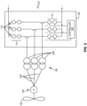
- Figure 1 illustrates an embodiment of a turbine-based energy generation system which includes an electric generator (G) 100 for converting mechanical energy from a turbine 102 into AC electrical energy, and a converter 104 for converting the AC electrical energy to DC electrical energy at the system output (+/- DC OUT ).
- the turbine 102 extracts energy from a fluid flow such as air or other gas, or water or other liquid.
- the turbine 102 can be a wind, wave, or tidal turbine which converts the extracted energy into mechanical energy.
- the generator output is typically between about 3.3kV and 13.8kV, but other ranges are within the scope of the embodiments described herein. Tangential components of the system which are not germane to the invention are excluded from Figure 1 for ease of illustration, such as AC breakers, control devices, monitoring equipment, etc.
- a step-up transformer 106 is provided between the generator 100 and the converter 104 to increase the DC output voltage of the system and enable more efficient energy collection.
- the step-up transformer 106 transfers the AC electrical energy at a lower voltage from the electric generator 100 to a higher voltage toward the converter 104.
- the step-up transformer 106 transfers the AC electrical energy from the electric generator 100 to at least 10 kV e.g. to at least 25 kV, 60 kV or even higher.
- the addition of the step-up transformer 106 permits a wind tower to output higher DC output voltage as compared to conventional wind towers. Doing so enables more efficient collection and transmission over longer distances without any need for an additional substation/platform. If the nominal frequency of the generator 100 is greater than 60 Hz, a smaller step-up transformer 106 can be used which makes installation easier in wind tower applications.
- the step-up transformer 106 is an autotransformer.
- the converter 104 converts the AC electrical energy at the higher voltage from the step-up transformer 106 to DC electrical energy. Operation of the converter is managed by a controller 108.
- the converter 104 is a modular multi-level converter (MMC).
- MMC modular multi-level converter
- the use of an MMC 104 yields a lower-cost system as compared to conventional solutions, while maintaining high controllability of the generator output.
- An MMC 104 permits scalable output voltage, a variety of installation and arrangement options, and/or improved fault handling characteristics. For example in a wind tower application, the turbine-based energy generation system with DC output uses fewer conversion stages in the tower as compared to a tower with AC output. This in turn lowers the overall system cost as compared to a wind farm with AC collection.
- a converter leg 110 is provided for each phase of the AC electrical energy.
- the converter legs 110 of the MMC 104 each have an upper arm with a first plurality of sub-modules 112 and a lower arm with a second plurality of sub-modules 114.
- the sub-modules 112, 114 comprise switching cells such as power semiconductor transistors and an energy storage device such as a DC capacitor, a thyristor bypass device, auxiliary units such as gate drivers, etc.
- Each sub-module 112, 114 functions as a controlled voltage source.
- the sub-modules 112, 114 can comprise unipolar or bipolar cells, where each cell is a two-terminal arrangement of semiconductor switches and energy storage element(s). Unipolar cells produce unipolar voltages, and bipolar cells produce bipolar voltages.
- FIG. 2 shows an embodiment of a unipolar cell included in an individual sub-module 112/114 of the MMC 104.
- the unipolar cell includes a pair of power transistors T1, T2 connected in a half-bridge configuration, in parallel with a DC capacitor C DC .
- Each power transistor T1, T2 is coupled in parallel with a corresponding freewheeling diode D1, D2.
- FIG. 3 shows an embodiment of a bipolar cell included in an individual sub-module 112/114 of the MMC 104.
- the bipolar cell includes two pairs of power transistors T3, T4 and T5, T6 connected in a full-bridge configuration, in parallel with a DC capacitor C DC .
- Each power transistor T3, T4, T5, T6 is coupled in parallel with a corresponding freewheeling diode D3, D4, D5, D6.
- both unipolar and bipolar cells can be used in the converter 104.
- the sub-modules 112/114 with bipolar cells can reduce the voltage of the DC electrical energy output by the system by reversing their DC output polarity responsive to a detected DC fault or voltage collapse condition (i.e. an error condition). Doing so limits the DC fault current.
- the converter controller 108 can shut down all of the sub-modules 112, 114 or short-circuit all of the sub-modules 112, 114 responsive to an error condition.
- the controller 108 can shut down or short circuit the converter sub-modules 112, 114 by turning off the gate signals to the sub-module cells.
- Various error conditions can cause the controller 108 to take this corrective action, e.g. such as short circuits, DC/AC current exceeding a maximum value, overvoltage, the system voltage falls below either a fixed value or a converter operation point dependent value, etc.
- the controller 108 can detect the error condition or receive error information from an external detector or another controller.
- the turbine-based energy generation system described herein can be deployed in various applications with different configurations.
- the turbine-based energy generation system can be used in wind, wave, or tidal power generation applications.
- FIG. 4 illustrates an embodiment of the turbine-based energy generation system deployed in a wind tower application.
- a group (farm) of wind towers is provided.
- a turbine-based energy generation system as described herein is associated with each individual wind tower.
- the components of a single wind tower-based system are shown in Figure 4 for ease of illustration. Some of the system components are collocated in the physical tower (represented by the text label ⁇ in tower' in Figure 4 ) and other components are disposed outside the tower e.g. on an offshore (cluster) platform (represented by the text label 'on cluster platform' in Figure 4 ), forming a virtual wind tower farm with a DC output (DC OUT ).
- at least a rotor i.e.
- each turbine 102 and the corresponding electric generator 100 are housed in a nacelle of the physical wind tower structure, and the converters 104 are located outside the nacelle.
- the rotor for a typical utility-scale wind turbine includes three high-tech blades, a hub, and a spinner.
- the nacelle of a wind turbine is the box-like component that sits atop the tower and is connected to the rotor.
- the nacelle and generator 100 are mounted on top of a high tower to allow the rotor blades to take advantage of the best winds.
- the rotor, nacelle, and physical tower structure are not shown in Figure 4 for ease of illustration. These components of a wind tower are well known to those skilled in the art, and therefore no further description or illustration is provided.
- the wind tower system is located off-shore.
- the converters can be located on an offshore platform.
- the converters instead can be located in the respective towers or elsewhere depending on the specific wind tower application.
- the step-up transformers 106 can be in the same physical wind tower structure as the corresponding turbine 102 and electric generator 100 or in a different structure.
- a separate step-up transformer 106 and a separate converter 104 are provided for each wind tower in the farm (the other wind towers are represented by the text label 'other tower' in Figure 4 ).
- a separate step-up transformer 106 can be provided for each wind tower in the farm and a single converter 104 can be used to convert the AC electrical energy at the higher voltage from all of the step-up transformers 106 to DC electrical energy.
- a single step-up transformer 106 is provided for transferring the AC electrical energy at a lower voltage from all of the electric generators 100 to a higher voltage and a single converter 104 is provided for converting the AC electrical energy at the higher voltage from the single step-up transformer 106 to DC electrical energy.
- the step-up transformer 106 used in the turbine-based energy generation system can be a single multi-phase transformer e.g. with three phases as shown in Figure 1 .
- FIG. 5 illustrates another embodiment of the step-up transformer 106, implemented as a plurality of cores 200 each one of which is coupled to a different phase 202 of the electric generator 100.
- Each leg 110 of the converter 104 is connected to a different core 200 of the step-up transformer 106.
- the cores 200 of the step-up transformer 106 can be vertically spaced apart from one other e.g. located on different floors of a wind tower or other structure.
- Each leg 110 of the converter 104 can be located on the same floor of the wind tower structure as the transformer core 200 to which that converter leg 110 is coupled.
- the parts of each phase of the turbine-based energy generation system can be housed together and the phases located on separate floors in a wind tower or other structure.
- FIG 6 illustrates another embodiment of the turbine-based energy generation system.
- a multi-winding step-up transformer 106 is used (three phases are shown in Figure 5 ).
- the multi-winding step-up transformer 106 transfers AC electrical energy at a lower voltage from the electric generator 100 on one side to a higher voltage toward the converter 104 on the other side, as previously described herein.
- the converter 104 includes MMC-based rectifier subsystems 300 in cascade. Using MMC-based rectifiers 300 reduces system cost while maintaining high controllability of the generator output, as previously described herein.
- inventions illustrated in Figures 1-6 are applicable to any turbine-based generation source (e.g. wind, tidal, etc.), can use unipolar and/or bipolar cells in the same converter, can use a multi-winding step-transformer with series-connected rectifiers at the transformer output, can permit different physical location of components within a wind tower or other structure, and/or can use an autotransformer as previously described herein.
- any turbine-based generation source e.g. wind, tidal, etc.
- wind towers with a DC output may have protection actions such as opening or shorting of the converter sub-modules, connection of multiple generators to a single transformer and converter, multiple turbines having a point-of-common-coupling either on the DC or AC side of an inverter, and/or series and parallel connections of windmills.
- medium voltage (MV) collection wind parks can provide connection of multiple converters to a medium voltage bus. In this case, the wind mill generators are isolated from the DC bus by the step-up transformer(s), limiting short circuit currents.
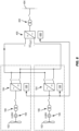
- FIG. 7 illustrates an embodiment of a MV power collection wind park which employs the turbine-based energy generation system described herein and has MV DC power collection.
- the MV power collection wind park includes a plurality of turbines 102 each for extracting energy from a fluid flow and converting the extracted energy into mechanical energy, a plurality of electric generators 100 each for converting the mechanical energy from one of the turbines into AC electrical energy, and a plurality of step-up transformers 106 each for transferring the AC electrical energy at a lower voltage from one of the electric generators 100 to a higher voltage.
- the step-up transformers 106 also isolate the generators 100 from the high voltage part of the MV power collection wind park.
- the MV power collection wind park also includes a plurality of converters 104 each for converting the AC electrical energy at the higher voltage from one of the step-up transformers 106 to DC electrical energy.
- Each converter 104 includes a converter leg 110 for each phase of the AC electrical energy coupled to that converter 104.
- Each converter leg 110 has an upper arm with a first plurality of sub-modules and a lower arm with a second plurality of sub-modules, each sub-module functioning as a controlled voltage source as previously described herein.
- the converter sub-modules are not shown in Figure 7 for ease of illustration.
- Each generator 100 is a low voltage (LV) or medium voltage (MV) generator which generates e.g. 5-10 MW of power.
- the step-up transformers 106 provide high voltage isolation for the generators 100, and increase the voltage from the generators 100.
- the converters 104 are connected in series, yielding a high voltage DC output.
- An inverter 400 can be provided at the DC output (DC OUT ) of the MV power collection wind park for converting the DC output to AC.
- the inverter 400 can be an MMC or other type of inverter.
- a transformer 402 couples the AC energy from the inverter 400 e.g. to an AC grid or other power transmission system 404.
- a separate controller 108/406 can be provided for each converter 104 and inverter 400, for controlling individual operation of the converters 104 and inverter 400.
- the controllers 108, 406 can coordinate between each other, or a master controller can be provided for coordinating operation.
- Figure 8 illustrates another embodiment of a MV power collection wind park.
- the embodiment shown in Figure 8 is similar to the one shown in Figure 7 , however the converters 104 are connected in parallel instead of in series.
- Figure 9 illustrates yet another embodiment of a MV power collection wind park.
- the embodiment shown in Figure 9 is similar to the one shown in Figure 7 , however a first group 500 of the converters 104 is connected in series and a second group 502 of the converters 104 is connected in parallel with the first group 500.
- the turbine-based energy generation systems including the second group 502 of converters 104 are represented by a single dashed box in Figure 9 for ease of illustration, but have the same or similar construction as the turbine-based energy generation systems including the first group 500 of converters 104 connected in series which are shown in Figure 9 .
- One or more of the converters 104 shown in Figure 7-9 can be an MMC as previously described herein.
Landscapes
- Engineering & Computer Science (AREA)
- Power Engineering (AREA)
- Control Of Eletrric Generators (AREA)
Claims (16)
- Energieerzeugungssystem, umfassend:eine Turbine (102), die dazu geeignet ist, aus einem Fluidstrom Energie zu gewinnen und die gewonnene Energie in mechanische Energie umzuwandeln;einen Elektrogenerator (100), der dazu geeignet ist, die mechanische Energie von der Turbine (102) in elektrischen Wechselstrom umzuwandeln;einen Aufspanntransformator (106), der dazu geeignet ist, den elektrischen Wechselstrom mit einer niedrigeren Spannung, von dem Elektrogenerator (100), auf eine höhere Spannung heraufzusetzen; undeinen Wandler (104), der dazu geeignet ist, den elektrischen Wechselstrom mit der höheren Spannung in elektrischen Gleichstrom umzuwandeln, wobei der Wandler (104) einen Wandlerzweig (110) für eine Phase des elektrischen Wechselstroms umfasst, wobei der Wandlerzweig (110) einen oberen Strang mit einer ersten Vielzahl von Untermodulen (112) und einem unteren Strang mit einer zweiten Vielzahl von Untermodulen (114) aufweist, wobei ein oder mehrere Untermodule (112, 114), vorzugsweise jedes Untermodul (112, 114), eine bipolare Zelle umfassen, beinhaltend:einen Gleichstromkondensator (Coe),zwei Paar Leistungstransistoren (T3, T4 und T5, T6), die in einer Vollbrückenkonfiguration parallel zum Gleichstromkondensator (Coe) geschaltet sind, undvier Freilaufdioden (D3, D4, D5, D6), wobei jede Diode (D3, D4, D5, D6) jedem Leistungstransistor (T3, T4, T5, T6) entspricht und mit diesem parallel geschaltet ist,wobei jedes Untermodul (112, 114) dazu geeignet ist, als geregelte Spannungsquelle zu funktionieren.
- Energieerzeugungssystem nach Anspruch 1, dadurch gekennzeichnet, dass mindestens ein Rotor der Turbine (102) und der Elektrogenerator (100) in einer Gondel untergebracht sind, und sich der Wandler (104) außerhalb der Gondel befindet.
- Energieerzeugungssystem nach Anspruch 1, dadurch gekennzeichnet, dass ein oder mehrere Untermodule (112, 114) des Wandlers (104) eine unipolare Zelle oder eine bipolare Zelle umfassen.
- Energieerzeugungssystem nach Anspruch 3, dadurch gekennzeichnet, dass die Untermodule (112, 114) mit den bipolaren Zellen dazu geeignet sind, die Spannung des elektrischen Gleichstroms als Reaktion auf einen erkannten Gleichstromfehler- oder Spannungszusammenbruchzustand zu reduzieren.
- Energieerzeugungssystem nach Anspruch 1, ferner umfassend eine Steuervorrichtung (108), die dazu geeignet ist, als Reaktion auf einen von der Steuervorrichtung (108) erkannten Fehlerzustand oder von der Steuervorrichtung (108) erhaltenen Fehlerinformationen alle der Untermodule (112, 114) abzuschalten oder alle der Untermodule (112, 114) kurzzuschließen.
- Energieerzeugungssystem nach Anspruch 1, dadurch gekennzeichnet, dass der Aufspanntransformator (106) eine Vielzahl von Kernen (200) umfasst, von denen jeder mit einer anderen Phase (202) des Elektrogenerators (100) gekoppelt ist, und der Wandler (104) eine Vielzahl von Wandlerzweigen (110) aufweist, wobei jeder Wandlerzweig (110) mit einem anderen Kern (200) des Aufspanntransformators (106) verbunden ist.
- Energieerzeugungssystem nach Anspruch 6, dadurch gekennzeichnet, dass die Kerne (200) des Aufspanntransformators (106) vertikal voneinander beanstandet sind, d.h., die Kerne (200) des Aufspanntransformators (106) befinden in unterschiedlichen Etagen eines Windkraftturms.
- Energieerzeugungssystem nach Anspruch 7, dadurch gekennzeichnet, dass sich jeder Wandlerzweig (110) in der gleichen Etage des Windkraftturms befindet wie der Kern (200), mit dem der Wandlerzweig (110) gekoppelt ist.
- Energieerzeugungssystem nach Anspruch 1, dadurch gekennzeichnet, dass der Wandler (104) ein modularer mehrstufiger Wandler ist und das Energieerzeugungssystem ferner mindestens einen zusätzlichen modularen mehrstufigen Wandler (104), der mit dem genannten modularen mehrstufigen Wandler (104) in Reihe geschaltet ist, umfasst.
- Energieerzeugungssystem nach Anspruch 1, dadurch gekennzeichnet, dass der Elektrogenerator (100) dazu geeignet ist, den elektrischen Wechselstrom mit einer Spannung zwischen 3.3 kV und 13.8 kV abzugeben, und der Aufspanntransformator (106) dazu geeignet ist, den elektrischen Wechselstrom, von dem Elektrogenerator (100), auf mindestens 10 kV heraufzusetzen.
- Energieerzeugungssystem nach Anspruch 1, dadurch gekennzeichnet, dass der Aufspanntransformator (106) ein Spartransformator ist.
- Energieerzeugungssystem nach Anspruch 1, ferner umfassend:eine Vielzahl von zusätzlichen Turbinen (102), die jeweils dazu geeignet sind, aus einem Fluidstrom Energie zu gewinnen und die gewonnene Energie in mechanische Energie umzuwandeln, undeine Vielzahl von Elektrogeneratoren (100), die jeweils dazu geeignet sind, die mechanische Energie von einer der zusätzlichen Turbinen (102) in elektrischen Wechselstrom umzuwandeln.
- Energieerzeugungssystem nach Anspruch 12, ferner umfassend: eine Vielzahl von zusätzlichen Aufspanntransformatoren (106), die jeweils dazu geeignet sind, den elektrischen Wechselstrom mit einer niedrigen Spannung, von einem der Elektrogeneratoren (100), auf eine höhere Spannung heraufzusetzen, wobei derselbe Wandler (104) dazu geeignet ist, den elektrischen Wechselstrom mit der höheren Spannung, von allen der Aufspanntransformatoren (106), in elektrischen Gleichstrom umzuwandeln.
- Energieerzeugungssystem nach Anspruch 12, dadurch gekennzeichnet, dass derselbe Aufspanntransformator (106) dazu geeignet ist, den elektrischen Wechselstrom mit einer niedrigeren Spannung, von allen der Elektrogeneratoren (100), auf eine höhere Spannung heraufzusetzen, und derselbe Wandler (104) dazu geeignet ist, den elektrischen Wechselstrom mit der höheren Spannung, von dem Aufspanntransformator (106), in elektrischen Gleichstrom umzuwandeln.
- Verfahren zum Erzeugen von elektrischer Energie, das Verfahren umfassend:Gewinnen von Energie aus einen Fluidstrom;Umwandeln der gewonnenen Energie in mechanische Energie;Umwandeln der mechanischen Energie in elektrischen Wechselstrom;Heraufsetzen des elektrischen Wechselstroms von einer niedrigeren Spannung auf eine höhere Spannung unter Verwendung eines Aufspanntransformators (106); undUmwandeln des elektrischen Wechselstroms mit der höheren Spannung in elektrischen Gleichstrom unter Verwendung eines Wandlers (104), der einen Wandlerzweig (110) für eine Phase des elektrischen Wechselstroms umfasst, wobei der Wandlerzweig (110) einen oberen Strang mit einer ersten Vielzahl von Untermodulen (112) und einem unteren Strang mit einer zweiten Vielzahl von Untermodulen (114) aufweist, wobei ein oder mehrere Untermodule (112, 114), vorzugsweise jedes Untermodul (112, 114) eine bipolare Zelle umfassen, beinhaltend:einen Gleichstromkondensator (Coe),zwei Paar Leistungstransistoren (T3, T4 und T5, T6), die in einer Vollbrückenkonfiguration parallel zum Gleichstromkondensator (Coe) geschaltet sind, undvier Freilaufdioden (D3, D4, D5, D6), wobei jede Diode (D3, D4, D5, D6) jedem Leistungstransistor (T3, T4, T5, T6) entspricht und mit diesem parallel geschaltet ist,wobei jedes Untermodul dazu geeignet ist, als geregelte Spannungsquelle zu funktionieren.
- Energieerzeugungssystem, umfassend:eine Vielzahl von Turbinen (102), die jeweils dazu geeignet sind, aus einem Fluidstrom Energie zu gewinnen und die gewonnene Energie in mechanische Energie umzuwandeln;eine Vielzahl von Elektrogeneratoren (100), die jeweils dazu geeignet sind, die mechanische Energie von einer der Turbinen (102) in elektrischen Wechselstrom umzuwandeln;eine Vielzahl von Aufspanntransformatoren (106), die jeweils dazu geeignet sind, den elektrischen Wechselstrom mit einer niedrigeren Spannung von einem der Elektrogeneratoren (100) auf eine höhere Spannung heraufzusetzen; undeine Vielzahl von Wandlern (104), die jeweils dazu geeignet sind, den elektrischen Wechselstrom mit der höheren Spannung, von einem der Aufspanntransformatoren (106), in elektrischen Gleichstrom umzuwandeln, wobei jeder der Wandler (104) einen Wandlerzweig (110) für jede mit diesem Wandler (104) gekoppelte Phase des elektrischen Wechselstroms umfasst, wobei jeder Wandlerzweig (110) einen oberen Strang mit einer ersten Vielzahl von Untermodulen (112) und einem unteren Strang mit einer zweiten Vielzahl von Untermodulen (114) aufweist, wobei ein oder mehrere Untermodule (112, 114), vorzugsweise jedes Untermodul (112, 114) eine bipolare Zelle umfasst, beinhaltend:einen Gleichstromkondensator (Coe),zwei Paar Leistungstransistoren (T3, T4 und T5, T6), die in einer Vollbrückenkonfiguration parallel zum Gleichstromkondensator (Coe) geschaltet sind, undvier Freilaufdioden (D3, D4, D5, D6), wobei jede Diode (D3, D4, D5, D6) jedem Leistungstransistor (T3, T4, T5, T6) entspricht und mit diesem parallel geschaltet ist,wobei jedes Untermodul (112, 114) dazu geeignet ist, als geregelte Spannungsquelle zu funktionieren.
Applications Claiming Priority (2)
| Application Number | Priority Date | Filing Date | Title |
|---|---|---|---|
| US13/740,359 US8994206B2 (en) | 2013-01-14 | 2013-01-14 | Turbine-based energy generation system with DC output |
| PCT/US2014/010360 WO2014109992A1 (en) | 2013-01-14 | 2014-01-06 | Turbine-based energy generation system with dc output |
Publications (3)
| Publication Number | Publication Date |
|---|---|
| EP2944006A1 EP2944006A1 (de) | 2015-11-18 |
| EP2944006C0 EP2944006C0 (de) | 2023-07-19 |
| EP2944006B1 true EP2944006B1 (de) | 2023-07-19 |
Family
ID=50000113
Family Applications (1)
| Application Number | Title | Priority Date | Filing Date |
|---|---|---|---|
| EP14701136.5A Active EP2944006B1 (de) | 2013-01-14 | 2014-01-06 | Turbinenbasiertes energieerzeugungssystem mit gleichstromausgang |
Country Status (4)
| Country | Link |
|---|---|
| US (1) | US8994206B2 (de) |
| EP (1) | EP2944006B1 (de) |
| CN (1) | CN104769804B (de) |
| WO (1) | WO2014109992A1 (de) |
Families Citing this family (25)
| Publication number | Priority date | Publication date | Assignee | Title |
|---|---|---|---|---|
| US10069430B2 (en) * | 2013-11-07 | 2018-09-04 | Regents Of The University Of Minnesota | Modular converter with multilevel submodules |
| US9685878B2 (en) * | 2013-12-03 | 2017-06-20 | Board Of Trustees Of The University Of Arkansas | AC line connector with intermediate DC link |
| US9859806B2 (en) | 2014-03-14 | 2018-01-02 | Abb Research Ltd. | Method and apparatus for obtaining electricity from offshore wind turbines |
| US9735581B2 (en) * | 2014-03-14 | 2017-08-15 | Abb Schweiz Ag | Method and apparatus for obtaining electricity from offshore wind turbines |
| US9800054B2 (en) * | 2014-07-31 | 2017-10-24 | Abb Schweiz Ag | DC connection system for renewable power generators |
| US9945359B2 (en) * | 2015-08-13 | 2018-04-17 | Abb Schweiz Ag | DC output wind turbine with power dissipation |
| JP6049960B1 (ja) * | 2016-08-01 | 2016-12-21 | 三菱電機株式会社 | 電力制御システム、および制御装置 |
| US10498274B2 (en) * | 2016-11-10 | 2019-12-03 | Hamilton Sundstrand Corporation | High voltage direct current system for a vehicle |
| US11043880B2 (en) | 2016-11-10 | 2021-06-22 | Hamilton Sunstrand Corporation | Electric power generating system with a synchronous generator |
| US11146166B2 (en) * | 2016-11-17 | 2021-10-12 | Vestas Wind Systems A/S | Modular multi-level converter with full-bridge cell fault current blocking for wind-turbines |
| CN106712084A (zh) * | 2017-01-10 | 2017-05-24 | 清华大学 | 一种用于串联直流海上风电场的风力发电系统 |
| CN106786762A (zh) * | 2017-01-10 | 2017-05-31 | 清华大学 | 一种用于串联直流海上风电的混合式并网换流站 |
| CN106849158A (zh) * | 2017-01-11 | 2017-06-13 | 清华大学 | 一种用于串联直流海上风电场的风力发电系统 |
| DE102017003078A1 (de) | 2017-03-30 | 2018-10-04 | Senvion Gmbh | Windenergieanlage mit Speiseleitung |
| US10763674B2 (en) * | 2017-09-29 | 2020-09-01 | General Electric Company | System and method for controlling cluster-based wind farms |
| CN110224426A (zh) * | 2018-03-01 | 2019-09-10 | 西门子公司 | 发电传输系统 |
| CN108933446B (zh) * | 2018-08-22 | 2021-02-19 | 山东建筑大学 | 一种混合mmc换流器单元投退时的子模块稳压控制方法 |
| CN110380445B (zh) * | 2019-06-26 | 2021-09-14 | 上海交通大学 | 混合直流换流器及其故障穿越方法 |
| GB201913016D0 (en) * | 2019-09-10 | 2019-10-23 | Rolls Royce Plc | Elctrical systems |
| EP3869030B1 (de) * | 2020-02-20 | 2025-08-13 | ABB Schweiz AG | Windturbinenanordnung |
| EP4024686A1 (de) | 2020-12-29 | 2022-07-06 | Hamilton Sundstrand Corporation | Stromwandler |
| CN114914907B (zh) * | 2022-05-17 | 2026-03-27 | 东南大学 | 基于模块化多电平变换器的交流电力弹簧拓扑及控制方法 |
| EP4387034A1 (de) * | 2022-12-15 | 2024-06-19 | Ventum Dynamics Group AS | Windturbinenleistungsregler und windturbinensystem |
| WO2024260568A1 (en) * | 2023-06-23 | 2024-12-26 | Ge Energy Power Conversion Technology Limited | Dc power transmission system, and associated subsea dc power transmission system and method |
| CN118572765B (zh) * | 2024-08-01 | 2024-12-03 | 国网浙江省电力有限公司电力科学研究院 | 能源调制器、能源港、能源港系统及控制方法 |
Citations (1)
| Publication number | Priority date | Publication date | Assignee | Title |
|---|---|---|---|---|
| US20120126628A1 (en) * | 2008-11-24 | 2012-05-24 | Ole Johan Bjerknes | Frequency converter |
Family Cites Families (21)
| Publication number | Priority date | Publication date | Assignee | Title |
|---|---|---|---|---|
| DE19620906C2 (de) | 1996-05-24 | 2000-02-10 | Siemens Ag | Windenergiepark |
| CN1352819A (zh) | 1999-05-28 | 2002-06-05 | Abb股份有限公司 | 风力发电厂 |
| EP1284045A1 (de) * | 2000-05-23 | 2003-02-19 | Vestas Wind System A/S | Windturbine variabler geschwindigkeit mit einem matrixwandler |
| DE102004001478B4 (de) | 2004-01-09 | 2015-09-24 | Semikron Elektronik Gmbh & Co. Kg | Stromrichterschaltungsanordnung zur Umformung einer Wechselspannung in eine Hochvoltgleichspannung |
| JP5215554B2 (ja) * | 2006-12-14 | 2013-06-19 | 株式会社日立製作所 | 風力発電装置、及び電力変換装置 |
| ITTO20080324A1 (it) | 2008-04-30 | 2009-11-01 | Trevi Energy S P A | Convertitore modulare della potenza elettrica prodotta da generatori eolici e centrale eolica impiegante lo stesso. |
| DE102008022617A1 (de) | 2008-05-07 | 2009-11-19 | Siemens Aktiengesellschaft | Windenergiepark mit einer Vielzahl von Windenergieanlagen |
| US8692408B2 (en) * | 2008-12-03 | 2014-04-08 | General Electric Company | Modular stacked subsea power system architectures |
| CA2754960C (en) * | 2009-03-11 | 2016-08-23 | Abb Technology Ag | A modular voltage source converter |
| US7863766B2 (en) * | 2009-06-30 | 2011-01-04 | Teco-Westinghouse Motor Company | Power converter for use with wind generator |
| IT1397013B1 (it) | 2009-11-03 | 2012-12-20 | Trevi Energy S P A | Sistema di controllo di centrali eoliche con aerogeneratori equipaggiati con convertitori modulari a corrente continua. |
| EP2341594A1 (de) | 2009-12-29 | 2011-07-06 | Converteam Technology Ltd | Energiegewinnungs- und Übertragungssysteme |
| DE102010023019A1 (de) | 2010-06-08 | 2011-12-08 | Siemens Aktiengesellschaft | Wellengeneratorsystem |
| EP2408081A1 (de) | 2010-07-16 | 2012-01-18 | ABB Technology AG | Modularer Multiniveau Umrichter |
| US8018083B2 (en) * | 2010-08-05 | 2011-09-13 | General Electric Company | HVDC connection of wind turbine |
| WO2012041380A1 (en) | 2010-09-30 | 2012-04-05 | Alstom Grid Uk Limited | Modular converter with reduced protection requirements that prevents damage to components by extinguishing fault currents. |
| WO2012048743A1 (de) | 2010-10-13 | 2012-04-19 | Abb Schweiz Ag | Stromübertragungsvorrichtung für eine windkraftanlage |
| CN102983587B (zh) * | 2011-09-07 | 2015-01-07 | 台达电子企业管理(上海)有限公司 | 具有超速保护的风力发电系统及其操作方法 |
| BR112014017866B1 (pt) | 2012-01-25 | 2021-11-09 | Abb Schweiz Ag | Sistema para a produção de energia elétrica, método de predição de uma magnitude de produção de energia elétrica, produto de programa de computador e meio de armazenamento que pode ser lido em computador |
| US9048694B2 (en) * | 2012-02-01 | 2015-06-02 | Abb Research Ltd | DC connection scheme for windfarm with internal MVDC collection grid |
| US9300132B2 (en) | 2012-02-02 | 2016-03-29 | Abb Research Ltd | Medium voltage DC collection system |
-
2013
- 2013-01-14 US US13/740,359 patent/US8994206B2/en active Active
-
2014
- 2014-01-06 WO PCT/US2014/010360 patent/WO2014109992A1/en not_active Ceased
- 2014-01-06 EP EP14701136.5A patent/EP2944006B1/de active Active
- 2014-01-06 CN CN201480002973.7A patent/CN104769804B/zh active Active
Patent Citations (1)
| Publication number | Priority date | Publication date | Assignee | Title |
|---|---|---|---|---|
| US20120126628A1 (en) * | 2008-11-24 | 2012-05-24 | Ole Johan Bjerknes | Frequency converter |
Also Published As
| Publication number | Publication date |
|---|---|
| EP2944006A1 (de) | 2015-11-18 |
| CN104769804B (zh) | 2018-03-30 |
| EP2944006C0 (de) | 2023-07-19 |
| US20140197639A1 (en) | 2014-07-17 |
| US8994206B2 (en) | 2015-03-31 |
| CN104769804A (zh) | 2015-07-08 |
| WO2014109992A1 (en) | 2014-07-17 |
Similar Documents
| Publication | Publication Date | Title |
|---|---|---|
| EP2944006B1 (de) | Turbinenbasiertes energieerzeugungssystem mit gleichstromausgang | |
| Musasa et al. | Review on DC collection grids for offshore wind farms with high‐voltage DC transmission system | |
| Deng et al. | Operation and control of a DC-grid offshore wind farm under DC transmission system faults | |
| US8766480B2 (en) | Wind farm having a plurality of wind energy installations | |
| US9502991B2 (en) | Hybrid converter and wind power generating system | |
| US9525284B2 (en) | Medium voltage DC collection system with power electronics | |
| CN106797181B (zh) | 用于可再生能源的功率转换器系统 | |
| CN104145396B (zh) | 中压dc收集系统 | |
| Zhan et al. | DC transmission and distribution system for a large offshore wind farm | |
| WO2011039249A1 (en) | An electrical power conversion system and method | |
| CN102208883A (zh) | 用于远程太阳能场的dc传输系统 | |
| CN105790305B (zh) | 基于全桥mmc直流侧串联的海上风电并网系统及其控制方法 | |
| CN107887924A (zh) | 风机输电系统 | |
| CN102142688B (zh) | 电能并网系统以及电能传输系统和方法 | |
| Johnson et al. | Offshore wind farm with DC collection system | |
| Pan et al. | Platformless DC collection and transmission for offshore wind | |
| Wei et al. | Medium frequency transformer based configuration for voltage source converter based offshore wind farm | |
| CN207542795U (zh) | 风机输电系统 | |
| CN207559579U (zh) | 直流风机输电系统 | |
| Yuan | Multilevel modular high power converters for 10MW wind turbines | |
| RU2785256C1 (ru) | Ветряная электростанция | |
| CN209692637U (zh) | 高压整流器、高压直流转换电路及风电场的输电系统 | |
| CN113809768B (zh) | 直流风力发电机组以及直流风电系统 | |
| Modepalli et al. | Offshore wind energy systems using high frequency isolated current-fed modular converters | |
| Shamsnia et al. | A new cost-effective wind farm structure with HVDC link preserving technical advantages of advanced offshore wind farms |
Legal Events
| Date | Code | Title | Description |
|---|---|---|---|
| PUAI | Public reference made under article 153(3) epc to a published international application that has entered the european phase |
Free format text: ORIGINAL CODE: 0009012 |
|
| 17P | Request for examination filed |
Effective date: 20150427 |
|
| AK | Designated contracting states |
Kind code of ref document: A1 Designated state(s): AL AT BE BG CH CY CZ DE DK EE ES FI FR GB GR HR HU IE IS IT LI LT LU LV MC MK MT NL NO PL PT RO RS SE SI SK SM TR |
|
| AX | Request for extension of the european patent |
Extension state: BA ME |
|
| RIN1 | Information on inventor provided before grant (corrected) |
Inventor name: PAN, JIUPING Inventor name: BALA, SANDEEP Inventor name: STEIMER, PETER Inventor name: CARR, JOSEPH A. Inventor name: LINDER, STEFAN Inventor name: APELDOORN, OSCAR |
|
| RIN1 | Information on inventor provided before grant (corrected) |
Inventor name: CARR, JOSEPH A. Inventor name: BALA, SANDEEP Inventor name: LINDER, STEFAN Inventor name: APELDOORN, OSCAR Inventor name: STEIMER, PETER Inventor name: PAN, JIUPING |
|
| DAX | Request for extension of the european patent (deleted) | ||
| STAA | Information on the status of an ep patent application or granted ep patent |
Free format text: STATUS: EXAMINATION IS IN PROGRESS |
|
| 17Q | First examination report despatched |
Effective date: 20200127 |
|
| RAP1 | Party data changed (applicant data changed or rights of an application transferred) |
Owner name: ABB SCHWEIZ AG |
|
| REG | Reference to a national code |
Ref country code: DE Ref legal event code: R079 Free format text: PREVIOUS MAIN CLASS: H02J0003380000 Ipc: H02J0003360000 Ref country code: DE Ref legal event code: R079 Ref document number: 602014087667 Country of ref document: DE Free format text: PREVIOUS MAIN CLASS: H02J0003380000 Ipc: H02J0003360000 |
|
| GRAP | Despatch of communication of intention to grant a patent |
Free format text: ORIGINAL CODE: EPIDOSNIGR1 |
|
| STAA | Information on the status of an ep patent application or granted ep patent |
Free format text: STATUS: GRANT OF PATENT IS INTENDED |
|
| RIC1 | Information provided on ipc code assigned before grant |
Ipc: H02M 7/483 20070101ALI20230428BHEP Ipc: H02J 3/38 20060101ALI20230428BHEP Ipc: H02J 3/36 20060101AFI20230428BHEP |
|
| GRAS | Grant fee paid |
Free format text: ORIGINAL CODE: EPIDOSNIGR3 |
|
| GRAA | (expected) grant |
Free format text: ORIGINAL CODE: 0009210 |
|
| STAA | Information on the status of an ep patent application or granted ep patent |
Free format text: STATUS: THE PATENT HAS BEEN GRANTED |
|
| INTG | Intention to grant announced |
Effective date: 20230524 |
|
| AK | Designated contracting states |
Kind code of ref document: B1 Designated state(s): AL AT BE BG CH CY CZ DE DK EE ES FI FR GB GR HR HU IE IS IT LI LT LU LV MC MK MT NL NO PL PT RO RS SE SI SK SM TR |
|
| REG | Reference to a national code |
Ref country code: GB Ref legal event code: FG4D |
|
| REG | Reference to a national code |
Ref country code: CH Ref legal event code: EP |
|
| REG | Reference to a national code |
Ref country code: DE Ref legal event code: R096 Ref document number: 602014087667 Country of ref document: DE |
|
| REG | Reference to a national code |
Ref country code: IE Ref legal event code: FG4D |
|
| U01 | Request for unitary effect filed |
Effective date: 20230818 |
|
| U07 | Unitary effect registered |
Designated state(s): AT BE BG DE DK EE FI FR IT LT LU LV MT NL PT SE SI Effective date: 20230824 |
|
| U1N | Appointed representative for the unitary patent procedure changed after the registration of the unitary effect |
Representative=s name: FERMANELLI, MARCO; IT |
|
| REG | Reference to a national code |
Ref country code: LT Ref legal event code: MG9D |
|
| PG25 | Lapsed in a contracting state [announced via postgrant information from national office to epo] |
Ref country code: GR Free format text: LAPSE BECAUSE OF FAILURE TO SUBMIT A TRANSLATION OF THE DESCRIPTION OR TO PAY THE FEE WITHIN THE PRESCRIBED TIME-LIMIT Effective date: 20231020 |
|
| PG25 | Lapsed in a contracting state [announced via postgrant information from national office to epo] |
Ref country code: IS Free format text: LAPSE BECAUSE OF FAILURE TO SUBMIT A TRANSLATION OF THE DESCRIPTION OR TO PAY THE FEE WITHIN THE PRESCRIBED TIME-LIMIT Effective date: 20231119 |
|
| PG25 | Lapsed in a contracting state [announced via postgrant information from national office to epo] |
Ref country code: RS Free format text: LAPSE BECAUSE OF FAILURE TO SUBMIT A TRANSLATION OF THE DESCRIPTION OR TO PAY THE FEE WITHIN THE PRESCRIBED TIME-LIMIT Effective date: 20230719 Ref country code: NO Free format text: LAPSE BECAUSE OF FAILURE TO SUBMIT A TRANSLATION OF THE DESCRIPTION OR TO PAY THE FEE WITHIN THE PRESCRIBED TIME-LIMIT Effective date: 20231019 Ref country code: IS Free format text: LAPSE BECAUSE OF FAILURE TO SUBMIT A TRANSLATION OF THE DESCRIPTION OR TO PAY THE FEE WITHIN THE PRESCRIBED TIME-LIMIT Effective date: 20231119 Ref country code: HR Free format text: LAPSE BECAUSE OF FAILURE TO SUBMIT A TRANSLATION OF THE DESCRIPTION OR TO PAY THE FEE WITHIN THE PRESCRIBED TIME-LIMIT Effective date: 20230719 Ref country code: GR Free format text: LAPSE BECAUSE OF FAILURE TO SUBMIT A TRANSLATION OF THE DESCRIPTION OR TO PAY THE FEE WITHIN THE PRESCRIBED TIME-LIMIT Effective date: 20231020 |
|
| U20 | Renewal fee for the european patent with unitary effect paid |
Year of fee payment: 11 Effective date: 20240124 |
|
| PG25 | Lapsed in a contracting state [announced via postgrant information from national office to epo] |
Ref country code: PL Free format text: LAPSE BECAUSE OF FAILURE TO SUBMIT A TRANSLATION OF THE DESCRIPTION OR TO PAY THE FEE WITHIN THE PRESCRIBED TIME-LIMIT Effective date: 20230719 |
|
| REG | Reference to a national code |
Ref country code: DE Ref legal event code: R097 Ref document number: 602014087667 Country of ref document: DE |
|
| PG25 | Lapsed in a contracting state [announced via postgrant information from national office to epo] |
Ref country code: ES Free format text: LAPSE BECAUSE OF FAILURE TO SUBMIT A TRANSLATION OF THE DESCRIPTION OR TO PAY THE FEE WITHIN THE PRESCRIBED TIME-LIMIT Effective date: 20230719 |
|
| PG25 | Lapsed in a contracting state [announced via postgrant information from national office to epo] |
Ref country code: SM Free format text: LAPSE BECAUSE OF FAILURE TO SUBMIT A TRANSLATION OF THE DESCRIPTION OR TO PAY THE FEE WITHIN THE PRESCRIBED TIME-LIMIT Effective date: 20230719 Ref country code: RO Free format text: LAPSE BECAUSE OF FAILURE TO SUBMIT A TRANSLATION OF THE DESCRIPTION OR TO PAY THE FEE WITHIN THE PRESCRIBED TIME-LIMIT Effective date: 20230719 Ref country code: ES Free format text: LAPSE BECAUSE OF FAILURE TO SUBMIT A TRANSLATION OF THE DESCRIPTION OR TO PAY THE FEE WITHIN THE PRESCRIBED TIME-LIMIT Effective date: 20230719 Ref country code: CZ Free format text: LAPSE BECAUSE OF FAILURE TO SUBMIT A TRANSLATION OF THE DESCRIPTION OR TO PAY THE FEE WITHIN THE PRESCRIBED TIME-LIMIT Effective date: 20230719 Ref country code: SK Free format text: LAPSE BECAUSE OF FAILURE TO SUBMIT A TRANSLATION OF THE DESCRIPTION OR TO PAY THE FEE WITHIN THE PRESCRIBED TIME-LIMIT Effective date: 20230719 |
|
| PLBE | No opposition filed within time limit |
Free format text: ORIGINAL CODE: 0009261 |
|
| STAA | Information on the status of an ep patent application or granted ep patent |
Free format text: STATUS: NO OPPOSITION FILED WITHIN TIME LIMIT |
|
| 26N | No opposition filed |
Effective date: 20240422 |
|
| PG25 | Lapsed in a contracting state [announced via postgrant information from national office to epo] |
Ref country code: MC Free format text: LAPSE BECAUSE OF FAILURE TO SUBMIT A TRANSLATION OF THE DESCRIPTION OR TO PAY THE FEE WITHIN THE PRESCRIBED TIME-LIMIT Effective date: 20230719 |
|
| PG25 | Lapsed in a contracting state [announced via postgrant information from national office to epo] |
Ref country code: MC Free format text: LAPSE BECAUSE OF FAILURE TO SUBMIT A TRANSLATION OF THE DESCRIPTION OR TO PAY THE FEE WITHIN THE PRESCRIBED TIME-LIMIT Effective date: 20230719 |
|
| REG | Reference to a national code |
Ref country code: CH Ref legal event code: PL |
|
| GBPC | Gb: european patent ceased through non-payment of renewal fee |
Effective date: 20240106 |
|
| PG25 | Lapsed in a contracting state [announced via postgrant information from national office to epo] |
Ref country code: GB Free format text: LAPSE BECAUSE OF NON-PAYMENT OF DUE FEES Effective date: 20240106 |
|
| PG25 | Lapsed in a contracting state [announced via postgrant information from national office to epo] |
Ref country code: CH Free format text: LAPSE BECAUSE OF NON-PAYMENT OF DUE FEES Effective date: 20240131 |
|
| PG25 | Lapsed in a contracting state [announced via postgrant information from national office to epo] |
Ref country code: GB Free format text: LAPSE BECAUSE OF NON-PAYMENT OF DUE FEES Effective date: 20240106 Ref country code: CH Free format text: LAPSE BECAUSE OF NON-PAYMENT OF DUE FEES Effective date: 20240131 |
|
| PG25 | Lapsed in a contracting state [announced via postgrant information from national office to epo] |
Ref country code: IE Free format text: LAPSE BECAUSE OF NON-PAYMENT OF DUE FEES Effective date: 20240106 |
|
| PG25 | Lapsed in a contracting state [announced via postgrant information from national office to epo] |
Ref country code: IE Free format text: LAPSE BECAUSE OF NON-PAYMENT OF DUE FEES Effective date: 20240106 |
|
| U20 | Renewal fee for the european patent with unitary effect paid |
Year of fee payment: 12 Effective date: 20250128 |
|
| U1N | Appointed representative for the unitary patent procedure changed after the registration of the unitary effect |
Representative=s name: GREGORJ S.R.L.; IT |
|
| PG25 | Lapsed in a contracting state [announced via postgrant information from national office to epo] |
Ref country code: CY Free format text: LAPSE BECAUSE OF FAILURE TO SUBMIT A TRANSLATION OF THE DESCRIPTION OR TO PAY THE FEE WITHIN THE PRESCRIBED TIME-LIMIT; INVALID AB INITIO Effective date: 20140106 |
|
| PG25 | Lapsed in a contracting state [announced via postgrant information from national office to epo] |
Ref country code: HU Free format text: LAPSE BECAUSE OF FAILURE TO SUBMIT A TRANSLATION OF THE DESCRIPTION OR TO PAY THE FEE WITHIN THE PRESCRIBED TIME-LIMIT; INVALID AB INITIO Effective date: 20140106 |
|
| PG25 | Lapsed in a contracting state [announced via postgrant information from national office to epo] |
Ref country code: TR Free format text: LAPSE BECAUSE OF FAILURE TO SUBMIT A TRANSLATION OF THE DESCRIPTION OR TO PAY THE FEE WITHIN THE PRESCRIBED TIME-LIMIT Effective date: 20230719 |
|
| U20 | Renewal fee for the european patent with unitary effect paid |
Year of fee payment: 13 Effective date: 20260129 |