EP2944134B1 - Handhabung von uplink-sendeleistungsmeldungen - Google Patents
Handhabung von uplink-sendeleistungsmeldungen Download PDFInfo
- Publication number
- EP2944134B1 EP2944134B1 EP14738246.9A EP14738246A EP2944134B1 EP 2944134 B1 EP2944134 B1 EP 2944134B1 EP 14738246 A EP14738246 A EP 14738246A EP 2944134 B1 EP2944134 B1 EP 2944134B1
- Authority
- EP
- European Patent Office
- Prior art keywords
- reference signal
- uplink reference
- wireless terminal
- transmit power
- srs
- Prior art date
- Legal status (The legal status is an assumption and is not a legal conclusion. Google has not performed a legal analysis and makes no representation as to the accuracy of the status listed.)
- Active
Links
Images




Classifications
-
- H—ELECTRICITY
- H04—ELECTRIC COMMUNICATION TECHNIQUE
- H04W—WIRELESS COMMUNICATION NETWORKS
- H04W52/00—Power management, e.g. Transmission Power Control [TPC] or power classes
- H04W52/04—Transmission power control [TPC]
- H04W52/18—TPC being performed according to specific parameters
- H04W52/24—TPC being performed according to specific parameters using SIR [Signal to Interference Ratio] or other wireless path parameters
- H04W52/242—TPC being performed according to specific parameters using SIR [Signal to Interference Ratio] or other wireless path parameters taking into account path loss
-
- H—ELECTRICITY
- H04—ELECTRIC COMMUNICATION TECHNIQUE
- H04W—WIRELESS COMMUNICATION NETWORKS
- H04W52/00—Power management, e.g. Transmission Power Control [TPC] or power classes
- H04W52/04—Transmission power control [TPC]
- H04W52/06—TPC algorithms
- H04W52/14—Separate analysis of uplink or downlink
- H04W52/146—Uplink power control
-
- H—ELECTRICITY
- H04—ELECTRIC COMMUNICATION TECHNIQUE
- H04W—WIRELESS COMMUNICATION NETWORKS
- H04W52/00—Power management, e.g. Transmission Power Control [TPC] or power classes
- H04W52/04—Transmission power control [TPC]
- H04W52/18—TPC being performed according to specific parameters
- H04W52/22—TPC being performed according to specific parameters taking into account previous information or commands
- H04W52/228—TPC being performed according to specific parameters taking into account previous information or commands using past power values or information
-
- H—ELECTRICITY
- H04—ELECTRIC COMMUNICATION TECHNIQUE
- H04W—WIRELESS COMMUNICATION NETWORKS
- H04W52/00—Power management, e.g. Transmission Power Control [TPC] or power classes
- H04W52/04—Transmission power control [TPC]
- H04W52/30—Transmission power control [TPC] using constraints in the total amount of available transmission power
- H04W52/32—TPC of broadcast or control channels
- H04W52/325—Power control of control or pilot channels
-
- H—ELECTRICITY
- H04—ELECTRIC COMMUNICATION TECHNIQUE
- H04W—WIRELESS COMMUNICATION NETWORKS
- H04W52/00—Power management, e.g. Transmission Power Control [TPC] or power classes
- H04W52/04—Transmission power control [TPC]
- H04W52/30—Transmission power control [TPC] using constraints in the total amount of available transmission power
- H04W52/36—Transmission power control [TPC] using constraints in the total amount of available transmission power with a discrete range or set of values, e.g. step size, ramping or offsets
- H04W52/365—Power headroom reporting
-
- H—ELECTRICITY
- H04—ELECTRIC COMMUNICATION TECHNIQUE
- H04L—TRANSMISSION OF DIGITAL INFORMATION, e.g. TELEGRAPHIC COMMUNICATION
- H04L25/00—Baseband systems
- H04L25/02—Details ; arrangements for supplying electrical power along data transmission lines
- H04L25/0202—Channel estimation
- H04L25/022—Channel estimation of frequency response
-
- H—ELECTRICITY
- H04—ELECTRIC COMMUNICATION TECHNIQUE
- H04L—TRANSMISSION OF DIGITAL INFORMATION, e.g. TELEGRAPHIC COMMUNICATION
- H04L25/00—Baseband systems
- H04L25/02—Details ; arrangements for supplying electrical power along data transmission lines
- H04L25/0202—Channel estimation
- H04L25/0224—Channel estimation using sounding signals
- H04L25/0228—Channel estimation using sounding signals with direct estimation from sounding signals
-
- H—ELECTRICITY
- H04—ELECTRIC COMMUNICATION TECHNIQUE
- H04L—TRANSMISSION OF DIGITAL INFORMATION, e.g. TELEGRAPHIC COMMUNICATION
- H04L5/00—Arrangements affording multiple use of the transmission path
- H04L5/003—Arrangements for allocating sub-channels of the transmission path
- H04L5/0053—Allocation of signalling, i.e. of overhead other than pilot signals
-
- H—ELECTRICITY
- H04—ELECTRIC COMMUNICATION TECHNIQUE
- H04W—WIRELESS COMMUNICATION NETWORKS
- H04W52/00—Power management, e.g. Transmission Power Control [TPC] or power classes
- H04W52/04—Transmission power control [TPC]
- H04W52/06—TPC algorithms
- H04W52/10—Open loop power control
-
- H—ELECTRICITY
- H04—ELECTRIC COMMUNICATION TECHNIQUE
- H04W—WIRELESS COMMUNICATION NETWORKS
- H04W52/00—Power management, e.g. Transmission Power Control [TPC] or power classes
- H04W52/04—Transmission power control [TPC]
- H04W52/06—TPC algorithms
- H04W52/14—Separate analysis of uplink or downlink
-
- H—ELECTRICITY
- H04—ELECTRIC COMMUNICATION TECHNIQUE
- H04W—WIRELESS COMMUNICATION NETWORKS
- H04W52/00—Power management, e.g. Transmission Power Control [TPC] or power classes
- H04W52/04—Transmission power control [TPC]
- H04W52/38—TPC being performed in particular situations
- H04W52/40—TPC being performed in particular situations during macro-diversity or soft handoff
-
- H—ELECTRICITY
- H04—ELECTRIC COMMUNICATION TECHNIQUE
- H04W—WIRELESS COMMUNICATION NETWORKS
- H04W88/00—Devices specially adapted for wireless communication networks, e.g. terminals, base stations or access point devices
- H04W88/02—Terminal devices
-
- H—ELECTRICITY
- H04—ELECTRIC COMMUNICATION TECHNIQUE
- H04W—WIRELESS COMMUNICATION NETWORKS
- H04W88/00—Devices specially adapted for wireless communication networks, e.g. terminals, base stations or access point devices
- H04W88/08—Access point devices
Definitions
- Embodiments herein relate to a method performed by a wireless terminal, a wireless terminal, a method performed by a network node comprised in a cellular radio system, such as a telecommunications system, and to such network node.
- a network node comprised in a cellular radio system, such as a telecommunications system, and to such network node.
- embodiments herein relate to handling of uplink transmit power reporting in a radio access network of the cellular radio system.
- Communication devices such as wireless devices may be also known as e.g. user equipments (UEs), mobile terminals, wireless terminals and/or mobile stations.
- a wireless device is enabled to communicate wirelessly in a cellular communications network, wireless communications system, or radio communications system, sometimes also referred to as a cellular radio system, cellular network, cellular communications system or simply cellular system.
- a typical example of such system or network, depending on terminology used, is a telecommunications system for mobile communications.
- the communication may be performed e.g. between two wireless devices, between a wireless device and a regular telephone and/or between a wireless device and a server via a Radio Access Network (RAN) and possibly one or more core networks, comprised within the cellular communications network.
- RAN Radio Access Network
- the wireless device may further be referred to as a mobile telephone, cellular telephone, laptop, Personal Digital Assistant (PDA), tablet computer, just to mention some further examples.
- the wireless device may be, for example, portable, pocket-storable, hand-held, computer-comprised, or vehicle-mounted mobile device, enabled to communicate voice and/or data, via the RAN, with another entity, such as another wireless device or a server.
- the cellular communications network covers a geographical area which is divided into cell areas, wherein each cell area is served by at least one base station, e.g. a Radio Base Station (RBS), which sometimes may be referred to as e.g. "eNB”, “eNodeB”, “NodeB”, or BTS (Base Transceiver Station), depending on the technology and terminology used.
- the base stations may be of different classes such as e.g. macro eNodeB, home eNodeB or pico base station, based on transmission power and thereby also cell size.
- a cell is the geographical area where radio coverage is provided according to a Radio Access Technology (RAT) and at a carrier frequency by the base station at a base station site.
- RAT Radio Access Technology
- the base station may support one or several communication technologies, such as RATs. Cells may overlap so that several cells cover the same geographical area.
- a base station serves a cell by providing radio coverage such that one or more wireless devices or terminals located in the geographical area where the radio coverage is provided may be served by the base station.
- One base station may serve one or several cells. When one base station serves several cells, these may be served according to the same or different RATs, and/or may be served at same or different carrier frequencies.
- the base stations communicate over the air interface operating on radio frequencies with one or more wireless devices within range of the base stations.
- a radio network controller e.g. a Radio Network Controller (RNC) in Universal Mobile Telecommunications System (UMTS), and/or to each other.
- the radio network controller also sometimes termed a Base Station Controller (BSC) e.g. in GSM, may supervise and coordinate various activities of the plural base stations connected thereto.
- GSM is an abbreviation for Global System for Mobile Communications (originally: Groupe Special Mobile).
- 3GPP 3rd Generation Partnership Project
- LTE Long Term Evolution
- base stations which may be referred to as eNodeBs or eNBs, may be directly connected to other base stations and may be directly connected to one or more core networks.
- UMTS Universal Mobile Telecommunications Systems
- 3G Third Generation
- 3GPP Third Generation Partnership Project
- UMTS is a third generation mobile communication system, which evolved from the GSM, and is intended to provide improved mobile communication services based on Wideband Code Division Multiple Access (WCDMA) access technology.
- WCDMA Wideband Code Division Multiple Access
- UTRAN UMTS Terrestrial Radio Access Network
- UTRAN is essentially a radio access network using wideband code division multiple access for wireless devices.
- High Speed Packet Access is an amalgamation of two mobile telephony protocols, High Speed Downlink Packet Access (HSDPA) and High Speed Uplink Packet Access (HSUPA), defined by 3GPP, that extends and improves the performance of existing 3rd generation mobile telecommunication networks utilizing the WCDMA. Moreover, the 3GPP has undertaken to evolve further the UTRAN and GSM based radio access network technologies, for example into evolved UTRAN (E-UTRAN) used in LTE.
- E-UTRAN evolved UTRAN
- the expression downlink (DL) is used for the transmission path from the RAN, typically from a base station thereof, to the wireless device.
- the expression uplink (UL) is used for the transmission path in the opposite direction i.e. from the wireless device to the RAN, typically to a base station thereof.
- wireless terminals also known as mobile stations and/or UEs
- the RAN covers a geographical area which is divided into cell areas, with each cell area being served by a base station, e.g., a RBS, which in some networks may also be called, for example, a "NodeB” (UMTS) or "eNodeB” (LTE).
- UMTS Universal Mobile Telecommunications
- eNodeB LTE
- Each cell is typically identified by an identity within the local radio area, which is broadcast in the cell.
- the base stations communicate over the air interface operating on radio frequencies with UEs within range of the base stations.
- a controller node such as a rRNC or a base station controller BSC which supervises and coordinates various activities of the plural base stations connected thereto.
- the RNCs are typically connected to one or more core networks.
- deployment in urban areas suffers from difficult propagation conditions.
- base stations are more often deployed in ever-tighter configurations, typically with varying output power, so-called heterogeneous network deployments.
- the area in which a UE is physically present can be covered by or at least in range of several nodes.
- the UE can select which node it should be connected to.
- the process of changing connected node for a UE, i.e., the node for reception and transmission, is referred to as a handover for active connections and cell re-selection for idle UEs.
- a heterogeneous network includes several nodes with different transmit powers such that coverage areas of the low-power and high-power nodes may overlap. See the example heterogeneous network shown in Figure 1 . Consequently, a UE may receive higher DL signal strength from a high-power node than from a low-power node, even though the UE is physically closer to the low-power node than to the high-power node. In this situation, the UE also has a smaller path loss to the low-power node than to the high-power node.
- this UL/DL decoupling is further applied to several transmit (Tx) points (i.e., physical antenna sites) and/or several receive (Rx) points.
- Tx and Rx points need not be the same but the sets may (partially) overlap.
- WO 2012/020539 A1 discloses a base station, a mobile station and a method for transmitting calculation parameters for a power headroom and a method for transmitting a power headroom capable of increasing the accuracy of link adaptation by reducing the probability that a power headroom value is out of a reported range.
- WO 2012/149968 A1 describes a method to reduce network power consumption during idle periods and off peak network hours.
- a method, performed by a wireless terminal, for handling uplink transmit power reporting in a radio access network of a cellular radio system is provided.
- the wireless terminal provides a respective transmit power report for at least one of multiple uplink reference signal transmission configurations comprised in the wireless terminal.
- Each of the multiple uplink reference signal transmission configurations configures transmission, by the wireless terminal, of an uplink reference signal.
- the respective transmit power report provides information about a transmit power used by the wireless terminal for transmitting the uplink reference signal on a carrier and a power headroom report assuming Physical Uplink Shared Channel, PUSCH, transmission or PUSCH and Physical Uplink Control Channel, PUCCH, transmission on the carrier, where said at least one of the multiple uplink reference signal transmission configurations is associated with a respective path loss measurement by the wireless terminal.
- the transmit power of the uplink reference signal according to said at least one of the multiple uplink reference signal transmission configurations is based on the respective path loss measurement associated with said at least one of the multiple uplink reference signal transmission configurations.
- the wireless terminal sends the respective transmit power report and the power headroom report to one or more network nodes of the cellular radio system.
- a computer program when executed by a processor causes a wireless terminal to perform the method according to the first example.
- a computer program product comprising a computer readable medium and a computer program according to the second example stored on the computer readable medium.
- a method, performed by a network node, for handling uplink transmit power reporting in a radio access network of a cellular radio system is provided.
- the network node is comprised in the cellular radio system.
- the network node receives, from a wireless terminal, a respective transmit power report for at least one of multiple uplink reference signal transmission configurations comprised in the wireless terminal.
- Each of the multiple uplink reference signal transmission configurations configures transmission, by the wireless terminal, of an uplink reference signal.
- the respective transmit power report provides information about a transmit power used by the wireless terminal for transmitting the uplink reference signal on a carrier and a power headroom report assuming Physical Uplink Shared Channel, PUSCH, transmission or PUSCH and Physical Uplink Control Channel, PUCCH, transmission on the carrier, where said at least one of the multiple uplink reference signal transmission configurations is associated with a respective path loss measurement by the wireless terminal.
- the transmit power of the uplink reference signal according to said at least one of the multiple uplink reference signal transmission configurations is based on the respective path loss measurement associated with said at least one of the multiple uplink reference signal transmission configurations.
- a computer program when executed by a processor causes a network node to perform the method according to the fourth example.
- a computer program product comprising a computer readable medium and a computer program according to the fifth example stored on the computer readable medium.
- a wireless terminal for handling uplink transmit power reporting in a radio access network of a cellular radio system is provided.
- the wireless terminal is configured to provide a respective transmit power report for at least one of multiple uplink reference signal transmission configurations comprised in the wireless terminal.
- Each of the multiple uplink reference signal transmission configurations configures transmission, by the wireless terminal, of an uplink reference signal.
- the respective transmit power report provides information about a transmit power used by the wireless terminal for transmitting the uplink reference signal on a carrier and a power headroom report assuming Physical Uplink Shared Channel, PUSCH, transmission or PUSCH and Physical Uplink Control Channel, PUCCH, transmission on the carrier, where said at least one of the multiple uplink reference signal transmission configurations is associated with a respective path loss measurement by the wireless terminal.
- the transmit power of the uplink reference signal according to said at least one of the multiple uplink reference signal transmission configurations is based on the respective path loss measurement associated with said at least one of the multiple uplink reference signal transmission configurations.
- the wireless terminal is further configured to send the respective transmit power report and the power headroom report to one or more network nodes of the cellular radio system.
- a network node for handling uplink transmit power reporting in a radio access network of a cellular radio system is provided.
- the network node is configured to be comprised in the cellular radio system.
- the network node is further configured to receive, from a wireless terminal, a respective transmit power report for at least one of multiple uplink reference signal transmission configurations comprised in the wireless terminal.
- Each of the multiple uplink reference signal transmission configurations configures transmission, by the wireless terminal, of an uplink reference signal on a carrier and a power headroom report assuming Physical Uplink Shared Channel, PUSCH, transmission or PUSCH and Physical Uplink Control Channel, PUCCH, transmission on the carrier, where said at least one of the multiple uplink reference signal transmission configurations is associated with a respective path loss measurement by the wireless terminal.
- the transmit power of the uplink reference signal according to said at least one of the multiple uplink reference signal transmission configurations is based on the respective path loss measurement associated with said at least one of the multiple uplink reference signal transmission configurations.
- the respective transmit power report provides information about a transmit power used by the wireless terminal for transmitting the uplink reference signal.
- the cellular radio system may be according to or based on the LTE standard and the radio access network may be an E-UTRAN.
- the respective transmit power report comprises or corresponds to a Power Headroom Report (PHR) and the uplink reference signal comprises or corresponds to a Sounding Reference Signal (SRS) transmission.
- PHR Power Headroom Report
- SRS Sounding Reference Signal
- the network node receives, from the wireless terminal, the uplink reference signal according to said at least one uplink reference signal transmission configuration.
- the network node may then determine, based on the received uplink reference signal and the received respective transmit power report, e.g. uplink quality and/or path loss associated with the wireless terminal.
- the herein described aspects and handling of the respective transmit power report for at least one of the multiple uplink reference signal configurations for example enable a first transmit power report and uplink reference signal configuration to be targeted to and used for evaluating an uplink to a base station (corresponding to the network node), or reception point thereof.
- the base station may e.g. be an existing or potentially new uplink serving base station (or reception point hereof) for the wireless terminal.
- the base station may, based on the first transmit power report and uplink reference signal configuration, perform power control of the wireless terminal.
- the evaluation of the uplink and/or power control of the wireless terminal may, in contrast to existing solutions, be made independently of evaluation and/or power control of a downlink, e.g. to a downlink serving base station serving the wireless terminal in the downlink.
- Embodiments herein thus facilitate separate evaluation of uplink and downlink quality and separate power control of uplink and downlink, and thereby also support and facilitate uplink and downlink decoupling.
- embodiments herein may be applied to accomplish additional reports and configurations, e.g. a second transmit power report for a second uplink reference signal configuration etc, for example one report for each one of said multiple configurations.
- Each such additional report and configuration may be targeted for, and independently used for, other uplinks and/or downlinks to other or the same base stations. When the base station is the same there may be different reception and/or transmission points involved.
- Embodiments herein thus support more versatile and flexible solutions than currently offered e.g. in the LTE standard.
- the UL is assumed to be associated to the network node from which the DL signal to the UE is transmitted. This association is based on UE measuring path loss on the received DL signal and does not take the path loss actually on the UL into consideration.
- the UL transmission of the Physical Uplink Shared Channel (PUSCH) may be power controlled by the base station sending to the UE Transmit Power Control (TPC) commands via the Physical Downlink Control Channel (PDCCH). These commands regulate the UE's transmit power in reference to the UE's present transmit power setting, i.e., they are relative.
- TPC Transmit Power Control
- PDCCH Physical Downlink Control Channel
- a Power Headroom Report may be transmitted from the UE to the base station to inform the base station how much more power the UE has left before it reaches its maximum output power.
- PHR is needed at the network (NW) side of the radio interface between the base station and UE because the actual UE transmit power cannot be estimated at the NW side which undermines the accuracy of UL power control (PC).
- PC UL power control
- the NW does not know whether the UE has failed to receive one or more power control commands. Considering that power control commands are typically cumulative, accumulated TPC command errors could be corrected by the NW if the UE sent a PHR to the NW.
- a potential reception point/network node e.g. base station
- a potential reception point/network node that is not necessarily associated with power control of PUSCH
- One example application is handling of handover decisions for the UL in situations where the UL and DL are decoupled.
- Another application is in CoMP scenarios where it would be beneficial to assess channel quality for potential UL links in order to evaluate new sets of reception points in the CoMP set without having to actually redirect the PUSCH transmission.
- the UE has the ability to transmit known Sounding Reference Signals (SRS) on the UL which are known by both the UE and a base station.
- SRS Sounding Reference Signals
- the SRS are used by the base station to estimate the UL channel quality for a given UE, and the estimates are used by the base station scheduler to place subsequent UL transmissions on the optimal part of the available frequency band.
- the SRS may also be used to select to which node(s) to associate the UL transmission.
- a problem is that although the SRS transmitted by the UE can be received at arbitrary nodes or RBSs within reach of the transmission, the power of the PUSCH would also need to be measured at the same node to determine the actual transmission power of the UE because the SRS power is signaled from the RBS as a ratio or quotient between the SRS and PUSCH power levels. It is inconvenient and computationally costly to measure the PUSCH power at all base stations/CoMP points that can receive the UE's SRS. In addition, it requires providing the scheduling information about where in the frequency band the PUSCH is transmitted at all those base stations.
- This link between the PUSCH and the SRS powers makes probing for new potential UL reception base stations/CoMP points cumbersome, particularly when the UL and DL are decoupled (i.e., potentially distributed over; or set up to, different nodes) and/or UL CoMP is used.
- Another affected situation is where nodes other than the reception points for PUSCH estimate the induced (PUSCH) interference from a UE.
- the received power of the SRS needs to be sufficiently large.
- a network node that is not necessarily associated with power control of PUSCH, e.g. a network node being a base station not serving the UE, at least not in the downlink. It may also be concluded that it is desirable with closed-loop power control of the SRS, or uplink reference signal transmissions in general, independently of the PUSCH power or other channel power.
- FIG. 2 is a schematic block diagram depicting an example of parts of a RAN 202 comprised in a cellular radio system 201, such as an LTE based system.
- the RAN 202 corresponds to an E-UTRAN.
- the RAN 202 comprises a first network node 212 and a second network node 214.
- the cellular radio system 201 typically also comprises a core network (not shown) as mentioned in the foregoing, which in the case of LTE is referred to as an Evolved Packet Core (EPC).
- EPC Evolved Packet Core
- the first network node 212 and the second network node 214 communicate wirelessly with wireless terminals, e.g. a first wireless terminal 210 and/or a second wireless terminal 211, as shown in the figure.
- wireless terminal may herein be also be referred to as UE.
- the first network node 212 and the second network node 214 may correspond to base stations in the RAN 202. However, note that they need not correspond to serving base stations of the wireless terminal, at least not base stations serving the wireless terminal in the downlink. In fact, at least the first network node 212 should preferably be separate from a base station serving the first wireless terminal 210 in the downlink, since, as indicated above, there are already existing solutions when the uplink reference signal is transmitted to a base station serving the first wireless terminal 210 in the downlink.
- the first network node 212 may be an uplink serving base station for the first wireless terminal 210 and the second network node 214 may be a downlink serving base station for the first wireless terminal 210, or a non-serving base station that does not serve the first wireless terminal 210.
- the first network node 212 and the second network node 214 may comprise Tx point(s) and/or Rx point(s), corresponding to antenna sites for transmitting and/or receiving radio signals for communication with the wireless terminals. Any Tx point(s) and/or receive Rx point(s) of respective network node 212, 214 need not be physically co-located and need not be physically co-located with other parts of the respective network node 212, 214, i.e. the first network node 212 and/or the second network node 214 may comprise distributed parts. In view of Figure 1 , any of the first network node 212 and the second network node 214 may correspond to any network node comprising the antennas providing radio coverage for the cells shown in Figure 1 . The first network node 212 and the second network node 214 will be further discussed below.
- the cellular radio system 201 may, and typically will, in reality comprise several further network nodes, base stations, cells etc., as realized by the skilled person, but which are not shown herein for simplicity.
- FIG. 3 schematically shows an example of a cellular radio system being an LTE system 301, i.e. with 3GPP radio access technology
- network nodes are base stations (eNodeBs) 312a-c of a E-UTRAN 302 and connected to an EPC 303 i..e. a core network, via Access Gateways (AGWs) 304a-b.
- the AGWs 304a-b are in the shown LTE example one or more Mobility Management Entities (MMEs)/Serving GateWays (S-GWs) of the EPC 303.
- MMEs Mobility Management Entities
- S-GWs Serving GateWays
- the base stations 312a-c would instead be connected to RNC nodes.
- the functions of a RNC node are distributed between base stations (eNodeBs) and AGWs.
- the RAN of an LTE system has an essentially "flat" architecture comprising base stations without reporting to RNC.
- the EPC 303 may correspond to the core network (not shown) mentioned above in connection with Figure 2 .
- the first network node 212 and/or the second network node 214 of Figure 2 may correspond to a respective one of the base stations 312a-c.
- FIG. 3 Attention is drawn to that also Figure 3 is only schematic and for exemplifying purpose.
- the LTE system 301 may, and typically will, in reality comprise several further network nodes etc. of the E-UTRAN 302 and EPC 303, as realized by the skilled person, but which are not shown herein for simplicity.
- the method comprises the following actions, which actions may be taken in any suitable order. Further, actions may be combined.
- the first wireless terminal 210 may obtain a trigger triggering provision of a respective transmit power report, see Action 402 below.
- Obtaining of the trigger may comprise receiving it from the first network node 212 or that the first wireless terminal 210 detects one or more conditions as the trigger. The conditions will be separately exemplified and further discussed below.
- the first wireless terminal 210 provides a respective transmit power report, e.g. PHR, for at least one of multiple uplink reference signal transmission configurations comprised in the first wireless terminal 210. Each configuration configures transmission, by the first wireless terminal 210, of an uplink reference signal, e.g. SRS.
- the respective transmit power report provides information about transmit power used by the first wireless terminal 210 for transmitting the uplink reference signal, e.g. information regarding remaining available transmit power used by the wireless terminal for transmitting the uplink reference signal.
- a PHR typically provides information about the transmit power by reporting remaining transmit power, i.e. difference between available power for transmitting the uplink reference signal and used power for transmitting the uplink reference signal. Note that, as mentioned above, in LTE the PHR is conventionally provided for PUSCH and not specifically for an uplink reference signal such as SRS.
- process may be used synonymously with configuration, e.g. SRS process, is used synonymously with SRS configuration.
- SRS process is used synonymously with SRS configuration.
- the uplink reference signal configurations, in particular in the form of SRS processes, will be described in further detail below.
- the first wireless terminal 210 may thus comprise multiple report-configuration sets, where each report provides information about transmit power for an actual uplink reference signal only when or if the corresponding configuration is used for uplink reference signal transmission.
- Said at least one of the multiple uplink reference signal transmission configurations may be associated with a respective path loss measurement by the first wireless terminal 210, which respective path loss measurement is based on a respective specific downlink reference radio resource, e.g. a downlink reference signal or downlink reference radio resource upon which a downlink reference signal is transmitted by the network node.
- a respective specific downlink reference radio resource e.g. a downlink reference signal or downlink reference radio resource upon which a downlink reference signal is transmitted by the network node.
- Examples of downlink reference radio resource is e.g. Channel State Information Reference Signal (CSI-RS) and Common Reference Signal (CRS) of a certain cell.
- the respective specific downlink reference radio resource may e.g. be transmitted from the first network node 212 or second network node 214, or a Tx point thereof. Note that, since the respective specific downlink reference radio resource is transmitted by the network, e.g. a Tx point associated with the first network node 212, there is in this case also
- the transmit power of the uplink reference signal according to said at least one uplink reference signal transmission configuration may be based on said respective path loss measurement.
- An uplink reference signal transmission configuration associated with a path loss measurement in the downlink e.g. enables dynamic and/or automatic adaptation of the uplink reference signal transmission (according to a configuration as described above) to changes in the path loss. Changes in the path loss is typically owing to changes in the environment and/or location of the first wireless terminal 210.
- the association of an uplink reference signal transmission configuration with the path loss enables the uplink reference signal to be transmitted at higher power to compensate for the worsening in path loss.
- the first network node 212 (or Tx point thereof) that was transmitting the specific downlink reference radio resource for the path loss measurement should in this example also be recipient of the uplink reference signal.
- the respective transmit power report may comprise a respective identifier identifying said at least one reference signal transmission configuration. This enables the first network node 212 to connect a received transmit power report with a certain uplink reference signal transmission, making embodiments herein more flexible and versatile. For example extending applicability also to situations when there would otherwise be difficult or not possible for the first network node 212 to identify the uplink reference signal that a received transmit power report is for or concerns. This may e.g. be the case if sending of the transmit power report has not been triggered by the first network node 212.
- the first wireless terminal 210 sends the respective transmit power report to one or more network nodes.
- the first network node 212 is recipient.
- the transmit power reports may be sent via a base station serving the first wireless terminal 210 in the uplink but this base station may, but need not necessarily, be an intended recipient and user of one or more of the transmit power reports and may, but need not necessarily, as already mentioned above, correspond to the first network node 212.
- the respective transmit power report is separate it may be sent grouped with other transmit power reports.
- the respective transmit power report may, in response to the obtained trigger, be provided for said at least one uplink reference signal transmission configuration and then sent according the present action.
- the first wireless terminal 210 may transmit, for receipt by the one or more network nodes, the uplink reference signal according to said at least one uplink reference signal transmission configuration.
- the first network node 212 is recipient.
- the uplink reference signal may e.g. be sent continuously or repeatedly (typically periodically) according to said at least one uplink reference signal transmission configuration. This may be done independently of when a transmit power report associated with the configuration is being sent.
- the first network node 214 may determine uplink quality and/or path loss associated with the first wireless terminal 210 based on the uplink reference signal transmitted in Action 404 (and received by the first network node 214) and based on the respective transmit power report sent to and received by the first network node 212 in Action 403.
- the first wireless terminal 210 may be power controlled by the first network node 212 based on the uplink reference signal transmitted in Action 404 (and received by the first network node 214) and based on the respective transmit power report sent to and received by the first network node 212 in Action 403.
- the report may be provided, sent and be received by a target network node, e.g. the first network node 212, before the actual uplink reference signal transmission that the transmit power report concerns.
- a target network node e.g. the first network node 212
- An advantage here is that the report may already be present and be directly used by the first network nod 212 when it receives the uplink reference signal subject to the report. The first network node 212 is then directly able to e.g. assess uplink quality when receiving the uplink reference signal transmission.
- a first transmit power report and uplink reference signal configuration may be targeted to and used for evaluating an uplink to a base station (e.g. the first network node 212), or reception point thereof,.
- the base station may e.g. be an existing or potentially new uplink serving base station (or reception point thereof) for the first wireless terminal 210.
- the base station may, based on the first transmit power report and uplink reference signal configuration, perform power control of the wireless terminal.
- the evaluation of the uplink and/or power control of the wireless terminal may, in contrast to existing solutions, be made independently of evaluation and/or power control of a downlink, e.g. to a downlink serving base station serving the wireless terminal in the downlink.
- Embodiments herein thus facilitate separate evaluation of uplink and downlink quality and separate power control of uplink and downlink, and thereby also support and facilitate uplink and downlink decoupling.
- embodiments herein may be applied to accomplish additional reports and configurations, e.g. a second transmit power report for a second uplink reference signal configuration etc, for example one report for each one of said multiple configurations.
- Each such additional report and configuration may be targeted for, and independently used for, other uplinks and/or downlinks to other or the same base stations. When the base station is the same there may be different reception and/or transmission points involved.
- Embodiments herein thus support more versatile and/or flexible solutions than currently offered e.g. in the LTE standard.
- LTE uses Orthogonal Frequency-Division Multiplexing (OFDM) in the downlink and Discrete Fourier Transform (DFT)-spread OFDM in the uplink.
- OFDM Orthogonal Frequency-Division Multiplexing
- DFT Discrete Fourier Transform
- a basic LTE downlink physical resource is defined in terms of a time-frequency grid, where each resource element corresponds to one OFDM subcarrier during one OFDM symbol interval.
- the resource allocation in LTE is typically described in terms of resource blocks (RB), where a resource block corresponds to one slot (0.5 ms) in the time domain and 12 contiguous subcarriers in the frequency domain.
- RB resource blocks
- a pair of two adjacent resource blocks in time direction (1.0 ms) is known as a resource block pair.
- Resource blocks are numbered in the frequency domain, starting with 0 from one end of the system bandwidth.
- LTE downlink uses a 15 kHz sub-carrier spacing.
- a Resource Block corresponds to one slot (0.5 ms) in the time domain and 12 contiguous subcarriers in the frequency domain.
- a Resource Element is then defined as one subcarrier in the frequency domain, and the duration of one OFDM symbol in the time domain.
- Physical layer channels in the LTE uplink are provided by the Physical Random Access CHannel (PRACH); the Physical Uplink Shared CHannel (PUSCH); and the Physical Uplink Control CHannel (PUCCH).
- PUCCH transmissions are allocated specific frequency resources at the edges of the uplink bandwidth (e.g. multiples of 180 kHz in LTE depending on the system bandwidth).
- PUCCH is mainly used by the UE to transmit control information in the uplink, only in sub-frames in which the UE has not been allocated any RBs for PUSCH transmission.
- the control signaling may include HARQ feedback as a response to a downlink transmission, channel status reports (CSR), scheduling requests, Channel Quality Indicators (CQIs), etc.
- the PUSCH is mainly used for data transmissions.
- this channel is also used for data-associated control signaling (e.g. transport format indications, Multiple Input Multiple Output (MIMO) parameters, etc).
- MIMO Multiple Input Multiple Output
- This control information is used to process the uplink data and is therefore transmitted together with that data. Downlink transmissions are dynamically scheduled.
- FIG. 5 shows an example downlink subframe.
- a base station transmits control information as to which UE terminals data is transmitted and upon which resource blocks the data is transmitted in the current downlink subframe.
- CFI Control Format Indicator
- the control region also contains physical downlink control channels (PDCCH) and possibly also physical HARQ indication channels (PHICH) carrying ACK/NACK for the uplink transmission.
- the downlink subframe also contains common reference symbols (CRS), which are known to the receiver and used for coherent demodulation of e.g. the control information.
- CRS common reference symbols
- FIG. 6 shows an example uplink transmission subframe.
- sounding reference signals SRS
- UL uplink
- UE uplink
- eNodeB can estimate different uplink-channel properties.
- SRS transmissions are used as example reference signals.
- the technology applies to any type of reference signal that is known by the UE and the network node prior to the UE transmitting that reference signal to the network node.
- the SRS have time duration of a single OFDM symbol and are used to produce channel estimates. These channel estimates may be used for uplink scheduling and link adaptation but also for downlink multiple antenna transmission, especially in case of Time Division Duplex (TDD) where the uplink and downlink use the same frequencies.
- TDD Time Division Duplex
- the SRS are defined in 3GPP TS 36.211 "Evolved Universal Terrestrial Radio Access (E-UTRA); Physical channels and modulation," see e.g. v11.0.0, section 5.5.3.
- SRS symbols such as SRS bandwidth, SRS frequency-domain position, SRS hopping pattern, and SRS subframe configuration are set semi-statically as a part of RRC information element, as explained in e.g. 3GPP TS 36.331 "Evolved Universal Terrestrial Radio Access (E-UTRA); Radio Resource Control (RRC); Protocol specification", see e.g. v11.1.0, section 6.3.2. Therein, it is explained that the information element (IE) SoundingRS-UL-Config, is used to specify the uplink Sounding RS configuration for periodic and aperiodic sounding.
- IE information element
- SRS sounding reference signals
- LTE UL there are two types of sounding reference signals (SRS) transmission in LTE UL: periodic and aperiodic.
- Periodic SRS is transmitted at regular time instances as configured by means of RRC signaling.
- Aperiodic SRS is one-shot transmission that is triggered by signaling in the Physical Downlink Control Channel (PDCCH).
- PDCH Physical Downlink Control Channel
- the cell-specific configuration in essence indicates what subframes may be used for SRS transmissions within the cell.
- the UE-specific configuration indicates to the terminal (e.g., UE) a pattern of subframes (among the subframes reserved for SRS transmission within the cell) and frequency-domain resources to be used for SRS transmission of that specific UE. It also includes other parameters that the UE shall use when transmitting the signal, such as frequency-domain comb and cyclic shift.
- sounding reference signals from different UEs can be multiplexed in the time domain, by using UE-specific configurations such that the SRS of the two UEs are transmitted in different subframes.
- sounding reference signals can be multiplexed in the frequency domain.
- the set of subcarriers is divided into two sets of subcarriers, or combs, with the even and odd subcarriers, respectively, in each such set.
- UEs may have different bandwidths to get additional Frequency-Domain Multiplexing (FDM).
- FDM Frequency-Domain Multiplexing
- the comb enables frequency-domain multiplexing of signals with different bandwidths and also overlapping).
- code-division multiplexing can be used. Then different users can use exactly the same time- and frequency-domain resources by using different shifts of a basic base sequence.
- Figure 7 is a flowchart diagram illustrating non-limiting example procedures performed by a network node, e.g. the first network node 212.
- the network node optionally determines whether a PHR for a SRS process of an UE, e.g. the first wireless terminal 210, is unavailable, inaccurate, or out-of-date to send an SRS PHR trigger message to the UE (step S1).
- a PHR for a SRS process of an UE e.g. the first wireless terminal 210
- the network node receives one or more SRS PHRs from one or more UEs (step S3) and uses the SRS PHR (step S4).
- the network node may use the SRS PHR to determine if the UE is power limited when transmitting a certain SRS.
- the network node may also use received SRS PHR(s) from a UE to determine uplink channel quality and/or path loss associated with the UE, e.g., by combining estimated UE SRS transmit power based on the PHR with an estimate of received power for the SRS signal received at the network node.
- FIG 8 is a flowchart diagram illustrating non-limiting example procedures performed by a UE, e.g. the first wireless terminal 210.
- the UE may optionally receive (step S10) an SRS PHR trigger message from a network node, e.g. the first network node 212.
- the UE may simply detect one or more conditions as an SRS PHR trigger (step S10).
- the UE calculates an SRS PHR for one or more SRS processes (step S11) and then transmits one or more SRS PHRs to one or more network nodes for each of one or more SRS processes at the UE (step S12).
- a PHR for an SRS process may include one or more parameters.
- One example parameter includes a specific SRS transmission power fraction of the maximum UE transmission power including other carrier's transmissions or excluding adjustments for different maximum power adjustments, i.e., maximum power-reduction factors (MPR), power back-offs or/and the UE's configured maximum transmission power.
- MPR maximum power-reduction factors
- Non-limiting examples of other maximum power-reduction factors include: Additional-MPR (A-MPR) and Power Management-MPR (P-MPR).
- the SRS transmission being reported may be a reference SRS transmission with a preconfigured set of values but which the UE has not transmitted.
- a PHR for such SRS transmission may be referred to as a virtual PHR for an SRS transmission.
- the SRS transmission may be an actual SRS transmission that the UE has, or will, transmit at a certain time instance.
- the reported PHR from a UE to a network node for a specific SRS process may include an identifier that indicates which specific SRS process(es) are included in the PHR report.
- the identifier may correspond to the identifier mentioned above in connection with Figure 4 .
- the identifier may be defined based on one or more of the following examples: the carrier or subframe the SRS PHR is reported on or in, a flag in a Media Access Control (MAC) Packet Data Unit (PDU) when the SRS process(es) PHR(s) is reported, the order SRS processes are placed in the MAC PDU, etc.
- MAC Media Access Control
- FIG. 9 shows a non-limiting example message format for communicating an SRS PHR from a UE.
- the message format includes a MAC layer packet header in accordance with 3GPP TS 36.321, v11.0.0, section 6.1.3.6, with a field identified by index 11000 with a logical channel identifier (LCID) value of "SRS Power Headroom Report.”
- the LCID defines the type of MAC service data unit (SDU), e.g., SRS PHR.
- the MAC header also includes a Length (L) field determining the length of the MAC SDU.
- the L field is included for variable-sized MAC SDUs except for the last MAC SDU.
- An alternative LCID index may be a value from the Rel-11 reserved ones 01011-11000.
- SRS Power Headroom Report may be assigned 10000, and 01011-01111 and 10000-11000 may be reserved or assigned to other MAC control elements.
- the LCID may be different from that shown in Figure
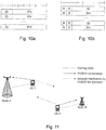
- Figures 10A and 10B show non-limiting examples of message formats for multiple SRS PHRs.
- the examples include the possibility that a report only reports for a single SRS process.
- the identifier (ID) is an SRS power control process identifier used in an SRS configuration and may use two reserved bits in section 6.1.1.3 of 3GPP TS 36.321, v11.0.0. Respective Power Headrooms (PHs) being reported by the PHRs are indicated in the figure.
- Figure 10B shows another alternative format for multiple SRS PHRs where the ID is an SRS power control process identifier used in the UE configuration and R is a reserved bit or bits.
- Other example formats include reporting SRS PHR from multiple cells in line with Extended Power Headroom MAC Control Element specified in Section 6.1.3.6 of TS 36.321 Rel-11, v11.0.0 and aggregating PUSCH and SRS PHR in same MAC control element.
- the MAC sub-header for SRS PHR given as examples 10A and 10B would include L field since the sizes are variable. In other formatting examples where the size is fixed the L field would not be present.
- the ID may be omitted, and in such a case, the ID is implicit with respect to the order of the PH, e.g., first PH corresponds to SRS process with lowest ID, second PH to second lowest ID, etc.
- an SRS PHR may be determined by a UE, e.g. the wireless terminal 210.
- the SRS PHR is reported by a UE for a single SRS process for a single carrier assuming no other transmission.
- PHR P CMAX , c ⁇ P SRS _ OFFSET , c m ⁇ 10 log 10 M SRS , c ⁇ P 0 _ PUSCH , c j ⁇ ⁇ c j ⁇ PL ′ ⁇ f SRS , c i
- the UE may scale the SRS transmitted power P ⁇ SRS,c ( i ) for the serving cell c in subframe i such that the condition: ⁇ c w i ⁇ P ⁇ SRS , c i ⁇ P ⁇ CMAX i is satisfied, where P ⁇ SRS,c ( i ) is the linear value of P SRS,c ( i ), where P ⁇ CMAX ( i ) is the linear value of the maximum transmit power PCMAX in subframe i, and where w(i) is a scaling factor of of serving cell c and 0 ⁇ w(i) ⁇ 1.
- the w(i) values are the same across serving cells.
- a SRS PHR transmission or more generally a transmit power report for an uplink reference signal transmission configuration, may be initiated by one or more of the following example reporting methods:
- Non-limiting examples of changes to the SRS process or PHR reporting mechanism include: the pathloss from the downlink reference resource changes compared to a threshold, the set of SRS processes that share the accumulated TPC command changes, and/or the reporting periodicity of PHR changes for one or several SRS processes.
- a transmit power control (TPC) accumulation function for PHRs and for power controlling of the SRS transmission may be independently configured per SRS process or may be configured to be shared between certain SRS processes.
- SRS TPC commands may be sent independently to a specific SRS process or processes, and hence, not affect the closed-loop power control for PUSCH or PUCCH.
- a path loss component of the SRS power control formula is configured at a higher protocol layer towards specified reference signals.
- the UE e.g.
- the first wireless terminal 210 may be configured by the eNB e.g. the first network node 212, to measure the path loss on a specific reference radio resource such as: a specific channel state information-reference signals (CSI-RS), sets of CSI-RS, or a common reference signal (CRS) of a certain cell.
- CSI-RS channel state information-reference signals
- CRS common reference signal
- PL k is the pathloss for the specific configured reference radio resource used by the UE for the SRS transmission.
- Wireless terminals UE1 and UE2 are shown communicating with a network node Node A and a network node Node B.
- Wireless terminal UE1 may e.g. correspond to any one of the first wireless terminal 210 and the second wireless terminal 211 and the wireless terminal UE to the other one of the first wireless terminal 210 and the second wireless terminal 211.
- network node Node A may correspond to the first network node 212 and the network node Node B may correspond to the second network node 214.
- UE1 is served by Node A and the UE2 by Node B.
- UEs transmit over the PUSCH to their respective serving nodes, they also cause interference at non-serving nodes, e.g. UE1 cause interference at Node B.
- Accurate knowledge of the induced interference may be obtained by estimating the channel between the UE and the non-serving node, e.g. between UE1 and Node B, using the SRS sent by the UE, in the example UE1.
- the channel knowledge may be used by one or multiple distributed schedulers to coordinate the pre-coder choice for the PUSCH transmissions. It is realized that embodiments herein may be used for and facilitate gaining such knowledge.
- the received power of the SRS transmitted by the UE needs to be sufficiently high.
- P SRS , c i min P CMAX , c , P SRS _ OFFSET , c m + 10 log 10 M SRS , c + P 0 _ PUSCH , c j + ⁇ c j ⁇ PL max + f SRS , c i
- PL max is the maximum pathloss for, e.g., a set of higher-layer configured measurement resources.
- NodeA may transmit measurement resource configuration A
- NodeB may transmit measurement resource configuration B.
- the UE is higher-layer configured to control its transmit power with respect to the largest path loss among the measurement resource configurations A and B.
- a PHR (e.g. in addition to other triggers) may then be triggered when maximum path loss is switched between the measurement resources.
- both the first wireless terminal 210 and the second wireless terminal 211, as well as both the wireless terminals UE1 and UE2 may operate according to embodiments herein.
- Figure 12 shows portions of an example telecommunications network, and particularly two network nodes, e.g., a first network node 12 and a second network node 14.
- the first network node 12 may correspond to the first network node 212 and the second network node 14 may correspond to the second network node 214.
- the first network node 12 and second network node 14 may or may not be members of a same radio access network.
- the first network node 12 and the second network node 14 may be base station nodes.
- the first network node 12 and/or the second network node 14 may be some other type of node.
- the first network node 12 and the second network node 14 communicate over a radio interface with a UE 10 that includes a radio communications circuitry 20, one or more data and signaling processors 22, and one or more user interfaces 28.
- the UE 10 may correspond to the wireless terminal 210.
- the data and signaling processors 22 includes an SRS PHR processor 23 for managing one or more SRS processes. Two SRS processes 24 and 26 are shown in this example. Each SRS process may receive an SRS trigger from a corresponding network node, and in response, the SRS PHR processor 23 sends an SRS PHR to that triggering node as shown. Alternatively, the SRS PHR processor 23 may detect one or more conditions as an SRS PHR trigger. In response to a trigger, the SRS PHR processor 23 calculates an SRS PHR for each of one or more SRS processes triggered and generates one or more SRS PHRs to be transmitted via the radio communications circuitry 20 to one or more of the network nodes.
- Figure 13 shows other portions of the example telecommunications network with further example details for the first network node 12 and second network node 14.
- the first network node 12 and the second network node 14 each communicate over the radio interface with UE 10 using respective radio communications circuitry 36 and 46 and can communicate with each other as well as with other network nodes via respective communication interfaces 34 and 44.
- Each node includes one or more respective data and signaling processors 30 and 40 that each includes one or more SRS PHR processor(s) 32 and 42 for managing one or more SRS processes, and if network node triggers are used, they monitor trigger conditions and generate trigger signals to be sent to appropriate UE(s) via respective radio communications circuitry.
- the SRS PHR processor(s) 32 and 42 may be programmed to determine whether a PHR for a UE SRS process is unavailable, inaccurate, or out-of-date to send an SRS PHR trigger message to the UE. In response to the trigger, the SRS PHR processor(s) 32 and 42 receive one or more SRS PHRs from one or more UEs and use the SRS PHR to determine if the UE is power limited when transmitting a certain SRS resource.
- the SRS PHR processor(s) 32 and 42 may also use received SRS PHR(s) to determine uplink channel quality and/or path loss associated with the UE, e.g., by combining estimated UE SRS transmit power based on the PHR with an estimate of received power for the SRS signal received at the network node which is determined by the SRS PHR processor(s) 32 and 42.
- Embodiments herein relating to a method, performed by the first wireless terminal 210, for handling uplink transmit power reporting in the radio access network 202, will now be further elaborated and described with reference to the flowchart depicted in Figure 14 .
- the method comprises the following actions, which actions may be taken in any suitable order. Further, actions may be combined.
- the first wireless terminal 210 may obtain a trigger triggering the provision of the respective transmit power report according to Action 1402 below.
- Obtaining the trigger may comprise receiving a trigger message from the first network node 212 or the first wireless terminal 210 may detect one or more conditions as the trigger.
- This action may fully or partly correspond to action 401 and S10 discussed above.
- the first wireless terminal 210 provides a respective transmit power report for at least one of multiple uplink reference signal transmission configurations comprised in the first wireless terminal 210. Each configuration configures transmission, by the first wireless terminal 210, of an uplink reference signal.
- the respective transmit power report provides information abouta transmit power used by the first wireless terminal 210 for transmitting the uplink reference signal.
- the respective transmit power report may comprise a respective power headroom report (PHR) and/or the uplink reference signal may comprise a sounding reference signal (SRS).
- PHR power headroom report
- SRS sounding reference signal
- said at least one uplink reference signal transmission configuration is associated with a respective path loss measurement by the first wireless terminal 210, which respective path loss measurement is based on a specific downlink reference radio resource.
- the transmit power of the uplink reference signal according to said at least one uplink reference signal transmission configuration may be based on the respective path loss measurement associated with said at least one uplink reference signal transmission configuration.
- said respective transmit power report comprises a respective identifier identifying said at least one reference signal transmission configuration.
- Each of the multiple uplink reference signal transmission configurations may comprise a set of parameters that indicates one or more of the following:
- This action may fully or partly correspond to action 402 and S11 discussed above.
- the first wireless terminal 210 sends the respective transmit power report to one or more network nodes, e.g. the first network node 212, of the cellular radio system 201.
- This action may fully or partly correspond to action 403 and S12 discussed above.
- the first wireless terminal 210 transmits, for receipt by the one or more network nodes, e.g. the first network node 212, the uplink reference signal according to said at least one uplink reference signal transmission configuration.
- This action may fully or partly correspond to action 404 discussed above.
- the first wireless terminal 210 may comprise an arrangement schematically depicted in Figure 15 .
- the first wireless terminal 210 typically comprise a receiving port 1501 configured to participate in downlink wireless transmission.
- the receiving port 1501 may fully or partly correspond to the radio communications circuitry 20 in Figure 12 .
- the first wireless terminal 210 or an obtaining circuitry 1502 comprised in the first wireless terminal 210, is configured to obtain the trigger triggering the provision of the respective transmit power report.
- Configured to obtain the trigger may comprise the first wireless terminal 210, or the obtaining circuitry 1502, being configured to receive the trigger message from the first network node 212 or the first wireless terminal 210, e.g. the obtaining circuitry 1502, being configured detect said one or more conditions as the trigger.
- the obtaining circuitry 1502 may fully or partly correspond to the radio communications circuitry 20 and/or data and signalling processor(s) 22 in Figure 12 .
- the first wireless terminal 210 or a providing circuitry 1503 comprised in the first wireless terminal 210, is configured to provide the respective transmit power report for said at least one of multiple uplink reference signal transmission configurations comprised in the first wireless terminal 210.
- the providing circuitry may fully or partly correspond to the data and signalling processor(s) 22 and/or SRS power headroom processor 23 in Figure 12 .
- first wireless terminal 210 or a sending port 1504 comprised in the first wireless terminal 210, may be configured to send the respective transmit power report to said one or more network nodes, e.g. the first network node 212, of the cellular radio system 201.
- the sending port 1504 may fully or partly correspond to the radio communications circuitry 20 in Figure 12 .
- the first wireless terminal 210 e.g. the sending port 1504 is further configured to transmit, for receipt by the one or more network nodes, e.g. the first network node 212, the uplink reference signal according to said at least one uplink reference signal transmission configuration.
- the sending port 1504 may be configured to participate in uplink wireless transmission.
- the embodiments of the first wireless terminal 210 may be fully or partly implemented through one or more processors, such as a processor 1505 depicted in Figure 15 , together with a computer program for performing the functions and actions of embodiments herein.
- processors such as a processor 1505 depicted in Figure 15
- the circuitry and ports discussed above may be fully or partially implemented by the processor 1505.
- the processor 1505 may fully or partly correspond to the data and signalling processor(s) 22 in Figure 12 .
- a computer program 1801a comprising instructions that when executed by a a data processing apparatus, e.g. the processor 1505, causes the first wireless terminal 210 to perform the method according to embodiments herein as described above.
- a computer program product comprising a computer-readable medium on which the computer program 1801a is stored.
- a computer-readable medium is a memory card or a memory stick 1802a as in Figure 18a , a disc storage medium 1803a such as a CD or DVD as in Figure 18b , a mass storage device 1804a as in Figure 18c .
- the mass storage device 1804a is typically based on hard drive(s) or Solid State Drive(s) (SSD).
- SSD Solid State Drive
- the mass storage device 1804a may be such that is used for storing data accessible over a computer network 1805a, e.g. the Internet or a Local Area Network (LAN).
- a computer network 1805a e.g. the Internet or a Local Area Network (LAN).
- LAN Local Area Network
- the computer program 1801a may furthermore be provided as a pure computer program or comprised in a file or files.
- the file or files may be stored on the computer-readable memory and e.g. available through download e.g. over the computer network 1805a, such as from the mass storage device 1804a via a server.
- the server may e.g. be a web or file transfer protocol (ftp) server.
- the file or files may e.g. be executable files for direct or indirect download to and execution on the wireless terminal 210, e.g. on the processor 1505, or may be for intermediate download and compilation involving the same or another processor to make them executable before further download and execution.
- the wireless terminal 210 may further comprise a memory 1506 comprising one or more memory units.
- the memory 1506 is arranged to store data, such as configurations and/or applications involved in or for performing the functions and actions of embodiments herein.
- ports and circuitry 1501-1505 may refer to a combination of analog and digital circuits, and/or one or more processors configured with software and/or firmware (e.g., stored in memory) that, when executed by the one or more processors such as the processor 1505, perform as described above.
- processors as well as the other digital hardware, may be included in a single application-specific integrated circuit (ASIC), or several processors and various digital hardware may be distributed among several separate components, whether individually packaged or assembled into a system-on-a-chip (SoC).
- ASIC application-specific integrated circuit
- SoC system-on-a-chip
- the wireless terminal 210 may comprise a processing unit 1507, which may comprise one or more of the circuit(s) and/or port(s) etc mentioned above.
- processing circuit may relate to a processing unit, a processor, an application specific integrated circuit (ASIC), a field-programmable gate array (FPGA) or the like.
- ASIC application specific integrated circuit
- FPGA field-programmable gate array
- a processor, an ASIC, an FPGA or the like may comprise one or more processor kernels.
- the processing circuit may be embodied by a software and/or hardware module.
- Embodiments herein relating to a method, performed by the first network node 212, for handling uplink transmit power reporting in the radio access network 202, will now be further elaborated and described with reference to the flowchart depicted in Figure 16 .
- the method comprises the following actions, which actions may be taken in any suitable order. Further, actions may be combined.
- the first network node 212 may send, to the first wireless terminal 210, a trigger for triggering the first wireless terminal 210 to provide the respective transmit power report according to Action 1602 below.
- This action may fully or partly correspond to action 401 and/or S1 and/or S2 discussed above.
- the first network node 212 receives, from the first wireless terminal 210, a respective transmit power report for at least one of multiple uplink reference signal transmission configurations comprised in the first wireless terminal 210. Each configuration configures transmission, by the first wireless terminal 210, of an uplink reference signal.
- the respective transmit power report provides information about a transmit power used by the first wireless terminal 210 for transmitting the uplink reference signal.
- the respective transmit power report may comprise a respective power headroom report (PHR), and/or the uplink reference signal may comprise a sounding reference signal (SRS).
- Said at least one uplink reference signal transmission configuration may be associated with a respective path loss measurement by the first wireless terminal 210, which respective path loss measurement is based on a specific downlink reference radio resource.
- the transmit power of the uplink reference signal transmitted according to said at least one uplink reference signal transmission configuration may be based on the path loss measurement associated with said at least one uplink reference signal transmission configuration.
- said respective transmit power report comprises a respective identifier identifying said at least one uplink reference signal transmission configuration.
- This action may fully or partly correspond to action 403 and/or S3 discussed above.
- the first network node 212 may receive, from the first wireless terminal 210, the uplink reference signal according to said at least one uplink reference signal transmission configuration.
- This action may fully or partly correspond to action 404 discussed above.
- the first network node 212 may determine, based on the received uplink reference signal and the received respective transmit power report, uplink quality and/or path loss associated with the first wireless terminal 210.
- This action may fully or partly correspond to action 405 and/or S4 discussed above.
- the first network node 212 may comprise an arrangement schematically depicted in Figure 17 .
- the first network node 212 or a receiving port 1701 comprised in first network node 212, is configured to receive, from the first wireless terminal 210, the respective transmit power report for said at least one of multiple uplink reference signal transmission configurations.
- the first network node 212 e.g. the receiving port 1701, may be further configured to receive, from the first wireless terminal 210, the uplink reference signal according to said at least one uplink reference signal transmission configuration.
- the receiving port 1701 may be configured to participate in uplink wireless reception.
- the receiving port 1701 may fully or partly correspond to the radio communications circuitry 36 in Figure 13 .
- the first network node 212 may be configured to determine, based on the received uplink reference signal and the received respective transmit power report, said uplink quality and/or path loss associated with the first wireless terminal 210.
- the determining circuitry 1702 may fully or party correspond to the data and signaling processors(s) 30 and/or the PHR SRS processor(s) 32 in Figure 13 .
- the first network node 212 may be configured to send, to the first wireless terminal 210, said trigger for triggering the first wireless terminal 210 to provide the respective transmit power report.
- the sending port 1703 may be configured to participate in downlink wireless transmission.
- the sending port 1703 may fully or partly correspond to the radio communications circuitry 36 in Figure 13 .
- the embodiments of the first network node 212 may be fully or partly implemented through one or more processors, such as a processor 1704 depicted in Figure 17 , together with a computer program for performing the functions and actions of embodiments herein.
- processors such as a processor 1704 depicted in Figure 17
- the circuitry and ports discussed above may be fully or partially implemented by the processor 1704.
- the processor 1704 may fully or partly correspond to the data and signaling processors(s) 30 and/or the PHR SRS processor(s) 32 in Figure 13 .
- a computer program 1801b comprising instructions that when executed by a a data processing apparatus, e.g. the processor 1704, causes the first network node 212 to perform the method according to embodiments herein as described above.
- a computer program product comprising a computer-readable medium on which the computer program 1801b is stored.
- a computer-readable medium is a memory card or a memory stick 1802b as in Figure 18a , a disc storage medium 1803b such as a CD or DVD as in Figure 18b , a mass storage device 1804b as in Figure 18c .
- the mass storage device 1804b is typically based on hard drive(s) or Solid State Drive(s) (SSD).
- SSD Solid State Drive
- the mass storage device 1804b may be such that is used for storing data accessible over a computer network 1805b, e.g. the Internet or a Local Area Network (LAN).
- a computer network 1805b e.g. the Internet or a Local Area Network (LAN).
- LAN Local Area Network
- the computer program 1801b may furthermore be provided as a pure computer program or comprised in a file or files.
- the file or files may be stored on the computer-readable memory and e.g. available through download e.g. over the computer network 1805b, such as from the mass storage device 1804b via a server.
- the server may e.g. be a web or ftp server.
- the file or files may e.g. be executable files for direct or indirect download to and execution on the first network node 212, e.g. on the processor 1704, or may be for intermediate download and compilation involving the same or another processor to make them executable before further download and execution.
- the first network node 212 may further comprise a memory 1705 comprising one or more memory units.
- the memory 1705 is arranged to store data, such as configurations and/or applications involved in or for performing the functions and actions of embodiments herein.
- ports and circuitry 1701-1703 may refer to a combination of analog and digital circuits, and/or one or more processors configured with software and/or firmware (e.g., stored in memory) that, when executed by the one or more processors such as the processor 1704, perform as described above.
- processors as well as the other digital hardware, may be included in a single application-specific integrated circuit (ASIC), or several processors and various digital hardware may be distributed among several separate components, whether individually packaged or assembled into a system-on-a-chip (SoC).
- ASIC application-specific integrated circuit
- SoC system-on-a-chip
- the network node 212 may comprise a processing unit 1706, which may comprise one or more of the circuit(s) and/or port(s) etc mentioned above.
- processing circuit may relate to a processing unit, a processor, an application specific integrated circuit (ASIC), a field-programmable gate array (FPGA) or the like.
- ASIC application specific integrated circuit
- FPGA field-programmable gate array
- a processor, an ASIC, an FPGA or the like may comprise one or more processor kernels.
- the processing circuit may be embodied by a software and/or hardware module.
- Figures 18a-c are schematic drawings for illustrating embodiments related to computer program embodiments and have been used and discussed above. Note that the same Figures 18a-c have been used to illustrate separate embodiments regarding the first wireless terminal 210 and the first network node 212. The only reason for this is to avoid duplicating the illustrations in Figure 18a-c , and shall thus not be construed as that e.g. computer programs related to the first wireless terminal 210 and first network node 212 are the same and/or need to be stored together on the same computer readable medium. To accentuate that Figures 18a-c in fact show separate embodiments, different numerals have been used for the same element show in Figures 18a-c , e.g. there are two separate computer programs 1801a and 1801b, which may be on respective separate computer readable medium, e.g. the computer program 1801a on memory stick 1802a, and separate from this, the computer program 1801b on another memory stick 1802b.
- the technology described above may provide one or more Power Headroom Report(s) (PHR(s)), or other type of transmit power report, specifically for a UE's reference signal transmissions, e.g., SRS transmissions, to each of one or more network nodes.
- PHR(s) may then be used for example to provide closed-loop power control specific to that reference signal and preferably independent of the power of other uplink transmissions, e.g., other data channels such as PUSCH transmissions in LTE.
- PHR(s) are used as example transmit power reports
- SRS transmissions are used as example reference signals. But the technology applies to any type of transmit power report and/or reference signal that is known by the UE and the network node prior to the UE transmitting that reference signal to the network node.
- the technology disclosed herein may provide a UE with one or more SRS processes or configurations.
- Each SRS process or configuration may be associated with one network node that the UE is within communication range of.
- Example network nodes include macro base stations, low power base stations, CoMP Tx and Rx points, etc.
- An SRS process or configuration may include a set of parameters that defines that the UE is capable of transmitting SRS, e.g., in a set of one or more subframes, and indicates for example how SRS transmission from the UE is triggered, how the SRS transmission has its path loss estimate defined, whether the SRS transmission is unique for a certain frequency carrier, which time and/or frequency resources should be used for SRS transmission, what timing alignment if any is needed, and/or whether the SRS process has a corresponding SRS-specific power-control loop. Other parameters may be included.
- a PHR may be sent by the UE for each of one or more SRS processes active at the UE to one or more network nodes.
- a UE may optionally receive an SRS PHR trigger message from a network node.
- the UE may simply detect one or more conditions as an SRS PHR trigger.
- the UE may calculate an SRS PHR for one or more SRS processes and then transmit one or more SRS PHRs to one or more network nodes for each of one or more SRS processes at the UE.
- the technology disclosed herein may concern and/or involve methods in one or more network nodes for triggering UE uplink reference signal-specific transmit power report(s) from a UE, e.g., SRS PHR(s).
- SRS PHR(s) are received from a UE for each SRS process.
- the network node may determine from one or more received PHR(s) if the UE is power limited or close to power limited when transmitting SRS.
- the network node may also use received SRS PHR(s) from a UE to determine uplink channel quality and/or path loss associated with the UE, e.g., by combining estimated UE SRS transmit power based on the PHR with an estimate of received power for the SRS signal received at the network node.
- a network node may optionally determine whether a PHR for a UE SRS process is unavailable, inaccurate, or out of date, and if so, send an SRS PHR trigger message to the UE.
- one or more conditions may simply be detected by the UE or the network node as an SRS PHR trigger.
- the network node receives one or more SRS PHRs from one or more UEs and uses the SRS PHR, e.g., as described above.
- node and/or “network node” may encompass nodes using any technology including, e.g., high speed packet access (HSPA), long-term evolution (LTE), code-division multiple access (CDMA) 2000, GSM, etc. or a mixture of technologies such as with a multi-standard radio (MSR) node (e.g., LTE/HSPA, GSM/HS/LTE, CDMA2000/LTE, etc).
- HSPA high speed packet access
- LTE long-term evolution
- CDMA code-division multiple access 2000
- GSM etc.
- MSR multi-standard radio
- nodes e.g., base station, eNode B, Node B, relay, base transceiver station (BTS), donor node serving a relay node (e.g., donor base station, donor Node B, donor eNB), supporting one or more radio access technologies, and transmit and receive points in a CoMP context.
- nodes e.g., base station, eNode B, Node B, relay, base transceiver station (BTS), donor node serving a relay node (e.g., donor base station, donor Node B, donor eNB), supporting one or more radio access technologies, and transmit and receive points in a CoMP context.
- BTS base transceiver station
- Example advantages of the technology and embodiments herein include the fact that the power control mechanism for the UE's reference signaling, e.g., SRS, is separated from other uplink channels, e.g., the PUSCH, and thus functions independently of the uplink channel. This is important when the uplink and downlink are decoupled, which is a typical case in a heterogeneous network scenario, and in any situation where the UE reference signaling power control must be able to function as a separate power control entity.
- the node can combine this power level with the already known power level of the PUSCH to improve link adaptation of the PUSCH.
- Other example applications for an independent power control for SRS as compared to, e.g., PUSCH include targeting different reception point(s) with SRS as compared to UL data channels.
- Embodiments herein may relate to a method performed by a base station comprised in a cellular system, such as a telecommunications system for mobile communications, the base station, a method performed by a user equipment, and the user equipment.
- a base station comprised in a cellular system, such as a telecommunications system for mobile communications
- the base station a method performed by a user equipment
- the user equipment may be applied for or in the context of cell reselection for the user equipment.
- the computer program instructions may be provided to produce a machine, such that the instructions, which execute via a processor of a computer and/or other programmable data processing apparatus, create means for implementing the functions/acts specified in the block diagrams and/or flowchart block or blocks of the present disclosure.
- the above-mentioned computer program instructions may be stored in a computer-readable memory that can direct a computer or other programmable data processing apparatus to function in a particular manner, such that the instructions stored in the computer-readable memory produce an article of manufacture including instructions which implement the function/act specified in the block diagrams and/or flowchart block or blocks of the present disclosure.
- the computer program instructions may also be loaded onto a computer or other programmable data processing apparatus to cause a series of operational steps to be performed on the computer or other programmable apparatus to produce a computer-implemented process such that the instructions which execute on the computer or other programmable apparatus provide steps for implementing the functions/acts specified in the block diagrams and/or flowchart block or blocks of the present disclosure.
- the term "memory” may refer to a hard disk, a magnetic storage medium, a portable computer diskette or disc, flash memory, random access memory (RAM) or the like. Furthermore, the memory may be an internal register memory of a processor.
- the expression “configured to” may mean that a processing circuit is configured to, or adapted to, by means of software or hardware configuration, perform one or more of the actions described herein.
- number may be any kind of digit, such as binary, real, imaginary or rational number or the like. Moreover, “number”, “value” may be one or more characters, such as a letter or a string of letters. “number”, “value” may also be represented by a bit string.
- the expression “transmit” and “send” are typically interchangeable. These expressions may include transmission by broadcasting, uni-casting, group-casting and the like. In this context, a transmission by broadcasting may be received and decoded by any authorized device within range. In case of uni-casting, one specifically addressed device may receive and encode the transmission. In case of group-casting, a group of specifically addressed devices may receive and decode the transmission.
Landscapes
- Engineering & Computer Science (AREA)
- Computer Networks & Wireless Communication (AREA)
- Signal Processing (AREA)
- Mobile Radio Communication Systems (AREA)
Claims (13)
- Verfahren, durchgeführt von einem drahtlosen Endgerät (10, 210), zum Handhaben von Uplink-Sendeleistungsmeldungen in einem Funkzugangsnetz (2, 202) eines zellularen Funksystems (1, 201), wobei das Verfahren Folgendes umfasst:- Bereitstellen (402, 1402) einer jeweiligen Sendeleistungsmeldung für mindestens eine von mehreren Uplink-Referenzsignalübertragungskonfigurationen, die in dem drahtlosen Endgerät (10, 210) umfasst sind, wobei jede der mehreren Uplink-Referenzsignalübertragungskonfigurationen die Übertragung, durch das drahtlose Endgerät (10, 210), eines Uplink-Referenzsignals konfiguriert, wobei die jeweilige Sendeleistungsmeldung Informationen über eine Sendeleistung, die von dem drahtlosen Endgerät (10, 210) zum Übertragen des Uplink-Referenzsignals auf einem Träger verwendet wird, und eine Leistungsreservemeldung, die eine Übertragung auf dem gemeinsamen physikalischen Uplink-Kanal, PUSCH, oder eine Übertragung auf PUSCH und dem physikalischen Uplink-Steuerkanal, PUCCH, auf dem Träger annimmt, bereitstellt, wobei die mindestens eine der mehreren Uplink-Referenzsignalübertragungskonfigurationen mit einer jeweiligen Pfadverlustmessung durch das drahtlose Endgerät (10, 210) assoziiert ist und wobei die Sendeleistung des Uplink-Referenzsignals gemäß der mindestens einen der mehreren Uplink-Referenzsignalübertragungskonfigurationen auf der jeweiligen mit der mindestens einen der mehreren Uplink-Referenzsignalübertragungskonfigurationen assoziierten Pfadverlustmessung beruht, und- Senden (403, 1403) der jeweiligen Sendeleistungsmeldung und der Leistungsreservemeldung an einen oder mehrere Netzknoten (12, 212, 14, 214) des zellularen Funksystems (1, 201).
- Verfahren nach Anspruch 1, wobei die jeweilige Pfadverlustmessung auf einer spezifischen Downlink-Referenzfunkressource beruht.
- Verfahren nach einem der Ansprüche 1-2, wobei das Verfahren ferner Folgendes umfasst:- Übertragen (404, 1404), zum Empfang durch den einen oder die mehreren Netzknoten (12, 212, 14, 214), des Uplink-Referenzsignals gemäß der mindestens einen der mehreren Uplink-Referenzsignalübertragungskonfigurationen.
- Verfahren nach einem der Ansprüche 1-3, wobei die jeweilige Sendeleistungsmeldung eine jeweilige Kennung umfasst, welche die mindestens eine der mehreren Uplink-Referenzsignalübertragungskonfigurationen identifiziert.
- Verfahren nach einem der Ansprüche 1-4, wobei das Verfahren ferner Folgendes umfasst:- Erhalten (401, 1401) eines Auslösers, der die Bereitstellung der jeweiligen Sendeleistungsmeldung auslöst.
- Verfahren nach Anspruch 5, wobei das Erhalten (401, 1401) des Auslösers Empfangen einer Auslösenachricht von einem ersten Netzknoten (12, 212) von dem einen oder den mehreren Netzknoten (12, 212, 14, 214) oder dem drahtlosen Endgerät (10, 210), der bzw. das eine oder mehrere Bedingungen als den Auslöser erkennt, umfasst.
- Verfahren nach einem der vorherigen Ansprüche, wobei jede der mehreren Uplink-Referenzsignalübertragungskonfigurationen einen Satz von Parametern umfasst, der eines oder mehrere der Folgenden angibt:wie die Übertragung des Uplink-Referenzsignals ausgelöst wird,wie die Pfadverlustschätzung für die Übertragung des Uplink-Referenzsignals definiert ist,ob die Übertragung des Uplink-Referenzsignals für einen bestimmten Frequenzträger eindeutig ist,welche Zeit- und/oder Frequenzressourcen zur Übertragung des Uplink-Referenzsignals verwendet werden sollten,welche Taktabstimmung, wenn überhaupt, benötigt wird, und/oder ob jede der mehreren Uplink-Referenzsignalübertragungskonfigurationen eine entsprechende für das Uplink-Referenzsignal spezifische Leistungsregelungsschleife aufweist.
- Verfahren nach einem der vorhergehenden Ansprüche, wobei die jeweilige Sendeleistungsmeldung eine jeweilige Leistungsreservemeldung, PHR, umfasst und das Uplink-Referenzsignal ein Sondierungsreferenzsignal, SRS, umfasst.
- Computerprogramm (1801a), das bei Ausführung durch einen Prozessor (1505) eine drahtlose Vorrichtung (10, 210) dazu veranlasst, das Verfahren gemäß einem der Ansprüche 1-8 durchzuführen.
- Verfahren, durchgeführt von einem Netzknoten (12, 212), zum Handhaben von Uplink-Sendeleistungsmeldungen in einem Funkzugangsnetz (2, 202) eines zellularen Funksystems (1, 201), wobei der Netzknoten (12, 212) in dem zellularen Funksystem (1, 201) umfasst ist, wobei das Verfahren Folgendes umfasst:- Empfangen (403, 1602), von einem drahtlosen Endgerät (10, 210), einer jeweiligen Sendeleistungsmeldung für mindestens eine von mehreren Uplink-Referenzsignalübertragungskonfigurationen, die in dem drahtlosen Endgerät (10, 210) umfasst sind, wobei jede der mehreren Uplink-Referenzsignalübertragungskonfigurationen die Übertragung, durch das drahtlose Endgerät (10, 210), eines Uplink-Referenzsignals konfiguriert, wobei die jeweilige Sendeleistungsmeldung Informationen über eine Sendeleistung, die von dem drahtlosen Endgerät (10, 210) zum Übertragen des Uplink-Referenzsignals auf einem Träger verwendet wird, und eine Leistungsreservemeldung, die eine Übertragung auf dem gemeinsamen physikalischen Uplink-Kanal, PUSCH, oder eine Übertragung auf PUSCH und dem physikalischen Uplink-Steuerkanal, PUCCH, auf dem Träger annimmt, bereitstellt, wobei die mindestens eine der mehreren Uplink-Referenzsignalübertragungskonfigurationen mit einer jeweiligen Pfadverlustmessung durch das drahtlose Endgerät (10, 210) assoziiert ist und wobei die Sendeleistung des Uplink-Referenzsignals gemäß der mindestens einen der mehreren Uplink-Referenzsignalübertragungskonfigurationen auf der jeweiligen mit der mindestens einen der mehreren Uplink-Referenzsignalübertragungskonfigurationen assoziierten Pfadverlustmessung beruht.
- Computerprogramm (1801b), das bei Ausführung durch einen Prozessor (1704) einen Netzknoten (12, 212) dazu veranlasst, das Verfahren nach Anspruch 10 durchzuführen.
- Drahtloses Endgerät (10, 210) zum Handhaben von Uplink-Sendeleistungsmeldungen in einem Funkzugangsnetz (2, 202) eines zellularen Funksystems (1, 201), wobei das drahtlose Endgerät (10, 210) konfiguriert ist zum:- Bereitstellen einer jeweiligen Sendeleistungsmeldung für mindestens eine von mehreren Uplink-Referenzsignalübertragungskonfigurationen, die in dem drahtlosen Endgerät (10, 210) umfasst sind, wobei jede der mehreren Uplink-Referenzsignalübertragungskonfigurationen die Übertragung, durch das drahtlose Endgerät (10, 210), eines Uplink-Referenzsignals konfiguriert, wobei die jeweilige Sendeleistungsmeldung Informationen über eine Sendeleistung, die von dem drahtlosen Endgerät (10, 210) zum Übertragen des Uplink-Referenzsignals auf einem Träger verwendet wird, und eine Leistungsreservemeldung, die eine Übertragung auf dem gemeinsamen physikalischen Uplink-Kanal, PUSCH, oder eine Übertragung auf PUSCH und dem physikalischen Uplink-Steuerkanal, PUCCH, auf dem Träger annimmt, bereitstellt, wobei die mindestens eine der mehreren Uplink-Referenzsignalübertragungskonfigurationen mit einer jeweiligen Pfadverlustmessung durch das drahtlose Endgerät (10, 210) assoziiert ist und wobei die Sendeleistung des Uplink-Referenzsignals gemäß der mindestens einen der mehreren Uplink-Referenzsignalübertragungskonfigurationen auf der jeweiligen mit der mindestens einen der mehreren Uplink-Referenzsignalübertragungskonfigurationen assoziierten Pfadverlustmessung beruht, und- Senden der jeweiligen Sendeleistungsmeldung und der Leistungsreservemeldung an einen oder mehrere Netzknoten (12, 212, 14, 214) des zellularen Funksystems (1, 201).
- Netzknoten (12, 212) zum Handhaben von Uplink-Sendeleistungsmeldungen in einem Funkzugangsnetz (2, 202) eines zellularen Funksystems (1, 201), wobei der Netzknoten (12, 212) derart konfiguriert ist, dass er in dem zellularen Funksystem (1, 201) umfasst ist, wobei der Netzknoten (12, 212) ferner konfiguriert ist zum:- Empfangen, von einem drahtlosen Endgerät (10, 210), einer jeweiligen Sendeleistungsmeldung für mindestens eine von mehreren Uplink-Referenzsignalübertragungskonfigurationen, die in dem drahtlosen Endgerät (10, 210) umfasst sind, wobei jede der mehreren Uplink-Referenzsignalübertragungskonfigurationen die Übertragung, durch das drahtlose Endgerät (10, 210), eines Uplink-Referenzsignals konfiguriert, wobei die jeweilige Sendeleistungsmeldung Informationen über eine Sendeleistung, die von dem drahtlosen Endgerät (10, 210) zum Übertragen des Uplink-Referenzsignals auf einem Träger verwendet wird, und eine Leistungsreservemeldung, die eine Übertragung auf dem gemeinsamen physikalischen Uplink-Kanal, PUSCH, oder eine Übertragung auf PUSCH und dem physikalischen Uplink-Steuerkanal, PUCCH, auf dem Träger annimmt, bereitstellt, wobei die mindestens eine der mehreren Uplink-Referenzsignalübertragungskonfigurationen mit einer jeweiligen Pfadverlustmessung durch das drahtlose Endgerät (10, 210) assoziiert ist und wobei die Sendeleistung des Uplink-Referenzsignals gemäß der mindestens einen der mehreren Uplink-Referenzsignalübertragungskonfigurationen auf der jeweiligen mit der mindestens einen der mehreren Uplink-Referenzsignalübertragungskonfigurationen assoziierten Pfadverlustmessung beruht.
Applications Claiming Priority (2)
| Application Number | Priority Date | Filing Date | Title |
|---|---|---|---|
| US201361752153P | 2013-01-14 | 2013-01-14 | |
| PCT/SE2014/050032 WO2014109707A1 (en) | 2013-01-14 | 2014-01-14 | Handling uplink transmit power reporting |
Publications (3)
| Publication Number | Publication Date |
|---|---|
| EP2944134A1 EP2944134A1 (de) | 2015-11-18 |
| EP2944134A4 EP2944134A4 (de) | 2016-09-21 |
| EP2944134B1 true EP2944134B1 (de) | 2019-12-04 |
Family
ID=51167235
Family Applications (1)
| Application Number | Title | Priority Date | Filing Date |
|---|---|---|---|
| EP14738246.9A Active EP2944134B1 (de) | 2013-01-14 | 2014-01-14 | Handhabung von uplink-sendeleistungsmeldungen |
Country Status (3)
| Country | Link |
|---|---|
| US (1) | US20150358920A1 (de) |
| EP (1) | EP2944134B1 (de) |
| WO (1) | WO2014109707A1 (de) |
Families Citing this family (40)
| Publication number | Priority date | Publication date | Assignee | Title |
|---|---|---|---|---|
| CN103974319B (zh) * | 2013-01-29 | 2017-08-11 | 电信科学技术研究院 | 载波聚合下的功率余量上报方法和设备 |
| EP3116259B1 (de) * | 2014-03-06 | 2019-05-08 | Sharp Kabushiki Kaisha | Endgerätevorrichtung, basisstationsvorrichtung, kommunikationssystem, steuerungsverfahren und integrierte schaltung |
| CN105099631A (zh) * | 2014-04-17 | 2015-11-25 | 北京三星通信技术研究有限公司 | 一种处理灵活双工的方法和设备 |
| US9930626B2 (en) * | 2014-05-09 | 2018-03-27 | Futurewei Technologies, Inc. | Device, network, and method for communications with dynamic adaptation |
| US9426759B2 (en) * | 2014-09-15 | 2016-08-23 | Qualcomm Incorporated | Aligning wireless local area network operations with power headroom reporting |
| EP3236596B1 (de) * | 2014-12-16 | 2020-04-08 | Fujitsu Limited | Downlink-kanal-schätzungsverfahren und -vorrichtung auf basis eines klangreferenzsignals und kommunikationssystem |
| WO2017049486A1 (zh) * | 2015-09-23 | 2017-03-30 | 华为技术有限公司 | 终端设备、网络设备、上行参考信号发送方法和接收方法 |
| US9848424B2 (en) * | 2016-02-05 | 2017-12-19 | Telefonaktiebolaget Lm Ericsson (Publ) | SRS design for unlicensed carriers |
| US20190052450A1 (en) * | 2016-02-25 | 2019-02-14 | Telefonaktiebolaget Lm Ericsson (Publ) | Duplex Communication |
| US10547426B2 (en) * | 2016-03-14 | 2020-01-28 | Samsung Electronics Co., Ltd. | Transmission of sounding reference signals in communication systems with carrier aggregation |
| CN109075928B (zh) * | 2016-04-28 | 2021-09-28 | 索尼集团公司 | 上行链路导频信号接收方法和上行链路报告消息接收方法 |
| CA3022668C (en) | 2016-05-13 | 2019-07-16 | Telefonaktiebolaget Lm Ericsson (Publ) | Multi-subcarrier system with multiple numerologies |
| US10278088B2 (en) | 2016-07-22 | 2019-04-30 | Qualcomm Incorporated | Channel estimation enhancement |
| CN109565385B (zh) * | 2016-08-12 | 2021-02-12 | 华为技术有限公司 | 上行信道发送方法和装置 |
| CN107733606A (zh) * | 2016-08-12 | 2018-02-23 | 电信科学技术研究院 | 通信系统中上行参考信号的触发方法、发送方法及装置 |
| US11178622B2 (en) * | 2016-09-30 | 2021-11-16 | Huawei Technologies Co., Ltd. | Data processing method, terminal, and base station |
| JP6720408B2 (ja) * | 2016-10-07 | 2020-07-08 | テレフオンアクチーボラゲット エルエム エリクソン(パブル) | ワイヤレス通信ネットワークで動作する通信デバイス向けのビームカバレッジの提供に関する方法及び装置 |
| US10848258B2 (en) * | 2017-01-17 | 2020-11-24 | Qualcomm Incorporated | Coordinating reference signals in wireless communication |
| WO2018143595A1 (ko) * | 2017-02-02 | 2018-08-09 | 엘지전자 주식회사 | 분산 안테나 통신 시스템에서 기지국과 차량 단말 간 신호 송수신 방법 및 이를 위한 장치 |
| KR102247028B1 (ko) | 2017-05-04 | 2021-04-29 | 엘지전자 주식회사 | 무선 통신 시스템에서 상향링크 송수신 방법 및 이를 위한 장치 |
| WO2018205257A1 (en) | 2017-05-12 | 2018-11-15 | Qualcomm Incorporated | Nr phr design for mmwave deployment |
| US10945214B2 (en) * | 2017-08-18 | 2021-03-09 | Qualcomm Incorporated | Uplink power control |
| KR102314295B1 (ko) | 2017-09-07 | 2021-10-20 | 베이징 시아오미 모바일 소프트웨어 컴퍼니 리미티드 | 상향링크 빔 관리 |
| JP7025435B2 (ja) * | 2017-09-08 | 2022-02-24 | 株式会社Nttドコモ | 端末、基地局、無線通信システム及びul信号送信方法 |
| CN111279756B (zh) * | 2017-10-27 | 2025-05-09 | Oppo广东移动通信有限公司 | 传输数据的方法、终端设备和网络设备 |
| CN109803363B (zh) * | 2017-11-17 | 2022-11-08 | 华为技术有限公司 | 通信方法、通信装置和系统 |
| CN111771397B (zh) * | 2018-01-16 | 2024-04-16 | 诺基亚技术有限公司 | 监测用户设备能耗 |
| CN111641961B (zh) * | 2018-03-07 | 2022-01-11 | Oppo广东移动通信有限公司 | Srs功率余量上报的方法、终端设备及计算机存储介质 |
| US10750456B2 (en) * | 2018-09-07 | 2020-08-18 | T-Mobile Usa, Inc. | Systems and methods for managing cellular multi-connectivity |
| CN111954246B (zh) * | 2019-05-17 | 2023-04-25 | 中国移动通信集团安徽有限公司 | 下行链路评估方法、基站和设备 |
| CN110337141B (zh) * | 2019-06-17 | 2022-06-07 | Oppo广东移动通信有限公司 | 一种通信控制方法、终端、基站以及计算机存储介质 |
| CN112534891B (zh) * | 2019-07-19 | 2023-04-28 | Oppo广东移动通信有限公司 | 探测参考信号传输的上行功率控制的方法及装置 |
| US11671970B2 (en) * | 2019-08-07 | 2023-06-06 | Qualcomm Incorporated | LCP restriction enhancement |
| CN110536397A (zh) | 2019-08-13 | 2019-12-03 | 中兴通讯股份有限公司 | 一种信息发送方法、信息接收方法及装置 |
| CN113271618B (zh) * | 2020-02-14 | 2023-04-11 | 华为技术有限公司 | 一种功率控制方法及相关装置 |
| CN111901859B (zh) | 2020-05-14 | 2025-02-11 | 中兴通讯股份有限公司 | 功率控制方法、装置、服务节点、终端及存储介质 |
| CN116368876B (zh) * | 2020-10-12 | 2025-05-16 | 高通股份有限公司 | 用于可重配置智能表面链路的信道估计的srs功率控制方法 |
| CN117280786A (zh) * | 2021-08-03 | 2023-12-22 | Oppo广东移动通信有限公司 | Phr上报方法、装置、通信设备及存储介质 |
| US12170592B2 (en) | 2021-12-27 | 2024-12-17 | T-Mobile Usa, Inc. | Automated inspection of network state |
| US11950123B2 (en) | 2021-12-27 | 2024-04-02 | T-Mobile Usa, Inc. | Automated network state auditor |
Citations (1)
| Publication number | Priority date | Publication date | Assignee | Title |
|---|---|---|---|---|
| WO2012149968A1 (en) * | 2011-05-04 | 2012-11-08 | Nokia Siemens Networks Oy | Pathloss-based access node wake-up control |
Family Cites Families (13)
| Publication number | Priority date | Publication date | Assignee | Title |
|---|---|---|---|---|
| FR2940967B1 (fr) * | 2009-01-12 | 2012-07-20 | Inst Francais Du Petrole | Preparation d'un solide a base d'oxyde de zinc utilisable pour la purification d'un gaz ou d'un liquide |
| CA2756072A1 (en) * | 2009-03-30 | 2010-10-14 | Cerulean Pharma Inc. | Polymer-agent conjugates, particles, compositions, and related methods of use |
| US8938247B2 (en) * | 2009-04-23 | 2015-01-20 | Qualcomm Incorporated | Sounding reference signal for coordinated multi-point operation |
| US8437798B2 (en) * | 2009-04-27 | 2013-05-07 | Motorola Mobility Llc | Uplink scheduling support in multi-carrier wireless communication systems |
| US8315661B2 (en) * | 2009-12-31 | 2012-11-20 | Cellco Partnership | Enhanced power headroom reporting |
| CN101778416B (zh) * | 2010-02-10 | 2015-05-20 | 中兴通讯股份有限公司 | 功率上升空间的测量和报告方法及终端 |
| TWI555419B (zh) * | 2010-04-02 | 2016-10-21 | 聯發科技股份有限公司 | 管理多成分載波、緩存器狀態報告以及功率餘裕回報方法 |
| US9210671B2 (en) * | 2010-06-18 | 2015-12-08 | Telefonaktiebolaget L M Ericsson (Publ) | Methods of providing power headroom reports arranged in order of component carrier indices and related wireless terminals and base stations |
| US9036584B2 (en) * | 2010-08-09 | 2015-05-19 | Panasonic Intellectual Property Corporation Of America | Base station, mobile station, method for transmitting calculation parameters for power headroom, and method for transmitting power headroom |
| KR101750369B1 (ko) * | 2010-11-18 | 2017-06-23 | 삼성전자 주식회사 | 분산 안테나를 사용하는 이동 통신 시스템에서 상향 링크 전력 제어 방법 및 장치 |
| US8885616B2 (en) * | 2011-07-13 | 2014-11-11 | Qualcomm Incorporated | Enhancing sounding reference signals (SRS) |
| WO2013048143A2 (en) * | 2011-09-27 | 2013-04-04 | Samsung Electronics Co., Ltd. | A method and appratus for transmission power control for a sounding reference signal |
| CA2886761C (en) * | 2012-10-01 | 2017-09-05 | Telefonaktiebolaget L M Ericsson (Publ) | A radio node, a user equipment and methods for managing a transmission |
-
2014
- 2014-01-14 US US14/760,677 patent/US20150358920A1/en not_active Abandoned
- 2014-01-14 EP EP14738246.9A patent/EP2944134B1/de active Active
- 2014-01-14 WO PCT/SE2014/050032 patent/WO2014109707A1/en not_active Ceased
Patent Citations (1)
| Publication number | Priority date | Publication date | Assignee | Title |
|---|---|---|---|---|
| WO2012149968A1 (en) * | 2011-05-04 | 2012-11-08 | Nokia Siemens Networks Oy | Pathloss-based access node wake-up control |
Also Published As
| Publication number | Publication date |
|---|---|
| US20150358920A1 (en) | 2015-12-10 |
| EP2944134A1 (de) | 2015-11-18 |
| EP2944134A4 (de) | 2016-09-21 |
| WO2014109707A1 (en) | 2014-07-17 |
Similar Documents
| Publication | Publication Date | Title |
|---|---|---|
| EP2944134B1 (de) | Handhabung von uplink-sendeleistungsmeldungen | |
| JP6518825B2 (ja) | 無線通信端末、無線通信方法および集積回路 | |
| EP3123683B1 (de) | Mittels benutzergerät entworfenes demodulationsreferenzsignalmusterbuch | |
| EP3577938B1 (de) | Verfahren zur bestimmung der meldekonfiguration auf basis der benutzergeräteleistungsklasse | |
| RU2734168C2 (ru) | Терминал пользователя, базовая радиостанция и способ радиосвязи | |
| EP3416433B1 (de) | Endgerätevorrichtung, basisstationsvorrichtung, sendeverfahren und empfangsverfahren | |
| EP2979484B1 (de) | Systeme und verfahren für adaptive übertragungen in einem drahtlosen netzwerk | |
| US9191845B2 (en) | Channel measurement method and apparatus | |
| JP7654802B2 (ja) | マルチ送信受信ポイントアップリンク方式における基準信号リソースの決定 | |
| JP7043419B2 (ja) | 端末、無線通信方法及びシステム | |
| KR20170007293A (ko) | 비면허 대역에서의 파워 제어 | |
| US11032779B2 (en) | Use of cell specific reference signals for NR open loop uplink power control | |
| WO2018203379A1 (ja) | ユーザ端末及び無線通信方法 | |
| JP7401637B2 (ja) | 端末、無線通信方法、基地局及びシステム | |
| EP4167654A1 (de) | Benutzerendgerät und funkkommunikationsverfahren | |
| JP7313282B2 (ja) | 端末、無線通信方法、基地局及びシステム | |
| EP3668198B1 (de) | Benutzergerät und funkkommunikationsverfahren |
Legal Events
| Date | Code | Title | Description |
|---|---|---|---|
| PUAI | Public reference made under article 153(3) epc to a published international application that has entered the european phase |
Free format text: ORIGINAL CODE: 0009012 |
|
| 17P | Request for examination filed |
Effective date: 20150813 |
|
| AK | Designated contracting states |
Kind code of ref document: A1 Designated state(s): AL AT BE BG CH CY CZ DE DK EE ES FI FR GB GR HR HU IE IS IT LI LT LU LV MC MK MT NL NO PL PT RO RS SE SI SK SM TR |
|
| AX | Request for extension of the european patent |
Extension state: BA ME |
|
| DAX | Request for extension of the european patent (deleted) | ||
| A4 | Supplementary search report drawn up and despatched |
Effective date: 20160819 |
|
| RIC1 | Information provided on ipc code assigned before grant |
Ipc: H04W 52/40 20090101ALI20160815BHEP Ipc: H04L 25/02 20060101ALI20160815BHEP Ipc: H04W 52/24 20090101ALI20160815BHEP Ipc: H04L 5/00 20060101ALI20160815BHEP Ipc: H04W 52/22 20090101ALI20160815BHEP Ipc: H04W 52/10 20090101ALI20160815BHEP Ipc: H04W 72/04 20090101ALI20160815BHEP Ipc: H04W 88/08 20090101ALI20160815BHEP Ipc: H04W 52/14 20090101ALI20160815BHEP Ipc: H04W 88/02 20090101ALI20160815BHEP Ipc: H04W 52/32 20090101ALI20160815BHEP Ipc: H04W 52/36 20090101AFI20160815BHEP |
|
| STAA | Information on the status of an ep patent application or granted ep patent |
Free format text: STATUS: REQUEST FOR EXAMINATION WAS MADE |
|
| STAA | Information on the status of an ep patent application or granted ep patent |
Free format text: STATUS: EXAMINATION IS IN PROGRESS |
|
| 17Q | First examination report despatched |
Effective date: 20171208 |
|
| GRAP | Despatch of communication of intention to grant a patent |
Free format text: ORIGINAL CODE: EPIDOSNIGR1 |
|
| STAA | Information on the status of an ep patent application or granted ep patent |
Free format text: STATUS: GRANT OF PATENT IS INTENDED |
|
| INTG | Intention to grant announced |
Effective date: 20190918 |
|
| GRAS | Grant fee paid |
Free format text: ORIGINAL CODE: EPIDOSNIGR3 |
|
| GRAA | (expected) grant |
Free format text: ORIGINAL CODE: 0009210 |
|
| STAA | Information on the status of an ep patent application or granted ep patent |
Free format text: STATUS: THE PATENT HAS BEEN GRANTED |
|
| AK | Designated contracting states |
Kind code of ref document: B1 Designated state(s): AL AT BE BG CH CY CZ DE DK EE ES FI FR GB GR HR HU IE IS IT LI LT LU LV MC MK MT NL NO PL PT RO RS SE SI SK SM TR |
|
| REG | Reference to a national code |
Ref country code: GB Ref legal event code: FG4D |
|
| REG | Reference to a national code |
Ref country code: CH Ref legal event code: EP |
|
| REG | Reference to a national code |
Ref country code: AT Ref legal event code: REF Ref document number: 1211138 Country of ref document: AT Kind code of ref document: T Effective date: 20191215 |
|
| REG | Reference to a national code |
Ref country code: DE Ref legal event code: R096 Ref document number: 602014057794 Country of ref document: DE |
|
| REG | Reference to a national code |
Ref country code: IE Ref legal event code: FG4D |
|
| REG | Reference to a national code |
Ref country code: NL Ref legal event code: MP Effective date: 20191204 |
|
| REG | Reference to a national code |
Ref country code: LT Ref legal event code: MG4D |
|
| PG25 | Lapsed in a contracting state [announced via postgrant information from national office to epo] |
Ref country code: LT Free format text: LAPSE BECAUSE OF FAILURE TO SUBMIT A TRANSLATION OF THE DESCRIPTION OR TO PAY THE FEE WITHIN THE PRESCRIBED TIME-LIMIT Effective date: 20191204 Ref country code: NO Free format text: LAPSE BECAUSE OF FAILURE TO SUBMIT A TRANSLATION OF THE DESCRIPTION OR TO PAY THE FEE WITHIN THE PRESCRIBED TIME-LIMIT Effective date: 20200304 Ref country code: GR Free format text: LAPSE BECAUSE OF FAILURE TO SUBMIT A TRANSLATION OF THE DESCRIPTION OR TO PAY THE FEE WITHIN THE PRESCRIBED TIME-LIMIT Effective date: 20200305 Ref country code: BG Free format text: LAPSE BECAUSE OF FAILURE TO SUBMIT A TRANSLATION OF THE DESCRIPTION OR TO PAY THE FEE WITHIN THE PRESCRIBED TIME-LIMIT Effective date: 20200304 Ref country code: FI Free format text: LAPSE BECAUSE OF FAILURE TO SUBMIT A TRANSLATION OF THE DESCRIPTION OR TO PAY THE FEE WITHIN THE PRESCRIBED TIME-LIMIT Effective date: 20191204 Ref country code: LV Free format text: LAPSE BECAUSE OF FAILURE TO SUBMIT A TRANSLATION OF THE DESCRIPTION OR TO PAY THE FEE WITHIN THE PRESCRIBED TIME-LIMIT Effective date: 20191204 Ref country code: SE Free format text: LAPSE BECAUSE OF FAILURE TO SUBMIT A TRANSLATION OF THE DESCRIPTION OR TO PAY THE FEE WITHIN THE PRESCRIBED TIME-LIMIT Effective date: 20191204 |
|
| PG25 | Lapsed in a contracting state [announced via postgrant information from national office to epo] |
Ref country code: HR Free format text: LAPSE BECAUSE OF FAILURE TO SUBMIT A TRANSLATION OF THE DESCRIPTION OR TO PAY THE FEE WITHIN THE PRESCRIBED TIME-LIMIT Effective date: 20191204 Ref country code: RS Free format text: LAPSE BECAUSE OF FAILURE TO SUBMIT A TRANSLATION OF THE DESCRIPTION OR TO PAY THE FEE WITHIN THE PRESCRIBED TIME-LIMIT Effective date: 20191204 |
|
| PG25 | Lapsed in a contracting state [announced via postgrant information from national office to epo] |
Ref country code: AL Free format text: LAPSE BECAUSE OF FAILURE TO SUBMIT A TRANSLATION OF THE DESCRIPTION OR TO PAY THE FEE WITHIN THE PRESCRIBED TIME-LIMIT Effective date: 20191204 |
|
| PG25 | Lapsed in a contracting state [announced via postgrant information from national office to epo] |
Ref country code: CZ Free format text: LAPSE BECAUSE OF FAILURE TO SUBMIT A TRANSLATION OF THE DESCRIPTION OR TO PAY THE FEE WITHIN THE PRESCRIBED TIME-LIMIT Effective date: 20191204 Ref country code: PT Free format text: LAPSE BECAUSE OF FAILURE TO SUBMIT A TRANSLATION OF THE DESCRIPTION OR TO PAY THE FEE WITHIN THE PRESCRIBED TIME-LIMIT Effective date: 20200429 Ref country code: ES Free format text: LAPSE BECAUSE OF FAILURE TO SUBMIT A TRANSLATION OF THE DESCRIPTION OR TO PAY THE FEE WITHIN THE PRESCRIBED TIME-LIMIT Effective date: 20191204 Ref country code: RO Free format text: LAPSE BECAUSE OF FAILURE TO SUBMIT A TRANSLATION OF THE DESCRIPTION OR TO PAY THE FEE WITHIN THE PRESCRIBED TIME-LIMIT Effective date: 20191204 Ref country code: EE Free format text: LAPSE BECAUSE OF FAILURE TO SUBMIT A TRANSLATION OF THE DESCRIPTION OR TO PAY THE FEE WITHIN THE PRESCRIBED TIME-LIMIT Effective date: 20191204 Ref country code: NL Free format text: LAPSE BECAUSE OF FAILURE TO SUBMIT A TRANSLATION OF THE DESCRIPTION OR TO PAY THE FEE WITHIN THE PRESCRIBED TIME-LIMIT Effective date: 20191204 |
|
| PG25 | Lapsed in a contracting state [announced via postgrant information from national office to epo] |
Ref country code: SM Free format text: LAPSE BECAUSE OF FAILURE TO SUBMIT A TRANSLATION OF THE DESCRIPTION OR TO PAY THE FEE WITHIN THE PRESCRIBED TIME-LIMIT Effective date: 20191204 Ref country code: SK Free format text: LAPSE BECAUSE OF FAILURE TO SUBMIT A TRANSLATION OF THE DESCRIPTION OR TO PAY THE FEE WITHIN THE PRESCRIBED TIME-LIMIT Effective date: 20191204 Ref country code: IS Free format text: LAPSE BECAUSE OF FAILURE TO SUBMIT A TRANSLATION OF THE DESCRIPTION OR TO PAY THE FEE WITHIN THE PRESCRIBED TIME-LIMIT Effective date: 20200404 |
|
| REG | Reference to a national code |
Ref country code: CH Ref legal event code: PL |
|
| REG | Reference to a national code |
Ref country code: DE Ref legal event code: R097 Ref document number: 602014057794 Country of ref document: DE |
|
| REG | Reference to a national code |
Ref country code: AT Ref legal event code: MK05 Ref document number: 1211138 Country of ref document: AT Kind code of ref document: T Effective date: 20191204 |
|
| PG25 | Lapsed in a contracting state [announced via postgrant information from national office to epo] |
Ref country code: MC Free format text: LAPSE BECAUSE OF FAILURE TO SUBMIT A TRANSLATION OF THE DESCRIPTION OR TO PAY THE FEE WITHIN THE PRESCRIBED TIME-LIMIT Effective date: 20191204 |
|
| PLBE | No opposition filed within time limit |
Free format text: ORIGINAL CODE: 0009261 |
|
| STAA | Information on the status of an ep patent application or granted ep patent |
Free format text: STATUS: NO OPPOSITION FILED WITHIN TIME LIMIT |
|
| REG | Reference to a national code |
Ref country code: BE Ref legal event code: MM Effective date: 20200131 |
|
| PG25 | Lapsed in a contracting state [announced via postgrant information from national office to epo] |
Ref country code: FR Free format text: LAPSE BECAUSE OF NON-PAYMENT OF DUE FEES Effective date: 20200204 Ref country code: LU Free format text: LAPSE BECAUSE OF NON-PAYMENT OF DUE FEES Effective date: 20200114 Ref country code: DK Free format text: LAPSE BECAUSE OF FAILURE TO SUBMIT A TRANSLATION OF THE DESCRIPTION OR TO PAY THE FEE WITHIN THE PRESCRIBED TIME-LIMIT Effective date: 20191204 |
|
| 26N | No opposition filed |
Effective date: 20200907 |
|
| PG25 | Lapsed in a contracting state [announced via postgrant information from national office to epo] |
Ref country code: CH Free format text: LAPSE BECAUSE OF NON-PAYMENT OF DUE FEES Effective date: 20200131 Ref country code: LI Free format text: LAPSE BECAUSE OF NON-PAYMENT OF DUE FEES Effective date: 20200131 Ref country code: BE Free format text: LAPSE BECAUSE OF NON-PAYMENT OF DUE FEES Effective date: 20200131 Ref country code: AT Free format text: LAPSE BECAUSE OF FAILURE TO SUBMIT A TRANSLATION OF THE DESCRIPTION OR TO PAY THE FEE WITHIN THE PRESCRIBED TIME-LIMIT Effective date: 20191204 Ref country code: SI Free format text: LAPSE BECAUSE OF FAILURE TO SUBMIT A TRANSLATION OF THE DESCRIPTION OR TO PAY THE FEE WITHIN THE PRESCRIBED TIME-LIMIT Effective date: 20191204 Ref country code: PL Free format text: LAPSE BECAUSE OF FAILURE TO SUBMIT A TRANSLATION OF THE DESCRIPTION OR TO PAY THE FEE WITHIN THE PRESCRIBED TIME-LIMIT Effective date: 20191204 |
|
| PG25 | Lapsed in a contracting state [announced via postgrant information from national office to epo] |
Ref country code: IT Free format text: LAPSE BECAUSE OF FAILURE TO SUBMIT A TRANSLATION OF THE DESCRIPTION OR TO PAY THE FEE WITHIN THE PRESCRIBED TIME-LIMIT Effective date: 20191204 Ref country code: IE Free format text: LAPSE BECAUSE OF NON-PAYMENT OF DUE FEES Effective date: 20200114 |
|
| PG25 | Lapsed in a contracting state [announced via postgrant information from national office to epo] |
Ref country code: TR Free format text: LAPSE BECAUSE OF FAILURE TO SUBMIT A TRANSLATION OF THE DESCRIPTION OR TO PAY THE FEE WITHIN THE PRESCRIBED TIME-LIMIT Effective date: 20191204 Ref country code: MT Free format text: LAPSE BECAUSE OF FAILURE TO SUBMIT A TRANSLATION OF THE DESCRIPTION OR TO PAY THE FEE WITHIN THE PRESCRIBED TIME-LIMIT Effective date: 20191204 Ref country code: CY Free format text: LAPSE BECAUSE OF FAILURE TO SUBMIT A TRANSLATION OF THE DESCRIPTION OR TO PAY THE FEE WITHIN THE PRESCRIBED TIME-LIMIT Effective date: 20191204 |
|
| PG25 | Lapsed in a contracting state [announced via postgrant information from national office to epo] |
Ref country code: MK Free format text: LAPSE BECAUSE OF FAILURE TO SUBMIT A TRANSLATION OF THE DESCRIPTION OR TO PAY THE FEE WITHIN THE PRESCRIBED TIME-LIMIT Effective date: 20191204 |
|
| PGFP | Annual fee paid to national office [announced via postgrant information from national office to epo] |
Ref country code: DE Payment date: 20230127 Year of fee payment: 10 |
|
| REG | Reference to a national code |
Ref country code: DE Ref legal event code: R119 Ref document number: 602014057794 Country of ref document: DE |
|
| PG25 | Lapsed in a contracting state [announced via postgrant information from national office to epo] |
Ref country code: DE Free format text: LAPSE BECAUSE OF NON-PAYMENT OF DUE FEES Effective date: 20240801 |
|
| PG25 | Lapsed in a contracting state [announced via postgrant information from national office to epo] |
Ref country code: DE Free format text: LAPSE BECAUSE OF NON-PAYMENT OF DUE FEES Effective date: 20240801 |
|
| PGFP | Annual fee paid to national office [announced via postgrant information from national office to epo] |
Ref country code: GB Payment date: 20260127 Year of fee payment: 13 |