EP2944167A1 - Dispositif de traitement de sol - Google Patents
Dispositif de traitement de sol Download PDFInfo
- Publication number
- EP2944167A1 EP2944167A1 EP14168659.2A EP14168659A EP2944167A1 EP 2944167 A1 EP2944167 A1 EP 2944167A1 EP 14168659 A EP14168659 A EP 14168659A EP 2944167 A1 EP2944167 A1 EP 2944167A1
- Authority
- EP
- European Patent Office
- Prior art keywords
- piercing tool
- piercing
- pivoting
- tool
- machine frame
- Prior art date
- Legal status (The legal status is an assumption and is not a legal conclusion. Google has not performed a legal analysis and makes no representation as to the accuracy of the status listed.)
- Granted
Links
Images



Classifications
-
- A—HUMAN NECESSITIES
- A01—AGRICULTURE; FORESTRY; ANIMAL HUSBANDRY; HUNTING; TRAPPING; FISHING
- A01B—SOIL WORKING IN AGRICULTURE OR FORESTRY; PARTS, DETAILS, OR ACCESSORIES OF AGRICULTURAL MACHINES OR IMPLEMENTS, IN GENERAL
- A01B45/00—Machines for treating meadows or lawns, e.g. for sports grounds
- A01B45/02—Machines for treating meadows or lawns, e.g. for sports grounds for aerating
- A01B45/023—Perforators comprising spiking tools actively driven in a reciprocating movement through a crankshaft or eccentric mechanism
-
- A—HUMAN NECESSITIES
- A01—AGRICULTURE; FORESTRY; ANIMAL HUSBANDRY; HUNTING; TRAPPING; FISHING
- A01B—SOIL WORKING IN AGRICULTURE OR FORESTRY; PARTS, DETAILS, OR ACCESSORIES OF AGRICULTURAL MACHINES OR IMPLEMENTS, IN GENERAL
- A01B61/00—Devices for, or parts of, agricultural machines or implements for preventing overstrain
- A01B61/04—Devices for, or parts of, agricultural machines or implements for preventing overstrain of the connection between tools and carrier beam or frame
- A01B61/044—Devices for, or parts of, agricultural machines or implements for preventing overstrain of the connection between tools and carrier beam or frame the connection enabling a yielding pivoting movement around a substantially horizontal and transverse axis
- A01B61/046—Devices for, or parts of, agricultural machines or implements for preventing overstrain of the connection between tools and carrier beam or frame the connection enabling a yielding pivoting movement around a substantially horizontal and transverse axis the device including an energy accumulator for restoring the tool to its working position
Definitions
- the invention relates to a mobile soil cultivation device according to the preamble of claim 1 and to a method for processing a soil according to the preamble of claim 13.
- the tillage devices further comprise at least one piercing tool, which is pivotable about a first pivot axis relative to the support arm and by means of the support arm is moved up and down, wherein the piercing tool in the soil pierceable and pulled out again.
- the piercing tool is located prior to piercing into the ground in a starting position at a predetermined piercing angle and performs in the ground due to the movement of the machine frame in the direction of travel an up and down motion superimposed pivotal movement about the first pivot axis in the direction of a first pivoting direction.
- the tilling apparatus further comprises at least one retractor coupled at a first end to a machine frame and coupled to the piercing tool at a second end, the retractor having a retrieval member that receives the piercing tool after exiting transferred from the ground back into the starting position by pivoting the piercing tool in one of the first pivot directions opposite second pivot direction.
- a tillage apparatus which has two parallelogrammartig guided support arms which pivotally hold a tool holder at one end and which are pivotally mounted at another end to a machine frame.
- a push rod of a crank mechanism is articulated to the tool holder and drives it, so that it performs an up and down movement.
- One of the two support arms is variable in length and includes a stop spring device. As soon as the piercing tool is outside the ground, the support arm is pulled against the stop due to the spring force. When punctured piercing tool and forward movement of the tillage device pivots the tool with the tool holder counter to the direction of travel and the variable length support arm is extended against the spring force.
- the invention provides that the return device has, in addition to the return element, a spring device which permits a pivoting of the piercing tool in the second pivoting direction beyond the initial position, so that the piercing tool strikes against a starting position hard object in the ground by pivoting the piercing tool in the second pivoting direction beyond the initial position is also pivotable.
- the piercing tool can also avoid the hard object in the ground in the direction of the second pivoting direction, although the piercing tool is already in the starting position. In this way it can be prevented that the piercing tools are damaged.
- the spring device which allows the pivoting of the piercing tool in the second pivoting direction beyond the initial position, is arranged in the retractor, previously used tillage devices can be easily converted by a hitherto used retrieval devices is replaced by the retrieval device according to the invention.
- the tillage device according to the invention is only slightly heavier than a previously known tillage device.
- the piercing tool may be pivotable against the spring force of the spring device when pivoting in the second pivoting direction beyond the initial position.
- the spring force of the spring device may be selected such that the spring device only allows the movement of the piercing tool beyond the starting position when a force is exerted on the piercing tool which exceeds a predetermined force.
- the spring device is not operated during normal operation. Only when the piercing tool meets a hard object and the piercing tool is already in the starting position, the piercing tool continue to pivot in the direction of the second pivoting direction beyond the initial position and thereby actuate the spring device.
- the spring force of the spring device can be adjustable. For example, another spring can be selected or the spring can be biased differently.
- the return device may have a stop, which limits the pivoting of the piercing tool in the second pivoting direction upon reaching the starting position or limited during normal operation.
- the return element may be a spring, preferably a compression spring.
- the return device may be a piston-cylinder unit.
- This piston-cylinder unit can be telescopic.
- the formed as a piston-cylinder unit retracting means may extend substantially parallel to the support arm.
- formed as a piston-cylinder unit return device and the support arm form a kind of parallelogram.
- the spring device may be a compression spring.
- the return device may be coupled via an adjusting device with the machine frame, wherein by means of the adjustment of the insertion angle in the initial position of the piercing tool is adjustable.
- At least one tool holder for the at least one piercing tool can be provided which is mounted around the first pivot axis in the support arm which can be moved up and down by the drive.
- It can be arranged side by side a plurality of tool holder, to each of which a plurality of piercing tools are attached, wherein in each case a return device coupled per tool holder is provided and is connected to the respective tool holder.
- a spring device arranged in the return device allows a pivoting of the piercing tool when hitting a hard object in the ground in the second pivoting direction beyond the initial position.
- the piercing tool can only be pivoted against the spring force of the spring device during pivoting in the second pivoting direction beyond the initial position.
- the piercing tool can be beyond the starting position be pivoted when a force is applied to the piercing tool, which exceeds a predetermined force.
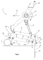
- Fig. 1 shows a tillage device 1 in side view.
- the tillage device 1 has wheels 4 and a coupling device, not shown, which is connected to the machine frame 20.
- the coupling device By means of the coupling device, the tillage device 1 with a towing vehicle be coupled and pulled with the towing vehicle.
- the tilling device 1 may also be self-propelled.
- the soil cultivation device 1 has a machine frame 20. Furthermore, the soil cultivation device 1 has a drive 6, and at least one of the drive 6 movable up and down on the machine frame 20 pivotally mounted support arm 10.
- the support arm 10 is driven via the push rod 8 by means of the drive 6.
- the support arm 10 is pivotally mounted at a first end about a pivot axis 42 on the machine frame 20.
- the push rod 8 is connected via a hinge 44 with the support arm 10.
- the drive 6 is a crank drive in the illustrated embodiment.
- the drive 6 drives the push rod 8, which in turn drives the support arm 10, so that it is moved up and down and thereby pivoted about the pivot axis 42.
- a tool holder 26 is pivotally mounted about a first pivot axis 24.
- At least one piercing tool 28, preferably a plurality of piercing tools 28, is connected to the tool holder 26.
- the piercing tools 28 can be connected to the tool holder 26 by means of the fastening device 30.
- the at least one piercing tool 28 is thus coupled to the support arm 10 and can pivot relative to the support arm 10. Further, the at least one piercing tool 28 can be moved up and down by means of the support arm 10, wherein the piercing tool 28 in the bottom 2 pierceable and pulled out again.
- the soil cultivation device 1 has at least one return device 12, which is coupled to the machine frame 20 at a first end 12a and is coupled to the piercing tool 28 at a second end 12b.
- the return device 12 is coupled at the first end 12a via an adjusting device 18 to the machine frame 20, wherein the return device 12 is pivotally coupled to the adjusting device via the pivot axis 16.
- the return device 12 is connected via a pivot axis 14 with the tool holder 26 and thus coupled to the at least one piercing tool 28.
- Fig. 1 is shown an operating state in which the piercing tool 28 is located shortly before piercing the ground. Before piercing the soil, the piercing tool 28 is in a starting position at a predetermined piercing angle a. When the support arm 10 is pivoted down by means of the drive 6, the piercing tool 28 pierces the ground. This condition is in Fig. 2 shown. In the bottom 2, the piercing tool 28, due to the movement of the machine frame 20 in the direction of travel A, performs a pivotal movement about the first pivot axis 24 in the direction of a first pivoting direction 42, superimposed on the up and down motion.
- Fig. 3 the state is shown in which the piercing tool has been pivoted in the direction of the first pivoting direction 42 and has been moved up again by means of the drive 6.
- the return device 12 has at least one return element, which transfers the piercing tool 28 after exiting the bottom 2 into the starting position by pivoting the piercing tool about the first pivot axis 24 in a first pivot direction 42 opposite the second pivot direction 43.
- the return device 12 may be a piston-cylinder unit in the illustrated embodiment.
- the return device 12 has a piston rod 32, which emerges from the cylinder unit 34 during pivoting in the first pivoting direction 42.
- the return device 12 is thus variable in length.
- the retractor 12 is preferably arranged substantially parallel to the support arm 10, whereby the retractor 12 and the support arm 10 have a parallelogram-like arrangement.
- the return device 12 may have, in addition to the return element, a spring device which allows pivoting of the piercing tool 28 in the second pivoting direction 43 beyond the initial position, so that the Lancing tool when hitting a hard object in the bottom 2, such as a stone 50, by pivoting the piercing tool 28 in the second pivoting direction 43 beyond the initial position is also pivotable.
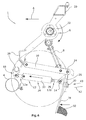
- a condition is shown in which the piercing tool 28 strikes a hard object such as a stone 50.
- the piercing tool 28 can now pivot further in the direction of the second pivoting direction 43, whereby the piston rod 32 is further inserted into the cylinder unit 34.
- the piercing tool 28 can thus, as in Fig. 4 shown dodge the hard object 50.
- the spring device 52 can move the piercing tool back to the starting position.
- the return device 12 has a return element 54, by means of which the piercing tool is transferred after exiting from the ground back into the starting position by pivoting the piercing tool 28 in the second pivot direction 43 opposite the first pivot direction.
- the return element 54 is a spring, preferably a compression spring.
- the illustrated return device 12 is a piston-cylinder unit. This consists of a piston rod 32 and a cylinder unit 34.
- the cylinder unit 34 has a first outer cylinder 33 and an inner cylinder 35.
- the return member 54 is disposed in the inner cylinder 35.
- the piston rod 32 can be reciprocated within the inner cylinder 35.
- Fig. 5 the piston-cylinder unit is shown in the starting position.
- Fig. 6 the piston-cylinder unit is shown with the piston rod 32 pulled out.
- the return element 54 which consists of a compression spring, is compressed within the inner cylinder 35.
- the piston rod 32 is pulled out against the spring force of the return member 54 from the inner cylinder 35 and thus from the cylinder unit 34 and this allows the piercing tool 28 in the movement in the direction of travel A in the direction of the first pivoting direction 42 to pivot.
- the piston rod 32 is again inserted in the cylinder unit 34 and thus in the inner cylinder 35, which causes the piercing tool 28 to move in the direction of the second pivoting direction 43 pivoted about the pivot axis 24 back to the starting position.
- the free end 32a of the piston rod 32 strikes the stop member 58 and the movement of the piston rod 32 is limited.
- the spring device 52 With the inner cylinder 35, the spring device 52 is coupled.
- the spring device 52 is biased with a certain biasing force. Only when a predetermined force acts on the piercing tool 28 and the piercing tool pivots in the direction of the second pivot axis 42 and the piston rod rests against the stop 58, the spring device 52 is compressed. This means that the spring force of the spring device 52 is selected such that the spring device 52 only permits the movement of the piercing tool 28 beyond the starting position when a force is exerted on the piercing tool 28 which exceeds a predetermined force.
- the biasing force and thus the spring force of the spring device can be adjustable.
- the piston rod 32 can be further inserted into the cylinder unit 34 against the spring force of the spring means 52, wherein the inner cylinder 35 is moved in the outer cylinder 33 in the direction of the second pivoting direction 43.
- the projection 59 of the inner cylinder 35 presses against the spring 52.
- the return element 54 and the spring device 52 thus act on the piercing tool 28 in different directions.
- the return element 54 causes the piercing tool 28, after pivoting in the ground and leaving the ground, to move again in the second pivoting direction 43 in the direction of the starting position.
- the spring device 52 causes, after the piercing tool has pivoted on the basis of the impact on a hard object in the ground beyond the initial position in the second pivoting direction 43, that the piercing tool 28 moves back in the direction of the first pivoting direction 42 back into the starting position as soon as the piercing tool 28 has exited from the bottom 2.
- a plurality of support arms may be arranged side by side, which are each connected to a tool holder, wherein each tool holder is associated with a return device. With each tool holder, one or more piercing tools can be connected.
- the present invention has the advantage that, if only one piercing tool of a tool holder strikes a hard object, only the piercing tools associated with the toolholder, due to the spring device in the retracting device, dodge the object. The remaining lancing tools on the other tool holders can continue to be operated normally.
- an adjusting device 18 is shown, which is pivotable relative to the machine frame 20.
- the pivot axis 16 can be pivoted relative to the machine frame 20, whereby the return device 12 and thus the tool holder 26 and the piercing tools 28 can be adjusted.
- the piercing angle a can be set in the starting position.
- the adjusting device 18 can be adjusted simultaneously for all juxtaposed units of tool holder, piercing tools and restoring device.
- the return device can also be connected directly pivotally connected to the machine frame.
Landscapes
- Life Sciences & Earth Sciences (AREA)
- Engineering & Computer Science (AREA)
- Mechanical Engineering (AREA)
- Soil Sciences (AREA)
- Environmental Sciences (AREA)
- Soil Working Implements (AREA)
- Agricultural Machines (AREA)
Priority Applications (5)
| Application Number | Priority Date | Filing Date | Title |
|---|---|---|---|
| HUE14168659A HUE041767T2 (hu) | 2014-05-16 | 2014-05-16 | Talajmegmunkáló eszköz |
| EP14168659.2A EP2944167B1 (fr) | 2014-05-16 | 2014-05-16 | Dispositif de traitement de sol |
| PCT/EP2015/060900 WO2015173431A1 (fr) | 2014-05-16 | 2015-05-18 | Dispositif de travail du sol |
| US15/311,565 US10362722B2 (en) | 2014-05-16 | 2015-05-18 | Soil processing device |
| CA2949302A CA2949302C (fr) | 2014-05-16 | 2015-05-18 | Dispositif de travail du sol |
Applications Claiming Priority (1)
| Application Number | Priority Date | Filing Date | Title |
|---|---|---|---|
| EP14168659.2A EP2944167B1 (fr) | 2014-05-16 | 2014-05-16 | Dispositif de traitement de sol |
Publications (2)
| Publication Number | Publication Date |
|---|---|
| EP2944167A1 true EP2944167A1 (fr) | 2015-11-18 |
| EP2944167B1 EP2944167B1 (fr) | 2018-11-28 |
Family
ID=50729391
Family Applications (1)
| Application Number | Title | Priority Date | Filing Date |
|---|---|---|---|
| EP14168659.2A Active EP2944167B1 (fr) | 2014-05-16 | 2014-05-16 | Dispositif de traitement de sol |
Country Status (5)
| Country | Link |
|---|---|
| US (1) | US10362722B2 (fr) |
| EP (1) | EP2944167B1 (fr) |
| CA (1) | CA2949302C (fr) |
| HU (1) | HUE041767T2 (fr) |
| WO (1) | WO2015173431A1 (fr) |
Families Citing this family (1)
| Publication number | Priority date | Publication date | Assignee | Title |
|---|---|---|---|---|
| US11665988B2 (en) * | 2019-02-22 | 2023-06-06 | Briggs & Stratton, Llc | Stand-on outdoor power equipment for aerating soil |
Citations (5)
| Publication number | Priority date | Publication date | Assignee | Title |
|---|---|---|---|---|
| EP0037595A1 (fr) | 1980-03-10 | 1981-10-14 | Redexim Holding S.A. | Appareil pour la confection de drains verticaux dans des pelouses, des champs, des prairies etc. |
| DE102005021025A1 (de) * | 2005-04-01 | 2006-10-05 | Wiedenmann Gmbh | Bodenbearbeitungsgerät |
| EP2014146A1 (fr) * | 2007-07-12 | 2009-01-14 | Redexim Handel-en Exploitatie Maatschappij B.V. | Dispositif de traitement de sol |
| EP2106679A1 (fr) * | 2008-04-01 | 2009-10-07 | Redexim Handel-en Exploitatie Maatschappij B.V. | Dispositif d'aération au sol |
| EP2123143A1 (fr) * | 2008-05-23 | 2009-11-25 | Redexim Handel-en Exploitatie Maatschappij B.V. | Dispositif d'aération du sol et procédé pour enfoncer des outils de pénétration dans le sol |
Family Cites Families (7)
| Publication number | Priority date | Publication date | Assignee | Title |
|---|---|---|---|---|
| US3797577A (en) * | 1972-06-13 | 1974-03-19 | R Williams | Turf perforating tool |
| EP0195103B1 (fr) * | 1985-03-20 | 1989-10-11 | Greencare Pty. Limited | Scarificateur |
| NL1004926C2 (nl) * | 1997-01-03 | 1998-07-06 | Redexim Handel En Expl Mij Bv | Inrichting voor het beluchten van een bodemlaag. |
| US5787992A (en) * | 1997-03-06 | 1998-08-04 | Morris Industries Ltd. | Spring tip shank assembly having quick-dropping trip-out force and improved resetting ability |
| EP1967055A1 (fr) * | 2007-03-06 | 2008-09-10 | Redexim Handel-en Exploitatie Maatschappij B.V. | Dispositif de traitement de sol |
| DE202012010495U1 (de) * | 2012-11-05 | 2014-02-14 | Redexim Handel- En Exploitatie Maatschappij B.V. | Bodenbearbeitungsvorrichtung zum Erzeugen von Hohlräumen in einem Boden |
| HUE050020T2 (hu) * | 2012-12-21 | 2020-11-30 | Redexim Handel En Exploitatie Mij B V | Talajmegmunkáló szerkezet talajfelületek megmunkálására, valamint eljárás talajfelületek megmunkálására |
-
2014
- 2014-05-16 EP EP14168659.2A patent/EP2944167B1/fr active Active
- 2014-05-16 HU HUE14168659A patent/HUE041767T2/hu unknown
-
2015
- 2015-05-18 CA CA2949302A patent/CA2949302C/fr active Active
- 2015-05-18 US US15/311,565 patent/US10362722B2/en active Active
- 2015-05-18 WO PCT/EP2015/060900 patent/WO2015173431A1/fr not_active Ceased
Patent Citations (5)
| Publication number | Priority date | Publication date | Assignee | Title |
|---|---|---|---|---|
| EP0037595A1 (fr) | 1980-03-10 | 1981-10-14 | Redexim Holding S.A. | Appareil pour la confection de drains verticaux dans des pelouses, des champs, des prairies etc. |
| DE102005021025A1 (de) * | 2005-04-01 | 2006-10-05 | Wiedenmann Gmbh | Bodenbearbeitungsgerät |
| EP2014146A1 (fr) * | 2007-07-12 | 2009-01-14 | Redexim Handel-en Exploitatie Maatschappij B.V. | Dispositif de traitement de sol |
| EP2106679A1 (fr) * | 2008-04-01 | 2009-10-07 | Redexim Handel-en Exploitatie Maatschappij B.V. | Dispositif d'aération au sol |
| EP2123143A1 (fr) * | 2008-05-23 | 2009-11-25 | Redexim Handel-en Exploitatie Maatschappij B.V. | Dispositif d'aération du sol et procédé pour enfoncer des outils de pénétration dans le sol |
Also Published As
| Publication number | Publication date |
|---|---|
| HUE041767T2 (hu) | 2019-05-28 |
| US20170094888A1 (en) | 2017-04-06 |
| EP2944167B1 (fr) | 2018-11-28 |
| CA2949302C (fr) | 2023-04-11 |
| US10362722B2 (en) | 2019-07-30 |
| WO2015173431A1 (fr) | 2015-11-19 |
| CA2949302A1 (fr) | 2015-11-19 |
Similar Documents
| Publication | Publication Date | Title |
|---|---|---|
| EP2745665B1 (fr) | Dispositif de traitement de sol destiné à travailler les surfaces de sol ainsi que procédé de traitement de surfaces de sol | |
| DE2801116A1 (de) | Klappbarer geraetetraeger mit zwei werkzeugtragrahmen | |
| EP1967056A1 (fr) | Dispositif de traitement de sol | |
| EP0924975B1 (fr) | Outil pour ameublir le sol en profondeur | |
| DE112013001318T5 (de) | Geräterahmen mit nach vorne faltbaren Flügeln | |
| EP2014146B1 (fr) | Dispositif de traitement de sol | |
| EP2754343B1 (fr) | Dispositif de traitement de sol mobile avec dispositif de protection | |
| EP3401444A1 (fr) | Dispositif d'excavation de tranchée et procédé de fabrication de tranchées dans le sol | |
| DE69101215T2 (de) | Verriegelungsvorrichtung einer schwenkbaren Radhalterung. | |
| EP1951024B1 (fr) | Appareil de traitement du sol dote d'une protection de manivelle | |
| DE1900762A1 (de) | UEberlastungssicherung fuer Bodenbearbeitungswerkzeuge,insbesondere Pfluege,Eggen od.dgl. | |
| EP2944167B1 (fr) | Dispositif de traitement de sol | |
| EP2914083B1 (fr) | Dispositif de travail du sol pour réaliser des cavités dans un sol | |
| EP1859665A1 (fr) | Machine agricole tractée à grande largeur de travail | |
| EP4166719B1 (fr) | Machine de construction | |
| DE102017110775A1 (de) | Saugfußanordnung für eine Bodenreinigungsmaschine | |
| DE19630961C2 (de) | Bearbeitungsgerät für die Tiefenlockerung von Böden | |
| DE102016120620A1 (de) | Bodenbearbeitungsmaschine | |
| DE1634776A1 (de) | Vorrichtung zum Verschieben,beispielsweise Seitenverschieben,eines mit einer Baumaschine,beispielsweise einem Strassenhobel,verbindbaren Arbeitswerkzeuges,insbesondere Planierschars | |
| EP2965607B1 (fr) | Semoir | |
| DE2538883A1 (de) | Drehpflug | |
| EP2997803B1 (fr) | Outillage agricole | |
| AT397594B (de) | Steinsicherungsvorrichtung für drehpflüge | |
| EP3545736B1 (fr) | Machine de travail du sol | |
| EP4173457A1 (fr) | Agencement doté d'un outil de travail destiné au traitement du sol pour une machine agricole, ainsi que machine agricole |
Legal Events
| Date | Code | Title | Description |
|---|---|---|---|
| PUAI | Public reference made under article 153(3) epc to a published international application that has entered the european phase |
Free format text: ORIGINAL CODE: 0009012 |
|
| AK | Designated contracting states |
Kind code of ref document: A1 Designated state(s): AL AT BE BG CH CY CZ DE DK EE ES FI FR GB GR HR HU IE IS IT LI LT LU LV MC MK MT NL NO PL PT RO RS SE SI SK SM TR |
|
| AX | Request for extension of the european patent |
Extension state: BA ME |
|
| 17P | Request for examination filed |
Effective date: 20160518 |
|
| RBV | Designated contracting states (corrected) |
Designated state(s): AL AT BE BG CH CY CZ DE DK EE ES FI FR GB GR HR HU IE IS IT LI LT LU LV MC MK MT NL NO PL PT RO RS SE SI SK SM TR |
|
| GRAP | Despatch of communication of intention to grant a patent |
Free format text: ORIGINAL CODE: EPIDOSNIGR1 |
|
| STAA | Information on the status of an ep patent application or granted ep patent |
Free format text: STATUS: GRANT OF PATENT IS INTENDED |
|
| RAP1 | Party data changed (applicant data changed or rights of an application transferred) |
Owner name: REDEXIM HANDEL- EN EXPLOITATIE MAATSCHAPPIJ B.V. |
|
| INTG | Intention to grant announced |
Effective date: 20180615 |
|
| RIN1 | Information on inventor provided before grant (corrected) |
Inventor name: DE BREE, CORNELIUS HERMANUS MARIA |
|
| GRAS | Grant fee paid |
Free format text: ORIGINAL CODE: EPIDOSNIGR3 |
|
| GRAA | (expected) grant |
Free format text: ORIGINAL CODE: 0009210 |
|
| STAA | Information on the status of an ep patent application or granted ep patent |
Free format text: STATUS: THE PATENT HAS BEEN GRANTED |
|
| AK | Designated contracting states |
Kind code of ref document: B1 Designated state(s): AL AT BE BG CH CY CZ DE DK EE ES FI FR GB GR HR HU IE IS IT LI LT LU LV MC MK MT NL NO PL PT RO RS SE SI SK SM TR |
|
| REG | Reference to a national code |
Ref country code: CH Ref legal event code: EP |
|
| REG | Reference to a national code |
Ref country code: AT Ref legal event code: REF Ref document number: 1069117 Country of ref document: AT Kind code of ref document: T Effective date: 20181215 |
|
| REG | Reference to a national code |
Ref country code: DE Ref legal event code: R096 Ref document number: 502014010186 Country of ref document: DE |
|
| REG | Reference to a national code |
Ref country code: IE Ref legal event code: FG4D Free format text: LANGUAGE OF EP DOCUMENT: GERMAN |
|
| REG | Reference to a national code |
Ref country code: NL Ref legal event code: FP |
|
| REG | Reference to a national code |
Ref country code: LT Ref legal event code: MG4D |
|
| PG25 | Lapsed in a contracting state [announced via postgrant information from national office to epo] |
Ref country code: LV Free format text: LAPSE BECAUSE OF FAILURE TO SUBMIT A TRANSLATION OF THE DESCRIPTION OR TO PAY THE FEE WITHIN THE PRESCRIBED TIME-LIMIT Effective date: 20181128 Ref country code: FI Free format text: LAPSE BECAUSE OF FAILURE TO SUBMIT A TRANSLATION OF THE DESCRIPTION OR TO PAY THE FEE WITHIN THE PRESCRIBED TIME-LIMIT Effective date: 20181128 Ref country code: BG Free format text: LAPSE BECAUSE OF FAILURE TO SUBMIT A TRANSLATION OF THE DESCRIPTION OR TO PAY THE FEE WITHIN THE PRESCRIBED TIME-LIMIT Effective date: 20190228 Ref country code: LT Free format text: LAPSE BECAUSE OF FAILURE TO SUBMIT A TRANSLATION OF THE DESCRIPTION OR TO PAY THE FEE WITHIN THE PRESCRIBED TIME-LIMIT Effective date: 20181128 Ref country code: HR Free format text: LAPSE BECAUSE OF FAILURE TO SUBMIT A TRANSLATION OF THE DESCRIPTION OR TO PAY THE FEE WITHIN THE PRESCRIBED TIME-LIMIT Effective date: 20181128 Ref country code: NO Free format text: LAPSE BECAUSE OF FAILURE TO SUBMIT A TRANSLATION OF THE DESCRIPTION OR TO PAY THE FEE WITHIN THE PRESCRIBED TIME-LIMIT Effective date: 20190228 Ref country code: ES Free format text: LAPSE BECAUSE OF FAILURE TO SUBMIT A TRANSLATION OF THE DESCRIPTION OR TO PAY THE FEE WITHIN THE PRESCRIBED TIME-LIMIT Effective date: 20181128 Ref country code: IS Free format text: LAPSE BECAUSE OF FAILURE TO SUBMIT A TRANSLATION OF THE DESCRIPTION OR TO PAY THE FEE WITHIN THE PRESCRIBED TIME-LIMIT Effective date: 20190328 |
|
| REG | Reference to a national code |
Ref country code: HU Ref legal event code: AG4A Ref document number: E041767 Country of ref document: HU |
|
| PG25 | Lapsed in a contracting state [announced via postgrant information from national office to epo] |
Ref country code: PT Free format text: LAPSE BECAUSE OF FAILURE TO SUBMIT A TRANSLATION OF THE DESCRIPTION OR TO PAY THE FEE WITHIN THE PRESCRIBED TIME-LIMIT Effective date: 20190328 Ref country code: GR Free format text: LAPSE BECAUSE OF FAILURE TO SUBMIT A TRANSLATION OF THE DESCRIPTION OR TO PAY THE FEE WITHIN THE PRESCRIBED TIME-LIMIT Effective date: 20190301 Ref country code: AL Free format text: LAPSE BECAUSE OF FAILURE TO SUBMIT A TRANSLATION OF THE DESCRIPTION OR TO PAY THE FEE WITHIN THE PRESCRIBED TIME-LIMIT Effective date: 20181128 Ref country code: SE Free format text: LAPSE BECAUSE OF FAILURE TO SUBMIT A TRANSLATION OF THE DESCRIPTION OR TO PAY THE FEE WITHIN THE PRESCRIBED TIME-LIMIT Effective date: 20181128 Ref country code: RS Free format text: LAPSE BECAUSE OF FAILURE TO SUBMIT A TRANSLATION OF THE DESCRIPTION OR TO PAY THE FEE WITHIN THE PRESCRIBED TIME-LIMIT Effective date: 20181128 |
|
| PG25 | Lapsed in a contracting state [announced via postgrant information from national office to epo] |
Ref country code: CZ Free format text: LAPSE BECAUSE OF FAILURE TO SUBMIT A TRANSLATION OF THE DESCRIPTION OR TO PAY THE FEE WITHIN THE PRESCRIBED TIME-LIMIT Effective date: 20181128 Ref country code: DK Free format text: LAPSE BECAUSE OF FAILURE TO SUBMIT A TRANSLATION OF THE DESCRIPTION OR TO PAY THE FEE WITHIN THE PRESCRIBED TIME-LIMIT Effective date: 20181128 Ref country code: PL Free format text: LAPSE BECAUSE OF FAILURE TO SUBMIT A TRANSLATION OF THE DESCRIPTION OR TO PAY THE FEE WITHIN THE PRESCRIBED TIME-LIMIT Effective date: 20181128 |
|
| REG | Reference to a national code |
Ref country code: DE Ref legal event code: R097 Ref document number: 502014010186 Country of ref document: DE |
|
| PG25 | Lapsed in a contracting state [announced via postgrant information from national office to epo] |
Ref country code: SK Free format text: LAPSE BECAUSE OF FAILURE TO SUBMIT A TRANSLATION OF THE DESCRIPTION OR TO PAY THE FEE WITHIN THE PRESCRIBED TIME-LIMIT Effective date: 20181128 Ref country code: RO Free format text: LAPSE BECAUSE OF FAILURE TO SUBMIT A TRANSLATION OF THE DESCRIPTION OR TO PAY THE FEE WITHIN THE PRESCRIBED TIME-LIMIT Effective date: 20181128 Ref country code: EE Free format text: LAPSE BECAUSE OF FAILURE TO SUBMIT A TRANSLATION OF THE DESCRIPTION OR TO PAY THE FEE WITHIN THE PRESCRIBED TIME-LIMIT Effective date: 20181128 Ref country code: SM Free format text: LAPSE BECAUSE OF FAILURE TO SUBMIT A TRANSLATION OF THE DESCRIPTION OR TO PAY THE FEE WITHIN THE PRESCRIBED TIME-LIMIT Effective date: 20181128 |
|
| PLBE | No opposition filed within time limit |
Free format text: ORIGINAL CODE: 0009261 |
|
| STAA | Information on the status of an ep patent application or granted ep patent |
Free format text: STATUS: NO OPPOSITION FILED WITHIN TIME LIMIT |
|
| PG25 | Lapsed in a contracting state [announced via postgrant information from national office to epo] |
Ref country code: SI Free format text: LAPSE BECAUSE OF FAILURE TO SUBMIT A TRANSLATION OF THE DESCRIPTION OR TO PAY THE FEE WITHIN THE PRESCRIBED TIME-LIMIT Effective date: 20181128 |
|
| 26N | No opposition filed |
Effective date: 20190829 |
|
| REG | Reference to a national code |
Ref country code: CH Ref legal event code: PL |
|
| PG25 | Lapsed in a contracting state [announced via postgrant information from national office to epo] |
Ref country code: MC Free format text: LAPSE BECAUSE OF FAILURE TO SUBMIT A TRANSLATION OF THE DESCRIPTION OR TO PAY THE FEE WITHIN THE PRESCRIBED TIME-LIMIT Effective date: 20181128 Ref country code: LI Free format text: LAPSE BECAUSE OF NON-PAYMENT OF DUE FEES Effective date: 20190531 Ref country code: CH Free format text: LAPSE BECAUSE OF NON-PAYMENT OF DUE FEES Effective date: 20190531 |
|
| REG | Reference to a national code |
Ref country code: BE Ref legal event code: MM Effective date: 20190531 |
|
| PG25 | Lapsed in a contracting state [announced via postgrant information from national office to epo] |
Ref country code: LU Free format text: LAPSE BECAUSE OF NON-PAYMENT OF DUE FEES Effective date: 20190516 |
|
| PG25 | Lapsed in a contracting state [announced via postgrant information from national office to epo] |
Ref country code: TR Free format text: LAPSE BECAUSE OF FAILURE TO SUBMIT A TRANSLATION OF THE DESCRIPTION OR TO PAY THE FEE WITHIN THE PRESCRIBED TIME-LIMIT Effective date: 20181128 |
|
| PG25 | Lapsed in a contracting state [announced via postgrant information from national office to epo] |
Ref country code: IE Free format text: LAPSE BECAUSE OF NON-PAYMENT OF DUE FEES Effective date: 20190516 |
|
| PG25 | Lapsed in a contracting state [announced via postgrant information from national office to epo] |
Ref country code: BE Free format text: LAPSE BECAUSE OF NON-PAYMENT OF DUE FEES Effective date: 20190531 |
|
| REG | Reference to a national code |
Ref country code: AT Ref legal event code: MM01 Ref document number: 1069117 Country of ref document: AT Kind code of ref document: T Effective date: 20190516 |
|
| PG25 | Lapsed in a contracting state [announced via postgrant information from national office to epo] |
Ref country code: AT Free format text: LAPSE BECAUSE OF NON-PAYMENT OF DUE FEES Effective date: 20190516 |
|
| PG25 | Lapsed in a contracting state [announced via postgrant information from national office to epo] |
Ref country code: CY Free format text: LAPSE BECAUSE OF FAILURE TO SUBMIT A TRANSLATION OF THE DESCRIPTION OR TO PAY THE FEE WITHIN THE PRESCRIBED TIME-LIMIT Effective date: 20181128 |
|
| PG25 | Lapsed in a contracting state [announced via postgrant information from national office to epo] |
Ref country code: MT Free format text: LAPSE BECAUSE OF FAILURE TO SUBMIT A TRANSLATION OF THE DESCRIPTION OR TO PAY THE FEE WITHIN THE PRESCRIBED TIME-LIMIT Effective date: 20181128 |
|
| PG25 | Lapsed in a contracting state [announced via postgrant information from national office to epo] |
Ref country code: MK Free format text: LAPSE BECAUSE OF FAILURE TO SUBMIT A TRANSLATION OF THE DESCRIPTION OR TO PAY THE FEE WITHIN THE PRESCRIBED TIME-LIMIT Effective date: 20181128 |
|
| P01 | Opt-out of the competence of the unified patent court (upc) registered |
Effective date: 20230530 |
|
| PGFP | Annual fee paid to national office [announced via postgrant information from national office to epo] |
Ref country code: NL Payment date: 20250522 Year of fee payment: 12 |
|
| PGFP | Annual fee paid to national office [announced via postgrant information from national office to epo] |
Ref country code: DE Payment date: 20250428 Year of fee payment: 12 |
|
| PGFP | Annual fee paid to national office [announced via postgrant information from national office to epo] |
Ref country code: HU Payment date: 20250512 Year of fee payment: 12 |
|
| PGFP | Annual fee paid to national office [announced via postgrant information from national office to epo] |
Ref country code: IT Payment date: 20250530 Year of fee payment: 12 |
|
| PGFP | Annual fee paid to national office [announced via postgrant information from national office to epo] |
Ref country code: FR Payment date: 20250521 Year of fee payment: 12 |
|
| PGFP | Annual fee paid to national office [announced via postgrant information from national office to epo] |
Ref country code: GB Payment date: 20260327 Year of fee payment: 13 |