EP2944224A1 - Dispositif de retenue pour étagère sur une paroi d'étagère et étagère dotée d'un tel dispositif de retenue - Google Patents
Dispositif de retenue pour étagère sur une paroi d'étagère et étagère dotée d'un tel dispositif de retenue Download PDFInfo
- Publication number
- EP2944224A1 EP2944224A1 EP15167248.2A EP15167248A EP2944224A1 EP 2944224 A1 EP2944224 A1 EP 2944224A1 EP 15167248 A EP15167248 A EP 15167248A EP 2944224 A1 EP2944224 A1 EP 2944224A1
- Authority
- EP
- European Patent Office
- Prior art keywords
- shelf
- holding
- connecting element
- wall
- holding device
- Prior art date
- Legal status (The legal status is an assumption and is not a legal conclusion. Google has not performed a legal analysis and makes no representation as to the accuracy of the status listed.)
- Granted
Links
- 230000006835 compression Effects 0.000 claims description 2
- 238000007906 compression Methods 0.000 claims description 2
- 230000000903 blocking effect Effects 0.000 description 6
- 230000006378 damage Effects 0.000 description 5
- 239000000463 material Substances 0.000 description 5
- XEEYBQQBJWHFJM-UHFFFAOYSA-N Iron Chemical compound [Fe] XEEYBQQBJWHFJM-UHFFFAOYSA-N 0.000 description 4
- 208000027418 Wounds and injury Diseases 0.000 description 4
- 230000001154 acute effect Effects 0.000 description 4
- 230000005540 biological transmission Effects 0.000 description 4
- 208000014674 injury Diseases 0.000 description 4
- 238000004519 manufacturing process Methods 0.000 description 4
- 229910000831 Steel Inorganic materials 0.000 description 3
- 230000005484 gravity Effects 0.000 description 3
- 239000002184 metal Substances 0.000 description 3
- 229910052751 metal Inorganic materials 0.000 description 3
- 239000010959 steel Substances 0.000 description 3
- 239000000853 adhesive Substances 0.000 description 2
- 230000001070 adhesive effect Effects 0.000 description 2
- 230000007423 decrease Effects 0.000 description 2
- 239000006260 foam Substances 0.000 description 2
- 229910052742 iron Inorganic materials 0.000 description 2
- 238000005192 partition Methods 0.000 description 2
- 238000013459 approach Methods 0.000 description 1
- 230000003247 decreasing effect Effects 0.000 description 1
- 230000000694 effects Effects 0.000 description 1
- 230000002349 favourable effect Effects 0.000 description 1
- 238000009434 installation Methods 0.000 description 1
- 230000001404 mediated effect Effects 0.000 description 1
- 230000035515 penetration Effects 0.000 description 1
- 208000008918 voyeurism Diseases 0.000 description 1
- 239000002023 wood Substances 0.000 description 1
Images



Classifications
-
- A—HUMAN NECESSITIES
- A47—FURNITURE; DOMESTIC ARTICLES OR APPLIANCES; COFFEE MILLS; SPICE MILLS; SUCTION CLEANERS IN GENERAL
- A47B—TABLES; DESKS; OFFICE FURNITURE; CABINETS; DRAWERS; GENERAL DETAILS OF FURNITURE
- A47B96/00—Details of cabinets, racks or shelf units not covered by a single one of groups A47B43/00 - A47B95/00; General details of furniture
- A47B96/06—Brackets or similar supporting means for cabinets, racks or shelves
- A47B96/066—Supporting means received within an edge of the shelf
Definitions
- the invention relates to a holding device for a shelf on a shelf wall, a shelf according to the preamble of claim 12 and the use of the holding device in a piece of furniture according to claim 17.
- the object of the invention is therefore to enable a simple and quick adjustment of the height of the shelves in a shelf.
- a safe and aesthetically pleasing shelf should be created.
- the fixture should also be used in pieces of furniture for holding appropriate furniture parts.
- the holding device according to the invention for a shelf on a shelf wall is characterized in that it comprises a to be arranged in the shelf wall first connecting element still a to be arranged in the shelf second connecting element, and at least one of the connecting elements has an attracting to the respective other connecting element acting magnet.
- a holding element of the first connecting element can be moved magnetically from a retracted retraction position into an extended holding position for holding the shelf. Due to the magnetic attraction between the connecting elements, an automatic extension holding element of the first connecting element into the holding position is made possible as soon as the connecting elements come into magnetically effective proximity, so that no additional working step is required for this.
- first connecting elements are provided at different heights in the rack walls, then only those holding elements in the immediate vicinity of which there is a shelf with corresponding second connecting elements are in the extended holding position.
- the retaining elements of the remaining first connecting elements are in a retracted position, which avoids injuries and allows an aesthetic impression of the inside of the shelf walls.
- the first connecting element may comprise a spring element or a further magnetic element.
- the spring element can be designed as a preferably helical compression spring around the holding element around and be supported on the one hand at an area with increased cross section of the holding element and on the other hand on a securing element of the first connecting element to hold the holding element in the retracted retracted position. It is also possible to carry out the spring element as a tension spring, which is connected to the holding element and the shelf wall, so as to pull the holding element in the retracted retracted position.
- the spring element can be dimensioned so that in the retracted retracted position of the retaining element, the spring element is enstpannt. Only when the retaining element is moved out of this retracted position, the spring element is biased. This ensures that the magnetic force to move the holding element extremely low can.
- the spring element in addition to the usual spiral design made of metal or plastic and a foam with appropriate stretch or compressibility consist, for example, a hollow cylinder or a spiral of foam.
- this may further comprise a securing element.
- this securing element is designed as a socket for receiving and guiding the holding element.
- the bushing is designed so that, although the retaining element can be received and guided therein, however, the region of the enlarged cross section of the retaining element can not pass through the socket.
- the retaining element preferably has a region with an enlarged cross section for securing to the first connecting element. This prevents that the holding element unintentionally detached from the first connecting element and falls out of the shelf wall.
- the region with increased cross-section can be arranged centrally or at a rear end opposite the protruding end of the retaining element.
- the holding element can be designed so that it protrudes in the extended holding position only on an inner side of the respective shelf wall. This is the case, for example, with the outer shelf walls of a shelf. Then, the area of the enlarged cross section is located at the rear end.
- first connecting elements are to be provided on both sides in these intermediate walls, but this can be achieved particularly advantageously by arranging the holding element of each first connecting element in a through hole in the intermediate wall, that it can protrude from both side surfaces of the intermediate wall.
- the region of the enlarged cross section is preferably arranged centrally on the holding element.
- the securing element may have a first section whose inner contour is slightly larger than the outer contour of the retaining element, and a second section whose inner contour is slightly larger than the outer contour of the area with enlarged Cross-section of the retaining element is, have.
- the guidance of the retaining element in the securing element can be improved, since the retaining element is guided completely in the securing element.
- an obliquely inserted into the shelf wall securing element does not affect the function of the pull-out support member, since the latter can not tilt on a wall of the shelf wall and get stuck.
- the cross section of the inner contour of this securing element and the corresponding cross section of the outer contour of the holding element can be formed, for example, rectangular.
- the holding element at a front, the shelf-facing end having a blocking element, wherein the cross section in the region of its free end is the largest.
- the locking element in the extended holding position engage behind a corresponding undercut on the shelf and thus secure the first connecting element to the shelf.
- the region of the free end of the retaining element is preferably that region which protrudes from the shelf wall in the extended holding position of the retaining element.
- the holding element may be formed as an elongated retaining pin. But it is also possible to carry out the holding element, for example, as an elongated strip, whereby a particularly large-scale power transmission between the shelf and the shelf wall is made possible. Other configurations of the retaining element, for example with different cross sections or thicknesses are possible.
- a shelf has at least one holding device described above and below as well as at least two shelf walls and at least one shelf.
- the second connecting element of the holding device is on a shelf wall facing the end of one of the shelves and the first connecting element of the holding device in the corresponding shelf wall opposite the second connecting element.
- the first connecting element in the shelf wall such that the holding element is movable substantially in a horizontal plane between the holding position and the retracted position.
- the holding element of the second connecting element can also be moved without the influence of gravity.
- the first connecting element is to be arranged in the shelf wall, that the holding element is arranged higher in the holding position than in the retracted position.
- the recess for the first connecting element relative to the shelf wall has an acute angle, which can be achieved for example by oblique holes.
- the spring element or the additional magnetic elements of the holding device which has a favorable effect on the life and the manufacturing cost.
- the described holding element for holding corresponding furniture parts in a piece of furniture.
- These furniture parts can be trays of any kind, for example, floors in a desk, in a cabinet to a slatted base in a bed frame.
- the shelf or the side walls of a shelf box which are attached to the shelf at the lateral ends and parallel to the shelf walls extend, at least one additional magnetic element having, which corresponds in the installed position of the shelf or the shelf box between the shelf walls with at least one further additional magnetic element in one of the shelf walls, in particular correspondingly positioned opposite each other, so that they are in magnetically acting attraction ,
- these additional magnetic elements come in magnetically effective proximity to each other and support the exact positioning of the shelf or the shelf box between the shelf walls by the increasingly strong with reducing the distance between them magnetic force.
- the shelf or the shelf box can be easily and quickly brought into its correct position between the shelf walls, whereby the connecting elements are positioned more easily to each other and thus the automatic extension of the holding elements is facilitated.
- these additional magnetic elements connect the shelf or the side walls of a shelf box with the shelf walls horizontally, whereby the cohesion of these components is enhanced.
- the additional magnetic elements in the shelf or the side walls of a shelf box and the shelf wall are vertically offset from each other so that the additional magnetic element in the shelf or the shelf box in the installed position of the shelf or the shelf box, so if the shelf or the shelf box are supported by the holding device, is arranged slightly above the other additional magnetic element in the shelf wall in the vertical direction.
- the contact pressure of the shelf or the shelf box is increased to the holding device and in particular the holding element, which increases the stability of the shelf.
- the additional magnetic element in the shelf or the shelf box is formed integrally with the magnetically executed second connecting element.
- This combined magnetic element would then be advantageous to arrange so that the magnetic force acts substantially horizontally, so that both the additional additional magnetic element in the shelf wall and the first connecting element come into magnetically effective range, so that on the one hand between the combined magnetic element and the first connecting element has sufficient force to extend the holding element of the first connecting element and on the other hand, the magnetic force between the combined magnetic element and the additional additional magnetic element causes the positioning and pressing force described above.
- the retaining element may be magnetically formed only at its outer, for example, cylindrical with a smaller diameter end.
- the additional additional magnetic element can also be made significantly smaller, in particular have a smaller diameter. This can also be used in the embodiments described above and below.
- the shelf or the shelf box In order to position the shelf or the shelf box in a unique, predetermined position between the shelf walls easier and to avoid incorrect positioning, e.g. that the shelf or the shelf box can be installed rotated 180 ° about the vertical axis, it can be provided that arranged asymmetrically, for example, the additional magnetic elements in the shelf or the shelf box and in the shelf walls in a side view of the shelf or the shelf box are or only one side corresponding magnetic elements in the shelf or the shelf box and the shelf wall are arranged. In case of incorrect installation of the shelf or the shelf box between the shelf walls then acts due to the large distance between the corresponding additional magnetic elements no sufficient magnetic force, whereupon the user detects the missing positioning aid and repositioning.
- the retaining element may consist of a material which is light but nevertheless magnetically active in comparison to steel and / or hollow or perforated.
- the inertia of the holding element can be reduced without thereby appreciably reducing the magnetic force on the holding element. So it is sufficient already a lower magnetic force to bring the holding element in its connection position.
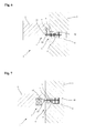
- Fig. 1 shows a sectional view of a first embodiment of the holding device 1 according to the invention used in a shelf 2 and a spaced-apart shelf wall 3 of the invention, only partially shown shelf. This relative position of the shelf 2 to the shelf wall 3 illustrates the situation in which the shelf 2 has not yet been inserted into the shelf.
- the holding device 1 according to the invention comprises a first connecting element 4 and a second connecting element 5.
- the second connecting element 5 is designed as a magnet and inserted from below on the shelf wall 3 facing the end of the shelf 2 flush in a recess in the shelf 2.
- the first connecting element 4 is arranged in a bore formed as a lateral recess 6.
- This comprises a retaining element in the form of an elongated retaining pin 7, a spring element 8 designed as a spiral spring and a securing element 9.
- the retaining pin 7 consists wholly or partly of a magnetically active, that is attractable material, e.g. Steel, iron, etc.
- the securing element 9 is designed as a bush whose inner diameter substantially corresponds to the diameter of the retaining pin 7, so that the securing element 9 can receive and guide the retaining pin 7.
- For fastening of the securing element 9 in the shelf wall 3 is provided to fix this via an adhesive connection, a press connection, a threaded connection or the like flush with the side surface of the shelf wall 3 in the recess 6.
- the retaining pin 7 is designed to be movable relative to the securing element 9.
- the recess 6 corresponds in depth preferably at least the length of the retaining pin 7, so that the retaining pin 7 in a retracted retracted position with its outer, pointing in the direction of the shelf 2 end flush with the side surface of the shelf wall. 3 concludes, definitely not beyond it. Since in this retreat position no part protrudes and the impression of a closed side surface of the shelf wall 3 is mediated, there is no risk of injury and there is an aesthetically pleasing uninterrupted side surface of the shelf wall 3. Ggf the fuse element 9 but also a projecting beyond the shelf wall 3 flange or stop in which case the retaining pin 7 preferably does not project beyond it.
- an area with an enlarged cross-section 10 is formed at the end of the holding pin 7 which points into the recess 6, an area with an enlarged cross-section 10 is formed.
- the diameter of the area with an enlarged cross-section 10 is greater than the inner diameter of the locking element 9 designed as a socket, so that the retaining pin 7 can not pass completely through the securing element 9 and can fall out of the recess 6 of the shelf wall.
- the spring element 8 designed as a spiral spring is arranged around the retaining pin 7.
- the spring element 8 is biased at one end to the region of enlarged cross-section 10 and at the other end to the securing element 9, so that the retaining pin 7 of the first connecting element 4 is held in the retracted retracted position.
- FIG. 2 is a sectional view of the first embodiment of Fig. 1 shown, wherein in this relative position of the shelf 2 to the shelf wall 3 of the shelf 2 is inserted into the shelf. Due to the proximity of the second connecting element 5 designed as a magnet to the first connecting element 4, a magnetic force acts between the connecting elements 4 and 5, which is greater than the retaining force by the spring element 8, so that the retaining pin 7 is in an extended holding position. In this holding position, the retaining pin 7 is acted upon by the magnet of the second connecting element 5 against the action of the spring element 8, whereby the retaining pin 7 protrudes from the side surface of the shelf wall 3 and forms a support for the shelf 2.
- the second connecting element 5 designed as a magnet to the first connecting element 4
- a magnetic force acts between the connecting elements 4 and 5 which is greater than the retaining force by the spring element 8, so that the retaining pin 7 is in an extended holding position.
- the retaining pin 7 is acted upon by the magnet of the second connecting element 5 against the action of the spring element 8, whereby
- Fig. 2a is a modified embodiment of Fig. 2 shown, in which an alternative securing element 9a is provided, which differs from the securing element 9 FIG. 2 over the entire length of the recess 6 in the Shelf wall 3 extends.
- the other components correspond to those from the Figures 1 and 2 and are accordingly provided with the same reference numerals.
- the alternative securing element 9a has a first section, the inner contour of which, as in the case of the securing element 9, essentially corresponds to the outer contour of the retaining pin 7, so that the alternative securing element 9a can receive and guide the retaining pin 7.
- the alternative securing element 9a has a second section, which preferably directly adjoins the first section and has an inner contour which is larger than the inner contour of the first section.
- the inner contour of the second portion substantially corresponds to the outer contour of the enlarged cross-section area 10 of the retaining pin 7. As a result, the region of enlarged cross-section 10 of the retaining pin 7 is received and guided on the inside of the alternative securing element 9a.
- the alternative securing element 9a Due to the narrow dimensional tolerances with which the alternative securing element 9a can be manufactured, and a suitable choice of material for the securing element 9a, for example plastic or metal, which allows compared to a for example made of wood materials shelf wall 3 much more precise production and low friction coefficients, can Tilting of the retaining pin 7 reliably prevented and the operation of the retaining pin between the retracted retracted position and the extended holding position can be further improved.
- the outer contour of the securing element 9a is identical in the first and second sections and essentially corresponds to the inner contour of the recess 6 in the shelf wall 3.
- an adhesive connection is provided for fastening the alternative securing element 9a in the shelf wall 3, as with the securing element 9, that via an adhesive connection.
- a press connection, a threaded connection or the like to fasten flush with the side surface of the shelf wall 3 in the recess 6.
- the securing element 9a is here preferably designed as a cylindrical bushing, wherein the second section with the enlarged inner contour, here inner diameter, by a blind hole and the first portion through the blind hole bottom with the bore with the smaller inner contour, ie here inner diameter of the bore formed ,
- contours or cross sections may advantageously also be used, for example polygonal, in particular triangular, quadrangular, hexagonal or octagonal.
- Fig. 3 a sectional view of a second embodiment of the holding device 1 according to the invention is shown.
- the first embodiment which is also designed as a magnet second connecting element 5 of the shelf wall 3 side facing in the shelf 2 used.
- an additional lateral recess 11 is provided in the shelf 2 for the retaining pin 7.
- the retaining pin 7 of the first connecting element 4 has moved to a part in the extended holding position, so that it protrudes from the side surface of the shelf wall 3.
- the magnet formed as the first connecting element 4 is in extension to the additional recess 11 in the shelf 2, so that on the one hand a particularly good magnetic force transmission between the connecting elements 4 and 5 by the substantially collinear arrangement and a stable support of the shelf 2 on the arranged in the additional recess 11 retaining pin 7 results.
- a further magnetic element 12 is arranged at the bottom of the recess 6, which magnetically attracts the retaining pin 7 in order to hold it in the retracted retracted position.
- the magnetic force decreases more than the linearly decreasing force of a spring, so that the magnetic element 12 can be dimensioned such that in the extended holding position only a very small force on the retaining pin 7 acts, whereas in the retracted retracted position, the force is greater than this ratio with a trained as a spiral spring spring element 8 could be implemented.
- both positions of the retaining pin 7 of the first connecting element 4 can be maintained with greater certainty.
- the second connecting element 5 can be movable within the shelf 2 in the direction of the first connecting element 4. Due to the smaller distance to the retaining pin 7, the magnetic force is increased or a weaker magnet can be used.
- Fig. 4 is a sectional view of a third embodiment of the holding device 1 according to the invention shown.
- the recess 6 is arranged at an acute angle to the shelf wall 3, that the retaining pin 7 of the arranged in the recess 6 first connecting element 4 is higher in the extended holding position, as shown in the retracted retracted position.
- the additional recess 11 on the shelf wall 3 facing side of the shelf 2 has at the upper limit the same angle as the recess 6 in the shelf wall 3. This ensures that in the extended holding position of the retaining pin 7, the shelf 2 and a large area so that it rests securely on this.
- Fig. 5 a sectional view of a fourth embodiment of the holding device 1 according to the invention is shown.
- This differs from the first embodiment in that the recess 11 is arranged in the middle of the shelf wall 3 facing side of the shelf 2, so that in the section shown both above and below the recess 11, the shelf wall 3 facing end side of the shelf. 2 protrudes.
- the shelf 2 is supported by the holding device 1 not only against vertical down on the shelf 2 acting forces against the shelf wall 3, but also against vertical upward on the shelf 2 acting forces.
- the security of the holder of the shelf 2 is further increased on the shelf wall 3.
- the second connecting element 5 also has a guide element 13, which in the recess 11 in the shelf 2 for receiving the retaining pin 7 of the first Connecting element 4 is arranged.
- this guide member 13 that can be connected in an identical manner as the securing element 9 to the shelf 2, a secure and wear-free recording of the retaining pin 7 is ensured and also the second connecting element 5 secured in the recess 11.
- the front end of the guide element 13 may be funnel-shaped in order to simply insert the retaining pin 7 into the guide element 13 during magnetic withdrawal from the shelf wall 3. This is advantageous since the magnetic force of the magnet of the second connecting element already acts on the retaining pin 7 when the shelf 2 approaches, and not only when the shelf 2 is aligned exactly with the retaining pin 7.
- the retaining pin 7 can be moved back into the retracted position with a stronger, external magnet.
- This external magnet can preferably pull from the recess 6 opposite side of the shelf wall 3 pulling acting on the retaining pin 7.
- the resultant force from the spring element 8 and the external magnet must be greater than the magnetic force between the connection elements 4 and 5 to allow release of the shelf 2.
- Fig. 5 embodiment shown can also be used in general for the connection of furniture, for example, for positioning and fixing of stacked boxes. Due to the magnetic force, the holding device can be spatially freely arranged on the furniture. This is especially true in combination with the above-described additional magnetic elements for mutual positioning of the furniture parts to be joined.
- Fig. 6 is a sectional view of a fifth embodiment of the holding device 1 according to the invention shown.
- the formed as a magnet second connecting element 5 is not flush with the bottom of the shelf 2, but is lowered relative to this.
- the shelf wall 3 facing end side of the shelf 2 thus forms an undercut 14 which can be engaged behind by a at the front, protruding from the shelf wall 3 end of the retaining pin 7 locking element 15.
- the Locking element 15 has in the region of its free end on the largest cross-section, so as to engage behind the undercut 14 in the extended holding position of the retaining pin 7.
- the free end of the locking element 15 may be at right angles in the longitudinal section of the retaining pin 7 or as in the in Fig. 7 shown sixth embodiment be trapezoidal.
- the outer diameter of the locking element 15 may also correspond to at least the outer diameter of the securing element 9 or be greater than this. If in this case the securing element 9 sunk in the shelf wall 3, that the locking element 15 terminates flush in the retracted position of the retaining pin 7 with the side surface of the shelf wall 3, the locking element 15 covers the securing element 9, resulting in an aesthetically beautiful side surface of the shelf wall. 3 yields and the penetration of dirt into the first connecting element 4 is reliably prevented.
- the contact surfaces between the blocking element 15 and the undercut 14 are formed at an angle to a horizontal plane, so that is pulled by the weight of the shelf 2 of the retaining pin 7 in the extended holding position.
- the required magnetic force of the magnet of the second connecting element 5 can be selected lower, and it is still achieved a secure mounting of the shelf 2 to the shelf wall 3.
- the blocking element 15 can also have a rectangular cross-section, which results in an enlarged contact surface with respect to the shelf 2 and thus also in the case of the in FIG FIG. 7 shown embodiment results in a higher additional pull-out force on the retaining pin 7.
- a seventh embodiment of the holding device according to the invention is shown.
- This is characterized by the fact that it is in the illustrated shelf wall to a Partition wall 16 acts on both sides of shelves 2 are arranged.
- it can be provided in such a rack that on both sides of the intermediate rack 16, as not shown here, a single first connecting element 4 according to the embodiment described above is arranged in each case.
- the first connecting element 4 it is also possible to design the first connecting element 4 in such a way that the region with an enlarged cross-section 10 is arranged centrally on the retaining pin 7. This makes it possible to use both ends of the retaining pin 7 for holding a shelf 2.
- the recess 6 in the intermediate wall 16 is designed as a through hole, so that the retaining pin 7 protrudes either from the one side surface or the opposite side surface of the intermediate wall 16.
- two securing elements 9 and two spring elements 8 are provided, which bias the retaining pin 7 in the retracted retracted position according to the previous embodiments.
- the length of the retaining pin 7 corresponds to the thickness of the intermediate wall 16, so that in the retracted retracted position of the retaining pin 7 protrudes from any side surface of the intermediate wall 16.
- Fig. 9 are in a frontal cross-section through a shelf 2 exemplary further embodiments of the holding device 1 according to the invention shown.
- the holding device 1a is characterized in that both the holding element 7 of the first connecting element 4 and the magnet formed as the second connecting element 5 have a circular cross-section.
- the corresponding recesses in the shelf 2 and also in the shelf wall 3 can be made circular as a bore, which is particularly easy to produce.
- the first connecting element 4 and the second connecting element 5 may be formed collinear, resulting in a particularly good magnetic force transmission.
- the retaining element 7 is supported on the shelf 2, which is both wear-reducing and highly resilient.
- the second connecting element 5 can also have a square or rectangular cross section and the holding element 7 of the first connecting element 4 can be arranged underneath.
- the area of increased cross section 10 may be adapted in dimension and shape to the cross section of the recess 6 in order to achieve a guiding action and additional support of the retaining element 7.
- the second connecting element 5 of the holding element 7 of the first connecting element 4 may be wholly or partially magnetic
- the second connecting element 5 consists of a magnetically attractable material such as steel, iron, etc.
- both the second connecting element 5 and the retaining element 7 of the first connecting element 4 may be wholly or partially magnetically executed.
- the poles of the magnets are to be aligned so that the holding element 7 is used to the second connecting element 5, when the second connecting element 5 comes in the vicinity.
- the second connecting element 5 can be partially or completely covered by a cover, for example made of plastic.
Landscapes
- Supports Or Holders For Household Use (AREA)
- Assembled Shelves (AREA)
Priority Applications (4)
| Application Number | Priority Date | Filing Date | Title |
|---|---|---|---|
| EP18206019.4A EP3476252B1 (fr) | 2014-05-13 | 2015-05-12 | Dispositif de retenue pour un rayonnage sur une paroi de rayonnage et rayonnage doté d'un tel dispositif de retenue |
| DE102015119991.2A DE102015119991A1 (de) | 2015-05-12 | 2015-11-18 | Haltevorrichtung für einen Regalboden an einer Regalwand und Regal mit einer solchen Haltevorrichtung |
| PCT/EP2016/060726 WO2016180933A1 (fr) | 2015-05-12 | 2016-05-12 | Dispositif de retenue pour surface de rayonnage sur une paroi de rayonnage et rayonnage comprenant un dispositif de retenue de ce type |
| EP16721837.9A EP3294093A1 (fr) | 2015-05-12 | 2016-05-12 | Dispositif de retenue pour surface de rayonnage sur une paroi de rayonnage et rayonnage comprenant un dispositif de retenue de ce type |
Applications Claiming Priority (1)
| Application Number | Priority Date | Filing Date | Title |
|---|---|---|---|
| DE202014004151.2U DE202014004151U1 (de) | 2014-05-13 | 2014-05-13 | Haltevorrichtung für einen Regalboden an einer Regalwand und Regal mit einer solchen Haltevorrichtung |
Related Child Applications (1)
| Application Number | Title | Priority Date | Filing Date |
|---|---|---|---|
| EP18206019.4A Division EP3476252B1 (fr) | 2014-05-13 | 2015-05-12 | Dispositif de retenue pour un rayonnage sur une paroi de rayonnage et rayonnage doté d'un tel dispositif de retenue |
Publications (2)
| Publication Number | Publication Date |
|---|---|
| EP2944224A1 true EP2944224A1 (fr) | 2015-11-18 |
| EP2944224B1 EP2944224B1 (fr) | 2018-11-14 |
Family
ID=51567829
Family Applications (2)
| Application Number | Title | Priority Date | Filing Date |
|---|---|---|---|
| EP18206019.4A Active EP3476252B1 (fr) | 2014-05-13 | 2015-05-12 | Dispositif de retenue pour un rayonnage sur une paroi de rayonnage et rayonnage doté d'un tel dispositif de retenue |
| EP15167248.2A Not-in-force EP2944224B1 (fr) | 2014-05-13 | 2015-05-12 | Étagère |
Family Applications Before (1)
| Application Number | Title | Priority Date | Filing Date |
|---|---|---|---|
| EP18206019.4A Active EP3476252B1 (fr) | 2014-05-13 | 2015-05-12 | Dispositif de retenue pour un rayonnage sur une paroi de rayonnage et rayonnage doté d'un tel dispositif de retenue |
Country Status (2)
| Country | Link |
|---|---|
| EP (2) | EP3476252B1 (fr) |
| DE (1) | DE202014004151U1 (fr) |
Cited By (4)
| Publication number | Priority date | Publication date | Assignee | Title |
|---|---|---|---|---|
| DE102015119991A1 (de) | 2015-05-12 | 2016-11-17 | Puzzles Living Gmbh | Haltevorrichtung für einen Regalboden an einer Regalwand und Regal mit einer solchen Haltevorrichtung |
| CN109915719A (zh) * | 2019-03-14 | 2019-06-21 | 珠海格力电器股份有限公司 | 线控器固定装置及空调系统 |
| CN111838986A (zh) * | 2020-07-27 | 2020-10-30 | 岳阳经济技术开发区弘发物流有限公司 | 一种多功能仓储货架 |
| WO2024065939A1 (fr) * | 2022-09-29 | 2024-04-04 | 无锡小天鹅电器有限公司 | Ensemble corps de boîte de dispositif d'entretien de vêtements et dispositif d'entretien de vêtements le comprenant |
Families Citing this family (3)
| Publication number | Priority date | Publication date | Assignee | Title |
|---|---|---|---|---|
| DE202015000263U1 (de) | 2015-01-20 | 2015-03-23 | Albert Bartlechner | Verbindungselement und Verbund zweier Werkstücke |
| WO2017076467A1 (fr) * | 2015-11-06 | 2017-05-11 | Arcelik Anonim Sirketi | Réfrigérateur ayant un support de clayette escamotable |
| AT520078B1 (de) * | 2017-12-18 | 2019-01-15 | Gunter Hoeher | Magnetkupplung |
Citations (3)
| Publication number | Priority date | Publication date | Assignee | Title |
|---|---|---|---|---|
| DE29922524U1 (de) * | 1999-12-21 | 2001-05-03 | Heyer, Ralf, Dipl.-Designer, 48157 Münster | Unsichtbarer Bodenträger |
| JP2009160033A (ja) * | 2007-12-28 | 2009-07-23 | Sumitomo Forestry Co Ltd | 棚構造 |
| DE202013006619U1 (de) * | 2013-07-23 | 2013-10-23 | McRae Phillip, Bäßler Julian, Marquart Michael, Poddey Thomas und Weber Ilja GbR (vertretungsber. Gesellschafter: Herr Julian Bäßler, 86152 Augsburg) | Verbindung für Möbel |
-
2014
- 2014-05-13 DE DE202014004151.2U patent/DE202014004151U1/de not_active Expired - Lifetime
-
2015
- 2015-05-12 EP EP18206019.4A patent/EP3476252B1/fr active Active
- 2015-05-12 EP EP15167248.2A patent/EP2944224B1/fr not_active Not-in-force
Patent Citations (3)
| Publication number | Priority date | Publication date | Assignee | Title |
|---|---|---|---|---|
| DE29922524U1 (de) * | 1999-12-21 | 2001-05-03 | Heyer, Ralf, Dipl.-Designer, 48157 Münster | Unsichtbarer Bodenträger |
| JP2009160033A (ja) * | 2007-12-28 | 2009-07-23 | Sumitomo Forestry Co Ltd | 棚構造 |
| DE202013006619U1 (de) * | 2013-07-23 | 2013-10-23 | McRae Phillip, Bäßler Julian, Marquart Michael, Poddey Thomas und Weber Ilja GbR (vertretungsber. Gesellschafter: Herr Julian Bäßler, 86152 Augsburg) | Verbindung für Möbel |
Cited By (5)
| Publication number | Priority date | Publication date | Assignee | Title |
|---|---|---|---|---|
| DE102015119991A1 (de) | 2015-05-12 | 2016-11-17 | Puzzles Living Gmbh | Haltevorrichtung für einen Regalboden an einer Regalwand und Regal mit einer solchen Haltevorrichtung |
| CN109915719A (zh) * | 2019-03-14 | 2019-06-21 | 珠海格力电器股份有限公司 | 线控器固定装置及空调系统 |
| CN111838986A (zh) * | 2020-07-27 | 2020-10-30 | 岳阳经济技术开发区弘发物流有限公司 | 一种多功能仓储货架 |
| WO2024065939A1 (fr) * | 2022-09-29 | 2024-04-04 | 无锡小天鹅电器有限公司 | Ensemble corps de boîte de dispositif d'entretien de vêtements et dispositif d'entretien de vêtements le comprenant |
| CN117822282A (zh) * | 2022-09-29 | 2024-04-05 | 湖北美的洗衣机有限公司 | 衣物护理设备的箱体组件和具有其的衣物护理设备 |
Also Published As
| Publication number | Publication date |
|---|---|
| DE202014004151U1 (de) | 2014-08-28 |
| EP3476252A1 (fr) | 2019-05-01 |
| EP2944224B1 (fr) | 2018-11-14 |
| EP3476252B1 (fr) | 2021-01-27 |
Similar Documents
| Publication | Publication Date | Title |
|---|---|---|
| EP2944224B1 (fr) | Étagère | |
| DE102013204704B4 (de) | Werkzeuglos befestigbares Montageelement | |
| DE60301799T2 (de) | Vorrichtung zum Anordnen und Auslieferung von Komponenten | |
| EP2971810B1 (fr) | Ferrure de meuble avec dispositif de fixation | |
| EP3727090B1 (fr) | Paroi latérale de tiroir pourvu de profilé de couverture | |
| AT511906A1 (de) | Schublade | |
| WO2008028811A1 (fr) | Tiroir | |
| DE102009011845B4 (de) | Verbindungsbeschlag | |
| EP1589844A1 (fr) | Assemblage par encliquetage liberable | |
| AT517612B1 (de) | Möbelbeschlag | |
| EP0143922B1 (fr) | Cheville à expansion, en particulier pour la fixation de radiateurs plats | |
| WO2016180933A1 (fr) | Dispositif de retenue pour surface de rayonnage sur une paroi de rayonnage et rayonnage comprenant un dispositif de retenue de ce type | |
| EP2066197B1 (fr) | Dispositif de réglage | |
| DE102005028573B4 (de) | Befestigungsanordnung für Möbelteile, insbesondere Tischmöbelteile | |
| DE3719841A1 (de) | Federzughalterung | |
| DE202009005997U1 (de) | Rosettenanordnung | |
| EP2233039B1 (fr) | Guidage pour tiroirs | |
| EP4001527B1 (fr) | Support mural, en particulier pour un objet sanitaire | |
| DE102015119991A1 (de) | Haltevorrichtung für einen Regalboden an einer Regalwand und Regal mit einer solchen Haltevorrichtung | |
| DE10054662A1 (de) | Einbaudose für die werkzeugfreie Montage | |
| WO2001060203A1 (fr) | Element de raccordement pour un meuble, notamment pour une table | |
| DE202012012133U1 (de) | Möbel und Anbringvorrichtung für eine Möbelfront an einem Möbel | |
| DE29809494U1 (de) | Halterungs-Beschlag für Frontblenden von Schubladen | |
| EP2486825B1 (fr) | Agencement de fixation | |
| EP2116800B1 (fr) | Appareil de refroidissement et élément de montage correspondant pour la plaque de recouvrement de celui-ci |
Legal Events
| Date | Code | Title | Description |
|---|---|---|---|
| PUAI | Public reference made under article 153(3) epc to a published international application that has entered the european phase |
Free format text: ORIGINAL CODE: 0009012 |
|
| AK | Designated contracting states |
Kind code of ref document: A1 Designated state(s): AL AT BE BG CH CY CZ DE DK EE ES FI FR GB GR HR HU IE IS IT LI LT LU LV MC MK MT NL NO PL PT RO RS SE SI SK SM TR |
|
| AX | Request for extension of the european patent |
Extension state: BA ME |
|
| 17P | Request for examination filed |
Effective date: 20160518 |
|
| RBV | Designated contracting states (corrected) |
Designated state(s): AL AT BE BG CH CY CZ DE DK EE ES FI FR GB GR HR HU IE IS IT LI LT LU LV MC MK MT NL NO PL PT RO RS SE SI SK SM TR |
|
| 17Q | First examination report despatched |
Effective date: 20160919 |
|
| STAA | Information on the status of an ep patent application or granted ep patent |
Free format text: STATUS: EXAMINATION IS IN PROGRESS |
|
| RAP1 | Party data changed (applicant data changed or rights of an application transferred) |
Owner name: PAZLS GMBH |
|
| GRAP | Despatch of communication of intention to grant a patent |
Free format text: ORIGINAL CODE: EPIDOSNIGR1 |
|
| STAA | Information on the status of an ep patent application or granted ep patent |
Free format text: STATUS: GRANT OF PATENT IS INTENDED |
|
| GRAJ | Information related to disapproval of communication of intention to grant by the applicant or resumption of examination proceedings by the epo deleted |
Free format text: ORIGINAL CODE: EPIDOSDIGR1 |
|
| STAA | Information on the status of an ep patent application or granted ep patent |
Free format text: STATUS: EXAMINATION IS IN PROGRESS |
|
| INTG | Intention to grant announced |
Effective date: 20171122 |
|
| INTC | Intention to grant announced (deleted) | ||
| GRAP | Despatch of communication of intention to grant a patent |
Free format text: ORIGINAL CODE: EPIDOSNIGR1 |
|
| STAA | Information on the status of an ep patent application or granted ep patent |
Free format text: STATUS: GRANT OF PATENT IS INTENDED |
|
| INTG | Intention to grant announced |
Effective date: 20180213 |
|
| RIN1 | Information on inventor provided before grant (corrected) |
Inventor name: MCRAE, PHILLIP Inventor name: MARQUART, MICHAEL Inventor name: RITTEREISER, SINA Inventor name: BAESSLER, JULIAN Inventor name: PODDEY, THOMAS |
|
| GRAS | Grant fee paid |
Free format text: ORIGINAL CODE: EPIDOSNIGR3 |
|
| GRAA | (expected) grant |
Free format text: ORIGINAL CODE: 0009210 |
|
| STAA | Information on the status of an ep patent application or granted ep patent |
Free format text: STATUS: THE PATENT HAS BEEN GRANTED |
|
| AK | Designated contracting states |
Kind code of ref document: B1 Designated state(s): AL AT BE BG CH CY CZ DE DK EE ES FI FR GB GR HR HU IE IS IT LI LT LU LV MC MK MT NL NO PL PT RO RS SE SI SK SM TR |
|
| REG | Reference to a national code |
Ref country code: CH Ref legal event code: EP Ref country code: AT Ref legal event code: REF Ref document number: 1063796 Country of ref document: AT Kind code of ref document: T Effective date: 20181115 |
|
| REG | Reference to a national code |
Ref country code: DE Ref legal event code: R096 Ref document number: 502015006833 Country of ref document: DE |
|
| REG | Reference to a national code |
Ref country code: IE Ref legal event code: FG4D Free format text: LANGUAGE OF EP DOCUMENT: GERMAN |
|
| REG | Reference to a national code |
Ref country code: CH Ref legal event code: NV Representative=s name: LUCHS AND PARTNER AG PATENTANWAELTE, CH |
|
| REG | Reference to a national code |
Ref country code: SE Ref legal event code: TRGR |
|
| REG | Reference to a national code |
Ref country code: NL Ref legal event code: MP Effective date: 20181114 |
|
| REG | Reference to a national code |
Ref country code: LT Ref legal event code: MG4D |
|
| PG25 | Lapsed in a contracting state [announced via postgrant information from national office to epo] |
Ref country code: HR Free format text: LAPSE BECAUSE OF FAILURE TO SUBMIT A TRANSLATION OF THE DESCRIPTION OR TO PAY THE FEE WITHIN THE PRESCRIBED TIME-LIMIT Effective date: 20181114 Ref country code: LV Free format text: LAPSE BECAUSE OF FAILURE TO SUBMIT A TRANSLATION OF THE DESCRIPTION OR TO PAY THE FEE WITHIN THE PRESCRIBED TIME-LIMIT Effective date: 20181114 Ref country code: NO Free format text: LAPSE BECAUSE OF FAILURE TO SUBMIT A TRANSLATION OF THE DESCRIPTION OR TO PAY THE FEE WITHIN THE PRESCRIBED TIME-LIMIT Effective date: 20190214 Ref country code: FI Free format text: LAPSE BECAUSE OF FAILURE TO SUBMIT A TRANSLATION OF THE DESCRIPTION OR TO PAY THE FEE WITHIN THE PRESCRIBED TIME-LIMIT Effective date: 20181114 Ref country code: IS Free format text: LAPSE BECAUSE OF FAILURE TO SUBMIT A TRANSLATION OF THE DESCRIPTION OR TO PAY THE FEE WITHIN THE PRESCRIBED TIME-LIMIT Effective date: 20190314 Ref country code: BG Free format text: LAPSE BECAUSE OF FAILURE TO SUBMIT A TRANSLATION OF THE DESCRIPTION OR TO PAY THE FEE WITHIN THE PRESCRIBED TIME-LIMIT Effective date: 20190214 Ref country code: LT Free format text: LAPSE BECAUSE OF FAILURE TO SUBMIT A TRANSLATION OF THE DESCRIPTION OR TO PAY THE FEE WITHIN THE PRESCRIBED TIME-LIMIT Effective date: 20181114 Ref country code: ES Free format text: LAPSE BECAUSE OF FAILURE TO SUBMIT A TRANSLATION OF THE DESCRIPTION OR TO PAY THE FEE WITHIN THE PRESCRIBED TIME-LIMIT Effective date: 20181114 |
|
| PG25 | Lapsed in a contracting state [announced via postgrant information from national office to epo] |
Ref country code: GR Free format text: LAPSE BECAUSE OF FAILURE TO SUBMIT A TRANSLATION OF THE DESCRIPTION OR TO PAY THE FEE WITHIN THE PRESCRIBED TIME-LIMIT Effective date: 20190215 Ref country code: NL Free format text: LAPSE BECAUSE OF FAILURE TO SUBMIT A TRANSLATION OF THE DESCRIPTION OR TO PAY THE FEE WITHIN THE PRESCRIBED TIME-LIMIT Effective date: 20181114 Ref country code: AL Free format text: LAPSE BECAUSE OF FAILURE TO SUBMIT A TRANSLATION OF THE DESCRIPTION OR TO PAY THE FEE WITHIN THE PRESCRIBED TIME-LIMIT Effective date: 20181114 Ref country code: PT Free format text: LAPSE BECAUSE OF FAILURE TO SUBMIT A TRANSLATION OF THE DESCRIPTION OR TO PAY THE FEE WITHIN THE PRESCRIBED TIME-LIMIT Effective date: 20190314 Ref country code: RS Free format text: LAPSE BECAUSE OF FAILURE TO SUBMIT A TRANSLATION OF THE DESCRIPTION OR TO PAY THE FEE WITHIN THE PRESCRIBED TIME-LIMIT Effective date: 20181114 |
|
| PG25 | Lapsed in a contracting state [announced via postgrant information from national office to epo] |
Ref country code: PL Free format text: LAPSE BECAUSE OF FAILURE TO SUBMIT A TRANSLATION OF THE DESCRIPTION OR TO PAY THE FEE WITHIN THE PRESCRIBED TIME-LIMIT Effective date: 20181114 Ref country code: CZ Free format text: LAPSE BECAUSE OF FAILURE TO SUBMIT A TRANSLATION OF THE DESCRIPTION OR TO PAY THE FEE WITHIN THE PRESCRIBED TIME-LIMIT Effective date: 20181114 Ref country code: IT Free format text: LAPSE BECAUSE OF FAILURE TO SUBMIT A TRANSLATION OF THE DESCRIPTION OR TO PAY THE FEE WITHIN THE PRESCRIBED TIME-LIMIT Effective date: 20181114 Ref country code: DK Free format text: LAPSE BECAUSE OF FAILURE TO SUBMIT A TRANSLATION OF THE DESCRIPTION OR TO PAY THE FEE WITHIN THE PRESCRIBED TIME-LIMIT Effective date: 20181114 |
|
| REG | Reference to a national code |
Ref country code: DE Ref legal event code: R097 Ref document number: 502015006833 Country of ref document: DE |
|
| PG25 | Lapsed in a contracting state [announced via postgrant information from national office to epo] |
Ref country code: RO Free format text: LAPSE BECAUSE OF FAILURE TO SUBMIT A TRANSLATION OF THE DESCRIPTION OR TO PAY THE FEE WITHIN THE PRESCRIBED TIME-LIMIT Effective date: 20181114 Ref country code: SK Free format text: LAPSE BECAUSE OF FAILURE TO SUBMIT A TRANSLATION OF THE DESCRIPTION OR TO PAY THE FEE WITHIN THE PRESCRIBED TIME-LIMIT Effective date: 20181114 Ref country code: SM Free format text: LAPSE BECAUSE OF FAILURE TO SUBMIT A TRANSLATION OF THE DESCRIPTION OR TO PAY THE FEE WITHIN THE PRESCRIBED TIME-LIMIT Effective date: 20181114 Ref country code: EE Free format text: LAPSE BECAUSE OF FAILURE TO SUBMIT A TRANSLATION OF THE DESCRIPTION OR TO PAY THE FEE WITHIN THE PRESCRIBED TIME-LIMIT Effective date: 20181114 |
|
| PLBE | No opposition filed within time limit |
Free format text: ORIGINAL CODE: 0009261 |
|
| STAA | Information on the status of an ep patent application or granted ep patent |
Free format text: STATUS: NO OPPOSITION FILED WITHIN TIME LIMIT |
|
| 26N | No opposition filed |
Effective date: 20190815 |
|
| PG25 | Lapsed in a contracting state [announced via postgrant information from national office to epo] |
Ref country code: SI Free format text: LAPSE BECAUSE OF FAILURE TO SUBMIT A TRANSLATION OF THE DESCRIPTION OR TO PAY THE FEE WITHIN THE PRESCRIBED TIME-LIMIT Effective date: 20181114 |
|
| PG25 | Lapsed in a contracting state [announced via postgrant information from national office to epo] |
Ref country code: MC Free format text: LAPSE BECAUSE OF FAILURE TO SUBMIT A TRANSLATION OF THE DESCRIPTION OR TO PAY THE FEE WITHIN THE PRESCRIBED TIME-LIMIT Effective date: 20181114 |
|
| REG | Reference to a national code |
Ref country code: BE Ref legal event code: MM Effective date: 20190531 |
|
| PG25 | Lapsed in a contracting state [announced via postgrant information from national office to epo] |
Ref country code: LU Free format text: LAPSE BECAUSE OF NON-PAYMENT OF DUE FEES Effective date: 20190512 |
|
| PG25 | Lapsed in a contracting state [announced via postgrant information from national office to epo] |
Ref country code: TR Free format text: LAPSE BECAUSE OF FAILURE TO SUBMIT A TRANSLATION OF THE DESCRIPTION OR TO PAY THE FEE WITHIN THE PRESCRIBED TIME-LIMIT Effective date: 20181114 |
|
| PG25 | Lapsed in a contracting state [announced via postgrant information from national office to epo] |
Ref country code: IE Free format text: LAPSE BECAUSE OF NON-PAYMENT OF DUE FEES Effective date: 20190512 |
|
| PG25 | Lapsed in a contracting state [announced via postgrant information from national office to epo] |
Ref country code: BE Free format text: LAPSE BECAUSE OF NON-PAYMENT OF DUE FEES Effective date: 20190531 |
|
| REG | Reference to a national code |
Ref country code: DE Ref legal event code: R082 Ref document number: 502015006833 Country of ref document: DE Representative=s name: CHARRIER RAPP & LIEBAU PATENTANWAELTE PARTG MB, DE Ref country code: DE Ref legal event code: R081 Ref document number: 502015006833 Country of ref document: DE Owner name: PAZLS GMBH, DE Free format text: FORMER OWNER: PAZLS GMBH, 10437 BERLIN, DE |
|
| PG25 | Lapsed in a contracting state [announced via postgrant information from national office to epo] |
Ref country code: CY Free format text: LAPSE BECAUSE OF FAILURE TO SUBMIT A TRANSLATION OF THE DESCRIPTION OR TO PAY THE FEE WITHIN THE PRESCRIBED TIME-LIMIT Effective date: 20181114 |
|
| PG25 | Lapsed in a contracting state [announced via postgrant information from national office to epo] |
Ref country code: MT Free format text: LAPSE BECAUSE OF FAILURE TO SUBMIT A TRANSLATION OF THE DESCRIPTION OR TO PAY THE FEE WITHIN THE PRESCRIBED TIME-LIMIT Effective date: 20181114 Ref country code: HU Free format text: LAPSE BECAUSE OF FAILURE TO SUBMIT A TRANSLATION OF THE DESCRIPTION OR TO PAY THE FEE WITHIN THE PRESCRIBED TIME-LIMIT; INVALID AB INITIO Effective date: 20150512 |
|
| PG25 | Lapsed in a contracting state [announced via postgrant information from national office to epo] |
Ref country code: MK Free format text: LAPSE BECAUSE OF FAILURE TO SUBMIT A TRANSLATION OF THE DESCRIPTION OR TO PAY THE FEE WITHIN THE PRESCRIBED TIME-LIMIT Effective date: 20181114 |
|
| PGFP | Annual fee paid to national office [announced via postgrant information from national office to epo] |
Ref country code: SE Payment date: 20220523 Year of fee payment: 8 Ref country code: GB Payment date: 20220523 Year of fee payment: 8 Ref country code: FR Payment date: 20220523 Year of fee payment: 8 |
|
| PGFP | Annual fee paid to national office [announced via postgrant information from national office to epo] |
Ref country code: CH Payment date: 20220523 Year of fee payment: 8 Ref country code: AT Payment date: 20220517 Year of fee payment: 8 |
|
| PGFP | Annual fee paid to national office [announced via postgrant information from national office to epo] |
Ref country code: DE Payment date: 20220701 Year of fee payment: 8 |
|
| REG | Reference to a national code |
Ref country code: DE Ref legal event code: R119 Ref document number: 502015006833 Country of ref document: DE |
|
| REG | Reference to a national code |
Ref country code: CH Ref legal event code: PL |
|
| REG | Reference to a national code |
Ref country code: SE Ref legal event code: EUG |
|
| REG | Reference to a national code |
Ref country code: AT Ref legal event code: MM01 Ref document number: 1063796 Country of ref document: AT Kind code of ref document: T Effective date: 20230512 |
|
| GBPC | Gb: european patent ceased through non-payment of renewal fee |
Effective date: 20230512 |
|
| PG25 | Lapsed in a contracting state [announced via postgrant information from national office to epo] |
Ref country code: SE Free format text: LAPSE BECAUSE OF NON-PAYMENT OF DUE FEES Effective date: 20230513 Ref country code: LI Free format text: LAPSE BECAUSE OF NON-PAYMENT OF DUE FEES Effective date: 20230531 Ref country code: CH Free format text: LAPSE BECAUSE OF NON-PAYMENT OF DUE FEES Effective date: 20230531 Ref country code: AT Free format text: LAPSE BECAUSE OF NON-PAYMENT OF DUE FEES Effective date: 20230512 |
|
| PG25 | Lapsed in a contracting state [announced via postgrant information from national office to epo] |
Ref country code: DE Free format text: LAPSE BECAUSE OF NON-PAYMENT OF DUE FEES Effective date: 20231201 Ref country code: GB Free format text: LAPSE BECAUSE OF NON-PAYMENT OF DUE FEES Effective date: 20230512 |
|
| PG25 | Lapsed in a contracting state [announced via postgrant information from national office to epo] |
Ref country code: FR Free format text: LAPSE BECAUSE OF NON-PAYMENT OF DUE FEES Effective date: 20230531 |