EP2944247A1 - Sac filtrant d'aspirateur doté d'un cordon de soudure très résistant, son procédé de fabrication, outil et installation de soudage par ultrasons destinée à la fabrication d'un cordon de soudure très résistant - Google Patents
Sac filtrant d'aspirateur doté d'un cordon de soudure très résistant, son procédé de fabrication, outil et installation de soudage par ultrasons destinée à la fabrication d'un cordon de soudure très résistant Download PDFInfo
- Publication number
- EP2944247A1 EP2944247A1 EP14167974.6A EP14167974A EP2944247A1 EP 2944247 A1 EP2944247 A1 EP 2944247A1 EP 14167974 A EP14167974 A EP 14167974A EP 2944247 A1 EP2944247 A1 EP 2944247A1
- Authority
- EP
- European Patent Office
- Prior art keywords
- tool
- vacuum cleaner
- dimensioning
- filter bag
- cleaner filter
- Prior art date
- Legal status (The legal status is an assumption and is not a legal conclusion. Google has not performed a legal analysis and makes no representation as to the accuracy of the status listed.)
- Granted
Links
Images

Classifications
-
- A—HUMAN NECESSITIES
- A47—FURNITURE; DOMESTIC ARTICLES OR APPLIANCES; COFFEE MILLS; SPICE MILLS; SUCTION CLEANERS IN GENERAL
- A47L—DOMESTIC WASHING OR CLEANING; SUCTION CLEANERS IN GENERAL
- A47L9/00—Details or accessories of suction cleaners, e.g. mechanical means for controlling the suction or for effecting pulsating action; Storing devices specially adapted to suction cleaners or parts thereof; Carrying-vehicles specially adapted for suction cleaners
- A47L9/10—Filters; Dust separators; Dust removal; Automatic exchange of filters
- A47L9/14—Bags or the like; Rigid filtering receptacles; Attachment of, or closures for, bags or receptacles
-
- B—PERFORMING OPERATIONS; TRANSPORTING
- B01—PHYSICAL OR CHEMICAL PROCESSES OR APPARATUS IN GENERAL
- B01D—SEPARATION
- B01D46/00—Filters or filtering processes specially modified for separating dispersed particles from gases or vapours
- B01D46/0001—Making filtering elements
-
- B—PERFORMING OPERATIONS; TRANSPORTING
- B01—PHYSICAL OR CHEMICAL PROCESSES OR APPARATUS IN GENERAL
- B01D—SEPARATION
- B01D46/00—Filters or filtering processes specially modified for separating dispersed particles from gases or vapours
- B01D46/02—Particle separators, e.g. dust precipitators, having hollow filters made of flexible material
-
- B—PERFORMING OPERATIONS; TRANSPORTING
- B29—WORKING OF PLASTICS; WORKING OF SUBSTANCES IN A PLASTIC STATE IN GENERAL
- B29C—SHAPING OR JOINING OF PLASTICS; SHAPING OF MATERIAL IN A PLASTIC STATE, NOT OTHERWISE PROVIDED FOR; AFTER-TREATMENT OF THE SHAPED PRODUCTS, e.g. REPAIRING
- B29C65/00—Joining or sealing of preformed parts, e.g. welding of plastics materials; Apparatus therefor
- B29C65/02—Joining or sealing of preformed parts, e.g. welding of plastics materials; Apparatus therefor by heating, with or without pressure
- B29C65/08—Joining or sealing of preformed parts, e.g. welding of plastics materials; Apparatus therefor by heating, with or without pressure using ultrasonic vibrations
-
- B—PERFORMING OPERATIONS; TRANSPORTING
- B29—WORKING OF PLASTICS; WORKING OF SUBSTANCES IN A PLASTIC STATE IN GENERAL
- B29C—SHAPING OR JOINING OF PLASTICS; SHAPING OF MATERIAL IN A PLASTIC STATE, NOT OTHERWISE PROVIDED FOR; AFTER-TREATMENT OF THE SHAPED PRODUCTS, e.g. REPAIRING
- B29C66/00—General aspects of processes or apparatus for joining preformed parts
- B29C66/01—General aspects dealing with the joint area or with the area to be joined
- B29C66/05—Particular design of joint configurations
- B29C66/10—Particular design of joint configurations particular design of the joint cross-sections
- B29C66/11—Joint cross-sections comprising a single joint-segment, i.e. one of the parts to be joined comprising a single joint-segment in the joint cross-section
- B29C66/112—Single lapped joints
- B29C66/1122—Single lap to lap joints, i.e. overlap joints
-
- B—PERFORMING OPERATIONS; TRANSPORTING
- B29—WORKING OF PLASTICS; WORKING OF SUBSTANCES IN A PLASTIC STATE IN GENERAL
- B29C—SHAPING OR JOINING OF PLASTICS; SHAPING OF MATERIAL IN A PLASTIC STATE, NOT OTHERWISE PROVIDED FOR; AFTER-TREATMENT OF THE SHAPED PRODUCTS, e.g. REPAIRING
- B29C66/00—General aspects of processes or apparatus for joining preformed parts
- B29C66/01—General aspects dealing with the joint area or with the area to be joined
- B29C66/05—Particular design of joint configurations
- B29C66/10—Particular design of joint configurations particular design of the joint cross-sections
- B29C66/13—Single flanged joints; Fin-type joints; Single hem joints; Edge joints; Interpenetrating fingered joints; Other specific particular designs of joint cross-sections not provided for in groups B29C66/11 - B29C66/12
- B29C66/133—Fin-type joints, the parts to be joined being flexible
-
- B—PERFORMING OPERATIONS; TRANSPORTING
- B29—WORKING OF PLASTICS; WORKING OF SUBSTANCES IN A PLASTIC STATE IN GENERAL
- B29C—SHAPING OR JOINING OF PLASTICS; SHAPING OF MATERIAL IN A PLASTIC STATE, NOT OTHERWISE PROVIDED FOR; AFTER-TREATMENT OF THE SHAPED PRODUCTS, e.g. REPAIRING
- B29C66/00—General aspects of processes or apparatus for joining preformed parts
- B29C66/01—General aspects dealing with the joint area or with the area to be joined
- B29C66/05—Particular design of joint configurations
- B29C66/20—Particular design of joint configurations particular design of the joint lines, e.g. of the weld lines
- B29C66/21—Particular design of joint configurations particular design of the joint lines, e.g. of the weld lines said joint lines being formed by a single dot or dash or by several dots or dashes, i.e. spot joining or spot welding
-
- B—PERFORMING OPERATIONS; TRANSPORTING
- B29—WORKING OF PLASTICS; WORKING OF SUBSTANCES IN A PLASTIC STATE IN GENERAL
- B29C—SHAPING OR JOINING OF PLASTICS; SHAPING OF MATERIAL IN A PLASTIC STATE, NOT OTHERWISE PROVIDED FOR; AFTER-TREATMENT OF THE SHAPED PRODUCTS, e.g. REPAIRING
- B29C66/00—General aspects of processes or apparatus for joining preformed parts
- B29C66/01—General aspects dealing with the joint area or with the area to be joined
- B29C66/05—Particular design of joint configurations
- B29C66/20—Particular design of joint configurations particular design of the joint lines, e.g. of the weld lines
- B29C66/23—Particular design of joint configurations particular design of the joint lines, e.g. of the weld lines said joint lines being multiple and parallel or being in the form of tessellations
- B29C66/232—Particular design of joint configurations particular design of the joint lines, e.g. of the weld lines said joint lines being multiple and parallel or being in the form of tessellations said joint lines being multiple and parallel, i.e. the joint being formed by several parallel joint lines
-
- B—PERFORMING OPERATIONS; TRANSPORTING
- B29—WORKING OF PLASTICS; WORKING OF SUBSTANCES IN A PLASTIC STATE IN GENERAL
- B29C—SHAPING OR JOINING OF PLASTICS; SHAPING OF MATERIAL IN A PLASTIC STATE, NOT OTHERWISE PROVIDED FOR; AFTER-TREATMENT OF THE SHAPED PRODUCTS, e.g. REPAIRING
- B29C66/00—General aspects of processes or apparatus for joining preformed parts
- B29C66/40—General aspects of joining substantially flat articles, e.g. plates, sheets or web-like materials; Making flat seams in tubular or hollow articles; Joining single elements to substantially flat surfaces
- B29C66/41—Joining substantially flat articles ; Making flat seams in tubular or hollow articles
- B29C66/43—Joining a relatively small portion of the surface of said articles
-
- B—PERFORMING OPERATIONS; TRANSPORTING
- B29—WORKING OF PLASTICS; WORKING OF SUBSTANCES IN A PLASTIC STATE IN GENERAL
- B29C—SHAPING OR JOINING OF PLASTICS; SHAPING OF MATERIAL IN A PLASTIC STATE, NOT OTHERWISE PROVIDED FOR; AFTER-TREATMENT OF THE SHAPED PRODUCTS, e.g. REPAIRING
- B29C66/00—General aspects of processes or apparatus for joining preformed parts
- B29C66/40—General aspects of joining substantially flat articles, e.g. plates, sheets or web-like materials; Making flat seams in tubular or hollow articles; Joining single elements to substantially flat surfaces
- B29C66/41—Joining substantially flat articles ; Making flat seams in tubular or hollow articles
- B29C66/43—Joining a relatively small portion of the surface of said articles
- B29C66/431—Joining the articles to themselves
- B29C66/4312—Joining the articles to themselves for making flat seams in tubular or hollow articles, e.g. transversal seams
-
- B—PERFORMING OPERATIONS; TRANSPORTING
- B29—WORKING OF PLASTICS; WORKING OF SUBSTANCES IN A PLASTIC STATE IN GENERAL
- B29C—SHAPING OR JOINING OF PLASTICS; SHAPING OF MATERIAL IN A PLASTIC STATE, NOT OTHERWISE PROVIDED FOR; AFTER-TREATMENT OF THE SHAPED PRODUCTS, e.g. REPAIRING
- B29C66/00—General aspects of processes or apparatus for joining preformed parts
- B29C66/70—General aspects of processes or apparatus for joining preformed parts characterised by the composition, physical properties or the structure of the material of the parts to be joined; Joining with non-plastics material
- B29C66/72—General aspects of processes or apparatus for joining preformed parts characterised by the composition, physical properties or the structure of the material of the parts to be joined; Joining with non-plastics material characterised by the structure of the material of the parts to be joined
- B29C66/729—Textile or other fibrous material made from plastics
- B29C66/7294—Non woven mats, e.g. felt
-
- B—PERFORMING OPERATIONS; TRANSPORTING
- B29—WORKING OF PLASTICS; WORKING OF SUBSTANCES IN A PLASTIC STATE IN GENERAL
- B29C—SHAPING OR JOINING OF PLASTICS; SHAPING OF MATERIAL IN A PLASTIC STATE, NOT OTHERWISE PROVIDED FOR; AFTER-TREATMENT OF THE SHAPED PRODUCTS, e.g. REPAIRING
- B29C66/00—General aspects of processes or apparatus for joining preformed parts
- B29C66/80—General aspects of machine operations or constructions and parts thereof
- B29C66/81—General aspects of the pressing elements, i.e. the elements applying pressure on the parts to be joined in the area to be joined, e.g. the welding jaws or clamps
- B29C66/814—General aspects of the pressing elements, i.e. the elements applying pressure on the parts to be joined in the area to be joined, e.g. the welding jaws or clamps characterised by the design of the pressing elements, e.g. of the welding jaws or clamps
- B29C66/8141—General aspects of the pressing elements, i.e. the elements applying pressure on the parts to be joined in the area to be joined, e.g. the welding jaws or clamps characterised by the design of the pressing elements, e.g. of the welding jaws or clamps characterised by the surface geometry of the part of the pressing elements, e.g. welding jaws or clamps, coming into contact with the parts to be joined
- B29C66/81411—General aspects of the pressing elements, i.e. the elements applying pressure on the parts to be joined in the area to be joined, e.g. the welding jaws or clamps characterised by the design of the pressing elements, e.g. of the welding jaws or clamps characterised by the surface geometry of the part of the pressing elements, e.g. welding jaws or clamps, coming into contact with the parts to be joined characterised by its cross-section, e.g. transversal or longitudinal, being non-flat
- B29C66/81415—General aspects of the pressing elements, i.e. the elements applying pressure on the parts to be joined in the area to be joined, e.g. the welding jaws or clamps characterised by the design of the pressing elements, e.g. of the welding jaws or clamps characterised by the surface geometry of the part of the pressing elements, e.g. welding jaws or clamps, coming into contact with the parts to be joined characterised by its cross-section, e.g. transversal or longitudinal, being non-flat being bevelled
- B29C66/81419—General aspects of the pressing elements, i.e. the elements applying pressure on the parts to be joined in the area to be joined, e.g. the welding jaws or clamps characterised by the design of the pressing elements, e.g. of the welding jaws or clamps characterised by the surface geometry of the part of the pressing elements, e.g. welding jaws or clamps, coming into contact with the parts to be joined characterised by its cross-section, e.g. transversal or longitudinal, being non-flat being bevelled and flat
-
- B—PERFORMING OPERATIONS; TRANSPORTING
- B29—WORKING OF PLASTICS; WORKING OF SUBSTANCES IN A PLASTIC STATE IN GENERAL
- B29C—SHAPING OR JOINING OF PLASTICS; SHAPING OF MATERIAL IN A PLASTIC STATE, NOT OTHERWISE PROVIDED FOR; AFTER-TREATMENT OF THE SHAPED PRODUCTS, e.g. REPAIRING
- B29C66/00—General aspects of processes or apparatus for joining preformed parts
- B29C66/80—General aspects of machine operations or constructions and parts thereof
- B29C66/81—General aspects of the pressing elements, i.e. the elements applying pressure on the parts to be joined in the area to be joined, e.g. the welding jaws or clamps
- B29C66/814—General aspects of the pressing elements, i.e. the elements applying pressure on the parts to be joined in the area to be joined, e.g. the welding jaws or clamps characterised by the design of the pressing elements, e.g. of the welding jaws or clamps
- B29C66/8141—General aspects of the pressing elements, i.e. the elements applying pressure on the parts to be joined in the area to be joined, e.g. the welding jaws or clamps characterised by the design of the pressing elements, e.g. of the welding jaws or clamps characterised by the surface geometry of the part of the pressing elements, e.g. welding jaws or clamps, coming into contact with the parts to be joined
- B29C66/81433—General aspects of the pressing elements, i.e. the elements applying pressure on the parts to be joined in the area to be joined, e.g. the welding jaws or clamps characterised by the design of the pressing elements, e.g. of the welding jaws or clamps characterised by the surface geometry of the part of the pressing elements, e.g. welding jaws or clamps, coming into contact with the parts to be joined being toothed, i.e. comprising several teeth or pins, or being patterned
-
- B—PERFORMING OPERATIONS; TRANSPORTING
- B29—WORKING OF PLASTICS; WORKING OF SUBSTANCES IN A PLASTIC STATE IN GENERAL
- B29C—SHAPING OR JOINING OF PLASTICS; SHAPING OF MATERIAL IN A PLASTIC STATE, NOT OTHERWISE PROVIDED FOR; AFTER-TREATMENT OF THE SHAPED PRODUCTS, e.g. REPAIRING
- B29C66/00—General aspects of processes or apparatus for joining preformed parts
- B29C66/80—General aspects of machine operations or constructions and parts thereof
- B29C66/83—General aspects of machine operations or constructions and parts thereof characterised by the movement of the joining or pressing tools
- B29C66/832—Reciprocating joining or pressing tools
- B29C66/8322—Joining or pressing tools reciprocating along one axis
-
- B—PERFORMING OPERATIONS; TRANSPORTING
- B01—PHYSICAL OR CHEMICAL PROCESSES OR APPARATUS IN GENERAL
- B01D—SEPARATION
- B01D2265/00—Casings, housings or mounting for filters specially adapted for separating dispersed particles from gases or vapours
- B01D2265/04—Permanent measures for connecting different parts of the filter, e.g. welding, glueing or moulding
-
- B—PERFORMING OPERATIONS; TRANSPORTING
- B01—PHYSICAL OR CHEMICAL PROCESSES OR APPARATUS IN GENERAL
- B01D—SEPARATION
- B01D2273/00—Operation of filters specially adapted for separating dispersed particles from gases or vapours
- B01D2273/28—Making use of vacuum or underpressure
-
- B—PERFORMING OPERATIONS; TRANSPORTING
- B01—PHYSICAL OR CHEMICAL PROCESSES OR APPARATUS IN GENERAL
- B01D—SEPARATION
- B01D2275/00—Filter media structures for filters specially adapted for separating dispersed particles from gases or vapours
- B01D2275/10—Multiple layers
-
- B—PERFORMING OPERATIONS; TRANSPORTING
- B01—PHYSICAL OR CHEMICAL PROCESSES OR APPARATUS IN GENERAL
- B01D—SEPARATION
- B01D2279/00—Filters adapted for separating dispersed particles from gases or vapours specially modified for specific uses
- B01D2279/55—Filters adapted for separating dispersed particles from gases or vapours specially modified for specific uses for cleaning appliances, e.g. suction cleaners
-
- B—PERFORMING OPERATIONS; TRANSPORTING
- B29—WORKING OF PLASTICS; WORKING OF SUBSTANCES IN A PLASTIC STATE IN GENERAL
- B29C—SHAPING OR JOINING OF PLASTICS; SHAPING OF MATERIAL IN A PLASTIC STATE, NOT OTHERWISE PROVIDED FOR; AFTER-TREATMENT OF THE SHAPED PRODUCTS, e.g. REPAIRING
- B29C65/00—Joining or sealing of preformed parts, e.g. welding of plastics materials; Apparatus therefor
- B29C65/02—Joining or sealing of preformed parts, e.g. welding of plastics materials; Apparatus therefor by heating, with or without pressure
-
- B—PERFORMING OPERATIONS; TRANSPORTING
- B29—WORKING OF PLASTICS; WORKING OF SUBSTANCES IN A PLASTIC STATE IN GENERAL
- B29C—SHAPING OR JOINING OF PLASTICS; SHAPING OF MATERIAL IN A PLASTIC STATE, NOT OTHERWISE PROVIDED FOR; AFTER-TREATMENT OF THE SHAPED PRODUCTS, e.g. REPAIRING
- B29C66/00—General aspects of processes or apparatus for joining preformed parts
- B29C66/70—General aspects of processes or apparatus for joining preformed parts characterised by the composition, physical properties or the structure of the material of the parts to be joined; Joining with non-plastics material
- B29C66/72—General aspects of processes or apparatus for joining preformed parts characterised by the composition, physical properties or the structure of the material of the parts to be joined; Joining with non-plastics material characterised by the structure of the material of the parts to be joined
- B29C66/723—General aspects of processes or apparatus for joining preformed parts characterised by the composition, physical properties or the structure of the material of the parts to be joined; Joining with non-plastics material characterised by the structure of the material of the parts to be joined being multi-layered
-
- B—PERFORMING OPERATIONS; TRANSPORTING
- B29—WORKING OF PLASTICS; WORKING OF SUBSTANCES IN A PLASTIC STATE IN GENERAL
- B29L—INDEXING SCHEME ASSOCIATED WITH SUBCLASS B29C, RELATING TO PARTICULAR ARTICLES
- B29L2031/00—Other particular articles
- B29L2031/712—Containers; Packaging elements or accessories, Packages
- B29L2031/7128—Bags, sacks, sachets
Definitions
- the present invention relates to a vacuum cleaner filter bag made of a heat sealable filter material, which forms the closed interior of the vacuum cleaner filter bag.
- the interior is closed at least on one side by means of a weld seam designed according to the invention, in which at least two layers of the filter material are welded together.
- the weld formed according to the present invention is characterized by a much higher tear strength compared to welds known from the prior art.
- the invention also relates to a method for producing the vacuum cleaner filter bag, a tool for producing the high-strength weld and an ultrasonic welding machine, in which this tool is integrated.
- the previously formed welds represent a permanent weak point of such a vacuum cleaner filter bag.
- the vacuum cleaner filter bag bursts the weld or to tear the nonwoven material at the weld, so that the vacuum cleaner filter bag damaged or destroyed and already contained dirt escapes uncontrollably from the vacuum cleaner filter bag.
- this problem is quite well controlled today.
- the object of the present invention is to provide a weld seam in a vacuum cleaner filter bag formed from thermally weldable materials, in particular from nonwoven materials, which has an improved tensile strength (maximum tensile force), so that the aforementioned problems with the vacuum cleaner filter bag according to the invention are omitted.
- the present invention thus has the object to provide a corresponding vacuum cleaner filter bag with high-strength weld. It is also an object of the present invention to provide a method for producing a corresponding vacuum cleaner filter bag and a tool that can be used in the aforementioned method and an ultrasonic welding machine that includes this tool specify.
- the present invention thus relates to a vacuum cleaner filter bag made of a thermally weldable filter material, wherein a closed interior of the vacuum cleaner filter bag is defined by the filter material.
- the vacuum cleaner filter bag according to the invention in this case comprises at least one line-extending weld, by means of which the interior of the vacuum cleaner filter bag is closed at least on one side relative to the environment.
- the weld seam connects at least two layers of the filter material to one another, the weld seam having alternately welded and unwelded regions of the at least two layers in the direction of the linear course.
- the welded areas have a dimensioning (length of the welded areas) of 1.0 mm to 10.0 mm measured in the direction of the linear course
- the unwelded areas have a dimensioning (length of the unwelded areas) measured in the direction of the linear course. from> 1.0 mm to 5.0 mm.
- the vacuum cleaner filter bag according to the present invention is characterized by being provided with a thermally sealable filter material, e.g. is formed of nonwoven materials.
- the vacuum cleaner filter bag in this case has at least one weld, in which at least two layers of the thermally weldable filter material are welded together, so that an interior of the vacuum cleaner filter bag is formed, in which the dust material is received.
- the interior of the vacuum cleaner filter bag is separated from the outer space.
- the weld is formed linear and can, for example, straight but also curvy. In the direction of the linear course, the welds have alternately welded and unwelded areas.
- the weld represents a peripheral circumferential weld of the vacuum cleaner filter bag.
- the unwelded areas have a dimensioning of 1.2 mm to 3.0 mm, particularly preferably 1.4 mm to 2.5 mm, measured in the direction of the linear course.
- the welded regions have a dimensioning of 1.5 mm to 7.5 mm, preferably of 1.75 mm to 5.0 mm, particularly preferably of 2.0 mm, measured in the direction of the linear course up to 3.5 mm.
- a further advantage is that in the direction of the line-shaped course of the weld, the dimensioning of the unwelded areas is smaller than the dimensioning of the welded areas, d. H. it is preferred if the welded areas are longer than the unwelded areas.
- the alternating arrangement of the welded and unwelded regions is equidistant, i. the welded and unwelded areas always have the same length or are repeated with the same period in the direction of the longitudinal course of the weld.
- the weld has a particular Dimensioning (width of the weld) from 0.8 mm to 10.0 mm, preferably from 1.3 mm to 5.0 mm, particularly preferably from 1.4 mm to 3.0 mm, ie, the welded areas have the previously said preferred width.
- the welded areas are in particular substantially rectangular or rectangular. This includes, for example, a square embodiment, embodiments in which the dimensioning of the rectangle in the longitudinal direction of the weld is greater than in the dimensioning perpendicular to the linear course (rectangular formation of the welded areas) are particularly advantageous.
- deviating geometrical configurations of the welded regions e.g. round, circular, elliptical, oval, star-shaped or cross-shaped embodiments of the welded areas.
- the respective maximum extent of the welded regions in the direction of the line-shaped weld seam or in the vertical direction is assumed as the length or width of the welded regions.
- each layer of the filter material is a mono- or multi-layer nonwoven material, preferably with a basis weight of at least 150 g / m 2 , preferably at least 200 g / m 2 , more preferably at least 250 g / m 2 , in particular at least 300 g / m 2 .
- the total area weight of the material to be welded now depends on the basis weight of the filter medium and the number of superimposed layers (Figure?).
- the filter material is a single-layer nonwoven material and thus is formed from only one layer of a nonwoven fabric.
- the filter materials are preferably multilayer nonwoven materials, so that at least 3, preferably 4 to 8, in particular 4 or 5 layers of a nonwoven material are present.
- These filter materials also include the filter materials as used for the vacuum cleaner filter bag according to the EP 1 795 247 A1 are described. All embodiments of this patent application with respect to the filter materials used are also the subject of the present patent application.
- the vacuum cleaner filter bag according to the present invention may have walls consisting of one or more, for. B. two layers of a filter material, wherein the filter material itself may be a single or multi-layer nonwoven material.
- the weld according to the present invention has a high strength.
- the tensile strength is determined according to DIN EN 29073-3. The determination of the maximum tensile strength is clearly defined there.
- the standard generally refers to nonwovens.
- the test weld is clamped in the middle between the jaws of the tensile tester for testing. When a test specimen has been joined together with 4 layers of nonwoven fabric with a weld, 2 layers will be clamped into one jaw and 2 layers into the other jaw.
- This tensile force in this case preferably has at least 30 N, preferably at least 50 N, particularly preferably at least 80 N (with a clamping width according to the standard of 5 cm).
- the vacuum cleaner filter bag is designed in the form of a flat bag.
- at least two layers of the filter material are circumferentially welded together peripherally, wherein the weld is at least partially, preferably formed completely as a weld as described above.
- the flat bag has a front and a back, wherein both the front and the back of the flat bag is formed in each case at least one layer of a filter material.
- Each side of the flat bag, d. H. z. B. front and back can be z. B. also be formed in each case from two layers of a filter material.
- Each layer of the filter material taken in turn, may be formed of single or multi-layer nonwoven materials.
- the vacuum cleaner filter bag according to the present invention has the shape of a gusseted bag.
- the side-folding bag essentially corresponds to the flat bag described above.
- the side-folding bag has a front and a back, which may be configured as described above.
- the side-folding bag is wrapped on two opposite sides and thus has gussets on.
- On the front sides of the Sofalt Vietnamese is designed as the flat bag.
- the vacuum cleaner filter bag according to the present invention in the form of a 3D bag or block or block bottom bag, wherein at least two layers of the filter material are welded to a weld defined in any one of the preceding claims.
- the present invention also relates to a method for producing a previously described vacuum cleaner filter bag in which at least one line-extending weld is produced by thermal welding, in particular by ultrasonic welding at least two layers of the filter material, wherein the weld in the direction of the linear course alternately welded and unwelded areas of the at least two layers, wherein the welded areas measured in the direction of the linear course dimensioning (length of the welded areas) of 1.0 mm to 10.0 mm and the unwelded areas measured in the direction of the linear course dimensioning (length of the welded areas ) of> 1.0 mm to 5.0 mm.
- a connection of the at least two layers of the thermally weldable filter material, in particular the nonwoven fabric layers of the vacuum cleaner filter bag can be accomplished in a simple manner, so that a very tear-resistant weld results with the simplest means.
- the line-shaped weld is produced by ultrasonic welding, wherein a tool is used which has a base body and at least one first in an x-direction longitudinally extending, in a y-direction width and in a z-direction raised bar with z-direction concluding planner work surface, a plurality of parallel in the y direction and starting from the work surface in z Direction recessed indentations, which defines a plurality of welding surfaces comprises.
- the longitudinal dimensioning of the notches in the x-direction of> 1.0 mm to 5.0 mm and the longitudinal dimensioning of the welding surfaces in the x-direction is 1.0 mm to 10.0 mm.
- a counterpart to the tool is used, which is arranged during the welding process on the first bar.
- the at least two layers of the filter material between the tool and counterpart are arranged, followed by pressing the layers of the filter material by counterpart and tool are moved toward each other wherein the layers to be welded of the filter material are pressed against each other.
- ultrasound is coupled into the counterpart and / or into the tool.
- a plan formed metal strip can be used, which may for example have the same dimensions in terms of their width as the width of the welding surfaces.
- the counterpart has a working surface, which is mirror-inverted to the working surface of the tool, i. also has raised welding surfaces and notches formed therebetween.
- the counterpart is to be arranged to the tool so that the welding surfaces of the tool come to rest one above the other. The same applies to the notches.
- the present invention further relates to a tool for an ultrasonic welding system comprising a base body and at least one first longitudinally extending in an x-direction, having a width in a y-direction and in a z-directional bar with z-direction concluding planner work surface comprising a plurality of indentations parallel in the y-direction and recessed in the z-direction from the working surface defining a plurality of welding surfaces, the longitudinal dimensioning of the notches in the x-direction being from> 1.0 mm to 5, 0 mm and the longitudinal dimensioning of the welding surfaces in the x-direction is 1.0 mm to 10.0 mm.
- the above-described inventive method can be carried out and produce the vacuum cleaner filter bag according to the invention described above by welding at least two layers of filter materials.
- the x, y and z coordinates or directions denote the axes of a three-dimensional Cartesian coordinate system.
- the longitudinal dimensioning of the notches in the x-direction is from 1.2 mm to 3.0 mm, particularly preferably from 1.4 mm to 2.5.
- the longitudinal dimensioning of the welding surfaces in the x-direction is from 1.5 mm to 7.5 mm, preferably from 1.75 mm to 5.0 mm, particularly preferably from 2.0 mm to 3.5 mm.
- the longitudinal dimensioning of the welding surfaces is greater than the longitudinal dimensioning of the notches.
- the notches in the x-direction are arranged equidistantly.
- the width of the welding surfaces in the y-direction is from 0.8 mm to 10.0 mm, preferably from 1.3 mm to 5.0 mm, particularly preferably from 1.4 mm to 3.0 mm ,
- the welding surfaces of the tool advantageously have a substantially rectangular or rectangular outline.
- the notches prefferably have a triangular or trapezoidal profile when projected onto an xz plane, with the flanks of the notches forming the triangular profile or the trapezoidal profile preferably having an angle ⁇ of 30 ° to 120 °, preferably 40 ° to 100 ° ° to each other.
- the base body has at least one second longitudinally extending in an x-direction, in a y-direction having a width and in a z-direction raised bar with z-direction planner in the working surface, a plurality of in y-direction parallel and recessed from the working surface in the z-direction indentations defining a plurality of welding surfaces, on.
- the longitudinal dimensioning of the notches in the x-direction of> 1.0 mm to 5.0 mm and the longitudinal dimensioning of the welding surfaces in the x-direction is 1.0 mm to 10.0 mm.
- the at least one second strip is arranged parallel in the x-direction and at a distance from the at least one first strip.
- the work surface of the at least one second strip preferably has the same dimensioning d. H. the same height in the z-direction as that of the at least one first bar.
- the at least one second bar is configured identically to the first bar, d. H. the notches and work surfaces each have the same dimensions and the same distance from each other.
- two welds can be produced simultaneously by welding a plurality of layers of filter materials using a preferably designed tool as described above. These welds are preferably parallel or substantially parallel to each other. This is particularly advantageous if a continuous production of filter bags from endlessly formed webs of filter materials is produced. Due to the simultaneous introduction of two welds can thus with the first bar a final weld of first vacuum cleaner filter bag, the second strip, a further final weld of a second vacuum cleaner filter bag are generated. After the welding operation, the now partially welded web can be cut from several layers of the filter material in the region of the distance between the two strips, so that two separate filter bags are formed.
- first strip and the second strip at least a third in a z-direction raised bar with z-direction concluding planner work surface extending in the z-direction recesses, which a plurality defined by welding surfaces, wherein the working surface of the at least one third strip the same dimensioning, d. H. Height in the z direction has as the at least one first bar.
- this third bar another welding profile with welded and unwelded areas can be placed in a vacuum cleaner filter bag.
- this welding profile between the two emerging welds each complete a vacuum cleaner filter bag, introduced.
- the resulting with this third bar welding profile is thus outside the interior of the vacuum cleaner filter bag.
- This weld profile serves to consolidate constituents of the filter material to prevent the filter material from fraying or escaping from the vacuum cleaner filter bag.
- the cutting to length is carried out the then welded webs of the filter material takes place in the region of this third bar.
- the cutting is particularly preferably mirror-symmetrical to the course of the two outer strips.
- the present invention relates to an ultrasonic welding machine having a tool as described above.
- the tool is designed as an anvil.
- the ultrasonic welding machine as a counterpart to the tool at least one sonotrode with in particular consistently trained working surface.
- the sonotrode and the tool acting as anvil are arranged to be movable relative to one another, so that the sonotrode and the at least one first strip are arranged one above the other during the welding process.
- the ultrasonic welding machine comprises a number of strips corresponding number of sonotrodes, which are each assigned to a bar, so that during the welding process, the at least one second bar and possibly the at least one third bar with the respective sonotrode are arranged one above the other.
- the tool is designed as a sonotrode and is operated as such during the welding process.
- the ultrasonic welding machine comprises as counterpart to the tool at least one anvil with z. B. consistently trained work surface.
- anvil and tool are movably arranged to each other, that in the welding process, the anvil and the at least one first bar are arranged one above the other, if necessary, the at least one second bar and possibly the at least one third bar are arranged one above the other.
- the ultrasonic welding machine comprises a number of strips corresponding number of anvils, each associated with a bar, so that at least a second bar during the welding process and possibly the at least a third
- Strip with the respective anvils are arranged one above the other.
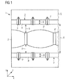
- FIG. 1 shows a section of a plan view of a section of the working surface of a tool according to the invention 1.
- the tool 1 in this case has a base G and two strips 2 and 2 ', which protrude in the z-direction from the main body G.
- the strips 2 and 2 ' run in the x direction.
- the strips 2 and 2 ' have notches 3 and 3', in this case, the surface of the strips 2 and 2 'in the z-direction notched down and recessed.
- the notches 3 and 3 ' thus arise the raised welding surfaces 4 and 4', which protrude in the z-direction from the working surface of the tool 1.
- the notches 3 and 3 ' are arranged equidistantly in the x direction, so that the resulting welding surfaces 4 and 4' equal length (and also the same width) are formed.
- the two strips 2 and 2 'of the tool 1 are mirror-symmetrical with respect to an x-axis. The minimum distance between these two strips d is the same over the entire x-dimensioning of the tool 1, so that the strips 2 and 2 'extend parallel to one another.
- the length of the welding surfaces 4 and 4 ' is between 1.0 and 10 mm, while the length of the notches in the x-direction 3 or 3' is between> 10 mm to 10 mm.
- the welding surfaces 4 and 4 'of the respective strips 2 and 2' in this case have a width B or B ', i. a dimensioning in the y direction.
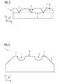
- the notches 3 and 3 'of the bar 2 and 2' may be triangular in shape (see also FIG. 2 ), so that the notches have corresponding flanks F, the indentations 3 "or the notches 5 or 5 'present between the strips can also be configured differently and, for example, have no edges, for example a round profile (see also FIG. 3 ).
- FIG. 2 shows a plan view of the xz-plane of the tool 1. Recognizable here are the regularly arranged triangular notches 3, each having flanks F. The flanks are arranged at an angle ⁇ to each other. In FIG. 2 is also the interaction of the welding surfaces 4 and the welding surfaces 4 "recognizable, the repetition rate of Welding surfaces 4 "in the x-direction is only half as high as the repetition rate of the welding surfaces 4, for example the first bar 2, so that only at the level of each second welding surface 4 of the bar 2 welding surfaces 4" of the bar 2 "are present.
- FIG. 3 shows a plan view of the tool according to the invention in the x-direction, ie on the yz plane.
- the FIG. 3 corresponds to a section in the yz plane through FIG. 1 at a location where both welding surfaces 4, 4 'and 4 "are formed FIG. 3 are the respective welding surfaces 4, 4 'and 4 "shown as raised in the z-direction recognizable, these welding surfaces are separated by notches 5 and 5', which in the case of the embodiment of FIG. 3 represent semicircular notches.
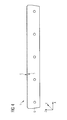
- FIG. 4 finally represents the overall perspective view of a welding tool 1 according to the invention, in this case, in particular, the enlarged dimensions of the body G is shown.
- the welding tool according to the invention has for the exemplary case of in FIG. 4 illustrated embodiment 80 notches 3 and a corresponding number of welding surfaces 4.
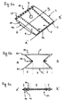
- FIGS. 5a to 5c show a vacuum cleaner filter bag 10 according to the invention, which is turned off as a flat bag.
- FIG. 5a shows a perspective view of the front side V of the vacuum cleaner filter bag 10 according to the invention in the form of a flat bag
- FIG. 5b the cut through the vacuum cleaner filter bag at the in FIG. 5a shown section line AB shows.
- FIG. 5c shows a section through the in FIG. 5a represented line A'-B ', ie by the circumferential weld S.
- the vacuum cleaner filter bag 10 in the form of a flat bag according to FIG. 5a has a front side V and a back side R.
- the front and rear sides V and R are each formed from a heat-sealable filter material, for example a monolayer or multilayer nonwoven material.
- the front side V has an inflow opening E, through which the outlet nozzle of a vacuum cleaner, not shown, can be connected to the vacuum cleaner filter bag 10.
- the front side V and the back side R are connected to each other circumferentially with a weld S.
- FIG. 5c is the inventive design of the weld in place of the section A'-B ', as in FIG. 5a shown shown.
- the weld seam S has alternating and equidistantly unwelded regions 30 and welded regions 40.
- the filter material of the front side V and the back side R are connected to one another.
- the thermally weldable filter material of both the front side V and the rear side R is melted and glued together.
- no fusion of the layers of the filter material takes place.
- the filter material of both the front V and the back R remains.
- the layers of the filter material V and R are in this case form-fitting one above the other and are deformed into beads.
- the embodiment of the weld according to the invention provides that the unwelded regions 30 along the weld, ie for the exemplary case of the representation in FIG. 5c along the section line A'-B ', have a dimension of> 1.0 mm to 5.0 mm.
- the welded regions 40 have a longitudinal dimension along the section line A'-B 'of 1.0 mm to 10.0 mm.
- the unwelded regions 30 and the welded regions 40 are arranged alternately and equidistantly, ie unwelded regions 40 and welded regions 30 alternate at the same repetition rate.
- FIG. 6a illustrates a vacuum cleaner filter bag 10 according to the invention in the form of a gusseted bag.
- This vacuum cleaner filter bag 10 has two longitudinal sides L and two lateral sides Q and also a front side V as a back side R.
- Front side V and rear side R are also formed from a thermally welded filter material, for example a monolayer or multilayer nonwoven material.
- On the front side V an inflow opening E is present.
- the filter material of both the front V and the back R is taken, so that the longitudinal side of two side edges K1 and K2 are present.
- the side edge K1 is present in the filter material of the front side V, while the side edge K2 of the filter material web is assigned to the rear side R.
- the front side V and the rear side R are connected to the front side, ie in the region of the transverse side Q by means of a weld S1, in the region of the impact front side V and rear side R are connected by means of a weld S2.
- FIG. 12 shows a section through the vacuum cleaner filter bag 10 according to the invention in the form of a flat bag along the section line AB, as in FIG FIG. 6a It can be seen how the filter material of the front side V as well as the back side R is wrapped and is connected there by means of a weld S2. By wrapping thereby arise the side edges K1 in the front V and K2 in the back R. By folding the front V and the back R arise in the vacuum cleaner filter bag 10 as a flat bag while two areas I and II, where - in the projection direction of the front V on the back R - for example, four layers of the filter material are arranged one above the other (area I) or two layers of the filter material are arranged one above the other (area II).
- FIG. 6c shows a section along the section line A'-B 'according to FIG. 6a , ie by a frontally arranged weld S1 of the vacuum cleaner filter bag 10 according to the invention in the form of a gusseted bag.
- this weld S1 has unwelded regions 30 or welded regions 40, on which the respective layers of the filter material of the front side and the back side R lying one above the other are connected to one another. All layers of the filter material are fused together within the weldable regions 40.
- area I where, as in FIG. 6b 4, four layers of the filter material come to lie one above the other, all of the four layers are fused together in the region of the welded regions 40.
- region II only two layers of the filter material are joined together within the welded regions 40, ie they are fused together.
- the unwelded regions 30 are thereby switched off within the regions I in such a way that the four layers of the filter material present there are present unconnected to one another, but are pressed against one another in a form-fitting manner. This creates the in FIG. 6c shown beads.
- Within of area II only two layers of the filter material are present, so that here an identical configuration of the weld as in FIG. 5c is shown.
- the weld S2, ie the weld seam located inside the vacuum cleaner filter bag at the connection point of the front side V and the back side R, can be carried out in an identical manner as in FIG FIG. 5c be designed.
- Table 1 shows experimental results that can be achieved in vacuum cleaner filter bags with inventively designed welds.
- Table 1 Examples Surface weight nonwoven (g / m 2 ) Number of welded layers Total weight per unit area (g / m 2 ) Width of the welding surface (mm) Length of welding surface (mm) Distance between the welding surfaces (mm) Corner) Tearing force (N) 1* 175 4 700 1.0 2.0 0.8 45 29 2 175 4 700 1.5 2.5 1.5 45 102 3 175 4 700 1.5 3.0 2.0 60 103 4 175 4 700 1.5 2.5 2.5 90 95
- Table 1 shows the results of the tensile force measurements using welded filter materials in accordance with DIN EN29073-3.
- the welded filter materials to be examined are clamped between the jaws of the tensile testing machine in such a way that the weld to be tested is arranged centrally between the jaws.
- the test specimens have 4 welded material layers, in each case two layers of the material are clamped in each jaw of the tensile testing machine.
- the welds of the examined samples have alternately arranged welded and unwelded areas.
- the distance between the welding surfaces is in each case only 0.8 mm, while in Examples 2-4 according to the invention the distance between the welding surfaces is chosen to be greater.
- Comparative Example 1 * clearly shows that a small distance between the welding surfaces gives poor results, especially with a high total basis weight of the welded material layers.
- the Examples 2, 3 and 4 according to the invention comparable to each other all show significantly higher tensile forces of the resulting weld seam, although the density of the weld points due to the greater distance of the welded regions to one another is lower than in Comparative Example 1 *.
- Example 2 shows that increasing the distance between the welding surfaces to, for example, 1.5 mm has excellent effects on the maximum tensile strength of the sample.
- an increase of the tensile strength by approx. 300% can be recognized.
- the increase in the distance between en welding surfaces thus surprisingly affects the result clearly positive.
- a further increase in the distance between the welding surfaces clearly shows that surprisingly, especially at high total areas weights, d. H.
- four welded layers a significant increase in tensile strength is observed.
Landscapes
- Engineering & Computer Science (AREA)
- Mechanical Engineering (AREA)
- Textile Engineering (AREA)
- Chemical & Material Sciences (AREA)
- Chemical Kinetics & Catalysis (AREA)
- Filters For Electric Vacuum Cleaners (AREA)
Priority Applications (6)
| Application Number | Priority Date | Filing Date | Title |
|---|---|---|---|
| EP14167974.6A EP2944247B1 (fr) | 2014-05-12 | 2014-05-12 | Sac filtrant d'aspirateur doté d'un cordon de soudure très résistant, son procédé de fabrication, outil et installation de soudage par ultrasons destinée à la fabrication d'un cordon de soudure très résistant |
| ES14167974.6T ES2600163T3 (es) | 2014-05-12 | 2014-05-12 | Bolsa de filtro para aspiradora con costura de soldadura altamente resistente, procedimiento para su producción, así como herramienta e instalación de soldadura por ultrasonidos para la producción de una costura de soldadura ultrarresistente |
| EP15719461.4A EP3142537B1 (fr) | 2014-05-12 | 2015-04-27 | Sac filtrant d'aspirateur doté d'un cordon de soudure très résistant, son procédé de fabrication, outillage et installation de soudage par ultrasons destinée à la fabrication d'un cordon de soudure extrêmement résistant |
| PCT/EP2015/058999 WO2015172995A1 (fr) | 2014-05-12 | 2015-04-27 | Sac pour filtre à poussière pour aspirateur, à cordon soudé à haute résistance, procédé pour sa production, et outil et installation de soudage par ultrasons pour la production d'un cordon soudé ultra résistant |
| ES15719461T ES2809901T3 (es) | 2014-05-12 | 2015-04-27 | Bolsa de filtro para aspiradora con costura de soldadura altamente resistente, procedimiento para su producción, así como herramienta e instalación de soldadura por ultrasonidos para la producción de una costura de soldadura ultrarresistente |
| US15/310,052 US10264936B2 (en) | 2014-05-12 | 2015-04-27 | Vacuum cleaner filter bag having a high-strength weld seam, method for producing said vacuum cleaner filter bag, and ultrasonic welding system for producing an ultra-strong weld seam |
Applications Claiming Priority (1)
| Application Number | Priority Date | Filing Date | Title |
|---|---|---|---|
| EP14167974.6A EP2944247B1 (fr) | 2014-05-12 | 2014-05-12 | Sac filtrant d'aspirateur doté d'un cordon de soudure très résistant, son procédé de fabrication, outil et installation de soudage par ultrasons destinée à la fabrication d'un cordon de soudure très résistant |
Publications (2)
| Publication Number | Publication Date |
|---|---|
| EP2944247A1 true EP2944247A1 (fr) | 2015-11-18 |
| EP2944247B1 EP2944247B1 (fr) | 2016-09-21 |
Family
ID=50685826
Family Applications (2)
| Application Number | Title | Priority Date | Filing Date |
|---|---|---|---|
| EP14167974.6A Active EP2944247B1 (fr) | 2014-05-12 | 2014-05-12 | Sac filtrant d'aspirateur doté d'un cordon de soudure très résistant, son procédé de fabrication, outil et installation de soudage par ultrasons destinée à la fabrication d'un cordon de soudure très résistant |
| EP15719461.4A Active EP3142537B1 (fr) | 2014-05-12 | 2015-04-27 | Sac filtrant d'aspirateur doté d'un cordon de soudure très résistant, son procédé de fabrication, outillage et installation de soudage par ultrasons destinée à la fabrication d'un cordon de soudure extrêmement résistant |
Family Applications After (1)
| Application Number | Title | Priority Date | Filing Date |
|---|---|---|---|
| EP15719461.4A Active EP3142537B1 (fr) | 2014-05-12 | 2015-04-27 | Sac filtrant d'aspirateur doté d'un cordon de soudure très résistant, son procédé de fabrication, outillage et installation de soudage par ultrasons destinée à la fabrication d'un cordon de soudure extrêmement résistant |
Country Status (4)
| Country | Link |
|---|---|
| US (1) | US10264936B2 (fr) |
| EP (2) | EP2944247B1 (fr) |
| ES (2) | ES2600163T3 (fr) |
| WO (1) | WO2015172995A1 (fr) |
Cited By (5)
| Publication number | Priority date | Publication date | Assignee | Title |
|---|---|---|---|---|
| EP3669734A1 (fr) | 2018-12-17 | 2020-06-24 | Eurofilters Holding N.V. | Sac filtrant d'aspirateur à résistance de cordon de soudure améliorée |
| WO2020164960A1 (fr) * | 2019-02-15 | 2020-08-20 | Wolf Pvg Gmbh & Co. Kg | Sac d'aspirateur et aspirateur |
| CN112566710A (zh) * | 2018-06-29 | 2021-03-26 | 纬湃科技有限责任公司 | 用于过滤吸取在叠置的两个过滤介质层之间的液体的装置 |
| CN114225571A (zh) * | 2021-12-30 | 2022-03-25 | 苏州科乐吉环保科技有限公司 | 一种新型环保过滤袋的生产方法和设备 |
| CN120055640A (zh) * | 2025-04-25 | 2025-05-30 | 广东新力新材料有限公司 | 一种焊接金属滤袋纵横缝的装置 |
Families Citing this family (1)
| Publication number | Priority date | Publication date | Assignee | Title |
|---|---|---|---|---|
| CN115253512B (zh) * | 2022-08-22 | 2024-01-02 | 安徽昊华环保科技有限公司 | 一种滤袋骨架的生产工艺 |
Citations (5)
| Publication number | Priority date | Publication date | Assignee | Title |
|---|---|---|---|---|
| WO1996032878A1 (fr) * | 1995-04-20 | 1996-10-24 | Minnesota Mining And Manufacturing Company | Sac filtrant pour aspirateur de grande efficacite et resistant aux chocs |
| WO2002043960A1 (fr) * | 2000-12-01 | 2002-06-06 | Stanhope Products Company | Modele de soudure ultrasonique ameliore destine aux emballages contenant un adsorbant |
| DE202004012754U1 (de) * | 2004-08-14 | 2004-10-14 | Telsonic Gmbh | Sammelbeutel |
| DE202005000918U1 (de) * | 2005-01-20 | 2005-03-31 | Branofilter Gmbh | Staubfilterbeutel |
| EP1795247A1 (fr) | 2005-12-12 | 2007-06-13 | Eurofilters N.V. | Sac à poussières d'aspirateur |
Family Cites Families (6)
| Publication number | Priority date | Publication date | Assignee | Title |
|---|---|---|---|---|
| DE10029797A1 (de) | 2000-06-16 | 2001-12-20 | Eul & Guenther Gmbh | Verfahren und Vorrichtung zum Herstellen mehrlagiger Produkte und zugehöriges Produkt |
| WO2002028508A1 (fr) | 2000-10-03 | 2002-04-11 | Valeo | Dispositif de filtration, notamment pour vehicule automobile, procede de fabrication tel dispositif de filtration et dispositif pour la mise en oeuvre du procede |
| DE20101466U1 (de) | 2001-01-27 | 2001-04-19 | Wolf GmbH, 32602 Vlotho | In einen Staubsauger einsetzbare Filtereinrichtung |
| DE202005016309U1 (de) * | 2005-10-18 | 2005-12-15 | Wolf Gmbh | Staubsaugerbeutel |
| GB0819209D0 (en) * | 2008-10-20 | 2008-11-26 | Numatic Int Ltd | Vacuum cleaning filter arrangement |
| DE202011000339U1 (de) | 2011-02-15 | 2011-04-14 | Wolf Pvg Gmbh & Co. Kg | Staubsaugerbeutel |
-
2014
- 2014-05-12 EP EP14167974.6A patent/EP2944247B1/fr active Active
- 2014-05-12 ES ES14167974.6T patent/ES2600163T3/es active Active
-
2015
- 2015-04-27 ES ES15719461T patent/ES2809901T3/es active Active
- 2015-04-27 WO PCT/EP2015/058999 patent/WO2015172995A1/fr not_active Ceased
- 2015-04-27 US US15/310,052 patent/US10264936B2/en active Active
- 2015-04-27 EP EP15719461.4A patent/EP3142537B1/fr active Active
Patent Citations (5)
| Publication number | Priority date | Publication date | Assignee | Title |
|---|---|---|---|---|
| WO1996032878A1 (fr) * | 1995-04-20 | 1996-10-24 | Minnesota Mining And Manufacturing Company | Sac filtrant pour aspirateur de grande efficacite et resistant aux chocs |
| WO2002043960A1 (fr) * | 2000-12-01 | 2002-06-06 | Stanhope Products Company | Modele de soudure ultrasonique ameliore destine aux emballages contenant un adsorbant |
| DE202004012754U1 (de) * | 2004-08-14 | 2004-10-14 | Telsonic Gmbh | Sammelbeutel |
| DE202005000918U1 (de) * | 2005-01-20 | 2005-03-31 | Branofilter Gmbh | Staubfilterbeutel |
| EP1795247A1 (fr) | 2005-12-12 | 2007-06-13 | Eurofilters N.V. | Sac à poussières d'aspirateur |
Cited By (10)
| Publication number | Priority date | Publication date | Assignee | Title |
|---|---|---|---|---|
| CN112566710A (zh) * | 2018-06-29 | 2021-03-26 | 纬湃科技有限责任公司 | 用于过滤吸取在叠置的两个过滤介质层之间的液体的装置 |
| EP3669734A1 (fr) | 2018-12-17 | 2020-06-24 | Eurofilters Holding N.V. | Sac filtrant d'aspirateur à résistance de cordon de soudure améliorée |
| EP3669735A1 (fr) | 2018-12-17 | 2020-06-24 | Eurofilters Holding N.V. | Sac filtrant d'aspirateur à résistance de cordon de soudure améliorée |
| WO2020127065A1 (fr) | 2018-12-17 | 2020-06-25 | Eurofilters Holding N.V. | Sac de filtre d'aspirateur ayant une résistance de cordon de soudure améliorée |
| CN113226140A (zh) * | 2018-12-17 | 2021-08-06 | 欧罗菲利特斯控股公司 | 具有改善的熔接缝强度的真空清洁器过滤袋 |
| CN113226140B (zh) * | 2018-12-17 | 2022-08-12 | 欧罗菲利特斯控股公司 | 具有改善的熔接缝强度的真空清洁器过滤袋 |
| WO2020164960A1 (fr) * | 2019-02-15 | 2020-08-20 | Wolf Pvg Gmbh & Co. Kg | Sac d'aspirateur et aspirateur |
| CN114225571A (zh) * | 2021-12-30 | 2022-03-25 | 苏州科乐吉环保科技有限公司 | 一种新型环保过滤袋的生产方法和设备 |
| CN114225571B (zh) * | 2021-12-30 | 2023-06-30 | 昆山市华滤环保科技有限公司 | 一种新型环保过滤袋的生产方法和设备 |
| CN120055640A (zh) * | 2025-04-25 | 2025-05-30 | 广东新力新材料有限公司 | 一种焊接金属滤袋纵横缝的装置 |
Also Published As
| Publication number | Publication date |
|---|---|
| ES2600163T3 (es) | 2017-02-07 |
| ES2809901T3 (es) | 2021-03-08 |
| US10264936B2 (en) | 2019-04-23 |
| EP3142537B1 (fr) | 2020-05-13 |
| EP2944247B1 (fr) | 2016-09-21 |
| US20170265699A1 (en) | 2017-09-21 |
| WO2015172995A1 (fr) | 2015-11-19 |
| EP3142537A1 (fr) | 2017-03-22 |
Similar Documents
| Publication | Publication Date | Title |
|---|---|---|
| EP3142537B1 (fr) | Sac filtrant d'aspirateur doté d'un cordon de soudure très résistant, son procédé de fabrication, outillage et installation de soudage par ultrasons destinée à la fabrication d'un cordon de soudure extrêmement résistant | |
| DE3688074T2 (de) | Ultraschallschweissvorrichtung mit kontaktflaechen. | |
| DE60116189T2 (de) | Vorrichtung zum Schweissen einer Spleissverbindung | |
| DE202013012778U1 (de) | Vorrichtung zum Verschweißen von profilierten Elementen aus Kunststoffmaterial, insbesondere PVC | |
| EP1258557A2 (fr) | Procédé pour lier des pièces de tissu | |
| EP2988919B1 (fr) | Dispositif de soudage par ultrasons équipé de plusieurs sonotrodes | |
| EP3386363B1 (fr) | Procede de liaison interposee d'une plaque de support et d'une paroi d'un sac d'aspirateur et sac d'aspirateur | |
| DE102012202016B4 (de) | Verfahren und Vorrichtung zur Konfektionierung von dünnen Kunststofffolien | |
| EP2504150B1 (fr) | Procédé pour fermer un corps de sac | |
| DE69310019T2 (de) | Heisssiegelvorrichtung | |
| DE102010043089A1 (de) | Siegelbacke zur Siegelung eines Packstoffs mittels Ultraschall | |
| EP2384255A2 (fr) | Procédé de réalisation de joints soudés à recouvrement et joint soudé à recouvrement | |
| DE102009043144A1 (de) | Vorrichtung zum Ultraschallschweißen eines Werkstücks | |
| EP1535723A2 (fr) | Dispositif pour le soudage de feuilles multicouches | |
| WO2019038334A1 (fr) | Procédé de soudage pour un composite multicouche comprenant une couche barrière | |
| DE102016117908A1 (de) | Werkzeug für einen Ultraschall-Rohrverschliesser zum Verschliessen eines Endbereiches eines Rohres mit einem doppelten Verschluss | |
| DE102010021703A1 (de) | Verpackungseinheit | |
| EP1928288A1 (fr) | Sac pour aspirateur et procede de production de ce sac | |
| EP3357392B1 (fr) | Plaque support pour un sac filtrant d'aspirateur comprenant un dispositif de fermeture | |
| DE102004032833B4 (de) | Mehrlagiges Formteil und Verfahren zu seiner Herstellung | |
| DE102017117078A1 (de) | Sonotrode sowie Verfahren zur Beeinflussung des Schwingungsverhaltens einer Sonotrode | |
| EP3216905A1 (fr) | Matiere non tissee pouvant etre soudee, procede de fabrication d'une matiere non tissee et emballage | |
| WO2023061803A1 (fr) | Outil pour dispositif de soudage par ultrasons et procédé associé | |
| DE102020205247A1 (de) | Zickzack-gefaltetes vliesmaterial | |
| DE102014223907A1 (de) | Sonotrode, Schweißvorrichtung mit Sonotrode sowie dazugehöriges Schweißverfahren |
Legal Events
| Date | Code | Title | Description |
|---|---|---|---|
| PUAI | Public reference made under article 153(3) epc to a published international application that has entered the european phase |
Free format text: ORIGINAL CODE: 0009012 |
|
| 17P | Request for examination filed |
Effective date: 20150210 |
|
| AK | Designated contracting states |
Kind code of ref document: A1 Designated state(s): AL AT BE BG CH CY CZ DE DK EE ES FI FR GB GR HR HU IE IS IT LI LT LU LV MC MK MT NL NO PL PT RO RS SE SI SK SM TR |
|
| AX | Request for extension of the european patent |
Extension state: BA ME |
|
| 17Q | First examination report despatched |
Effective date: 20151027 |
|
| GRAP | Despatch of communication of intention to grant a patent |
Free format text: ORIGINAL CODE: EPIDOSNIGR1 |
|
| INTG | Intention to grant announced |
Effective date: 20160419 |
|
| GRAS | Grant fee paid |
Free format text: ORIGINAL CODE: EPIDOSNIGR3 |
|
| GRAA | (expected) grant |
Free format text: ORIGINAL CODE: 0009210 |
|
| AK | Designated contracting states |
Kind code of ref document: B1 Designated state(s): AL AT BE BG CH CY CZ DE DK EE ES FI FR GB GR HR HU IE IS IT LI LT LU LV MC MK MT NL NO PL PT RO RS SE SI SK SM TR |
|
| REG | Reference to a national code |
Ref country code: GB Ref legal event code: FG4D Free format text: NOT ENGLISH |
|
| REG | Reference to a national code |
Ref country code: CH Ref legal event code: EP |
|
| REG | Reference to a national code |
Ref country code: AT Ref legal event code: REF Ref document number: 830359 Country of ref document: AT Kind code of ref document: T Effective date: 20161015 |
|
| REG | Reference to a national code |
Ref country code: IE Ref legal event code: FG4D Free format text: LANGUAGE OF EP DOCUMENT: GERMAN |
|
| REG | Reference to a national code |
Ref country code: NL Ref legal event code: FP |
|
| REG | Reference to a national code |
Ref country code: DE Ref legal event code: R096 Ref document number: 502014001499 Country of ref document: DE |
|
| REG | Reference to a national code |
Ref country code: SE Ref legal event code: TRGR |
|
| REG | Reference to a national code |
Ref country code: LT Ref legal event code: MG4D |
|
| PG25 | Lapsed in a contracting state [announced via postgrant information from national office to epo] |
Ref country code: LT Free format text: LAPSE BECAUSE OF FAILURE TO SUBMIT A TRANSLATION OF THE DESCRIPTION OR TO PAY THE FEE WITHIN THE PRESCRIBED TIME-LIMIT Effective date: 20160921 Ref country code: NO Free format text: LAPSE BECAUSE OF FAILURE TO SUBMIT A TRANSLATION OF THE DESCRIPTION OR TO PAY THE FEE WITHIN THE PRESCRIBED TIME-LIMIT Effective date: 20161221 Ref country code: RS Free format text: LAPSE BECAUSE OF FAILURE TO SUBMIT A TRANSLATION OF THE DESCRIPTION OR TO PAY THE FEE WITHIN THE PRESCRIBED TIME-LIMIT Effective date: 20160921 Ref country code: FI Free format text: LAPSE BECAUSE OF FAILURE TO SUBMIT A TRANSLATION OF THE DESCRIPTION OR TO PAY THE FEE WITHIN THE PRESCRIBED TIME-LIMIT Effective date: 20160921 |
|
| REG | Reference to a national code |
Ref country code: ES Ref legal event code: FG2A Ref document number: 2600163 Country of ref document: ES Kind code of ref document: T3 Effective date: 20170207 |
|
| PG25 | Lapsed in a contracting state [announced via postgrant information from national office to epo] |
Ref country code: LV Free format text: LAPSE BECAUSE OF FAILURE TO SUBMIT A TRANSLATION OF THE DESCRIPTION OR TO PAY THE FEE WITHIN THE PRESCRIBED TIME-LIMIT Effective date: 20160921 Ref country code: GR Free format text: LAPSE BECAUSE OF FAILURE TO SUBMIT A TRANSLATION OF THE DESCRIPTION OR TO PAY THE FEE WITHIN THE PRESCRIBED TIME-LIMIT Effective date: 20161222 |
|
| PG25 | Lapsed in a contracting state [announced via postgrant information from national office to epo] |
Ref country code: RO Free format text: LAPSE BECAUSE OF FAILURE TO SUBMIT A TRANSLATION OF THE DESCRIPTION OR TO PAY THE FEE WITHIN THE PRESCRIBED TIME-LIMIT Effective date: 20160921 Ref country code: EE Free format text: LAPSE BECAUSE OF FAILURE TO SUBMIT A TRANSLATION OF THE DESCRIPTION OR TO PAY THE FEE WITHIN THE PRESCRIBED TIME-LIMIT Effective date: 20160921 |
|
| REG | Reference to a national code |
Ref country code: FR Ref legal event code: PLFP Year of fee payment: 4 |
|
| PG25 | Lapsed in a contracting state [announced via postgrant information from national office to epo] |
Ref country code: CZ Free format text: LAPSE BECAUSE OF FAILURE TO SUBMIT A TRANSLATION OF THE DESCRIPTION OR TO PAY THE FEE WITHIN THE PRESCRIBED TIME-LIMIT Effective date: 20160921 Ref country code: PL Free format text: LAPSE BECAUSE OF FAILURE TO SUBMIT A TRANSLATION OF THE DESCRIPTION OR TO PAY THE FEE WITHIN THE PRESCRIBED TIME-LIMIT Effective date: 20160921 Ref country code: SK Free format text: LAPSE BECAUSE OF FAILURE TO SUBMIT A TRANSLATION OF THE DESCRIPTION OR TO PAY THE FEE WITHIN THE PRESCRIBED TIME-LIMIT Effective date: 20160921 Ref country code: BG Free format text: LAPSE BECAUSE OF FAILURE TO SUBMIT A TRANSLATION OF THE DESCRIPTION OR TO PAY THE FEE WITHIN THE PRESCRIBED TIME-LIMIT Effective date: 20161221 Ref country code: SM Free format text: LAPSE BECAUSE OF FAILURE TO SUBMIT A TRANSLATION OF THE DESCRIPTION OR TO PAY THE FEE WITHIN THE PRESCRIBED TIME-LIMIT Effective date: 20160921 Ref country code: PT Free format text: LAPSE BECAUSE OF FAILURE TO SUBMIT A TRANSLATION OF THE DESCRIPTION OR TO PAY THE FEE WITHIN THE PRESCRIBED TIME-LIMIT Effective date: 20170123 Ref country code: IS Free format text: LAPSE BECAUSE OF FAILURE TO SUBMIT A TRANSLATION OF THE DESCRIPTION OR TO PAY THE FEE WITHIN THE PRESCRIBED TIME-LIMIT Effective date: 20170121 |
|
| REG | Reference to a national code |
Ref country code: DE Ref legal event code: R026 Ref document number: 502014001499 Country of ref document: DE |
|
| PLBI | Opposition filed |
Free format text: ORIGINAL CODE: 0009260 |
|
| PLAX | Notice of opposition and request to file observation + time limit sent |
Free format text: ORIGINAL CODE: EPIDOSNOBS2 |
|
| 26 | Opposition filed |
Opponent name: WOLF PVG GMBH & CO. KG Effective date: 20170620 |
|
| PG25 | Lapsed in a contracting state [announced via postgrant information from national office to epo] |
Ref country code: DK Free format text: LAPSE BECAUSE OF FAILURE TO SUBMIT A TRANSLATION OF THE DESCRIPTION OR TO PAY THE FEE WITHIN THE PRESCRIBED TIME-LIMIT Effective date: 20160921 |
|
| PLAF | Information modified related to communication of a notice of opposition and request to file observations + time limit |
Free format text: ORIGINAL CODE: EPIDOSCOBS2 |
|
| PG25 | Lapsed in a contracting state [announced via postgrant information from national office to epo] |
Ref country code: SI Free format text: LAPSE BECAUSE OF FAILURE TO SUBMIT A TRANSLATION OF THE DESCRIPTION OR TO PAY THE FEE WITHIN THE PRESCRIBED TIME-LIMIT Effective date: 20160921 |
|
| PLBB | Reply of patent proprietor to notice(s) of opposition received |
Free format text: ORIGINAL CODE: EPIDOSNOBS3 |
|
| PG25 | Lapsed in a contracting state [announced via postgrant information from national office to epo] |
Ref country code: MC Free format text: LAPSE BECAUSE OF FAILURE TO SUBMIT A TRANSLATION OF THE DESCRIPTION OR TO PAY THE FEE WITHIN THE PRESCRIBED TIME-LIMIT Effective date: 20160921 |
|
| REG | Reference to a national code |
Ref country code: IE Ref legal event code: MM4A |
|
| PG25 | Lapsed in a contracting state [announced via postgrant information from national office to epo] |
Ref country code: IE Free format text: LAPSE BECAUSE OF NON-PAYMENT OF DUE FEES Effective date: 20170512 |
|
| REG | Reference to a national code |
Ref country code: FR Ref legal event code: PLFP Year of fee payment: 5 |
|
| PG25 | Lapsed in a contracting state [announced via postgrant information from national office to epo] |
Ref country code: MT Free format text: LAPSE BECAUSE OF FAILURE TO SUBMIT A TRANSLATION OF THE DESCRIPTION OR TO PAY THE FEE WITHIN THE PRESCRIBED TIME-LIMIT Effective date: 20160921 |
|
| PG25 | Lapsed in a contracting state [announced via postgrant information from national office to epo] |
Ref country code: AL Free format text: LAPSE BECAUSE OF FAILURE TO SUBMIT A TRANSLATION OF THE DESCRIPTION OR TO PAY THE FEE WITHIN THE PRESCRIBED TIME-LIMIT Effective date: 20160921 |
|
| PG25 | Lapsed in a contracting state [announced via postgrant information from national office to epo] |
Ref country code: HU Free format text: LAPSE BECAUSE OF FAILURE TO SUBMIT A TRANSLATION OF THE DESCRIPTION OR TO PAY THE FEE WITHIN THE PRESCRIBED TIME-LIMIT; INVALID AB INITIO Effective date: 20140512 |
|
| PG25 | Lapsed in a contracting state [announced via postgrant information from national office to epo] |
Ref country code: CY Free format text: LAPSE BECAUSE OF FAILURE TO SUBMIT A TRANSLATION OF THE DESCRIPTION OR TO PAY THE FEE WITHIN THE PRESCRIBED TIME-LIMIT Effective date: 20160921 |
|
| PG25 | Lapsed in a contracting state [announced via postgrant information from national office to epo] |
Ref country code: MK Free format text: LAPSE BECAUSE OF FAILURE TO SUBMIT A TRANSLATION OF THE DESCRIPTION OR TO PAY THE FEE WITHIN THE PRESCRIBED TIME-LIMIT Effective date: 20160921 |
|
| PG25 | Lapsed in a contracting state [announced via postgrant information from national office to epo] |
Ref country code: HR Free format text: LAPSE BECAUSE OF FAILURE TO SUBMIT A TRANSLATION OF THE DESCRIPTION OR TO PAY THE FEE WITHIN THE PRESCRIBED TIME-LIMIT Effective date: 20160921 |
|
| REG | Reference to a national code |
Ref country code: DE Ref legal event code: R082 Ref document number: 502014001499 Country of ref document: DE Representative=s name: GRUENECKER PATENT- UND RECHTSANWAELTE PARTG MB, DE |
|
| PGFP | Annual fee paid to national office [announced via postgrant information from national office to epo] |
Ref country code: LU Payment date: 20220531 Year of fee payment: 9 |
|
| PGFP | Annual fee paid to national office [announced via postgrant information from national office to epo] |
Ref country code: TR Payment date: 20220506 Year of fee payment: 9 Ref country code: CH Payment date: 20220519 Year of fee payment: 9 Ref country code: AT Payment date: 20220523 Year of fee payment: 9 |
|
| PGFP | Annual fee paid to national office [announced via postgrant information from national office to epo] |
Ref country code: ES Payment date: 20220725 Year of fee payment: 9 |
|
| PLCK | Communication despatched that opposition was rejected |
Free format text: ORIGINAL CODE: EPIDOSNREJ1 |
|
| STAA | Information on the status of an ep patent application or granted ep patent |
Free format text: STATUS: THE PATENT HAS BEEN GRANTED |
|
| APAH | Appeal reference modified |
Free format text: ORIGINAL CODE: EPIDOSCREFNO |
|
| APBM | Appeal reference recorded |
Free format text: ORIGINAL CODE: EPIDOSNREFNO |
|
| APBP | Date of receipt of notice of appeal recorded |
Free format text: ORIGINAL CODE: EPIDOSNNOA2O |
|
| APBQ | Date of receipt of statement of grounds of appeal recorded |
Free format text: ORIGINAL CODE: EPIDOSNNOA3O |
|
| REG | Reference to a national code |
Ref country code: CH Ref legal event code: PL |
|
| REG | Reference to a national code |
Ref country code: AT Ref legal event code: MM01 Ref document number: 830359 Country of ref document: AT Kind code of ref document: T Effective date: 20230512 |
|
| PG25 | Lapsed in a contracting state [announced via postgrant information from national office to epo] |
Ref country code: LU Free format text: LAPSE BECAUSE OF NON-PAYMENT OF DUE FEES Effective date: 20230512 Ref country code: LI Free format text: LAPSE BECAUSE OF NON-PAYMENT OF DUE FEES Effective date: 20230531 Ref country code: CH Free format text: LAPSE BECAUSE OF NON-PAYMENT OF DUE FEES Effective date: 20230531 Ref country code: AT Free format text: LAPSE BECAUSE OF NON-PAYMENT OF DUE FEES Effective date: 20230512 |
|
| REG | Reference to a national code |
Ref country code: ES Ref legal event code: FD2A Effective date: 20240628 |
|
| PG25 | Lapsed in a contracting state [announced via postgrant information from national office to epo] |
Ref country code: ES Free format text: LAPSE BECAUSE OF NON-PAYMENT OF DUE FEES Effective date: 20230513 |
|
| PG25 | Lapsed in a contracting state [announced via postgrant information from national office to epo] |
Ref country code: ES Free format text: LAPSE BECAUSE OF NON-PAYMENT OF DUE FEES Effective date: 20230513 |
|
| APBU | Appeal procedure closed |
Free format text: ORIGINAL CODE: EPIDOSNNOA9O |
|
| PGFP | Annual fee paid to national office [announced via postgrant information from national office to epo] |
Ref country code: NL Payment date: 20250523 Year of fee payment: 12 |
|
| PGFP | Annual fee paid to national office [announced via postgrant information from national office to epo] |
Ref country code: DE Payment date: 20250528 Year of fee payment: 12 |
|
| PGFP | Annual fee paid to national office [announced via postgrant information from national office to epo] |
Ref country code: GB Payment date: 20250524 Year of fee payment: 12 |
|
| PGFP | Annual fee paid to national office [announced via postgrant information from national office to epo] |
Ref country code: BE Payment date: 20250520 Year of fee payment: 12 Ref country code: IT Payment date: 20250529 Year of fee payment: 12 |
|
| PGFP | Annual fee paid to national office [announced via postgrant information from national office to epo] |
Ref country code: FR Payment date: 20250520 Year of fee payment: 12 |
|
| PGFP | Annual fee paid to national office [announced via postgrant information from national office to epo] |
Ref country code: SE Payment date: 20250524 Year of fee payment: 12 |
|
| REG | Reference to a national code |
Ref country code: DE Ref legal event code: R008 Ref document number: 502014001499 Country of ref document: DE Ref country code: DE Ref legal event code: R039 Ref document number: 502014001499 Country of ref document: DE |