EP2944347A1 - Medizinische Ballonanordnung und Verfahren zur Herstellung eines medizinischen Ballons - Google Patents
Medizinische Ballonanordnung und Verfahren zur Herstellung eines medizinischen Ballons Download PDFInfo
- Publication number
- EP2944347A1 EP2944347A1 EP15275029.5A EP15275029A EP2944347A1 EP 2944347 A1 EP2944347 A1 EP 2944347A1 EP 15275029 A EP15275029 A EP 15275029A EP 2944347 A1 EP2944347 A1 EP 2944347A1
- Authority
- EP
- European Patent Office
- Prior art keywords
- balloon
- layer
- overlying
- medical balloon
- underlying layer
- Prior art date
- Legal status (The legal status is an assumption and is not a legal conclusion. Google has not performed a legal analysis and makes no representation as to the accuracy of the status listed.)
- Granted
Links
Images


Classifications
-
- A—HUMAN NECESSITIES
- A61—MEDICAL OR VETERINARY SCIENCE; HYGIENE
- A61M—DEVICES FOR INTRODUCING MEDIA INTO, OR ONTO, THE BODY; DEVICES FOR TRANSDUCING BODY MEDIA OR FOR TAKING MEDIA FROM THE BODY; DEVICES FOR PRODUCING OR ENDING SLEEP OR STUPOR
- A61M25/00—Catheters; Hollow probes
- A61M25/10—Balloon catheters
-
- A—HUMAN NECESSITIES
- A61—MEDICAL OR VETERINARY SCIENCE; HYGIENE
- A61M—DEVICES FOR INTRODUCING MEDIA INTO, OR ONTO, THE BODY; DEVICES FOR TRANSDUCING BODY MEDIA OR FOR TAKING MEDIA FROM THE BODY; DEVICES FOR PRODUCING OR ENDING SLEEP OR STUPOR
- A61M25/00—Catheters; Hollow probes
- A61M25/10—Balloon catheters
- A61M25/1027—Making of balloon catheters
- A61M25/1029—Production methods of the balloon members, e.g. blow-moulding, extruding, deposition or by wrapping a plurality of layers of balloon material around a mandril
-
- A—HUMAN NECESSITIES
- A61—MEDICAL OR VETERINARY SCIENCE; HYGIENE
- A61M—DEVICES FOR INTRODUCING MEDIA INTO, OR ONTO, THE BODY; DEVICES FOR TRANSDUCING BODY MEDIA OR FOR TAKING MEDIA FROM THE BODY; DEVICES FOR PRODUCING OR ENDING SLEEP OR STUPOR
- A61M25/00—Catheters; Hollow probes
- A61M25/10—Balloon catheters
- A61M25/1027—Making of balloon catheters
-
- A—HUMAN NECESSITIES
- A61—MEDICAL OR VETERINARY SCIENCE; HYGIENE
- A61L—METHODS OR APPARATUS FOR STERILISING MATERIALS OR OBJECTS IN GENERAL; DISINFECTION, STERILISATION OR DEODORISATION OF AIR; CHEMICAL ASPECTS OF BANDAGES, DRESSINGS, ABSORBENT PADS OR SURGICAL ARTICLES; MATERIALS FOR BANDAGES, DRESSINGS, ABSORBENT PADS OR SURGICAL ARTICLES
- A61L29/00—Materials for catheters, medical tubing, cannulae, or endoscopes or for coating catheters
- A61L29/04—Macromolecular materials
- A61L29/041—Macromolecular materials obtained by reactions only involving carbon-to-carbon unsaturated bonds
-
- A—HUMAN NECESSITIES
- A61—MEDICAL OR VETERINARY SCIENCE; HYGIENE
- A61L—METHODS OR APPARATUS FOR STERILISING MATERIALS OR OBJECTS IN GENERAL; DISINFECTION, STERILISATION OR DEODORISATION OF AIR; CHEMICAL ASPECTS OF BANDAGES, DRESSINGS, ABSORBENT PADS OR SURGICAL ARTICLES; MATERIALS FOR BANDAGES, DRESSINGS, ABSORBENT PADS OR SURGICAL ARTICLES
- A61L29/00—Materials for catheters, medical tubing, cannulae, or endoscopes or for coating catheters
- A61L29/04—Macromolecular materials
- A61L29/06—Macromolecular materials obtained otherwise than by reactions only involving carbon-to-carbon unsaturated bonds
-
- A—HUMAN NECESSITIES
- A61—MEDICAL OR VETERINARY SCIENCE; HYGIENE
- A61M—DEVICES FOR INTRODUCING MEDIA INTO, OR ONTO, THE BODY; DEVICES FOR TRANSDUCING BODY MEDIA OR FOR TAKING MEDIA FROM THE BODY; DEVICES FOR PRODUCING OR ENDING SLEEP OR STUPOR
- A61M25/00—Catheters; Hollow probes
- A61M25/10—Balloon catheters
- A61M25/1027—Making of balloon catheters
- A61M25/1029—Production methods of the balloon members, e.g. blow-moulding, extruding, deposition or by wrapping a plurality of layers of balloon material around a mandril
- A61M2025/1031—Surface processing of balloon members, e.g. coating or deposition; Mounting additional parts onto the balloon member's surface
-
- A—HUMAN NECESSITIES
- A61—MEDICAL OR VETERINARY SCIENCE; HYGIENE
- A61M—DEVICES FOR INTRODUCING MEDIA INTO, OR ONTO, THE BODY; DEVICES FOR TRANSDUCING BODY MEDIA OR FOR TAKING MEDIA FROM THE BODY; DEVICES FOR PRODUCING OR ENDING SLEEP OR STUPOR
- A61M25/00—Catheters; Hollow probes
- A61M25/10—Balloon catheters
- A61M2025/1043—Balloon catheters with special features or adapted for special applications
- A61M2025/1075—Balloon catheters with special features or adapted for special applications having a balloon composed of several layers, e.g. by coating or embedding
-
- A—HUMAN NECESSITIES
- A61—MEDICAL OR VETERINARY SCIENCE; HYGIENE
- A61M—DEVICES FOR INTRODUCING MEDIA INTO, OR ONTO, THE BODY; DEVICES FOR TRANSDUCING BODY MEDIA OR FOR TAKING MEDIA FROM THE BODY; DEVICES FOR PRODUCING OR ENDING SLEEP OR STUPOR
- A61M25/00—Catheters; Hollow probes
- A61M25/10—Balloon catheters
- A61M2025/1043—Balloon catheters with special features or adapted for special applications
- A61M2025/1086—Balloon catheters with special features or adapted for special applications having a special balloon surface topography, e.g. pores, protuberances, spikes or grooves
-
- A—HUMAN NECESSITIES
- A61—MEDICAL OR VETERINARY SCIENCE; HYGIENE
- A61M—DEVICES FOR INTRODUCING MEDIA INTO, OR ONTO, THE BODY; DEVICES FOR TRANSDUCING BODY MEDIA OR FOR TAKING MEDIA FROM THE BODY; DEVICES FOR PRODUCING OR ENDING SLEEP OR STUPOR
- A61M25/00—Catheters; Hollow probes
- A61M25/10—Balloon catheters
- A61M2025/1043—Balloon catheters with special features or adapted for special applications
- A61M2025/1088—Balloon catheters with special features or adapted for special applications having special surface characteristics depending on material properties or added substances, e.g. for reducing friction
-
- A—HUMAN NECESSITIES
- A61—MEDICAL OR VETERINARY SCIENCE; HYGIENE
- A61M—DEVICES FOR INTRODUCING MEDIA INTO, OR ONTO, THE BODY; DEVICES FOR TRANSDUCING BODY MEDIA OR FOR TAKING MEDIA FROM THE BODY; DEVICES FOR PRODUCING OR ENDING SLEEP OR STUPOR
- A61M25/00—Catheters; Hollow probes
- A61M25/10—Balloon catheters
- A61M2025/1043—Balloon catheters with special features or adapted for special applications
- A61M2025/109—Balloon catheters with special features or adapted for special applications having balloons for removing solid matters, e.g. by grasping or scraping plaque, thrombus or other matters that obstruct the flow
Definitions
- the present invention relates to a medical balloon, for example but not limited to a balloon used for angioplasty procedures, for valve repair procedures, for occluding vessels and for deploying an implantable medical device.
- the invention also relates to a method of making such a balloon.
- a balloon with a smooth outer surface can be disadvantageous, including for instance slippage of the balloon in a vessel or across a valve opening, slippage of a medical device carried on the balloon and so on.
- attempts have been made to form balloons with roughened or textured outer surfaces. This may be achieved, for instance, by blowing a raw tubing in a textured or shaped mold such that the raw tubing is inflated against the mold surface, acquiring the shape of the mold surface.
- a balloon which is textured or shaped in this manner, that is by shaping the wall thereof, will retain a thin balloon wall and thus maintain the same foldability and wrappability as a conventional balloon.
- balloons can be inflated into the molded shape, in practice they tend to lose any surface roughness or texturing as a result of stretching of the balloon wall under inflation pressure. This smoothing and flattening effect becomes more pronounced the greater the pressure to which the balloon is inflated.
- the balloon must be inflated to a high pressure, for instance to break through vessel plaque, to deploy an implantable medical device and so on, in which case the outer balloon surface can become virtually smooth.
- the present invention seeks to provide an improved medical balloon and method of making such a balloon.
- a medical balloon having a balloon wall encapsulating a balloon chamber, the balloon being expandable by inflating the chamber with inflation fluid; wherein the balloon wall is formed of at least two layers overlying one another, an outer layer formed of a material having a first softening or melting temperature and an underlying layer formed of a material having a second softening or melting temperature, wherein the second temperature is lower than the first temperature.
- an underlying, or inner, layer to the balloon which has a softening or melting temperature lower than that of an overlying or outer layer of the balloon enables the underlying layer to fill any recesses or cavities in the outer layer, formed for instance for texturing, roughening or shaping of the balloon, in a manner such that the underlying layer will support the outer layer during subsequent inflation of the balloon and prevent stretching of the outer layer, as can occur in prior art devices.
- the underlying layer extends across the entire expanse of the overlying layer.
- the overlying layer may be the outermost layer of the balloon, while the underlying layer may be the innermost layer of the balloon. It is not excluded, however, that the balloon could have additional layers thereto, even between the underlying and overlying layers.
- the balloon could be one of: roughened, textured and shaped.
- the underlying layer is made of a reflow material, for example a polyolefin such as AdmerTM; while the overlying layer may be made of a polyamide such as Nylon, a polyether block amide such as PebaxTM or polyethylene terephthalate (PET).
- a reflow material for example a polyolefin such as AdmerTM
- AdmerTM polyolefin
- the overlying layer may be made of a polyamide such as Nylon, a polyether block amide such as PebaxTM or polyethylene terephthalate (PET).
- a method of making a medical balloon including the steps of: disposing a raw tubing of balloon material in a mold, the mold having an inner mold surface having a shape consistent with that of the balloon to be formed, the raw tubing having a wall formed of at least two layers overlying one another, an outer layer formed of a material having a first softening or melting temperature and an underlying layer formed of a material having a second softening or melting temperature, wherein the second temperature is lower than the first temperature; inflating the raw tubing simultaneously with subjecting the raw tubing to heat, said inflation causing the raw tubing to expand to the inner mold surface and to form the medical balloon; wherein the heat causes melting or softening of the underlying layer, whereupon the material of the underlying layer flows into any recesses or cavities in the overlying layer.
- the underlying layer is made to soften or melt so as to flow relative to the overlying layer, so as to be able to flow into any recesses, cavities or interstices in the inner surface of the overlying layer.
- the underlying layer has a smooth inner surface, typically having the minimum surface area possible, which assists in supporting the overlying layer during use of the balloon.
- FIG. 1 shows in schematic form a cross-sectional view of an example of medical balloon 10 having a body portion 12, of generally cylindrical form in this example, and first and second end cones 14 and 16 either side of the body portion 12.
- a balloon neck 18, 20 At the end of each cone portion 14, 16 there is a balloon neck 18, 20, the necks in practice fixed in fluid tight manner to a balloon catheter (not shown in the drawings).
- the balloon has an internal chamber which can be filled via a supply lumen in the balloon catheter with inflation fluid, typically saline solution or contrast media. When deflated, that is emptied of inflation fluid, the balloon 10 can be folded and wrapped around the balloon catheter, in a manner known in the art.
- the outer surface of the body portion 12 is roughened or textured in order to give the balloon 10 a non-smooth outer surface.
- Such texturing or roughening may be provided in order to seek to reduce the risk of slippage of the balloon 10 when deployed in a vessel or across a valve, and can equally be provided to seek to avoid slippage of a medical device carried on the balloon 10, such as a stent or stent graft.
- Such texturing can be contrasted with a balloon having a smooth outer surface, which can be slippery in use.
- Figure 2A shows in schematic form an example of texturing of the wall 24.
- Figure 2A is a longitudinal cross-sectional view depicting a part of the balloon 10.
- the wall 24 is formed with a pattern of undulations or ribs 26 which create a roughened outer surface to the body portion 12 of the balloon.
- the undulations 26 are formed by shaping the balloon wall 24, for instance in a mold having an internal mold surface consistent with the undulations 26.
- the balloon wall 24 could be formed with an array of raised pimples and inwardly projecting dimples to create a more random roughening or texturing of the outer surface of the balloon wall 24, particularly in the body portion 12.
- the roughening or texturing is formed solely in the balloon wall, which retains a thin and flexible balloon structure, enabling the balloon to be folded and wrapped tightly onto the balloon catheter.
- alternative examples may add components to the outside of the balloon wall 24 to create such texturing or roughening, but at the expense of thickening the balloon wall, making the structure more complex and with loss of balloon flexibility and compressibility.
- FIG. 2B shows the section of balloon 10 depicted in Figure 2A when the balloon has been inflated to a high pressure.
- the undulations 26 in the body portion 12 of the balloon 10 have been stretched out or smoothened as a result of the pressurisation of the balloon 10.
- the inventors have discovered that in practice a balloon of such a structure will become almost completely smooth on its outer surface when inflated to high pressures.
- Figure 3A shows another example of balloon 40, in longitudinal cross-section.
- the balloon 40 has first and second necks 44, 46, which in practice are fixed in fluid tight manner to a balloon catheter, first and second end cones 48, 50 and between the end cones a body member 52.
- the body member 52 is designed to have a generally cylindrical section 54, for use for instance in supporting a medical device to be expanded and deployed via the balloon 40, and first and second circumferentially arranged ribs 56 and 58, used for holding the medical device on the balloon 40.
- the circumferential ribs 56, 58 are formed by suitably shaping the wall of the balloon 40.
- the raw tubing 60 in this embodiment has an outer layer 62 of a conventional balloon material, for example a polyamide such as Nylon, polyether block amide such as PebaxTM or polyethylene terephthalate (PET).
- the raw tubing 60 also has an inner layer 64 made of a reflow material, that is a material having a lower melting or softening temperature than the material forming the outer layer 62.
- a suitable material for the inner layer is a polyolefin such as AdmerTM. Any polymer material having a softening or melting temperature less than that of the outer layer could be used.
- the layer 64 of reflow material has a melting temperature around 10 degrees Centigrade lower than the melting temperature of the outer layer 62.
- the raw tubing 60 can usefully be a coextrusion of the layers 62, 64.
- the inner reflow layer 64 may in some embodiments be thinner than the outer layer 62.
- a raw tubing having an outer diameter of 2.35 millimetres is suitable for the manufacture of a balloon having an inflated diameter of around 8 millimetres. That raw tubing may have an outer layer 62 which is 0.30 millimetres thick and an inner layer 64 which is 0.1 millimetres thick.
- the thickness of the reflow layer 64 will be dependent upon the nature of any texturing or shaping of the outer layer of the balloon, formed by the outer layer 62 of the raw tubing, and specifically enough to fill the internal voids created by such texturing with reflow material.
- the amount of reflow material and hence the thickness of the layer 64 will be just sufficient to fill, or roughly enough substantially to fill, any internal voids created by texturing.
- the layer 62 is sufficient to retain a layer of reflow material around the entire inner area of the outer balloon layer 62, as will be explained in more detail below.
- raw tubing 60 shown in Figure 4 is the simplest embodiment for the balloon taught herein. It is not excluded, though, that there may be provided other layers to the balloon.
- the outer layer of the balloon could be formed from a plurality of sub-layers.
- At least one internal lumen 66 for feeding blowing fluid into the raw tubing, as is described in further detail below.
- the mold chamber 70 includes in this example first and second necks 72, 74 which hold the raw tubing in a radially constrained state, thereby to form the necks of the balloon.
- the mold chamber 70 includes first and second conical sections 76, 78, which form the end cones of the balloon.
- the chamber 70 also includes a cylindrical section 80 which forms the body portion of the balloon and which in this example has a textured inner surface 82.
- the texturing could be of any desired form, including but not limited to roughening, ribbing and so on. This has the characteristic of an uneven surface 82, that is with raised and depressed areas in an arrangement consistent with the intended texturing of the outer surface of the formed balloon.
- the conical sections 76, 78 have smooth inner surfaces but in other embodiments these could equally have textured inner surfaces.
- the apparatus also includes, not shown in the drawing, fixing elements for fixing a length of raw tubing to the neck portions 72, 74, blowing and heating units for blowing inflation fluid into the lumen of the raw tubing and for heating the raw tubing and the mold chamber.
- the mold chamber is also typically of separable sections so that a formed balloon can be readily removed.
- Figure 6 shows another example of mold apparatus and in particular a mold chamber 90 similar to that of the example of Figure 5 but in which the central cylindrical portion 92 is provided with a series of longitudinally extending grooves 94 in the inner surface of the chamber.
- the grooves 94 may be triangular in cross-section and extend parallel to the longitudinal axis of the of the cylindrical portion 92 of the mold chamber 90. There may be provided two, four or more such grooves.
- the grooves 94 are designed to form triangular ribs along the outer surface of the body portion of a balloon which can act as scoring elements, in place of separate scoring or cutting elements which must later be attached or applied to a previously formed balloon.
- grooves 94 could also extend along the conical portions 76, 78 of the mold chamber 90.
- the method of manufacture of a medical balloon in either of the mold chambers 70, 90, and indeed any similar mold chamber, is generally the same and involves primarily a single manufacturing stage.
- a length of raw tubing 60 is fitted into the mold chamber 70, 90, such that the ends of the tubing 60 are retained in the necks 72, 74.
- One end of the raw tubing 60 is sealed and blowing fluid is then fed into the other end of the raw tubing 60 wither the tubing and/or mold being heated.
- the pressure of the blowing fluid and the softening of the material of the raw tubing 60 due by heating will cause the raw tubing 60 to expand within the mold chamber 70, 90 up to the inner walls of the conical sections 76, 78 and to the cylindrical section 80 or 92.
- the raw tubing 60 which may commence as an annular tubular structure, will expand in annular tubular manner, having the smallest transverse cross-sectional dimension, until the outer surface and in particular the outer layer 62 of the raw tubing 60 comes into contract with the inner surfaces of the sections 72, 74 and 80 or 92.
- the raw tubing 60 is preferably heated to the softening temperature of the outer layer 62 but less than its melting temperature.
- the raw tubing 60 Once the raw tubing 60 has been fully expanded, thereby forming the balloon structure, it is allowed to cool and is then withdrawn from the mold after the blowing fluid has been released from within the chamber of the formed structure.
- the balloon form will retain the shape and texturing given that its layers will have cooled.
- the formed balloon can then be attached to a balloon catheter in known manner.
- FIG. 7 this shows in transverse cross-section the structure of balloon wall of a balloon 100 produced in the chamber of Figure 5 .
- the balloon 100 has, in this example, an outermost layer 102 formed from the outer layer 62 of the raw tubing 60 and an inner layer 104 formed from the inner reflow layer 64 of the raw tubing 60.
- the outer layer 102 is textured as per the inner surface 82, both at its outer surface 106 and at its inner surface 108.
- the outer layer 102 has a generally uniform wall thickness.
- the inner layer 104 has an outer surface 110 which, as a result of its reflow characteristic, has flowed into the recesses in the inner surface 108 of the outer layer 102 and which therefore is consistent with the texturing of the outer layer 102.
- the inner surface 112 of the inner layer 104 is generally round, having been expanded to this shape by the blowing fluid.
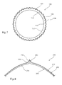
- FIG. 8 this shows in transverse cross-section the structure of balloon wall of a balloon 200 formed using the chamber of Figure 6 .
- the balloon 200 has, in this example, an outermost layer 202 formed from the outer layer 62 of the raw tubing 60 and an inner layer 204 formed from the inner reflow layer 64 of the raw tubing 60.
- the outer layer 202 has formed therein a rib or scoring element 206, at its outer surface 208, with a correspondingly shaped channel in its inner surface 210.
- the outer layer 202 has a generally uniform wall thickness.
- the inner layer 204 has an outer surface 212 which, as a result of its reflow characteristics, has flowed into the recesses in the inner surface 210 of the outer layer 202 of the formed scoring rib 206.
- the inner surface 214 of the inner layer 204 is generally round, having been expanded to this shape by the pressure of the blowing fluid. It will be appreciated that a balloon of Figure 8 will typically have a plurality of scoring elements 206 disposed circumferentially around the balloon.
- the reflow layer 64 of the raw tubing will flow during the balloon forming process into any recesses in the inner wall of the outer layer so as to fill those recesses.
- the reflow material will provide support to the recessed portions of the textured surface or scoring elements, for example, such that upon subsequent inflation of the balloon during its deployment, the outer layer 102, 202 will not stretch and flatten as occurs with prior art structures.
- the inner layer of reflow material is continuous and extends across the entire inner periphery of the balloon chamber, this is not essential. In other embodiments, there may be provided less reflow material and in particular sufficient to fill or substantially fill, the recesses in the outer layer produced by texturing, shaping or other formations in the outer balloon layer.
- the reflow material will not only fill and bind to the outer layer so as to provide support thereto against flattening on inflation of the balloon, but will also help create a generally smooth inner surface to the balloon wall structure such that the inner surface of the balloon will have a minimal cross-sectional dimension in transverse cross-section, which will aid in pressure equalisation across the inner surface of the balloon.
- the manufacturing process produces the balloon structure in a single step, which is therefore fast and efficient. Furthermore, the combination of outer and inner reflow layers need not impair significantly the foldability, wrappability or flexibility of the balloon. In particular, the reflow layer can be thin, not adding significant thickness to the balloon wall.
- body portion of the balloon need not be cylindrical and could, for example, have other shapes such as being tapered from one end to the other, having a waist and so on.
- the texturing could be in the form of shaping to the balloon, for instance with circumferential ribs similar to those of the example of Figure 3A .
Landscapes
- Health & Medical Sciences (AREA)
- Heart & Thoracic Surgery (AREA)
- Life Sciences & Earth Sciences (AREA)
- Engineering & Computer Science (AREA)
- Anesthesiology (AREA)
- Child & Adolescent Psychology (AREA)
- Biophysics (AREA)
- Pulmonology (AREA)
- Biomedical Technology (AREA)
- Hematology (AREA)
- Animal Behavior & Ethology (AREA)
- General Health & Medical Sciences (AREA)
- Public Health (AREA)
- Veterinary Medicine (AREA)
- Manufacturing & Machinery (AREA)
- Media Introduction/Drainage Providing Device (AREA)
- Materials For Medical Uses (AREA)
Applications Claiming Priority (1)
| Application Number | Priority Date | Filing Date | Title |
|---|---|---|---|
| GB1408477.6A GB2526104B (en) | 2014-05-13 | 2014-05-13 | Medical balloon assembly and method of making a medical balloon |
Publications (2)
| Publication Number | Publication Date |
|---|---|
| EP2944347A1 true EP2944347A1 (de) | 2015-11-18 |
| EP2944347B1 EP2944347B1 (de) | 2019-06-19 |
Family
ID=51032697
Family Applications (1)
| Application Number | Title | Priority Date | Filing Date |
|---|---|---|---|
| EP15275029.5A Active EP2944347B1 (de) | 2014-05-13 | 2015-02-10 | Medizinische Ballonanordnung und Verfahren zur Herstellung eines medizinischen Ballons |
Country Status (3)
| Country | Link |
|---|---|
| US (2) | US9993626B2 (de) |
| EP (1) | EP2944347B1 (de) |
| GB (1) | GB2526104B (de) |
Families Citing this family (6)
| Publication number | Priority date | Publication date | Assignee | Title |
|---|---|---|---|---|
| EP3383246A4 (de) | 2015-12-05 | 2019-08-07 | The Regents of the University of Colorado, a body corporate | Neuartige endoskopische vorrichtungen und verfahren zur verwendung davon |
| EP3957350A1 (de) * | 2018-01-03 | 2022-02-23 | C.R. Bard, Inc. | Ballon mit integralem beurteilungselement und zugehörige verfahren |
| US11577056B2 (en) | 2018-01-16 | 2023-02-14 | Aspero Medical, Inc. | Medical devices including textured inflatable balloons |
| US11730928B2 (en) | 2018-01-16 | 2023-08-22 | Aspero Medical, Inc. | Split overtube assembly |
| JP7194459B2 (ja) | 2018-01-16 | 2022-12-22 | ザ リージェンツ オブ ザ ユニバーシティ オブ コロラド,ア ボディー コーポレイト | テクスチャ加工された膨張可能バルーンを含む医療用デバイス |
| JPWO2024106400A1 (de) * | 2022-11-17 | 2024-05-23 |
Citations (4)
| Publication number | Priority date | Publication date | Assignee | Title |
|---|---|---|---|---|
| EP0768097A2 (de) * | 1995-10-11 | 1997-04-16 | Terumo Kabushiki Kaisha | Ballon für Katheter und Ballonkatheter |
| US5833657A (en) * | 1995-05-30 | 1998-11-10 | Ethicon, Inc. | Single-walled balloon catheter with non-linear compliance characteristic |
| US20030055449A1 (en) * | 2001-09-19 | 2003-03-20 | Advanced Cardiovascular Systems, Inc. | MRI visible catheter balloon |
| US20070142772A1 (en) * | 2005-12-16 | 2007-06-21 | Medtronic Vascular, Inc. | Dual-Layer Medical Balloon |
Family Cites Families (13)
| Publication number | Priority date | Publication date | Assignee | Title |
|---|---|---|---|---|
| US5358486A (en) | 1987-01-09 | 1994-10-25 | C. R. Bard, Inc. | Multiple layer high strength balloon for dilatation catheter |
| CA2263492C (en) * | 1996-08-23 | 2006-10-17 | Scimed Life Systems, Inc. | Stent delivery system having stent securement apparatus |
| US5954740A (en) | 1996-09-23 | 1999-09-21 | Boston Scientific Corporation | Catheter balloon having raised radial segments |
| US6706051B2 (en) * | 1998-04-08 | 2004-03-16 | Bhk Holding, Ltd. | Hemostatic system for body cavities |
| US6786889B1 (en) | 1999-03-31 | 2004-09-07 | Scimed Life Systems, Inc | Textured and/or marked balloon for stent delivery |
| AU2002352660A1 (en) * | 2001-11-09 | 2003-05-19 | Novoste Corporation | Balloon catheter with non-slip balloon |
| US7147817B1 (en) * | 2002-12-31 | 2006-12-12 | Advanced Cardiovascular Systems, Inc. | Method of making a low profile balloon |
| US20060182873A1 (en) | 2005-02-17 | 2006-08-17 | Klisch Leo M | Medical devices |
| US7691082B2 (en) | 2005-07-01 | 2010-04-06 | Boston Scientific Scimed, Inc. | Medical devices |
| US7901452B2 (en) | 2007-06-27 | 2011-03-08 | Abbott Cardiovascular Systems Inc. | Method to fabricate a stent having selected morphology to reduce restenosis |
| GB2500628B (en) * | 2012-03-27 | 2016-08-10 | Cook Medical Technologies Llc | Medical balloon with particles therein |
| GB2501065B (en) * | 2012-03-27 | 2014-09-03 | Cook Medical Technologies Llc | Medical balloon with textured or roughened outer layer |
| GB2501243B (en) * | 2012-03-27 | 2014-06-18 | Cook Medical Technologies Llc | Method of making a medical balloon |
-
2014
- 2014-05-13 GB GB1408477.6A patent/GB2526104B/en active Active
-
2015
- 2015-02-10 EP EP15275029.5A patent/EP2944347B1/de active Active
- 2015-05-04 US US14/703,300 patent/US9993626B2/en active Active
-
2018
- 2018-05-10 US US15/976,555 patent/US20180256863A1/en not_active Abandoned
Patent Citations (4)
| Publication number | Priority date | Publication date | Assignee | Title |
|---|---|---|---|---|
| US5833657A (en) * | 1995-05-30 | 1998-11-10 | Ethicon, Inc. | Single-walled balloon catheter with non-linear compliance characteristic |
| EP0768097A2 (de) * | 1995-10-11 | 1997-04-16 | Terumo Kabushiki Kaisha | Ballon für Katheter und Ballonkatheter |
| US20030055449A1 (en) * | 2001-09-19 | 2003-03-20 | Advanced Cardiovascular Systems, Inc. | MRI visible catheter balloon |
| US20070142772A1 (en) * | 2005-12-16 | 2007-06-21 | Medtronic Vascular, Inc. | Dual-Layer Medical Balloon |
Also Published As
| Publication number | Publication date |
|---|---|
| US20150328440A1 (en) | 2015-11-19 |
| GB201408477D0 (en) | 2014-06-25 |
| GB2526104B (en) | 2017-01-11 |
| US20180256863A1 (en) | 2018-09-13 |
| US9993626B2 (en) | 2018-06-12 |
| EP2944347B1 (de) | 2019-06-19 |
| GB2526104A (en) | 2015-11-18 |
Similar Documents
| Publication | Publication Date | Title |
|---|---|---|
| US20180256863A1 (en) | Medical balloon assembly and method of making a medical balloon | |
| US12059534B2 (en) | Inflatable medical balloons with continuous fiber wind | |
| CN106390267B (zh) | 可控制膨胀轮廓气囊覆盖物设备和方法 | |
| EP2990069A1 (de) | Geformter oder texturierter medizinischer ballon | |
| CN106334251B (zh) | 高强度气囊覆盖物和制造方法 | |
| US20090038752A1 (en) | Reinforced balloon for a catheter | |
| EP2644211B1 (de) | Medizinischer ballon mit partikeln darin | |
| JP6901971B2 (ja) | 外側メッシュを有する膨張可能な灌流バルーンおよび関連する方法 | |
| EP2644171B1 (de) | Methode zu Herstellung eines medizinischen Ballons mit texturierter oder angerauter äußeren Schicht | |
| EP3040055B1 (de) | Crimpverfahren und crimpanordnung für endovaskulären stent | |
| CN105120806A (zh) | 带有多褶球囊的聚合物支架 | |
| US9402983B1 (en) | Variably expanding balloon catheter | |
| JP7193360B2 (ja) | バルーンシール応力の軽減並びにそれに関するシステム及び製造方法 | |
| JP5784112B2 (ja) | ステント製造組み立てのための方法及び装置 | |
| JP2019520890A5 (de) | ||
| CA2982109C (en) | Inflatable perfusion balloon with outer mesh and related methods | |
| JP2021133643A (ja) | 空気入りタイヤの製造方法および装置 | |
| CN114728150B (zh) | 球囊导管的制造方法以及树脂制医用球囊的制造装置 | |
| RU2004138078A (ru) | Способ изготовления трубки силиконовой армированной и трубка, изготовленная этим способом |
Legal Events
| Date | Code | Title | Description |
|---|---|---|---|
| PUAI | Public reference made under article 153(3) epc to a published international application that has entered the european phase |
Free format text: ORIGINAL CODE: 0009012 |
|
| AK | Designated contracting states |
Kind code of ref document: A1 Designated state(s): AL AT BE BG CH CY CZ DE DK EE ES FI FR GB GR HR HU IE IS IT LI LT LU LV MC MK MT NL NO PL PT RO RS SE SI SK SM TR |
|
| AX | Request for extension of the european patent |
Extension state: BA ME |
|
| 17P | Request for examination filed |
Effective date: 20160513 |
|
| RBV | Designated contracting states (corrected) |
Designated state(s): AL AT BE BG CH CY CZ DE DK EE ES FI FR GB GR HR HU IE IS IT LI LT LU LV MC MK MT NL NO PL PT RO RS SE SI SK SM TR |
|
| RIC1 | Information provided on ipc code assigned before grant |
Ipc: A61L 29/04 20060101ALI20181126BHEP Ipc: A61L 29/06 20060101ALI20181126BHEP Ipc: A61M 25/10 20130101AFI20181126BHEP |
|
| GRAP | Despatch of communication of intention to grant a patent |
Free format text: ORIGINAL CODE: EPIDOSNIGR1 |
|
| STAA | Information on the status of an ep patent application or granted ep patent |
Free format text: STATUS: GRANT OF PATENT IS INTENDED |
|
| INTG | Intention to grant announced |
Effective date: 20190109 |
|
| RBV | Designated contracting states (corrected) |
Designated state(s): AL AT BE BG CH CY CZ DE DK EE ES FI FR GR HR HU IE IS IT LI LT LU LV MC MK MT NL NO PL PT RO RS SE SI SK SM TR |
|
| GRAS | Grant fee paid |
Free format text: ORIGINAL CODE: EPIDOSNIGR3 |
|
| GRAA | (expected) grant |
Free format text: ORIGINAL CODE: 0009210 |
|
| STAA | Information on the status of an ep patent application or granted ep patent |
Free format text: STATUS: THE PATENT HAS BEEN GRANTED |
|
| AK | Designated contracting states |
Kind code of ref document: B1 Designated state(s): AL AT BE BG CH CY CZ DE DK EE ES FI FR GR HR HU IE IS IT LI LT LU LV MC MK MT NL NO PL PT RO RS SE SI SK SM TR |
|
| REG | Reference to a national code |
Ref country code: CH Ref legal event code: EP |
|
| REG | Reference to a national code |
Ref country code: IE Ref legal event code: FG4D |
|
| REG | Reference to a national code |
Ref country code: AT Ref legal event code: REF Ref document number: 1144700 Country of ref document: AT Kind code of ref document: T Effective date: 20190715 |
|
| REG | Reference to a national code |
Ref country code: DE Ref legal event code: R096 Ref document number: 602015032179 Country of ref document: DE |
|
| REG | Reference to a national code |
Ref country code: NL Ref legal event code: MP Effective date: 20190619 |
|
| PG25 | Lapsed in a contracting state [announced via postgrant information from national office to epo] |
Ref country code: SE Free format text: LAPSE BECAUSE OF FAILURE TO SUBMIT A TRANSLATION OF THE DESCRIPTION OR TO PAY THE FEE WITHIN THE PRESCRIBED TIME-LIMIT Effective date: 20190619 Ref country code: LT Free format text: LAPSE BECAUSE OF FAILURE TO SUBMIT A TRANSLATION OF THE DESCRIPTION OR TO PAY THE FEE WITHIN THE PRESCRIBED TIME-LIMIT Effective date: 20190619 Ref country code: AL Free format text: LAPSE BECAUSE OF FAILURE TO SUBMIT A TRANSLATION OF THE DESCRIPTION OR TO PAY THE FEE WITHIN THE PRESCRIBED TIME-LIMIT Effective date: 20190619 Ref country code: HR Free format text: LAPSE BECAUSE OF FAILURE TO SUBMIT A TRANSLATION OF THE DESCRIPTION OR TO PAY THE FEE WITHIN THE PRESCRIBED TIME-LIMIT Effective date: 20190619 Ref country code: NO Free format text: LAPSE BECAUSE OF FAILURE TO SUBMIT A TRANSLATION OF THE DESCRIPTION OR TO PAY THE FEE WITHIN THE PRESCRIBED TIME-LIMIT Effective date: 20190919 Ref country code: FI Free format text: LAPSE BECAUSE OF FAILURE TO SUBMIT A TRANSLATION OF THE DESCRIPTION OR TO PAY THE FEE WITHIN THE PRESCRIBED TIME-LIMIT Effective date: 20190619 |
|
| REG | Reference to a national code |
Ref country code: LT Ref legal event code: MG4D |
|
| PG25 | Lapsed in a contracting state [announced via postgrant information from national office to epo] |
Ref country code: BG Free format text: LAPSE BECAUSE OF FAILURE TO SUBMIT A TRANSLATION OF THE DESCRIPTION OR TO PAY THE FEE WITHIN THE PRESCRIBED TIME-LIMIT Effective date: 20190919 Ref country code: RS Free format text: LAPSE BECAUSE OF FAILURE TO SUBMIT A TRANSLATION OF THE DESCRIPTION OR TO PAY THE FEE WITHIN THE PRESCRIBED TIME-LIMIT Effective date: 20190619 Ref country code: GR Free format text: LAPSE BECAUSE OF FAILURE TO SUBMIT A TRANSLATION OF THE DESCRIPTION OR TO PAY THE FEE WITHIN THE PRESCRIBED TIME-LIMIT Effective date: 20190920 Ref country code: LV Free format text: LAPSE BECAUSE OF FAILURE TO SUBMIT A TRANSLATION OF THE DESCRIPTION OR TO PAY THE FEE WITHIN THE PRESCRIBED TIME-LIMIT Effective date: 20190619 |
|
| REG | Reference to a national code |
Ref country code: AT Ref legal event code: MK05 Ref document number: 1144700 Country of ref document: AT Kind code of ref document: T Effective date: 20190619 |
|
| PG25 | Lapsed in a contracting state [announced via postgrant information from national office to epo] |
Ref country code: PT Free format text: LAPSE BECAUSE OF FAILURE TO SUBMIT A TRANSLATION OF THE DESCRIPTION OR TO PAY THE FEE WITHIN THE PRESCRIBED TIME-LIMIT Effective date: 20191021 Ref country code: AT Free format text: LAPSE BECAUSE OF FAILURE TO SUBMIT A TRANSLATION OF THE DESCRIPTION OR TO PAY THE FEE WITHIN THE PRESCRIBED TIME-LIMIT Effective date: 20190619 Ref country code: EE Free format text: LAPSE BECAUSE OF FAILURE TO SUBMIT A TRANSLATION OF THE DESCRIPTION OR TO PAY THE FEE WITHIN THE PRESCRIBED TIME-LIMIT Effective date: 20190619 Ref country code: SK Free format text: LAPSE BECAUSE OF FAILURE TO SUBMIT A TRANSLATION OF THE DESCRIPTION OR TO PAY THE FEE WITHIN THE PRESCRIBED TIME-LIMIT Effective date: 20190619 Ref country code: RO Free format text: LAPSE BECAUSE OF FAILURE TO SUBMIT A TRANSLATION OF THE DESCRIPTION OR TO PAY THE FEE WITHIN THE PRESCRIBED TIME-LIMIT Effective date: 20190619 Ref country code: NL Free format text: LAPSE BECAUSE OF FAILURE TO SUBMIT A TRANSLATION OF THE DESCRIPTION OR TO PAY THE FEE WITHIN THE PRESCRIBED TIME-LIMIT Effective date: 20190619 Ref country code: CZ Free format text: LAPSE BECAUSE OF FAILURE TO SUBMIT A TRANSLATION OF THE DESCRIPTION OR TO PAY THE FEE WITHIN THE PRESCRIBED TIME-LIMIT Effective date: 20190619 |
|
| PG25 | Lapsed in a contracting state [announced via postgrant information from national office to epo] |
Ref country code: IS Free format text: LAPSE BECAUSE OF FAILURE TO SUBMIT A TRANSLATION OF THE DESCRIPTION OR TO PAY THE FEE WITHIN THE PRESCRIBED TIME-LIMIT Effective date: 20191019 Ref country code: ES Free format text: LAPSE BECAUSE OF FAILURE TO SUBMIT A TRANSLATION OF THE DESCRIPTION OR TO PAY THE FEE WITHIN THE PRESCRIBED TIME-LIMIT Effective date: 20190619 Ref country code: IT Free format text: LAPSE BECAUSE OF FAILURE TO SUBMIT A TRANSLATION OF THE DESCRIPTION OR TO PAY THE FEE WITHIN THE PRESCRIBED TIME-LIMIT Effective date: 20190619 Ref country code: SM Free format text: LAPSE BECAUSE OF FAILURE TO SUBMIT A TRANSLATION OF THE DESCRIPTION OR TO PAY THE FEE WITHIN THE PRESCRIBED TIME-LIMIT Effective date: 20190619 |
|
| PG25 | Lapsed in a contracting state [announced via postgrant information from national office to epo] |
Ref country code: TR Free format text: LAPSE BECAUSE OF FAILURE TO SUBMIT A TRANSLATION OF THE DESCRIPTION OR TO PAY THE FEE WITHIN THE PRESCRIBED TIME-LIMIT Effective date: 20190619 |
|
| PG25 | Lapsed in a contracting state [announced via postgrant information from national office to epo] |
Ref country code: PL Free format text: LAPSE BECAUSE OF FAILURE TO SUBMIT A TRANSLATION OF THE DESCRIPTION OR TO PAY THE FEE WITHIN THE PRESCRIBED TIME-LIMIT Effective date: 20190619 Ref country code: DK Free format text: LAPSE BECAUSE OF FAILURE TO SUBMIT A TRANSLATION OF THE DESCRIPTION OR TO PAY THE FEE WITHIN THE PRESCRIBED TIME-LIMIT Effective date: 20190619 |
|
| PG25 | Lapsed in a contracting state [announced via postgrant information from national office to epo] |
Ref country code: IS Free format text: LAPSE BECAUSE OF FAILURE TO SUBMIT A TRANSLATION OF THE DESCRIPTION OR TO PAY THE FEE WITHIN THE PRESCRIBED TIME-LIMIT Effective date: 20200224 |
|
| REG | Reference to a national code |
Ref country code: DE Ref legal event code: R097 Ref document number: 602015032179 Country of ref document: DE |
|
| PLBE | No opposition filed within time limit |
Free format text: ORIGINAL CODE: 0009261 |
|
| STAA | Information on the status of an ep patent application or granted ep patent |
Free format text: STATUS: NO OPPOSITION FILED WITHIN TIME LIMIT |
|
| PG2D | Information on lapse in contracting state deleted |
Ref country code: IS |
|
| 26N | No opposition filed |
Effective date: 20200603 |
|
| PG25 | Lapsed in a contracting state [announced via postgrant information from national office to epo] |
Ref country code: SI Free format text: LAPSE BECAUSE OF FAILURE TO SUBMIT A TRANSLATION OF THE DESCRIPTION OR TO PAY THE FEE WITHIN THE PRESCRIBED TIME-LIMIT Effective date: 20190619 |
|
| REG | Reference to a national code |
Ref country code: CH Ref legal event code: PL |
|
| REG | Reference to a national code |
Ref country code: BE Ref legal event code: MM Effective date: 20200229 |
|
| PG25 | Lapsed in a contracting state [announced via postgrant information from national office to epo] |
Ref country code: LU Free format text: LAPSE BECAUSE OF NON-PAYMENT OF DUE FEES Effective date: 20200210 Ref country code: MC Free format text: LAPSE BECAUSE OF FAILURE TO SUBMIT A TRANSLATION OF THE DESCRIPTION OR TO PAY THE FEE WITHIN THE PRESCRIBED TIME-LIMIT Effective date: 20190619 |
|
| PG25 | Lapsed in a contracting state [announced via postgrant information from national office to epo] |
Ref country code: LI Free format text: LAPSE BECAUSE OF NON-PAYMENT OF DUE FEES Effective date: 20200229 Ref country code: CH Free format text: LAPSE BECAUSE OF NON-PAYMENT OF DUE FEES Effective date: 20200229 |
|
| PG25 | Lapsed in a contracting state [announced via postgrant information from national office to epo] |
Ref country code: FR Free format text: LAPSE BECAUSE OF NON-PAYMENT OF DUE FEES Effective date: 20200229 |
|
| PG25 | Lapsed in a contracting state [announced via postgrant information from national office to epo] |
Ref country code: BE Free format text: LAPSE BECAUSE OF NON-PAYMENT OF DUE FEES Effective date: 20200229 |
|
| PG25 | Lapsed in a contracting state [announced via postgrant information from national office to epo] |
Ref country code: MT Free format text: LAPSE BECAUSE OF FAILURE TO SUBMIT A TRANSLATION OF THE DESCRIPTION OR TO PAY THE FEE WITHIN THE PRESCRIBED TIME-LIMIT Effective date: 20190619 Ref country code: CY Free format text: LAPSE BECAUSE OF FAILURE TO SUBMIT A TRANSLATION OF THE DESCRIPTION OR TO PAY THE FEE WITHIN THE PRESCRIBED TIME-LIMIT Effective date: 20190619 |
|
| PG25 | Lapsed in a contracting state [announced via postgrant information from national office to epo] |
Ref country code: MK Free format text: LAPSE BECAUSE OF FAILURE TO SUBMIT A TRANSLATION OF THE DESCRIPTION OR TO PAY THE FEE WITHIN THE PRESCRIBED TIME-LIMIT Effective date: 20190619 |
|
| P01 | Opt-out of the competence of the unified patent court (upc) registered |
Effective date: 20230602 |
|
| PGFP | Annual fee paid to national office [announced via postgrant information from national office to epo] |
Ref country code: DE Payment date: 20260220 Year of fee payment: 12 Ref country code: IE Payment date: 20260219 Year of fee payment: 12 |