EP2944355A1 - Mischanordnung für eine Brandbekämpfungsvorrichtung, Brandbekämpfungsvorrichtung, und Verfahren zum Mischen von Brandlöschflüssigkeit und Schäumungsmittel - Google Patents
Mischanordnung für eine Brandbekämpfungsvorrichtung, Brandbekämpfungsvorrichtung, und Verfahren zum Mischen von Brandlöschflüssigkeit und Schäumungsmittel Download PDFInfo
- Publication number
- EP2944355A1 EP2944355A1 EP14001745.0A EP14001745A EP2944355A1 EP 2944355 A1 EP2944355 A1 EP 2944355A1 EP 14001745 A EP14001745 A EP 14001745A EP 2944355 A1 EP2944355 A1 EP 2944355A1
- Authority
- EP
- European Patent Office
- Prior art keywords
- flow axis
- mixing
- fluid
- section
- mixing assembly
- Prior art date
- Legal status (The legal status is an assumption and is not a legal conclusion. Google has not performed a legal analysis and makes no representation as to the accuracy of the status listed.)
- Granted
Links
Images


Classifications
-
- A—HUMAN NECESSITIES
- A62—LIFE-SAVING; FIRE-FIGHTING
- A62C—FIRE-FIGHTING
- A62C5/00—Making of fire-extinguishing materials immediately before use
- A62C5/02—Making of fire-extinguishing materials immediately before use of foam
-
- A—HUMAN NECESSITIES
- A62—LIFE-SAVING; FIRE-FIGHTING
- A62C—FIRE-FIGHTING
- A62C5/00—Making of fire-extinguishing materials immediately before use
- A62C5/002—Apparatus for mixing extinguishants with water
Definitions
- the present disclosure generally relates to the field of firefighting devices.
- a firefighting device configured to mix a fire extinguishing fluid with a foaming agent are described.
- Water has long been used for extinguishing fires. There exist nevertheless many situations in which water is not the best choice. Water is typically not effective for extinguishing burning oil and similar non-polar substances. For such substances, firefighting foams have been developed.
- Aqueous Film Forming Foam also called AFFF or A3F
- AFFF is foam made by mixing water and a synthetic foaming agent.
- the resulting foam typically comprises 1 to 6 liters of foaming agent per 100 liters of mixture.
- the mixture of water and foaming agent can be produced prior to its use and stored in a tank of a firefighting device until a fire has to be extinguished.
- Other firefighting devices are configured to produce the mixture during the firefighting process.
- EP 1 595 579 A2 discloses a firefighting device of the latter type.
- the firefighting device of EP1 595 579 comprises a pump for producing pressurized water and an injector for injecting the foaming agent into the pressurized water so as to mix water and foaming agent.
- the injector is realized as a differential pressure injector of the Venturi type and arranged in a mixing section of the firefighting device downstream of the water pump.
- Differential pressure injectors typically comprise a linear pipe with a first pipe section having a decreasing cross sectional area followed by a second pipe section of increasing cross sectional area.
- the water is accelerated along the first pipe section.
- the static pressure in the region of smallest cross sectional area i.e., in the region between the outlet of the first pipe section and the inlet of the second pipe section
- the resulting pressure difference leads to a suction effect in the region of smallest cross sectional area. This suction effect is exploited for injecting the foaming agent into the flow of pressurized water.
- differential pressure injectors attributes to the axial extension of the firefighting device. For this reason conventional firefighting devices with differential pressure injectors have a certain minimum length that cannot be decreased further without decreasing the size of other components such as, for example, the pump or its motor. Due to prevailing pressure requirements it is, however, often not possible to downsize those components, so that firefighting devices with a differential pressure injector can become quite bulky. This drawback is particularly pronounced when the firefighting device is to be realized as a mobile device.
- a mixing assembly for a firefighting device.
- the mixing assembly comprises an inlet configured to receive pressurized fire extinguishing fluid from a pump of the firefighting device, wherein the fluid is received along a first flow axis.
- the mixing assembly further comprises a first mixing section with a first differential pressure injector configured to accelerate the fluid along a second fluid axis arranged at a first angle relative to the first flow axis and to inject a foaming agent in the fluid, thereby producing a mixture of the fluid and the foaming agent.
- the mixing assembly comprises at least one outlet configured to deliver the mixture along a third flow axis, wherein the third flow axis is arranged at a second angle relative to the second flow axis.
- Each of the first angle and the second angle lies approximately between 60 degrees and 120 degrees.
- the second flow axis may be offset relative to one or both of the first flow axis and the third flow axis.
- the second flow axis may, but need not, intersect one or both of the first flow axis and the third flow axis.
- the inlet may be in fluid communication with the first mixing section.
- the first mixing section may be in fluid communication with the at least one outlet.
- One or multiple connecting sections may be arranged between the inlet and the first mixing section and between the first mixing section and the at least one outlet.
- the first flow axis may approximately be parallel to the third flow axis.
- the angle between the first flow axis and the third flow axis may be less than approximately 30 degrees.
- the first flow axis and the third flow axis may lie within a single plane.
- Each of the first angle and the second angle may lie approximately between 80 degrees and 100 degrees. As an example, at least one of the first angle and the second angle may approximately be 90 degrees. Generally, the second flow axis may approximately be perpendicular to each of the first flow axis and the third flow axis (e.g., within an angular range of approximately 85 degrees to 95 degrees).
- the mixing assembly may further comprise a second mixing section coupled between the inlet and the at least one outlet.
- the second mixing section may comprise a second differential pressure injector configured to accelerate the fluid along a fourth flow axis and to inject a foaming agent in the fluid, thereby producing a mixture of the fluid and the foaming agent.
- the fourth flow axis may be arranged at the first angle relative to the first flow axis.
- the fourth flow axis may approximately be parallel to the second flow axis.
- the angle between the fourth flow axis and the second flow axis may be less than approximately 30 degrees.
- the fourth flow axis and the second flow axis may lie within a single plane.
- a fluid splitting section may be arranged between the input and each of the first mixing section and the second mixing section.
- the fluid splitting section may have a T configuration.
- the fluid splitting section may be configured to split the pressurized fluid received via the inlet in a first fluid portion towards the first mixing section and a second fluid portion towards the second mixing section.
- the first fluid portion and the second fluid portion are approximately equal.
- the first fluid portion and the second fluid portion are different.
- the mixing assembly may comprise more than two mixing sections.
- the fluid splitting portion section may be configured to split the pressurized fluid in three or more fluid portions.
- the mixing assembly may comprise a mixture combining section arranged between each of the first mixing section and the second mixing section (and any further mixing section) on the one hand and, on the other hand, the at least one output.
- the mixture combining section may have a T configuration.
- the mixture combining section may be configured to combine the mixtures of fluid and foaming agent received from each mixing section. The combined mixtures may then be delivered via the one or more outlets.
- the first mixing section, the second mixing section, the fluid splitting section and the fluid combining section may essentially form a rectangular (e.g., quadratic) arrangement. As such, the first mixing section, the second mixing section, the fluid mixing section and the fluid combining section may essentially lie within a single plane.
- the mixing assembly may further comprise a first connection section between the inlet and the first mixing section.
- the first connection section may have a first bend relative to the first flow axis and a second bend relative to the first flow axis downstream of the first bend.
- the first flow axis and the first bend of the first connection section may essentially lie within a first plane.
- the second bend of the first connection portion and the second flow axis may essentially lie within a second plane intersecting the first plane.
- the first plane may extend essentially perpendicular (e.g., at an angle between 85 degrees and 95 degrees) to the second plane.
- the mixing assembly may further comprise a second connection section between the first mixing section and the at least one outlet.
- the second connection section may have a first bend relative to the third flow axis and a second bend relative to the third flow axis downstream of the first bend.
- the second flow axis and the first bend of the second connection section may essentially lie within a third plane.
- the second bend of the second connection section and the third flow axis may essentially lie within a fourth plane intersecting the third plane.
- the third plane may extend essentially perpendicular (e.g., at an angle between 85 degrees and 95 degrees) to the fourth plane.
- a firefighting device comprising a pump and the mixing assembly presented herein, wherein the inlet of the mixing assembly is coupled to the pump.
- the inlet may be coupled to an outlet of the pump.
- a pipe or pipe system may be used to couple the inlet of the mixing assembly to the pump outlet.
- the pump may define a pump axis.
- the pump axis may be defined by an axial extension of a rotating member (e.g., a spindle of a pump motor or gear stage) that drives the pump.
- the pump axis may be defined by the extension of a pump piston pressurizing the fluid.
- the second flow axis extends essentially perpendicular (e.g., at an angle between 85 degrees and 95 degrees) to the pump axis.
- the firefighting device may be a mobile device.
- the firefighting device may be portable and/or may be configured to be mounted on a cart with two or more wheels.
- a method of mixing a fire extinguishing fluid and a foaming agent in a firefighting device comprises pressurizing the fluid, receiving the pressurized fluid along a first flow axis, and accelerating the fluid by a differential pressure injector along a second flow axis arranged at a first angle relative to the first flow axis and injecting a foaming agent in the fluid, thereby producing a mixture of the fluid and the foaming agent.
- the method further comprises delivering the mixture along a third flow axis, wherein the third flow axis is arranged at a second angle relative to the first flow axis.
- Each of the first angle and the second angle lies approximately between 60 degrees and 120 degrees.
- the method may be performed by a firefighting device as presented herein.
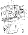
- Fig. 1 illustrates an embodiment of a firefighting system 100 comprising a mobile firefighting device 102 and a reservoir 104 for a liquid foaming agent such as AFFF.
- the reservoir 104 is coupled via a hose 106 to the firefighting device 102.
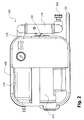
- Figs. 2 and 3 show different views of the firefighting device 102, wherein the reservoir 104 has not been depicted.
- the firefighting device 102 of Figs. 1 to 3 comprises a pump 108 with a pump inlet 110.
- the pump inlet 110 has a coupling configured to be coupled to a water hose.
- the firefighting 102 further comprises a pump motor 112 configured to operate the pump 108.
- the motor 112 is realized as an internal combustion motor.
- a fuel tank 114 for the motor 112 is integrated into the firefighting device 102. It will be appreciated that in other embodiments the motor 112 can be an electric motor, in which case the fuel tank 114 could be omitted.
- the firefighting device 102 comprises a mixing assembly 116.
- the mixing assembly 116 has a fluid inlet 118 coupled to a fluid outlet 120 of the pump 108.
- the mixing assembly 116 further comprises two fluid outlets 122.
- the fluid outlets 122 are, in a present example, configured with Storz-D couplings. It will be appreciated that an alternative coupling type could be used as well.
- the mixing assembly 116 only a single outlet 122 or more than two outlets 122 may be used.
- the mixing assembly 116 further comprises two mixing sections 124, 126 arranged between the fluid inlet 118 and the fluid outlets 122.
- Each mixing section 124, 126 comprises a differential pressure injector (not shown) configured to inject foaming agent from the reservoir 104 into a water stream accelerated along the respective injector.
- each mixing section 124, 126 i.e., each injector
- the various components of the mobile firefighting device 102 described above are rigidly coupled to each other and supported in a rack 128 with a handle 132.
- the rack 128 may be provided with wheels (not shown) to form a cart. In other variants, the wheels may be omitted, but the firefighting device 102 may remain portable.
- the inlet 118 of the mixing assembly 116 is configured to receive pressurized water from the pump 108 along a flow axis 140.
- the flow axis 140 is essentially defined by a straight pipe section connecting the inlet 118 with a fluid splitting section 142 of the mixing assembly 116.
- the fluid splitting section 142 has a T configuration to split, or divert, the pressurized water received along the flow axis 140 into two portions, or streams, along a flow axis 144.
- the flow axis 144 extends perpendicular to the flow axis 140 along which the fluid is received from the pump 140.
- a first water portion is thus directed via a first bend of 90 degrees in the fluid splitting section 142 towards the first mixing section 124 and a second water portion is directed via a second bend in the fluid splitting section 142 in the opposite direction towards the second mixing section 126. Then, at a third bend of 90 degrees downstream the first bend, the first water portion is fed to the first mixing section 124. In a similar manner, the second water portion is fed via a fourth bend of 90 degrees downstream the second bend to the second mixing section 126.
- Each of the mixing sections 124, 126 comprises a differential pressure injector 146 of the Venturi type as exemplarily shown for mixing section 124 in Fig. 7 .
- the differential pressure injector 146 comprises in a conventional manner a linear arrangement of a first pipe section having a decreasing cross sectional area followed by a second pipe section of increasing cross sectional area. In the region of smallest cross sectional area between the first pipe section and the second pipe section an injection inlet 148 for the foaming agent is arranged.
- the injection inlet 148 is configured to be coupled to the hose 106 that leads to the reservoir 104 (see Fig. 1 ).
- the injector 146 further comprises an adjustment element 150 configured to adjust the amount of foaming agent injected in the pressurized water flow.
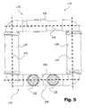
- the injectors 146 in the two mixing sections 124, 126 are configured to accelerate the pressurized water along a respective flow axis 152, 154 that is collinear with an axial extension of the corresponding mixing section 124, 126.
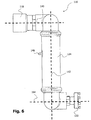
- the corresponding axis 152, 154 is arranged at an angle of 90 degrees relative to the axes 140, 144. As can be seen from Figs. 4 to 6 , the axes 144, 152 and 154 lie within a first plane and the axes 140 and 144 lie within a second plane that extends perpendicular to the first plane.
- the mixtures of water and foaming agent produced in the mixing sections 124, 126 are deflected by a respective bend of 90 degrees at the downstream end of each mixing section 124, 126 towards each other along an axis 156.
- the two mixtures are then combined at a mixture combining section 158 arranged approximately in the middle between the two mixing sections 124, 126.
- the mixture combining section 158 the resulting combined mixture is deflected at a respective bend of 90 degrees towards the two outlets 122.
- Each outlet 122 defines a further flow axis 146 that is arranged perpendicular to and offset from the flow axes 152, 154 defined by the injectors 146.
- the axes 144, 152, 154 and 156 lie within a single plane.
- the fluid splitting section 142, the two mixing sections 124, 126 and the mixture combining section 158 form a rectangular pipe structure that is likewise located within a single plane.
- the plane defined by the axes 142, 152, 154 and 156 extends perpendicular to the plane defined by the axes 156 and 164 and to the plane defined by the axes 140 and 144.
- the plane defined by the axes 156 and 164 extends at a certain offset defined by the length of the mixing sections 124, 126 parallel to the plane defined by the axes 140 and 144.
- the two outlets 122 may be combined into a single outlet.
- This single outlet may have a larger cross sectional area than each of the two outlets 122.
- the inlet 118 of the mixing assembly 116 is connected to the mixing section 124 via a first connection section 170 that has a first bend relative to the first flow axis 140 (towards the flow axis 144) and a further bend relative to the first flow axis 140 (from the flow axis 144 towards the flow axis 152) downstream of the first bend.
- a second connection section 172 can be identified between the mixing section 124 and the outlets 122.
- the second connection section 172 has a first bend relative to the flow axis 164 (from the axis 152 towards the axis 156) and a further bend relative to the flow axis 164 (from the flow axis 156 towards the flow axis 164) downstream of the first bend. Similar connection sections may be identified for the other mixing section 126.
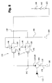
- Fig. 8 shows an equivalent fluid circuit of the firefighting system 100 of Fig. 1
- Fig. 9 shows a diagram of a method illustrating the operational principle of the firefighting system 100.
- the pump 108 is operated upon starting the motor 112 and draws in water via water inlet 110.
- the water may be drawn in via a hose 178 coupled to a water supply 180.
- the motor 112 is typically operated at up to 3500 or 4000 rpm, and the pump 108 typically draws in 500 l/min.
- the pump 108 pressurizes the water (step 902 in Fig. 9 ) and outputs the pressurized water via its outlet 120.
- the pressurized water is received at the inlet 118 of the mixing assembly 116 along the axis 140 (step 904).
- the pressurized water received via the inlet 118 of the mixing assembly 116 is split at the fluid splitting section 142 into two pressurized water portions that are fed to the two mixing sections 124, 126, respectively.
- the pressurized water is accelerated by the injectors 146 along the flow axes 152, 154, respectively.
- the injectors 146 inject foaming agent from the reservoir 104 in the accelerated fluid portions, thereby producing a mixture of the fluid and the foaming agent (step 906).
- the mixing ratio of each injector 146 can be adjusted via the adjustment element 150 (see Fig. 4 ).
- the resulting mixture may comprise 3 to 4 liters of foaming agent per 100 liter of the mixture.
- the mixtures generated by the injectors 146 are then combined at the mixture combining section 158 and delivered along flow axes 164 via the outlets 122 (step 908).
- the outlets 122 are connected via a dedicated hose to a conventional firefighting pistol that comprises a shut-off valve 182 as well as a flow control valve 184 with a fixed or adjustable orifice.
- the axial extension of the injector 146 is not aligned with (i.e., parallel to) the axes 140, 164 along which the pressurized water is received and along which the resulting mixture is delivered. Rather, the flow axes 152, 154 defined by the injectors 146 have an oblige extension relative to the axes 140, 164. As such, the axial extension of the mixing assembly 116, and of the firefighting device 102 as a whole, can be reduced. The maximum length reduction is obtained when the axes 152, 154 are arranged perpendicular to the axes 140, 164. It will be appreciated that a substantial length reduction is still obtained at angles between the axes 152, 154 on the one hand and the axes 140, 164 on the other hand that lie approximately between 60 degrees and 120 degrees.
- two mixing sections 124, 126 are provided. It will be appreciated that in other embodiments the mixing assembly 116 may comprise only one mixing section. In such a case the axis defined by the injector arranged within the mixing section may intercept the axis along which the fluid is received and the axis along which the mixture is delivered.
- the provision of two or more mixing sections permits to efficiently increase the volume of foaming agent that can be injected in the pressurized water delivered by the pump 108.
Landscapes
- Health & Medical Sciences (AREA)
- Public Health (AREA)
- Business, Economics & Management (AREA)
- Emergency Management (AREA)
- Accessories For Mixers (AREA)
- Nozzles (AREA)
Priority Applications (1)
| Application Number | Priority Date | Filing Date | Title |
|---|---|---|---|
| EP14001745.0A EP2944355B1 (de) | 2014-05-16 | 2014-05-16 | Mischanordnung für eine Brandbekämpfungsvorrichtung, Brandbekämpfungsvorrichtung, und Verfahren zum Mischen von Brandlöschflüssigkeit und Schäumungsmittel |
Applications Claiming Priority (1)
| Application Number | Priority Date | Filing Date | Title |
|---|---|---|---|
| EP14001745.0A EP2944355B1 (de) | 2014-05-16 | 2014-05-16 | Mischanordnung für eine Brandbekämpfungsvorrichtung, Brandbekämpfungsvorrichtung, und Verfahren zum Mischen von Brandlöschflüssigkeit und Schäumungsmittel |
Publications (2)
| Publication Number | Publication Date |
|---|---|
| EP2944355A1 true EP2944355A1 (de) | 2015-11-18 |
| EP2944355B1 EP2944355B1 (de) | 2021-11-03 |
Family
ID=50732750
Family Applications (1)
| Application Number | Title | Priority Date | Filing Date |
|---|---|---|---|
| EP14001745.0A Active EP2944355B1 (de) | 2014-05-16 | 2014-05-16 | Mischanordnung für eine Brandbekämpfungsvorrichtung, Brandbekämpfungsvorrichtung, und Verfahren zum Mischen von Brandlöschflüssigkeit und Schäumungsmittel |
Country Status (1)
| Country | Link |
|---|---|
| EP (1) | EP2944355B1 (de) |
Citations (2)
| Publication number | Priority date | Publication date | Assignee | Title |
|---|---|---|---|---|
| EP1595579A2 (de) | 2004-04-30 | 2005-11-16 | Andreas Dipl.-Ing.(FH) Vigh | Löscheinrichtung zur Brandbekämpfung mit einer Schaumzumischvorrichtung |
| US20060151184A1 (en) * | 2001-11-20 | 2006-07-13 | Boyle Thomas J | System and method for testing foam-water fire fighting and fire suppression systems |
-
2014
- 2014-05-16 EP EP14001745.0A patent/EP2944355B1/de active Active
Patent Citations (2)
| Publication number | Priority date | Publication date | Assignee | Title |
|---|---|---|---|---|
| US20060151184A1 (en) * | 2001-11-20 | 2006-07-13 | Boyle Thomas J | System and method for testing foam-water fire fighting and fire suppression systems |
| EP1595579A2 (de) | 2004-04-30 | 2005-11-16 | Andreas Dipl.-Ing.(FH) Vigh | Löscheinrichtung zur Brandbekämpfung mit einer Schaumzumischvorrichtung |
Also Published As
| Publication number | Publication date |
|---|---|
| EP2944355B1 (de) | 2021-11-03 |
Similar Documents
| Publication | Publication Date | Title |
|---|---|---|
| US9901943B2 (en) | Pressure washer gun with chemical injection and foaming capabilities | |
| AU2010249197B2 (en) | Foam soap generator | |
| CN107107080B (zh) | 雾化器喷嘴 | |
| US4993495A (en) | Apparatus for applying firefighting chemicals | |
| US20140352985A1 (en) | Self-Regulating Foam Dispensing System | |
| CN112236219B (zh) | 微细气泡生成装置 | |
| NZ212110A (en) | Mixing foamant with water by venturi effect in pump bypass | |
| US20230058407A1 (en) | Nanobubble Nozzle | |
| EP2964961A1 (de) | Saugstrahlpumpe | |
| US20120305272A1 (en) | Foam generating device for fire hoses | |
| US20140224895A1 (en) | Air driven dispenser for delivery of undiluted chemical | |
| EP3092065B1 (de) | Vormischer und zugehörige installation | |
| US3467314A (en) | Apparatus for cleaning objects | |
| US20120132730A1 (en) | Enhanced Nozzle Body | |
| US20170259091A1 (en) | Fire-fighting system | |
| KR20130052984A (ko) | 액상 약제 살포용 분무장치의 분사관 | |
| US9364697B2 (en) | Foam-applying nozzle | |
| EP2944355B1 (de) | Mischanordnung für eine Brandbekämpfungsvorrichtung, Brandbekämpfungsvorrichtung, und Verfahren zum Mischen von Brandlöschflüssigkeit und Schäumungsmittel | |
| US20120247790A1 (en) | Foam propellant system | |
| AT511466A4 (de) | Fluidmischer | |
| US20070137716A1 (en) | Foam eductor | |
| WO2005018824A1 (fr) | Procede de formation d'un jet de gouttelettes de gaz en deux phases et dispositif de sa mise en oeuvre | |
| CN212548083U (zh) | 一种穿墙灭火装置 | |
| US8561972B2 (en) | Low pressure gas transfer device | |
| US11691041B1 (en) | Compressed air foam mixing device |
Legal Events
| Date | Code | Title | Description |
|---|---|---|---|
| PUAI | Public reference made under article 153(3) epc to a published international application that has entered the european phase |
Free format text: ORIGINAL CODE: 0009012 |
|
| AK | Designated contracting states |
Kind code of ref document: A1 Designated state(s): AL AT BE BG CH CY CZ DE DK EE ES FI FR GB GR HR HU IE IS IT LI LT LU LV MC MK MT NL NO PL PT RO RS SE SI SK SM TR |
|
| AX | Request for extension of the european patent |
Extension state: BA ME |
|
| 17P | Request for examination filed |
Effective date: 20160425 |
|
| RBV | Designated contracting states (corrected) |
Designated state(s): AL AT BE BG CH CY CZ DE DK EE ES FI FR GB GR HR HU IE IS IT LI LT LU LV MC MK MT NL NO PL PT RO RS SE SI SK SM TR |
|
| GRAP | Despatch of communication of intention to grant a patent |
Free format text: ORIGINAL CODE: EPIDOSNIGR1 |
|
| STAA | Information on the status of an ep patent application or granted ep patent |
Free format text: STATUS: GRANT OF PATENT IS INTENDED |
|
| INTG | Intention to grant announced |
Effective date: 20210528 |
|
| GRAS | Grant fee paid |
Free format text: ORIGINAL CODE: EPIDOSNIGR3 |
|
| GRAA | (expected) grant |
Free format text: ORIGINAL CODE: 0009210 |
|
| STAA | Information on the status of an ep patent application or granted ep patent |
Free format text: STATUS: THE PATENT HAS BEEN GRANTED |
|
| AK | Designated contracting states |
Kind code of ref document: B1 Designated state(s): AL AT BE BG CH CY CZ DE DK EE ES FI FR GB GR HR HU IE IS IT LI LT LU LV MC MK MT NL NO PL PT RO RS SE SI SK SM TR |
|
| REG | Reference to a national code |
Ref country code: GB Ref legal event code: FG4D |
|
| REG | Reference to a national code |
Ref country code: AT Ref legal event code: REF Ref document number: 1443448 Country of ref document: AT Kind code of ref document: T Effective date: 20211115 Ref country code: CH Ref legal event code: EP |
|
| REG | Reference to a national code |
Ref country code: IE Ref legal event code: FG4D |
|
| REG | Reference to a national code |
Ref country code: DE Ref legal event code: R096 Ref document number: 602014080987 Country of ref document: DE |
|
| REG | Reference to a national code |
Ref country code: LT Ref legal event code: MG9D |
|
| REG | Reference to a national code |
Ref country code: NL Ref legal event code: MP Effective date: 20211103 |
|
| REG | Reference to a national code |
Ref country code: AT Ref legal event code: MK05 Ref document number: 1443448 Country of ref document: AT Kind code of ref document: T Effective date: 20211103 |
|
| PG25 | Lapsed in a contracting state [announced via postgrant information from national office to epo] |
Ref country code: RS Free format text: LAPSE BECAUSE OF FAILURE TO SUBMIT A TRANSLATION OF THE DESCRIPTION OR TO PAY THE FEE WITHIN THE PRESCRIBED TIME-LIMIT Effective date: 20211103 Ref country code: LT Free format text: LAPSE BECAUSE OF FAILURE TO SUBMIT A TRANSLATION OF THE DESCRIPTION OR TO PAY THE FEE WITHIN THE PRESCRIBED TIME-LIMIT Effective date: 20211103 Ref country code: FI Free format text: LAPSE BECAUSE OF FAILURE TO SUBMIT A TRANSLATION OF THE DESCRIPTION OR TO PAY THE FEE WITHIN THE PRESCRIBED TIME-LIMIT Effective date: 20211103 Ref country code: BG Free format text: LAPSE BECAUSE OF FAILURE TO SUBMIT A TRANSLATION OF THE DESCRIPTION OR TO PAY THE FEE WITHIN THE PRESCRIBED TIME-LIMIT Effective date: 20220203 Ref country code: AT Free format text: LAPSE BECAUSE OF FAILURE TO SUBMIT A TRANSLATION OF THE DESCRIPTION OR TO PAY THE FEE WITHIN THE PRESCRIBED TIME-LIMIT Effective date: 20211103 |
|
| PG25 | Lapsed in a contracting state [announced via postgrant information from national office to epo] |
Ref country code: IS Free format text: LAPSE BECAUSE OF FAILURE TO SUBMIT A TRANSLATION OF THE DESCRIPTION OR TO PAY THE FEE WITHIN THE PRESCRIBED TIME-LIMIT Effective date: 20220303 Ref country code: SE Free format text: LAPSE BECAUSE OF FAILURE TO SUBMIT A TRANSLATION OF THE DESCRIPTION OR TO PAY THE FEE WITHIN THE PRESCRIBED TIME-LIMIT Effective date: 20211103 Ref country code: PT Free format text: LAPSE BECAUSE OF FAILURE TO SUBMIT A TRANSLATION OF THE DESCRIPTION OR TO PAY THE FEE WITHIN THE PRESCRIBED TIME-LIMIT Effective date: 20220303 Ref country code: PL Free format text: LAPSE BECAUSE OF FAILURE TO SUBMIT A TRANSLATION OF THE DESCRIPTION OR TO PAY THE FEE WITHIN THE PRESCRIBED TIME-LIMIT Effective date: 20211103 Ref country code: NO Free format text: LAPSE BECAUSE OF FAILURE TO SUBMIT A TRANSLATION OF THE DESCRIPTION OR TO PAY THE FEE WITHIN THE PRESCRIBED TIME-LIMIT Effective date: 20220203 Ref country code: NL Free format text: LAPSE BECAUSE OF FAILURE TO SUBMIT A TRANSLATION OF THE DESCRIPTION OR TO PAY THE FEE WITHIN THE PRESCRIBED TIME-LIMIT Effective date: 20211103 Ref country code: LV Free format text: LAPSE BECAUSE OF FAILURE TO SUBMIT A TRANSLATION OF THE DESCRIPTION OR TO PAY THE FEE WITHIN THE PRESCRIBED TIME-LIMIT Effective date: 20211103 Ref country code: HR Free format text: LAPSE BECAUSE OF FAILURE TO SUBMIT A TRANSLATION OF THE DESCRIPTION OR TO PAY THE FEE WITHIN THE PRESCRIBED TIME-LIMIT Effective date: 20211103 Ref country code: GR Free format text: LAPSE BECAUSE OF FAILURE TO SUBMIT A TRANSLATION OF THE DESCRIPTION OR TO PAY THE FEE WITHIN THE PRESCRIBED TIME-LIMIT Effective date: 20220204 Ref country code: ES Free format text: LAPSE BECAUSE OF FAILURE TO SUBMIT A TRANSLATION OF THE DESCRIPTION OR TO PAY THE FEE WITHIN THE PRESCRIBED TIME-LIMIT Effective date: 20211103 |
|
| PG25 | Lapsed in a contracting state [announced via postgrant information from national office to epo] |
Ref country code: SM Free format text: LAPSE BECAUSE OF FAILURE TO SUBMIT A TRANSLATION OF THE DESCRIPTION OR TO PAY THE FEE WITHIN THE PRESCRIBED TIME-LIMIT Effective date: 20211103 Ref country code: SK Free format text: LAPSE BECAUSE OF FAILURE TO SUBMIT A TRANSLATION OF THE DESCRIPTION OR TO PAY THE FEE WITHIN THE PRESCRIBED TIME-LIMIT Effective date: 20211103 Ref country code: RO Free format text: LAPSE BECAUSE OF FAILURE TO SUBMIT A TRANSLATION OF THE DESCRIPTION OR TO PAY THE FEE WITHIN THE PRESCRIBED TIME-LIMIT Effective date: 20211103 Ref country code: EE Free format text: LAPSE BECAUSE OF FAILURE TO SUBMIT A TRANSLATION OF THE DESCRIPTION OR TO PAY THE FEE WITHIN THE PRESCRIBED TIME-LIMIT Effective date: 20211103 Ref country code: DK Free format text: LAPSE BECAUSE OF FAILURE TO SUBMIT A TRANSLATION OF THE DESCRIPTION OR TO PAY THE FEE WITHIN THE PRESCRIBED TIME-LIMIT Effective date: 20211103 Ref country code: CZ Free format text: LAPSE BECAUSE OF FAILURE TO SUBMIT A TRANSLATION OF THE DESCRIPTION OR TO PAY THE FEE WITHIN THE PRESCRIBED TIME-LIMIT Effective date: 20211103 |
|
| REG | Reference to a national code |
Ref country code: DE Ref legal event code: R097 Ref document number: 602014080987 Country of ref document: DE |
|
| PLBE | No opposition filed within time limit |
Free format text: ORIGINAL CODE: 0009261 |
|
| STAA | Information on the status of an ep patent application or granted ep patent |
Free format text: STATUS: NO OPPOSITION FILED WITHIN TIME LIMIT |
|
| 26N | No opposition filed |
Effective date: 20220804 |
|
| PG25 | Lapsed in a contracting state [announced via postgrant information from national office to epo] |
Ref country code: AL Free format text: LAPSE BECAUSE OF FAILURE TO SUBMIT A TRANSLATION OF THE DESCRIPTION OR TO PAY THE FEE WITHIN THE PRESCRIBED TIME-LIMIT Effective date: 20211103 |
|
| PG25 | Lapsed in a contracting state [announced via postgrant information from national office to epo] |
Ref country code: SI Free format text: LAPSE BECAUSE OF FAILURE TO SUBMIT A TRANSLATION OF THE DESCRIPTION OR TO PAY THE FEE WITHIN THE PRESCRIBED TIME-LIMIT Effective date: 20211103 |
|
| REG | Reference to a national code |
Ref country code: CH Ref legal event code: PL |
|
| REG | Reference to a national code |
Ref country code: BE Ref legal event code: MM Effective date: 20220531 |
|
| GBPC | Gb: european patent ceased through non-payment of renewal fee |
Effective date: 20220516 |
|
| PG25 | Lapsed in a contracting state [announced via postgrant information from national office to epo] |
Ref country code: MC Free format text: LAPSE BECAUSE OF FAILURE TO SUBMIT A TRANSLATION OF THE DESCRIPTION OR TO PAY THE FEE WITHIN THE PRESCRIBED TIME-LIMIT Effective date: 20211103 Ref country code: LU Free format text: LAPSE BECAUSE OF NON-PAYMENT OF DUE FEES Effective date: 20220516 Ref country code: LI Free format text: LAPSE BECAUSE OF NON-PAYMENT OF DUE FEES Effective date: 20220531 Ref country code: CH Free format text: LAPSE BECAUSE OF NON-PAYMENT OF DUE FEES Effective date: 20220531 |
|
| PG25 | Lapsed in a contracting state [announced via postgrant information from national office to epo] |
Ref country code: IE Free format text: LAPSE BECAUSE OF NON-PAYMENT OF DUE FEES Effective date: 20220516 Ref country code: FR Free format text: LAPSE BECAUSE OF NON-PAYMENT OF DUE FEES Effective date: 20220531 |
|
| PG25 | Lapsed in a contracting state [announced via postgrant information from national office to epo] |
Ref country code: IT Free format text: LAPSE BECAUSE OF FAILURE TO SUBMIT A TRANSLATION OF THE DESCRIPTION OR TO PAY THE FEE WITHIN THE PRESCRIBED TIME-LIMIT Effective date: 20211103 Ref country code: GB Free format text: LAPSE BECAUSE OF NON-PAYMENT OF DUE FEES Effective date: 20220516 Ref country code: BE Free format text: LAPSE BECAUSE OF NON-PAYMENT OF DUE FEES Effective date: 20220531 |
|
| PG25 | Lapsed in a contracting state [announced via postgrant information from national office to epo] |
Ref country code: HU Free format text: LAPSE BECAUSE OF FAILURE TO SUBMIT A TRANSLATION OF THE DESCRIPTION OR TO PAY THE FEE WITHIN THE PRESCRIBED TIME-LIMIT; INVALID AB INITIO Effective date: 20140516 |
|
| PG25 | Lapsed in a contracting state [announced via postgrant information from national office to epo] |
Ref country code: MK Free format text: LAPSE BECAUSE OF FAILURE TO SUBMIT A TRANSLATION OF THE DESCRIPTION OR TO PAY THE FEE WITHIN THE PRESCRIBED TIME-LIMIT Effective date: 20211103 Ref country code: CY Free format text: LAPSE BECAUSE OF FAILURE TO SUBMIT A TRANSLATION OF THE DESCRIPTION OR TO PAY THE FEE WITHIN THE PRESCRIBED TIME-LIMIT Effective date: 20211103 |
|
| PG25 | Lapsed in a contracting state [announced via postgrant information from national office to epo] |
Ref country code: MT Free format text: LAPSE BECAUSE OF FAILURE TO SUBMIT A TRANSLATION OF THE DESCRIPTION OR TO PAY THE FEE WITHIN THE PRESCRIBED TIME-LIMIT Effective date: 20211103 |
|
| PGFP | Annual fee paid to national office [announced via postgrant information from national office to epo] |
Ref country code: DE Payment date: 20250402 Year of fee payment: 12 |
|
| PG25 | Lapsed in a contracting state [announced via postgrant information from national office to epo] |
Ref country code: TR Free format text: LAPSE BECAUSE OF FAILURE TO SUBMIT A TRANSLATION OF THE DESCRIPTION OR TO PAY THE FEE WITHIN THE PRESCRIBED TIME-LIMIT Effective date: 20211103 |