EP2944413A1 - Dispositif de projection de masque de rayons laser femtosecondes et picosecondes avec une lâme, un masque et des systèmes de lentilles - Google Patents
Dispositif de projection de masque de rayons laser femtosecondes et picosecondes avec une lâme, un masque et des systèmes de lentilles Download PDFInfo
- Publication number
- EP2944413A1 EP2944413A1 EP14167931.6A EP14167931A EP2944413A1 EP 2944413 A1 EP2944413 A1 EP 2944413A1 EP 14167931 A EP14167931 A EP 14167931A EP 2944413 A1 EP2944413 A1 EP 2944413A1
- Authority
- EP
- European Patent Office
- Prior art keywords
- laser beam
- mask
- imaging
- laser
- lens system
- Prior art date
- Legal status (The legal status is an assumption and is not a legal conclusion. Google has not performed a legal analysis and makes no representation as to the accuracy of the status listed.)
- Withdrawn
Links
Images


Classifications
-
- B—PERFORMING OPERATIONS; TRANSPORTING
- B23—MACHINE TOOLS; METAL-WORKING NOT OTHERWISE PROVIDED FOR
- B23K—SOLDERING OR UNSOLDERING; WELDING; CLADDING OR PLATING BY SOLDERING OR WELDING; CUTTING BY APPLYING HEAT LOCALLY, e.g. FLAME CUTTING; WORKING BY LASER BEAM
- B23K26/00—Working by laser beam, e.g. welding, cutting or boring
- B23K26/02—Positioning or observing the workpiece, e.g. with respect to the point of impact; Aligning, aiming or focusing the laser beam
- B23K26/06—Shaping the laser beam, e.g. by masks or multi-focusing
- B23K26/064—Shaping the laser beam, e.g. by masks or multi-focusing by means of optical elements, e.g. lenses, mirrors or prisms
- B23K26/066—Shaping the laser beam, e.g. by masks or multi-focusing by means of optical elements, e.g. lenses, mirrors or prisms by using masks
-
- B—PERFORMING OPERATIONS; TRANSPORTING
- B23—MACHINE TOOLS; METAL-WORKING NOT OTHERWISE PROVIDED FOR
- B23K—SOLDERING OR UNSOLDERING; WELDING; CLADDING OR PLATING BY SOLDERING OR WELDING; CUTTING BY APPLYING HEAT LOCALLY, e.g. FLAME CUTTING; WORKING BY LASER BEAM
- B23K26/00—Working by laser beam, e.g. welding, cutting or boring
- B23K26/02—Positioning or observing the workpiece, e.g. with respect to the point of impact; Aligning, aiming or focusing the laser beam
- B23K26/04—Automatically aligning, aiming or focusing the laser beam, e.g. using the back-scattered light
- B23K26/046—Automatically focusing the laser beam
-
- B—PERFORMING OPERATIONS; TRANSPORTING
- B23—MACHINE TOOLS; METAL-WORKING NOT OTHERWISE PROVIDED FOR
- B23K—SOLDERING OR UNSOLDERING; WELDING; CLADDING OR PLATING BY SOLDERING OR WELDING; CUTTING BY APPLYING HEAT LOCALLY, e.g. FLAME CUTTING; WORKING BY LASER BEAM
- B23K26/00—Working by laser beam, e.g. welding, cutting or boring
- B23K26/02—Positioning or observing the workpiece, e.g. with respect to the point of impact; Aligning, aiming or focusing the laser beam
- B23K26/06—Shaping the laser beam, e.g. by masks or multi-focusing
- B23K26/062—Shaping the laser beam, e.g. by masks or multi-focusing by direct control of the laser beam
- B23K26/0622—Shaping the laser beam, e.g. by masks or multi-focusing by direct control of the laser beam by shaping pulses
- B23K26/0624—Shaping the laser beam, e.g. by masks or multi-focusing by direct control of the laser beam by shaping pulses using ultrashort pulses, i.e. pulses of 1 ns or less
-
- B—PERFORMING OPERATIONS; TRANSPORTING
- B23—MACHINE TOOLS; METAL-WORKING NOT OTHERWISE PROVIDED FOR
- B23K—SOLDERING OR UNSOLDERING; WELDING; CLADDING OR PLATING BY SOLDERING OR WELDING; CUTTING BY APPLYING HEAT LOCALLY, e.g. FLAME CUTTING; WORKING BY LASER BEAM
- B23K26/00—Working by laser beam, e.g. welding, cutting or boring
- B23K26/02—Positioning or observing the workpiece, e.g. with respect to the point of impact; Aligning, aiming or focusing the laser beam
- B23K26/06—Shaping the laser beam, e.g. by masks or multi-focusing
- B23K26/064—Shaping the laser beam, e.g. by masks or multi-focusing by means of optical elements, e.g. lenses, mirrors or prisms
- B23K26/0643—Shaping the laser beam, e.g. by masks or multi-focusing by means of optical elements, e.g. lenses, mirrors or prisms comprising mirrors
-
- B—PERFORMING OPERATIONS; TRANSPORTING
- B23—MACHINE TOOLS; METAL-WORKING NOT OTHERWISE PROVIDED FOR
- B23K—SOLDERING OR UNSOLDERING; WELDING; CLADDING OR PLATING BY SOLDERING OR WELDING; CUTTING BY APPLYING HEAT LOCALLY, e.g. FLAME CUTTING; WORKING BY LASER BEAM
- B23K26/00—Working by laser beam, e.g. welding, cutting or boring
- B23K26/02—Positioning or observing the workpiece, e.g. with respect to the point of impact; Aligning, aiming or focusing the laser beam
- B23K26/06—Shaping the laser beam, e.g. by masks or multi-focusing
- B23K26/064—Shaping the laser beam, e.g. by masks or multi-focusing by means of optical elements, e.g. lenses, mirrors or prisms
- B23K26/0648—Shaping the laser beam, e.g. by masks or multi-focusing by means of optical elements, e.g. lenses, mirrors or prisms comprising lenses
-
- B—PERFORMING OPERATIONS; TRANSPORTING
- B23—MACHINE TOOLS; METAL-WORKING NOT OTHERWISE PROVIDED FOR
- B23K—SOLDERING OR UNSOLDERING; WELDING; CLADDING OR PLATING BY SOLDERING OR WELDING; CUTTING BY APPLYING HEAT LOCALLY, e.g. FLAME CUTTING; WORKING BY LASER BEAM
- B23K26/00—Working by laser beam, e.g. welding, cutting or boring
- B23K26/12—Working by laser beam, e.g. welding, cutting or boring in a special environment or atmosphere, e.g. in an enclosure
- B23K26/1224—Working by laser beam, e.g. welding, cutting or boring in a special environment or atmosphere, e.g. in an enclosure in vacuum
-
- B—PERFORMING OPERATIONS; TRANSPORTING
- B23—MACHINE TOOLS; METAL-WORKING NOT OTHERWISE PROVIDED FOR
- B23K—SOLDERING OR UNSOLDERING; WELDING; CLADDING OR PLATING BY SOLDERING OR WELDING; CUTTING BY APPLYING HEAT LOCALLY, e.g. FLAME CUTTING; WORKING BY LASER BEAM
- B23K26/00—Working by laser beam, e.g. welding, cutting or boring
- B23K26/12—Working by laser beam, e.g. welding, cutting or boring in a special environment or atmosphere, e.g. in an enclosure
- B23K26/127—Working by laser beam, e.g. welding, cutting or boring in a special environment or atmosphere, e.g. in an enclosure in an enclosure
-
- B—PERFORMING OPERATIONS; TRANSPORTING
- B23—MACHINE TOOLS; METAL-WORKING NOT OTHERWISE PROVIDED FOR
- B23K—SOLDERING OR UNSOLDERING; WELDING; CLADDING OR PLATING BY SOLDERING OR WELDING; CUTTING BY APPLYING HEAT LOCALLY, e.g. FLAME CUTTING; WORKING BY LASER BEAM
- B23K26/00—Working by laser beam, e.g. welding, cutting or boring
- B23K26/14—Working by laser beam, e.g. welding, cutting or boring using a fluid stream, e.g. a jet of gas, in conjunction with the laser beam; Nozzles therefor
- B23K26/1462—Nozzles; Features related to nozzles
-
- B—PERFORMING OPERATIONS; TRANSPORTING
- B23—MACHINE TOOLS; METAL-WORKING NOT OTHERWISE PROVIDED FOR
- B23K—SOLDERING OR UNSOLDERING; WELDING; CLADDING OR PLATING BY SOLDERING OR WELDING; CUTTING BY APPLYING HEAT LOCALLY, e.g. FLAME CUTTING; WORKING BY LASER BEAM
- B23K26/00—Working by laser beam, e.g. welding, cutting or boring
- B23K26/16—Removal of by-products, e.g. particles or vapours produced during treatment of a workpiece
-
- B—PERFORMING OPERATIONS; TRANSPORTING
- B23—MACHINE TOOLS; METAL-WORKING NOT OTHERWISE PROVIDED FOR
- B23K—SOLDERING OR UNSOLDERING; WELDING; CLADDING OR PLATING BY SOLDERING OR WELDING; CUTTING BY APPLYING HEAT LOCALLY, e.g. FLAME CUTTING; WORKING BY LASER BEAM
- B23K26/00—Working by laser beam, e.g. welding, cutting or boring
- B23K26/352—Working by laser beam, e.g. welding, cutting or boring for surface treatment
Definitions
- the invention relates to a device for mask projection of femtosecond and picosecond laser beams.
- the laser beam emitted from an excimer laser having a wavelength of 157 nm, 193 nm, 248 nm, 308 nm or 351 nm has a nearly rectangular cross section, an inhomogeneous intensity distribution across the laser beam cross section and a short coherence length Therefore, without further beam shaping can not be used for microstructuring, by means of a homogenizer, which decomposes the laser beam into a predetermined number of sub-beams and these preferably superimposed again, and a field lens to a laser beam with a predetermined square laser beam cross-section with a homogeneous intensity distribution (top flat intensity profile) so-called homogeneous spot formed at the location P in beam propagation direction.
- a mask having a predetermined geometry of the transmissive mask area areas is positioned.
- the intensity profile required for the microstructure to be generated over the laser beam cross section eg a lattice-shaped intensity profile, is formed from the homogeneous intensity distribution of the laser beam in the homogeneous spot and determined by means of a focusing optical system suitable for the excimer laser wavelength with a predetermined reduction imaging ratio on the imaged to be structured substrate.
- the geometric shape of the transmitting surface or the opening of a diaphragm which is arranged at a short distance before or after the mask or preferably in contact with this, thereby generates the cross-sectional geometry (outline shape) of the through Mask shaped intensity profile of the laser beam (see, for example, publications WO2010111798 and EP 2 336 823 A1 ).
- the minimum feature dimensions achievable by the excimer laser mask projection method are in the range of a few microns.
- Femtosecond lasers fs lasers
- picosecond lasers ps lasers
- fs lasers emit laser beams with central wavelengths predominantly in the range of 775 nm to 1064 nm, with an almost Gaussian intensity distribution over the laser beam cross section and with a much greater coherence length than the excimer lasers.
- These fs and ps laser beams are shaped by means of commercially available focusing optics into beams with a low focus cross section and used, for example, for the microstructuring of solid surfaces.
- the intensity distribution over the focus cross section of the laser beam is also Gaussian and not homogeneous; At the location of the Gaussian radius, the intensity is only 1 / e - fold, ie 36.8%, and at the location of the beam radius only 1 / e 2 times, ie 13.5%, of the value in the beam center.
- beam homogenizers have been developed, which are arranged between the laser output and the focusing optics.
- beam homogenizers for fs and ps laser beams see, eg A. Laskin and V.
- the focal radius of the Gaussian distributed laser beam is a function of the wavelength, the radius of the raw beam emitted by the laser and the focus distance and can not be arbitrarily reduced.
- a FS-150-10 fs laser microstructuring unit from 3D-Micromac AG Chemnitz with a CPA 2010 laser from Clark Inc., USA, with 775 nm central wavelength and 1 mJ (1 millijoule) pulse energy and 150 fs Pulse duration, for example, the smallest Gaussian focus radius is 5.7 microns with a lens with 32 mm focal length, despite 2-fold beam expansion of 3 mm Gaussian radius to 6 mm and homogenization.
- the achievable focus radii of a few microns are too large for a variety of applications in the field of micro- and nanostructuring, structural dimensions of a few micrometers ( ⁇ m) and below are not achievable.
- the edge sharpness of the microstructures produced by means of the focus method with dimensions of up to a few tens of micrometers is too low, for example even with pulse overlapping of the laser beam.
- Optically acting transmission and reflection gratings with lattice constants of up to one micron and below for the visible wavelength range can e.g. not produced using the focus method.
- the removal depths over the focus cross section and therefore across the width of a structured track in the track center are substantially greater than at the track edge.
- this leads to a high surface roughness even in the case of track overlap in order to produce a planar removal of material.
- this intensity distribution leads, for example, to incomplete layer removal at the track edges or to damage of the substrate material in the middle of the track.
- this disadvantage can be partially remedied by using a beam homogenizer; however, smaller track widths of up to 1 micrometer and below with a uniform excavation depth can not be achieved with the aid of the focus method.
- At sufficiently high pulse energy of the fs and ps laser of at least 1 mJ and the resulting resulting and also of the required for the structuring beam intensity and the imaging ratio dependent possible adjustable cross-sectional size of the homogeneous spot should also with the help of a positioned in the homogeneous spot mask given geometry of the transmitting mask surface areas from the homogeneous intensity distribution of the laser beam and the required for the production of a predetermined microstructure intensity profile over the laser beam cross-section, eg a lattice-shaped intensity profile, shaped and can be imaged by means of a suitable focusing optics with a predetermined decreasing Ab Struktursdorf on the substrate to be structured.
- the solution according to the invention comprises a device for mask projection of femto- and picosecond laser beams onto a substrate surface in which the laser beam consisting of laser beam pulses is shaped at a location of the optical axis into laser beam pulses with increased laser beam cross-section or laser beam pulses with reduced laser beam cross-section and a homogeneous intensity distribution has over the laser beam cross section.
- a diaphragm with a predetermined aperture geometry and a mask with a predetermined mask aperture geometry are successively positioned in the beam path.
- the device further includes a field lens system and an imaging lens, positioned such that the transmitted from the aperture and the mask undeflected and diffracted beam portions of the laser beam pulses are directed by means of the field lens system in the imaging lens with a predetermined aperture that in the image plane a detailed, with a predetermined imaging ratio, reduced imaging of the intensity profile generated by the diaphragm and the mask over the laser beam cross section of the laser beam pulses is formed.
- an auxiliary lens system, the field lens system and the imaging lens are positioned relative to each other so that a focus 1 between the imaging lens and the substrate surface is formed and in a beam guiding variant 2, the auxiliary lens system, the field lens system and the imaging lens relative to each other so positioned that a Focus 2 is created between the field lens system and the imaging lens.
- At least one vacuum cuvette enclosing the area of the focus 1 or the focus 2 is present.
- a 90 ° deflecting mirror is arranged between the field lens system and the imaging objective.
- means are provided for varying the distance between the main plane of the imaging objective and the substrate surface, with the aid of which the imaging plane, whose predetermined position at the distance of the image distance from the main plane of the imaging objective by varying the Distance between the main plane of the imaging lens and the substrate surface is optionally placed over, on or below the substrate surface.
- the means for varying the distance between the principal plane of the imaging lens and the substrate surface is the z-axis of the xyz coordinate stage on which the substrate is mounted.
- the means for varying the distance between the main plane of the imaging objective and the substrate surface are the linear axes, with the aid of which the field lens system attached to these linear axes and the imaging objective are displaceable along the optical axis by a predetermined path.
- a cross-jet protective gas nozzle is arranged in the beam guidance variant 1 between the at least one vacuum cuvette and the substrate surface.
- a protective gas nozzle system is mounted in the beam guidance variant 2 between the imaging objective and the substrate surface.
- the apertures of the optical components which comprise at least the field lens system, the imaging objective and the at least one vacuum cuvette are chosen to be so large that the laser beam portions diffracted as a result of the mask mask opening geometry also vary from the first to at least the third order of diffraction be imaged on the substrate surface.
- the laser used is operated in burst mode .
- the apparatus further comprises a beam expander or a beam cross-section reducer; and a second harmonic generator (frequency doubling, SHG) or third harmonic (frequency tripling, THG) or fourth harmonic (frequency quadrupling, FHG) positioned between the laser and the beam expander or beam cross-section reducer.
- a second harmonic generator frequency doubling, SHG
- third harmonic frequency tripling, THG
- fourth harmonic frequency quadrupling, FHG
- the femtosecond laser beam pulses or the picosecond laser beam pulses each pass through the second harmonic generator (frequency doubling, SHG) or the third harmonic (frequency tripling, THG) or the fourth harmonic (frequency quadrupling, FHG) after leaving the laser ), and at least the beam expander or beam cross-section reducer, the auxiliary lens system, the aperture, the mask, the field lens system, the imaging lens and the at least one vacuum cuvette for the transmission of the resulting photon radiation designed with half or one-third or one-quarter of the fundamental wavelength suitably.
- the second harmonic generator frequency doubling, SHG
- the third harmonic frequency tripling, THG
- FHG frequency quadrupling
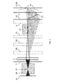
- Fig. 1 the pulsed laser beam (2) of a femto- or pikosen Humanlasers with approximately Gaussian intensity distribution over the laser beam cross section (IG) after its exit from the laser (1) by means of at least one beam expander (3) to a laser beam with approximately Gaussian intensity distribution but enlarged Cross-section (IGA) shaped.
- the laser beam passes through a beam homogenizer (4) and optionally an additional lens or a supplementary lens system (16) in the homogeneous spot at the location (P) on the optical axis (5) of the laser beam (beam axis) a homogeneous, top-flat intensity profile Generate designated intensity distribution (IAH) of the laser beam.
- IAH Generate designated intensity distribution
- a diaphragm (6) with a predetermined aperture geometry and a mask (7) with a predetermined mask opening geometry in place P.
- the undiffracted and diffracted beam portions of the laser beam pulses transmitted by the diaphragm (6) and the mask (7) positioned in the homogeneous spot at location (P) are detected by means of a field lens or a field lens system (8) and, after reflection, at least one 90 ° -Umlenkspiegel (9), a lens (10) in the image plane (11) shown.
- a detailed, with a predetermined mapping ratio (V (a O / a S ): 1), reduced image (14) of the generated by the diaphragm and the mask given structured intensity profile over the laser beam cross section.
- the variation of the distance (s) between the main plane (35) of the imaging objective (10) and the substrate surface (12) is preferably effected by means of the z-axis of the xyz coordinate stage (32) on which the substrate (13) is positioned.
- the variation of the distance (s) can also take place with the aid of the linear axes (33, 34), to which the field lens or the field lens system (8) and the objective (10) are fastened and thus along a predetermined path the optical axis (5) are displaceable, without changing the imaging properties of the optical system.
- a beam cross-section reducer must be used instead of the beam expander (3). This may be necessary, for example, in frequency doubling (SHG) or frequency tripling (THG) or frequency quadrupling (FHG) of the fundamental wavelength of the laser beam with the aid of the optional device (15); For example, in the frequency doubling of the CPA 2010 laser from Clark Inc. with 775 nm central fundamental wavelength, only about 40% and with frequency tripling are only 6-8% of the original pulse energy of the laser beam with the fundamental wavelength available.
- the usable mask surface would then be very small, but it would be sufficient, with a small Aperture or mask opening, ie with a very small imaging cross-section of, for example, 1 micron 2 and below on the substrate, very fine holes and precise structure edges and the layers structured material removal even very small three-dimensional microstructures (3d structures) to produce.
- a detailed, with a predetermined mapping ratio (V), reduced image (14) of the intensity profile generated by the diaphragm (6) and the mask (7) over the laser beam cross section and thus the generation of predetermined microstructures using the fs and ps mask projection method is only possible if the at the transmitting mask areas, eg at a grating mask, diffracted laser beam components to the imaging plane (11) and contribute to the image, otherwise a loss of information occurs and the transmission geometry of the mask and thus generated by the mask, predetermined structured intensity profile of the laser beam is imaged only inaccurately in the image plane. All optical components which are arranged according to the mask (7) must therefore have a sufficiently large aperture so that the diffracted laser beam components can also be imaged and contribute to the imaging. Simulation calculations and experiments have shown that the first to at least the third order of diffraction must also be mapped in order to obtain a detailed representation of the mask generated by the mask intensity profile of the laser radiation in the imaging plane (11).
- the high photon densities in the laser beam focusses of fs and ps laser beams lead to the formation of intense air plasmas or plasmas of the protective gas used in the beam path to protect the optical components against contamination in the focal areas of the beam guiding and shaping system (see also US Pat Fig. 2 and 3 ).
- the plasma ignited by the intermediate focus (17) in the beam path of the laser beam between the beam homogenizer (4) and the mask (7) reduces the homogeneity of the fluence distribution of the laser beam in the plane of the mask (7) and that by the focus 1 (19) in The focus distance f of the objective (10) or the plasma ignited by the focus 2 (22) between the field lens system (8) and the objective (10) leads to a reduction in the quality of the imaged mask opening geometry, eg to reduce the sharpness of edges Image plane (11), so that no homogeneous removal of material via the predetermined by the opening geometries of the mask (7) surface areas on the substrate (13).
- These plasmas thus influence the optical quality of the subsequent laser beam components, in particular at high pulse repetition frequencies (repetition rates) of the laser, and cause a reduction in the level of detail of the image and thus also of the microstructures produced.
- vacuum cuvettes (18, 20, 23) are inserted into the beam path in the region of the foci (17, 19, 22). These cuvettes surround the focus area, have two windows (25) coated with transmitting interference layer systems or a window (25) and a pinhole (26) for the almost lossless transmission of the laser radiation, are evacuated to at least pre-vacuum and must be included in the calculation of the total optical Systems are involved.
- the entire optical system starting at the output of the laser (1) to the imaging lens (10) can be positioned in a vacuum chamber.
- an auxiliary lens (16) a field lens system (8) consisting of two lenses, for example, and an objective (10) consisting of two lenses, for example, are used.
- a field lens system (8) consisting of two lenses, for example
- an objective (10) consisting of two lenses, for example
- the intermediate focus (17) of the beam path is located between the additional lens (16) and the diaphragm-mask combination (6, 7).
- the focus 1 (19) of the imaging optical system consisting of the field lens system (8) and the objective (10) is located between the objective (10) and substrate surface (12); the image plane (11) is located on the substrate surface (12).
- the painted area (2a) illustrates the propagation of the diffracted laser beam portions of the diffraction orders 1 to 5 of a fs laser beam having a central wavelength of 775 nm, for example, from the center of a bar grating mask (7) having a grating period of 200 ⁇ m for the generation of a Beam intensity profile according to (14) in Fig. 1 , but with an in Fig. 1 not shown higher number of radiation transmitting and diffracting columns, go out.
- the vacuum cuvette 1 (18) surrounds the intermediate focus (17) and the vacuum cuvette 2 (20) surrounds the focus 1 (19).
- the imaging plane (11) is located on the substrate surface (12).
- the dotted rectangles indicate further 90 ° deflection mirrors (29, 30, 31) which can be used to fold the beam path and increase the compactness of the entire beam guidance and shaping system (see Fig. 5 ). If a sufficiently long space is available, the entire optical system can also be realized without the deflecting mirrors (9, 29, 30, 31).
- FIG. 4a schematically illustrated vacuum cuvette 1 (18) consists of two interchangeable plane-parallel circular windows (25) made of a material transparent to the laser wavelength material and a hollow cylindrical spacer (27) having a flange (28) for connecting a vacuum pump.
- the windows are attached vacuum-tight to the spacer.
- the vacuum cuvette 1 (18) is positioned so that the laser beam focus (17) is at its center.
- the distance between the window inner surfaces parallel to the optical axis is at least 100 mm.
- FIG. 4b schematically illustrated vacuum cuvette 2 (20) has only one transmitting window (25) for the transmission of the laser radiation coming from the lens; the diameter of the transmitting window surface must be chosen so large that the propagation of the diffracted laser beam components (2a) (see Fig. 2 ) at least the diffraction orders 1 to 3 is possible without hindrance.
- a disc with a pinhole (26) for the transmission of the laser radiation is inserted, because the intensity of the laser radiation in this area can be above the damage threshold of the window material.
- the cross-section of the pinhole (26) is only slightly larger than the total laser beam cross-section at that location and is in the range of one to several tens of square microns, in particular for the intended applications in the fields of micro- and nanostructuring.
- the vacuum required to avoid a plasma in the region of the focus (19) is achieved with the aid of a vacuum pump with sufficiently high suction power.
- a cross-jet protective gas nozzle (21) is mounted between the vacuum cuvette (20) and the substrate (13) Transverse gas flow generated.
- the beam-guiding variant 1 is preferably suitable for the realization of the smallest imaging cross-sections for the generation of structures with detail dimensions in the micro and nano-meter range, since after the focus 1 no further optical Components are present whose aberrations errors (eg aberrations of lenses) can affect the detail accuracy of the image negative.
- an additional lens (16) a field lens system (8) consisting of two lenses and an objective (10) consisting of two lenses are also used.
- a field lens system (8) consisting of two lenses and an objective (10) consisting of two lenses are also used.
- the intermediate focus (17) of the beam path is again between the additional lens (16) and the diaphragm mask combination (6,7).
- the focus 2 (22) of the imaging optical system consisting of the field lens system (8) and the objective (10) is located between field lens system (8) and objective (10) in this beam guidance variant 2, so that in order to avoid a plasma in the region of focus 2 (22) the vacuum cuvette (23) can be used with two transmitting windows for the laser radiation (see Fig.
- the diameter of the transmitting window surfaces must be chosen so large that the propagation of the diffracted laser beam components (2a) (see Fig. 3 ) at least the diffraction orders 1 to 3 is possible without hindrance.
- the imaging plane (11) is located on the substrate surface (12).
- a shielding gas nozzle system (24) is provided which generates a gas flow between the objective (10) and the substrate (13).
- the dotted rectangles indicate further 90 ° deflection mirrors (29, 30, 31), which can be used to fold the beam path and increase the compactness of the entire beam guidance and shaping system (see Fig. 5 ).
- the entire optical system can also be realized without the deflecting mirrors (9, 29, 30, 31).
- the beam guidance variant 2 is preferably suitable for the realization of larger imaging cross sections in the range of more than a few 10 ⁇ m 2 to 1 mm 2 .
- FIG. 5 an fs-laser mask projection system for the realization of the beam guidance variant 2 is shown (see Fig. 3 ).
- the dimension arrows with the dimensions indicate the distances of the optical components in millimeters.
- Four 90 ° deflection mirrors (29, 30, 31, 9) are used to achieve a compact design of the system and its integration into a FS-150-10 fs laser microstructuring system of the company "3D-Mikromac AG ", which is designed for microstructuring by means of the fs laser focus method to enable.
- this system uses a Clark MXR CPA 2010 laser with the following parameters: central wavelength 775 nm, pulse duration 150 fs, pulse energy 1 mJ, pulse repetition frequency 1 kHz; Beam diameter at the laser output 3 mm, Gaussian intensity distribution over the laser beam cross section.
- the intensity profile of the laser beam pulse is thereby formed in the homogeneous spot at location P at which the mask (7) is positioned.
- microstructures with detail dimensions down to the submicron range can be created. These include, for example, optical diffraction gratings for the visible wavelength range with grating periods of 1 ⁇ m and below.
- the three-dimensional microstructures preferably produced by layer-wise structured removal, have a high edge sharpness, a high wall steepness, and low wall and floor roughnesses. Due to the low thermal and shock wave load of the adjacent, non-structured substrate areas, material modifications and pocketing at the structural edges are avoided to a great extent in the structuring of brittle materials.
- a multi-beam processing in the micro range e.g. parallel generation of trench-shaped and truncated-pyramidal structures or parallel structuring or separation of thin-film stacks.
Landscapes
- Physics & Mathematics (AREA)
- Optics & Photonics (AREA)
- Engineering & Computer Science (AREA)
- Plasma & Fusion (AREA)
- Mechanical Engineering (AREA)
- Laser Beam Processing (AREA)
- Lasers (AREA)
Priority Applications (7)
| Application Number | Priority Date | Filing Date | Title |
|---|---|---|---|
| EP14167931.6A EP2944413A1 (fr) | 2014-05-12 | 2014-05-12 | Dispositif de projection de masque de rayons laser femtosecondes et picosecondes avec une lâme, un masque et des systèmes de lentilles |
| RU2016147555A RU2689018C2 (ru) | 2014-05-12 | 2015-05-12 | Устройство для проецирования маски пучком фемтосекундного и пикосекундного лазера, содержащее ограничитель, маску и системы линз |
| CN201580027326.6A CN106457467B (zh) | 2014-05-12 | 2015-05-12 | 用于将飞秒或皮秒激光束掩模投射到衬底表面上的设备 |
| EP15731108.5A EP3142824B1 (fr) | 2014-05-12 | 2015-05-12 | Dispositif de projection de masque de rayons laser femtosecondes et picosecondes avec une lâme, un masque et des systèmes de lentilles |
| PCT/IB2015/053494 WO2015173735A1 (fr) | 2014-05-12 | 2015-05-12 | Dispositif pour projection de masque de faisceaux laser des femtosecondes et des picosecondes au moyen d'une lame, masque et systèmes de lentilles |
| US15/302,792 US10780525B2 (en) | 2014-05-12 | 2015-05-12 | Device for mask projection of femtosecond and picosecond laser beams with blade, mask, and lens system |
| BR112016024485-0A BR112016024485B1 (pt) | 2014-05-12 | 2015-05-12 | Dispositivo para projeção de máscara de feixes de laser de femtossegundos e picossegundos em uma superfície de substrato |
Applications Claiming Priority (1)
| Application Number | Priority Date | Filing Date | Title |
|---|---|---|---|
| EP14167931.6A EP2944413A1 (fr) | 2014-05-12 | 2014-05-12 | Dispositif de projection de masque de rayons laser femtosecondes et picosecondes avec une lâme, un masque et des systèmes de lentilles |
Publications (1)
| Publication Number | Publication Date |
|---|---|
| EP2944413A1 true EP2944413A1 (fr) | 2015-11-18 |
Family
ID=50687336
Family Applications (2)
| Application Number | Title | Priority Date | Filing Date |
|---|---|---|---|
| EP14167931.6A Withdrawn EP2944413A1 (fr) | 2014-05-12 | 2014-05-12 | Dispositif de projection de masque de rayons laser femtosecondes et picosecondes avec une lâme, un masque et des systèmes de lentilles |
| EP15731108.5A Active EP3142824B1 (fr) | 2014-05-12 | 2015-05-12 | Dispositif de projection de masque de rayons laser femtosecondes et picosecondes avec une lâme, un masque et des systèmes de lentilles |
Family Applications After (1)
| Application Number | Title | Priority Date | Filing Date |
|---|---|---|---|
| EP15731108.5A Active EP3142824B1 (fr) | 2014-05-12 | 2015-05-12 | Dispositif de projection de masque de rayons laser femtosecondes et picosecondes avec une lâme, un masque et des systèmes de lentilles |
Country Status (6)
| Country | Link |
|---|---|
| US (1) | US10780525B2 (fr) |
| EP (2) | EP2944413A1 (fr) |
| CN (1) | CN106457467B (fr) |
| BR (1) | BR112016024485B1 (fr) |
| RU (1) | RU2689018C2 (fr) |
| WO (1) | WO2015173735A1 (fr) |
Cited By (4)
| Publication number | Priority date | Publication date | Assignee | Title |
|---|---|---|---|---|
| CN106141427A (zh) * | 2015-04-27 | 2016-11-23 | 维嘉数控科技(苏州)有限公司 | 自动获取激光焦点的方法 |
| CN113296178A (zh) * | 2021-06-09 | 2021-08-24 | 中国工程物理研究院激光聚变研究中心 | 一种co2激光在熔石英表面直接制备正弦相位光栅的方法 |
| CN116851906A (zh) * | 2023-05-30 | 2023-10-10 | 深圳市单色科技有限公司 | 可灵活调控焦点形态结构的激光加工系统及方法 |
| DE102024000687B3 (de) | 2024-02-22 | 2025-05-15 | Hochschule Mittweida (FH), Körperschaft des öffentlichen Rechts | Einrichtung zur Mikrostrukturierung wenigstens eines Bereichs wenigstens einer Oberfläche eines Körpers mit Laserstrahlung wenigstens eines Lasers und Verwendung eines Mikrospiegelarrays im Strahlengang einer Laserstrahlung nach wenigstens einem Laser |
Families Citing this family (26)
| Publication number | Priority date | Publication date | Assignee | Title |
|---|---|---|---|---|
| EP2944413A1 (fr) | 2014-05-12 | 2015-11-18 | Boegli-Gravures S.A. | Dispositif de projection de masque de rayons laser femtosecondes et picosecondes avec une lâme, un masque et des systèmes de lentilles |
| EP3037253A1 (fr) | 2014-12-22 | 2016-06-29 | Boegli-Gravures S.A. | Micro-gaufrage |
| DE102015211999A1 (de) * | 2015-06-29 | 2016-12-29 | Trumpf Werkzeugmaschinen Gmbh + Co. Kg | Laserbearbeitungskopf und Laserbearbeitungsmaschine damit |
| EP3184292A1 (fr) | 2015-12-22 | 2017-06-28 | Boegli-Gravures S.A. | Dispositif de gaufrage de matériau d'emballage à l'aide d'un jeu de rouleaux de gaufrage du type male-femelle |
| EP3251825A1 (fr) | 2016-05-31 | 2017-12-06 | Boegli-Gravures S.A. | Procédé et dispositif de gaufrage de matériau plan |
| EP3300612A1 (fr) | 2016-10-03 | 2018-04-04 | Boegli-Gravures S.A. | Joint de papier sans discontinuité pour emballages papier en forme de tube fermés au moyen de papier gaufré et joint de revêtement intérieur refermable au moyen de revêtement structuré |
| EP3339012A1 (fr) | 2016-12-20 | 2018-06-27 | Boegli-Gravures S.A. | Procédé et structure de gaufrage pour maximiser l'accumulation de pression au niveau du gaufrage tournant de feuilles |
| DE102017206461B4 (de) * | 2017-04-13 | 2019-05-02 | Schott Ag | Vorrichtung und Verfahren zum laserbasierten Trennen eines transparenten, sprödbrechenden Werkstücks |
| EP3415306A1 (fr) | 2017-06-14 | 2018-12-19 | Boegli-Gravures S.A. | Procédé et structure de gaufrage par pression à haute densité pour créer des zones hautement réfléchissante incurvées ou ombrées sur des feuilles gaufrées en rotation |
| EP3437849A1 (fr) | 2017-08-03 | 2019-02-06 | Boegli-Gravures SA | Outil et procédé de gaufrage d'un matériau d'emballage comportant un motif de gaufrage ayant un code à faible visibilité |
| EP3814129B1 (fr) | 2018-06-26 | 2025-03-26 | Boegli-Gravures S.A. | Procédé et dispositif de gaufrage de structures en relief |
| US12304001B2 (en) * | 2019-04-02 | 2025-05-20 | Asmpt Singapore Pte. Ltd. | Optimised laser cutting |
| CA3133730A1 (fr) * | 2019-04-16 | 2020-10-22 | Ismael GUILLOTTE | Procede de realisation d'un effet visuel d'irisation sur la surface d'un materiau, dispositifs pour sa mise en oeuvre et piece ainsi obtenue |
| JP7353171B2 (ja) * | 2019-12-26 | 2023-09-29 | 株式会社ディスコ | レーザー加工装置 |
| EP3851272A1 (fr) | 2020-01-17 | 2021-07-21 | Boegli-Gravures S.A. | Système de gaufrage doté d'une cassette de gaufrage |
| EP3964356A1 (fr) | 2020-09-03 | 2022-03-09 | Boegli-Gravures SA | Procédé et système de fabrication d'un dispositif de gaufrage à l'aide d'un masque de gravure |
| EP3964355A1 (fr) | 2020-09-03 | 2022-03-09 | Boegli-Gravures S.A. | Procédé et système de fabrication d'un dispositif de gaufrage |
| CN112222609A (zh) * | 2020-09-22 | 2021-01-15 | 中国科学院上海光学精密机械研究所 | 高峰值功率激光焦点的定位方法 |
| DE102020130651B3 (de) * | 2020-11-19 | 2022-05-05 | Trumpf Laser- Und Systemtechnik Gmbh | Vorrichtung zum Erzeugen einer definierten Laserbeleuchtung auf einer Arbeitsebene |
| CN113267120B (zh) * | 2021-04-30 | 2024-11-22 | 长春理工大学 | 不均匀光束空间相干长度测量装置及方法 |
| MX2024001945A (es) | 2021-08-13 | 2024-03-01 | Boegli Gravures Sa | Metodo y herramienta para gofrar papel barrera. |
| EP4177057A1 (fr) * | 2021-11-05 | 2023-05-10 | Boegli-Gravures S.A. | Procédé de gravure de motifs de code sur la surface de la pièce solide d'outil |
| CN114406450B (zh) * | 2022-01-25 | 2023-11-07 | 中国工程物理研究院激光聚变研究中心 | 一种激光加工中高均匀紧聚焦长光针的调控装置与方法 |
| CN114523192A (zh) * | 2022-02-16 | 2022-05-24 | 浙江大学 | 飞秒激光加工系统和三维表面形貌及温度在线测量方法 |
| EP4368036A1 (fr) | 2022-11-11 | 2024-05-15 | Boegli-Gravures S.A. | Procédé et outil pour gaufrer du papier biodégradable pour fabriquer des filtres de cigarette |
| CN121179018B (zh) * | 2025-10-31 | 2026-04-17 | 中南大学 | 一种异质材料的飞秒皮秒复合激光焊接方法及装备 |
Citations (6)
| Publication number | Priority date | Publication date | Assignee | Title |
|---|---|---|---|---|
| US20030127441A1 (en) * | 2002-01-07 | 2003-07-10 | Haight Richard A. | Debris minimization and improved spatial resolution in pulsed laser ablation of materials |
| JP2003211278A (ja) * | 2002-01-22 | 2003-07-29 | Sumitomo Heavy Ind Ltd | レーザ加工装置 |
| US20050059265A1 (en) * | 2003-09-16 | 2005-03-17 | The Trustees Of Columbia University In The City Of New York | Systems and methods for processing thin films |
| WO2010111798A1 (fr) | 2009-03-30 | 2010-10-07 | Boegli-Gravures S.A. | Procédé et dispositif de structuration d'une surface de corps solide par revêtement dur au moyen d'un premier laser à durée d'impulsion de l'ordre de la nanoseconde et d'un second laser à durée d'impulsion de l'ordre de la picoseconde ou de la femtoseconde |
| EP2336823A1 (fr) | 2009-12-18 | 2011-06-22 | Boegli-Gravures S.A. | Procédé et dispositif de fabrication de masques pour une installation laser de production de microstructures |
| US20120243094A1 (en) * | 2009-12-18 | 2012-09-27 | Boegli-Gravures S.A. | Method and device for producing color pattern by means of diffraction gratings |
Family Cites Families (67)
| Publication number | Priority date | Publication date | Assignee | Title |
|---|---|---|---|---|
| EP0139066B1 (fr) | 1983-10-21 | 1988-03-30 | Boegli-Gravures | Dispositif pour satiner une feuille |
| SU1508468A1 (ru) | 1988-01-14 | 1995-01-20 | Ю.В. Лакиза | Устройство для лазерной обработки |
| US5359176A (en) * | 1993-04-02 | 1994-10-25 | International Business Machines Corporation | Optics and environmental protection device for laser processing applications |
| CH688205A5 (de) | 1994-06-06 | 1997-06-13 | Boegli Gravures Sa | Vorrichtung zur Behandlung von Flachmaterial. |
| GB9514558D0 (en) * | 1995-07-17 | 1995-09-13 | Gersan Ets | Marking diamond |
| DE59800229D1 (de) | 1997-12-19 | 2000-09-14 | Boegli Gravures Sa | Vorrichtung zum Satinieren einer Folie, Anwendung dieser Vorrichtung und Verfahren zum Betrieb der Vorrichtung |
| SE9800665D0 (sv) * | 1998-03-02 | 1998-03-02 | Micronic Laser Systems Ab | Improved method for projection printing using a micromirror SLM |
| US6333485B1 (en) * | 1998-12-11 | 2001-12-25 | International Business Machines Corporation | Method for minimizing sample damage during the ablation of material using a focused ultrashort pulsed beam |
| US6262390B1 (en) * | 1998-12-14 | 2001-07-17 | International Business Machines Corporation | Repair process for aluminum nitride substrates |
| US6359257B1 (en) * | 1999-02-19 | 2002-03-19 | Lsp Technologies, Inc. | Beam path clearing for laser peening |
| EP1048369A1 (fr) | 1999-03-22 | 2000-11-02 | Boegli-Gravures S.A. | Dispositif de gaufrage pour matériel plat et étendu |
| AU772613B2 (en) | 1999-05-06 | 2004-05-06 | Boegli-Gravures S.A. | Device for embossing a foil, application of the device, method for its manufacture, and method for the operation of the device |
| CN1273905A (zh) | 1999-05-17 | 2000-11-22 | 伯格利-格拉维瑞斯股份有限公司 | 处理扁平材料的设备 |
| CN1277133A (zh) * | 1999-06-10 | 2000-12-20 | 吴建良 | 一种高效防伪掩模式激光打标装置 |
| CN2382502Y (zh) * | 1999-06-10 | 2000-06-14 | 吴建良 | 一种高效防伪掩模式激光打标装置 |
| JP2001321979A (ja) * | 2000-05-12 | 2001-11-20 | Matsushita Electric Ind Co Ltd | レーザー穴加工機の加工粉集塵装置 |
| US6665998B1 (en) | 2000-05-17 | 2003-12-23 | Boegli-Gravures Sa | Embossing device for planar materials |
| US6715411B1 (en) | 2000-05-17 | 2004-04-06 | Boegli Gravures S.A. | Device for the treatment of flat materials |
| JP3479833B2 (ja) * | 2000-08-22 | 2003-12-15 | 日本電気株式会社 | レーザ修正方法および装置 |
| US6580053B1 (en) * | 2000-08-31 | 2003-06-17 | Sharp Laboratories Of America, Inc. | Apparatus to control the amount of oxygen incorporated into polycrystalline silicon film during excimer laser processing of silicon films |
| ATE330785T1 (de) | 2000-10-13 | 2006-07-15 | Boegli Gravures Sa | Vorrichtung zum prägen und satinieren von flachmaterial |
| WO2002076716A1 (fr) | 2001-03-26 | 2002-10-03 | Boegli-Gravures S.A. | Dispositif de traitement de materiaux plats |
| DE10123097B8 (de) * | 2001-05-07 | 2006-05-04 | Jenoptik Automatisierungstechnik Gmbh | Werkzeugkopf zur Lasermaterialbearbeitung |
| US6635844B2 (en) * | 2002-01-03 | 2003-10-21 | United Microelectronics Corp. | Apparatus for on-line cleaning a wafer chuck with laser |
| JP4459514B2 (ja) * | 2002-09-05 | 2010-04-28 | 株式会社半導体エネルギー研究所 | レーザーマーキング装置 |
| TW200414280A (en) * | 2002-09-25 | 2004-08-01 | Adv Lcd Tech Dev Ct Co Ltd | Semiconductor device, annealing method, annealing apparatus and display apparatus |
| EP1437213A1 (fr) | 2002-12-23 | 2004-07-14 | Boegli-Gravures S.A. | Dispositif pour satiner et pour gauffrer un matériau plat |
| NL1022860C2 (nl) * | 2003-03-06 | 2004-09-07 | Concepto Worldwide Ltd | Inrichting voor het stimuleren van het vrouwelijk geslachtsorgaan, verpakking en doseerorgaan. |
| JP4205486B2 (ja) * | 2003-05-16 | 2009-01-07 | 株式会社ディスコ | レーザ加工装置 |
| GB2414954B (en) * | 2004-06-11 | 2008-02-06 | Exitech Ltd | Process and apparatus for ablation |
| EP1609587B1 (fr) | 2004-06-22 | 2008-12-03 | Boegli-Gravures S.A. | Dispositif pour glacer et gaufrer des matériaux plats |
| US7744770B2 (en) * | 2004-06-23 | 2010-06-29 | Sony Corporation | Device transfer method |
| WO2007012215A1 (fr) | 2005-07-28 | 2007-02-01 | Boegli-Gravures Sa | Procede et dispositif de structuration ciblee d'une surface a l'aide d'un systeme laser |
| DE102006007750A1 (de) | 2006-02-20 | 2007-08-23 | Wavelight Ag | Verfahren und optische Anordnung zur Kontrolle der Fokustiefe eines abbildenden optischen Systems |
| KR100795526B1 (ko) | 2006-03-02 | 2008-01-16 | 한국표준과학연구원 | 물질상태변이 유발을 통한 레이저 가공방법 및 가공장치 |
| EP1867470B1 (fr) | 2006-06-15 | 2009-06-17 | Boegli-Gravures S.A. | Procédé et dispositif pour l'authentification de marques d'identification sur une feuille d'emballage ou un emballage |
| JP4404085B2 (ja) * | 2006-11-02 | 2010-01-27 | ソニー株式会社 | レーザ加工装置、レーザ加工ヘッド及びレーザ加工方法 |
| ES2391648T3 (es) | 2006-11-22 | 2012-11-28 | Boegli-Gravures S.A. | Dispositivo para el satinado y gofrado de láminas de empaque |
| RU2009139989A (ru) | 2007-05-04 | 2013-11-10 | Боэгли-Гравюр С.А. | Способ и устройство для распознавания идентификационной метки на огибающей поверхности объекта |
| EP2027993A1 (fr) | 2007-08-23 | 2009-02-25 | Boegli-Gravures S.A. | Dispositif de préparation de papier d'emballage au prochain processus d'emballage |
| US8274735B2 (en) * | 2007-09-14 | 2012-09-25 | Fry Robert C | Analytical laser ablation of solid samples for ICP, ICP-MS, and FAG-MS analysis |
| WO2009155720A1 (fr) | 2008-06-26 | 2009-12-30 | Boegli-Gravures S.A. | Dispositif de satinage et de gaufrage de feuilles d’emballage |
| BRPI1012733A2 (pt) | 2009-03-30 | 2016-04-05 | Boegli Gravures Sa | método e dispositivo para a estruturação da superfície de um corpo sólido revestido com material duro por meio de um laser |
| EP2353858A1 (fr) | 2010-02-09 | 2011-08-10 | Boegli-Gravures S.A. | Dispositif de gaufrage de feuilles d'enveloppement |
| US8993919B2 (en) * | 2010-04-20 | 2015-03-31 | Panasonic Intellectual Property Management Co., Ltd. | Laser source and laser beam machine |
| EP2399732A1 (fr) | 2010-06-22 | 2011-12-28 | Boegli-Gravures S.A. | Dispositif de gaufrage de feuilles |
| EP2468493A1 (fr) | 2010-12-23 | 2012-06-27 | Boegli-Gravures S.A. | Dispositif de gaufrage de feuilles |
| US8582612B2 (en) * | 2011-01-27 | 2013-11-12 | Applied Energetics, Inc. | Optical amplifier for microwave bursts |
| EP2511088A1 (fr) | 2011-04-12 | 2012-10-17 | Boegli-Gravures S.A. | Procédé et dispositif pour la fabrication d'un emballage pour produits destinés à être fumés |
| EP2572820A1 (fr) | 2011-09-23 | 2013-03-27 | Boegli-Gravures S.A. | Procédé et dispositif de production d'une surface structurée sur un rouleau de gaufrage en acier |
| US10183318B2 (en) | 2011-09-23 | 2019-01-22 | Boegli-Gravures S.A. | Method and device for producing a structured surface on a steel embossing roller |
| SG11201405930WA (en) | 2012-04-17 | 2014-11-27 | Boegli Gravures Sa | Method for manufacturing a set of embossing rollers |
| EP2653301A1 (fr) | 2012-04-17 | 2013-10-23 | Boegli-Gravures S.A. | Procédé de fabrication d'un ensemble de rouleau de gaufrage |
| EP2671714A1 (fr) | 2012-06-08 | 2013-12-11 | Boegli-Gravures S.A. | Dispositif de gaufrage et/ou de perforation de feuilles pour marchandises issues du tabac |
| EP2711666A1 (fr) | 2012-09-20 | 2014-03-26 | Boegli-Gravures S.A. | Procédé de fabrication d'un ensemble de rouleaux de gaufrage coopérants entre eux et dipositif modèle pour l'exécution du procédé |
| EP2842730A1 (fr) | 2013-08-28 | 2015-03-04 | Boegli-Gravures S.A. | Dispositif pour le gaufrage de matériau d'emballage à l'aide d'un jeu de rouleaux de gaufrage du type mâle-femelle |
| EP2944413A1 (fr) | 2014-05-12 | 2015-11-18 | Boegli-Gravures S.A. | Dispositif de projection de masque de rayons laser femtosecondes et picosecondes avec une lâme, un masque et des systèmes de lentilles |
| WO2015185152A1 (fr) * | 2014-06-06 | 2015-12-10 | Trumpf Lasersystems For Semiconductor Manufacturing Gmbh | Dispositif et procédé de surveillance d'un faisceau laser |
| US20160074968A1 (en) * | 2014-09-11 | 2016-03-17 | Suss Microtec Photonic Systems Inc. | Laser etching system including mask reticle for multi-depth etching |
| CH708200A8 (de) | 2014-09-12 | 2015-03-13 | Boegli Gravures Sa | Verfahren und Vorrichtung zur Authentifizierung von Identifikations-Merkmalen auf einer Verpackungsfolie. |
| EP3037253A1 (fr) | 2014-12-22 | 2016-06-29 | Boegli-Gravures S.A. | Micro-gaufrage |
| EP3127435A1 (fr) | 2015-07-23 | 2017-02-08 | Boegli-Gravures S.A. | Procédé et dispositif permettant d'appliquer des caractéristiques d'identification à un feuillard d'emballage afin d'authentifier le garnissage traité |
| EP3184292A1 (fr) | 2015-12-22 | 2017-06-28 | Boegli-Gravures S.A. | Dispositif de gaufrage de matériau d'emballage à l'aide d'un jeu de rouleaux de gaufrage du type male-femelle |
| EP3251825A1 (fr) | 2016-05-31 | 2017-12-06 | Boegli-Gravures S.A. | Procédé et dispositif de gaufrage de matériau plan |
| EP3300612A1 (fr) | 2016-10-03 | 2018-04-04 | Boegli-Gravures S.A. | Joint de papier sans discontinuité pour emballages papier en forme de tube fermés au moyen de papier gaufré et joint de revêtement intérieur refermable au moyen de revêtement structuré |
| EP3415306A1 (fr) | 2017-06-14 | 2018-12-19 | Boegli-Gravures S.A. | Procédé et structure de gaufrage par pression à haute densité pour créer des zones hautement réfléchissante incurvées ou ombrées sur des feuilles gaufrées en rotation |
| DE202017105458U1 (de) | 2017-08-03 | 2017-10-27 | Boegli-Gravures S.A. | Vorrichtung und System zur Prägung von Verpackungsmaterial mit einem Prägemuster, das einen Code mit geringer Sichtbarkeit aufweist |
-
2014
- 2014-05-12 EP EP14167931.6A patent/EP2944413A1/fr not_active Withdrawn
-
2015
- 2015-05-12 BR BR112016024485-0A patent/BR112016024485B1/pt not_active IP Right Cessation
- 2015-05-12 EP EP15731108.5A patent/EP3142824B1/fr active Active
- 2015-05-12 RU RU2016147555A patent/RU2689018C2/ru active
- 2015-05-12 CN CN201580027326.6A patent/CN106457467B/zh not_active Expired - Fee Related
- 2015-05-12 WO PCT/IB2015/053494 patent/WO2015173735A1/fr not_active Ceased
- 2015-05-12 US US15/302,792 patent/US10780525B2/en not_active Expired - Fee Related
Patent Citations (6)
| Publication number | Priority date | Publication date | Assignee | Title |
|---|---|---|---|---|
| US20030127441A1 (en) * | 2002-01-07 | 2003-07-10 | Haight Richard A. | Debris minimization and improved spatial resolution in pulsed laser ablation of materials |
| JP2003211278A (ja) * | 2002-01-22 | 2003-07-29 | Sumitomo Heavy Ind Ltd | レーザ加工装置 |
| US20050059265A1 (en) * | 2003-09-16 | 2005-03-17 | The Trustees Of Columbia University In The City Of New York | Systems and methods for processing thin films |
| WO2010111798A1 (fr) | 2009-03-30 | 2010-10-07 | Boegli-Gravures S.A. | Procédé et dispositif de structuration d'une surface de corps solide par revêtement dur au moyen d'un premier laser à durée d'impulsion de l'ordre de la nanoseconde et d'un second laser à durée d'impulsion de l'ordre de la picoseconde ou de la femtoseconde |
| EP2336823A1 (fr) | 2009-12-18 | 2011-06-22 | Boegli-Gravures S.A. | Procédé et dispositif de fabrication de masques pour une installation laser de production de microstructures |
| US20120243094A1 (en) * | 2009-12-18 | 2012-09-27 | Boegli-Gravures S.A. | Method and device for producing color pattern by means of diffraction gratings |
Non-Patent Citations (4)
| Title |
|---|
| "Excimer laser technology", 2001 |
| A. LASKIN; V. LASKIN: "nshaper - Refractive Beam Shaping Optics for Advanced Laser Technologies", JOURNAL OF PHYSICS: CONFERENCE SERIES, vol. 276, 2011, pages 012171 |
| J. HERNANDEZ-RUEDAL, J. SIEGEL; D. PUERTO2; M. GALVAN-SOSA; W. GAWELDA3; J. SOLIS: "Ad-hoc design of temporally shaped fs laser pulses based on plasma dynamics for deep ablation in fused silica", APPL.PHYS. A, 2013, pages 112 |
| WEISSMANTEL, S.; REISSE, G.; HAEHNEL, F.; BERTRAM, R.; BOETTCHER, R.: "Production of microstructures in wide-band-gap and organic materials using pulsed laser ablation at 157 nm wavelength", APPLIED PHYSICS A, vol. 101, 2010, pages 491, XP019844854 |
Cited By (5)
| Publication number | Priority date | Publication date | Assignee | Title |
|---|---|---|---|---|
| CN106141427A (zh) * | 2015-04-27 | 2016-11-23 | 维嘉数控科技(苏州)有限公司 | 自动获取激光焦点的方法 |
| CN106141427B (zh) * | 2015-04-27 | 2018-05-18 | 维嘉数控科技(苏州)有限公司 | 自动获取激光焦点的方法 |
| CN113296178A (zh) * | 2021-06-09 | 2021-08-24 | 中国工程物理研究院激光聚变研究中心 | 一种co2激光在熔石英表面直接制备正弦相位光栅的方法 |
| CN116851906A (zh) * | 2023-05-30 | 2023-10-10 | 深圳市单色科技有限公司 | 可灵活调控焦点形态结构的激光加工系统及方法 |
| DE102024000687B3 (de) | 2024-02-22 | 2025-05-15 | Hochschule Mittweida (FH), Körperschaft des öffentlichen Rechts | Einrichtung zur Mikrostrukturierung wenigstens eines Bereichs wenigstens einer Oberfläche eines Körpers mit Laserstrahlung wenigstens eines Lasers und Verwendung eines Mikrospiegelarrays im Strahlengang einer Laserstrahlung nach wenigstens einem Laser |
Also Published As
| Publication number | Publication date |
|---|---|
| EP3142824B1 (fr) | 2018-08-29 |
| RU2016147555A (ru) | 2018-06-14 |
| CN106457467A (zh) | 2017-02-22 |
| WO2015173735A1 (fr) | 2015-11-19 |
| US20170066079A1 (en) | 2017-03-09 |
| BR112016024485A2 (pt) | 2017-08-15 |
| CN106457467B (zh) | 2019-04-16 |
| US10780525B2 (en) | 2020-09-22 |
| RU2016147555A3 (fr) | 2018-11-01 |
| EP3142824A1 (fr) | 2017-03-22 |
| RU2689018C2 (ru) | 2019-05-23 |
| BR112016024485B1 (pt) | 2022-07-12 |
Similar Documents
| Publication | Publication Date | Title |
|---|---|---|
| EP2944413A1 (fr) | Dispositif de projection de masque de rayons laser femtosecondes et picosecondes avec une lâme, un masque et des systèmes de lentilles | |
| EP2964416A2 (fr) | Procédé et dispositif de séparation d'un substrat | |
| WO2016079275A1 (fr) | Système de formage par faisceau optique asymétrique | |
| EP2964417A2 (fr) | Procédé et dispositif permettant de pratiquer des perforations dans un substrat et substrat produit avec ledit procédé et ledit dispositif | |
| EP1871566B1 (fr) | Procede de polissage fin/structuration de matieres dielectriques thermosensibles au moyen d'un rayonnement laser | |
| WO2016008768A1 (fr) | Procédé et dispositif d'usinage au laser de substrats plats cristallins, notamment de substrats semiconducteurs | |
| EP3624984B1 (fr) | Dispositif et procédé pour diviser une pièce le long d'une ligne d'usinage prédéfinie en utilisant un faisceau laser pulsé polychromatique et un filtre | |
| DE102020102077B4 (de) | Laserbearbeitungsvorrichtung und Verfahren zur Laserbearbeitung eines Werkstücks | |
| DE102021214310A1 (de) | Verfahren und Vorrichtung zum Erzeugen mindestens einer Hohlstruktur, EUVSpiegel und EUV-Lithographiesystem | |
| WO2021028534A1 (fr) | Procédé pour usiner une pièce | |
| DE10029110B4 (de) | Verfahren für die Materialbearbeitung und Verwendung desselben | |
| DE102020107760A1 (de) | Laserbearbeitungsvorrichtung und Verfahren zur Laserbearbeitung eines Werkstücks | |
| EP4034329A1 (fr) | Procédé pour produire des microstructures sur un cristal optique | |
| WO2022122251A1 (fr) | Usinage au laser d'un matériau à l'aide d'un élément filtrant à gradient | |
| DE102018120011A1 (de) | Schweißverfahren zum Verbinden eines transparenten, aluminiumoxidhaltigen ersten Substrats mit einem opaken zweiten Substrat | |
| WO2021151925A1 (fr) | Dispositif d'usinage au laser et procédé d'usinage au laser d'une pièce | |
| DE102005007792B4 (de) | Verfahren und Einrichtung zum Auftragsschweissen von Schichten aus Partikeln mit einer Korngrösse kleiner 20 μm auf Substrate | |
| DE102020127116B4 (de) | Vorrichtung und Verfahren zum Laserbearbeiten eines Werkstücks | |
| DE102021109579B4 (de) | Verfahren und vorrichtung zum ausbilden von modifikationen mit einem laserstrahl in einem material mit einer gekrümmten oberfläche | |
| DE10140533A1 (de) | Verfahren und Vorrichtung zur Mikrobearbeitung eines Werkstücks mit Laserstrahlung | |
| DE102007020704B4 (de) | Einrichtung für die Bearbeitung eines Werkstückes mit einem Laserstrahl | |
| DE4202941A1 (de) | Verfahren und vorrichtung zum materialabtrag an einem bewegten werkstueck | |
| DE69503693T2 (de) | Verfahren zur Bearbeitung von oxidischen Materialien mittels eines Laserstrahls | |
| EP4079443A1 (fr) | Procédé de vérification d'une distribution d'énergie appliquée au moyen d'un foyer linéaire d'un faisceau laser à l'intérieure d'un substrat et substrat | |
| WO2022008650A1 (fr) | Procédé et dispositif pour former des motifs sur une couche de structure par rayonnement laser |
Legal Events
| Date | Code | Title | Description |
|---|---|---|---|
| PUAI | Public reference made under article 153(3) epc to a published international application that has entered the european phase |
Free format text: ORIGINAL CODE: 0009012 |
|
| AK | Designated contracting states |
Kind code of ref document: A1 Designated state(s): AL AT BE BG CH CY CZ DE DK EE ES FI FR GB GR HR HU IE IS IT LI LT LU LV MC MK MT NL NO PL PT RO RS SE SI SK SM TR |
|
| AX | Request for extension of the european patent |
Extension state: BA ME |
|
| STAA | Information on the status of an ep patent application or granted ep patent |
Free format text: STATUS: THE APPLICATION IS DEEMED TO BE WITHDRAWN |
|
| 18D | Application deemed to be withdrawn |
Effective date: 20160519 |