EP2944436B1 - Structure de support doté d'éléments porteurs pouvant être verrouillés sans cliquetis - Google Patents
Structure de support doté d'éléments porteurs pouvant être verrouillés sans cliquetis Download PDFInfo
- Publication number
- EP2944436B1 EP2944436B1 EP15166717.7A EP15166717A EP2944436B1 EP 2944436 B1 EP2944436 B1 EP 2944436B1 EP 15166717 A EP15166717 A EP 15166717A EP 2944436 B1 EP2944436 B1 EP 2944436B1
- Authority
- EP
- European Patent Office
- Prior art keywords
- support
- clamping
- support element
- support frame
- locking
- Prior art date
- Legal status (The legal status is an assumption and is not a legal conclusion. Google has not performed a legal analysis and makes no representation as to the accuracy of the status listed.)
- Active
Links
Images


Classifications
-
- B—PERFORMING OPERATIONS; TRANSPORTING
- B25—HAND TOOLS; PORTABLE POWER-DRIVEN TOOLS; MANIPULATORS
- B25H—WORKSHOP EQUIPMENT, e.g. FOR MARKING-OUT WORK; STORAGE MEANS FOR WORKSHOPS
- B25H1/00—Work benches; Portable stands or supports for positioning portable tools or work to be operated on thereby
- B25H1/02—Work benches; Portable stands or supports for positioning portable tools or work to be operated on thereby of table type
- B25H1/04—Work benches; Portable stands or supports for positioning portable tools or work to be operated on thereby of table type portable
-
- B—PERFORMING OPERATIONS; TRANSPORTING
- B25—HAND TOOLS; PORTABLE POWER-DRIVEN TOOLS; MANIPULATORS
- B25H—WORKSHOP EQUIPMENT, e.g. FOR MARKING-OUT WORK; STORAGE MEANS FOR WORKSHOPS
- B25H1/00—Work benches; Portable stands or supports for positioning portable tools or work to be operated on thereby
- B25H1/14—Work benches; Portable stands or supports for positioning portable tools or work to be operated on thereby with provision for adjusting the bench top
- B25H1/16—Work benches; Portable stands or supports for positioning portable tools or work to be operated on thereby with provision for adjusting the bench top in height
-
- B—PERFORMING OPERATIONS; TRANSPORTING
- B25—HAND TOOLS; PORTABLE POWER-DRIVEN TOOLS; MANIPULATORS
- B25H—WORKSHOP EQUIPMENT, e.g. FOR MARKING-OUT WORK; STORAGE MEANS FOR WORKSHOPS
- B25H1/00—Work benches; Portable stands or supports for positioning portable tools or work to be operated on thereby
- B25H1/14—Work benches; Portable stands or supports for positioning portable tools or work to be operated on thereby with provision for adjusting the bench top
- B25H1/18—Work benches; Portable stands or supports for positioning portable tools or work to be operated on thereby with provision for adjusting the bench top in inclination
Definitions
- the invention relates to a support frame, in particular workbench or workpiece support with a first support member, a pivotally hinged thereto second support member and the two support elements associated retaining elements which fix the two support members in a locking position in a first pivot position and in a release position, a pivoting of the support elements in allow a second pivot position.
- a support frame with two support elements, one of which extends in a use position substantially in the horizontal direction and a second support member extends substantially in the vertical direction describes the WO 00/53375 A1 .
- a jaw assembly At the upwardly facing end of the substantially vertically extending support member sits a jaw assembly.
- the two support elements are held by means of holding means in a position of use, which corresponds to a first pivot position of the two support members to each other. If the retaining means are brought from a locking position into a release position, then the support elements can be pivoted into a non-use position.
- Workbenches, workpiece supports have two mutually pivotable support members which are fixed in a position of use by means of holding means in a first pivot position also show the US 2005/0011421 A1 .
- CH 347966 and DE 197 35 336 A1 show the US 2005/0011421 A1 .
- the invention has for its object to further develop the generic support frame nutzsvorteilhaft.
- the holding means have a clamping element.
- the clamping element can be brought from a locking position into a release position.
- the clamping element is in the position of use of the support frame to a clamping edge by clamping.
- the clamping element may be associated with the first support element.
- the clamping flank can be assigned to the second support element.
- the clamping element may be formed by a pivotable clamping lever.
- the clamping element can be movably arranged in a cavity of the support element.
- the support element may be a pipe, in particular a square pipe. In the cavity of the tube, the clamping element may be located. It can be arranged pivotably about a pivot axis in the pipe.
- the pipe wall may have a window, which may have a slot shape.
- a head of the clamping element protrudes to the outside.
- the clamping edge which is formed in particular by a peripheral edge of a flange plate which is fixedly connected to the second support member.
- This clamping edge extends at an acute angle to the pivot plane of the clamping element, wherein the angle is less than the maximum self-locking angle, so that the clamping element rests in the clamping position while exerting a torque about the pivot axis of the two support elements on the clamping edge.
- a portion of the head of the clamping element is supported on the clamping edge and a portion of the head of the clamping element opposite this section at an edge of the Slit through which the clamping element protrudes from the cavity of the support element to the outside.
- the clamping element is displaceable by a displacement of an actuating member of the locking position corresponding to the clamping position in the release position.
- the actuator may have a window and be displaceable within the tube cavity of the support element.
- the lever arm of the clamping element passes through the window of the actuator.
- the latter has a pressure flank and a lifting flank.
- the actuator may be loaded by a spring, in particular a tension spring in the direction of the clamping position. The pressure edge of the window acts on the clamping element in the direction of its clamping position.
- the actuating member If the actuating member is displaced against the restoring force of the spring, the lifting flank lying opposite the pressure flank, after passing through a movement play, engages on the lever arm of the clamping element in order to bring the clamping element into the release position.
- the head of the clamping element which in particular has an oblique face, in the opening plane of the window of the support element, in front of which displaces a broad side surface of the flange during pivoting of the two support elements, on which the end face of the clamping element can be supported, if the actuator due to the force of the spring acting on it shifted back again, so that the pressure edge acts on the clamping element.
- the holding elements on fixed stops may have a stop, in particular a pin-shaped stop, which is associated with the first support element. In the position of use can abut against this stop a counter-stop of the other support element.
- the counter-stop is formed by a stop table of the flange plate.
- the fixed stops can absorb the clamping force in the clamping position, which transmits the clamping element on the clamping edge.
- a locking pin provided, which rests in the locking position in a latching niche.
- the latching pin may be assigned to the first support element and the latching niche to the second support element, in particular the flange plate.
- the locking pin can be firmly seated on the actuating member, so that it can be brought together with the clamping element in a displacement of the actuating member of the locking position in a release position.
- the locking pin can slide on pivoting of the two support elements on a guide flank of a guide slot along.
- the guide flank extends on a circular arc line about the pivot axis about which the two support elements are pivotable.
- the axis about which the two support elements are pivotable extends transversely to the plane of extent of the flange plate. It extends transversely to the surface extension of two mutually parallel walls of the tubular support element.
- the pivot axis about which the clamping element is pivotable runs parallel to the surface plane of extension of these two tube walls.
- the pivoting plane of the clamping element extends in particular transversely to the surface extension of two transverse to the first tube walls second tube walls of a rectangular cross-section having tube, which forms the first support member.
- the second support element extends in the position of use approximately in a horizontal plane.
- the first support member has at its lower end a first foot. Adjacent to the lower end, the second support element is articulated on the first support element. The free end of the second support element forms a second foot.
- There are two pairs of legs are provided, each having a first support member and a second support member, so that the support frame has a total of four feet.
- the two support element pairs are connected to each other via connecting elements.
- the connecting elements may be rigid traverses, each rigidly interconnecting two first support elements and two second support elements.
- first support member may be a support element.
- the further support element can be assigned to be telescopically associated with the first support element.
- a carrier attached to the end of the further support element can thus be brought to different working heights.
- the carrier carries in particular in a horizontal plane to each other displaceable jaws that form a workbench surface.
- a tension member which may be a pull rod, engages the actuator.
- a Ceiende the tension element is located within the further support element, which has a longitudinal slot through which an end portion of the tension member protrudes from the tubular further support member. There, the tension element is connected to a handle.
- the handle may be a transverse bar that extends parallel to the connecting elements and on which a user's hand may engage to exert a pull on the pulling element with which the actuating element can be displaced against the restoring force of the spring, to bring the clamping element in the release position to.
- the latching pin is also lifted out of the latching niche so that the second support element, which is a foot element, can be pivoted from the use position to a non-use position.
- the invention also relates to a development of the locking of the support element in the obliquely upwardly projecting support element.
- a support frame with an erectable on a base frame which has at least one obliquely in a vertical plane upwardly projecting elongated support member in the telescopically inserted an elongated support member, at the upper end of a support is fixed, wherein the support element can be fixed by means engaging in detent openings form-fitting retaining elements in different heights of the wearer on the support element.
- the form-fitting retaining elements of locking pins or of the threaded shafts of screws are formed, which in one of a plurality of openings of the support element intervention. The screw or the locking pin must be displaced out of the opening, so that the latching connection is canceled for the purpose of vertical displacement of the support element in the support element.
- the invention has for its object to further develop the support frame nutzsvorteilhaft.
- this positive engagement holding element can be brought into and out of engagement with the latching opening by a pivoting movement of the support element relative to the support element.
- the positive locking element can hook-like engage in the opening. This has the consequence that the support element must first be moved slightly vertically upwards before the pivoting movement, so that the hook engagement is released. In this respect, the locking connection is canceled by a lifting / pivoting movement.
- the support member may be a rectangular tube, in which a designed as a rectangular tube support element inserted.
- the opening into which the form-fitting retaining element engages may be associated with a narrow side wall of the rectangular tube. Accordingly, the form-fitting retaining element is associated with a narrow side wall of the support element having a rectangular outline.
- the two facing away from each other narrow sides of the support element have a distance from each other, which is greater than the distance between the two outwardly facing narrow side planes of the support element.
- the support member can move so far within the tube cavity of the support member that the positive locking member can emerge from the detent opening.
- the form-fitting retaining element is preferably assigned to the narrow side of the support element facing downwards in the inclined state.
- a support cam which projects beyond the broad side surface of the support element, which lies opposite the latching openings.
- the form-fitting retaining element is arranged directly next to the opening edge of the pipe opening of the holding element.
- the the support cam opposite side wall of the support element is supported on the edge of the pipe opening of the support element. Due to the inclined position of the support element and the support element, a torque builds up due to gravity. As a result of this gravitational torque, the support cam is supported on the inner wall of the support element.
- the projection of the support cam relative to its associated side wall of the support element corresponds approximately to the pivoting movement of the support element in the region of the form-locking element, so that in the latched state, the openings having side wall of the support element is substantially parallel and preferably in planar contact with the inner side wall of the support element.
- the positive locking member may be formed by the head of a countersunk screw.
- the countersunk screw is screwed into a screw-in opening of the support element.
- the diameter of the screw hole is only slightly larger than the diameter of the threaded shaft of the countersunk screw.
- the countersunk head thus protrudes beyond the inner wall of the support element and forms an oblique latching step.
- a nut is screwed onto the shaft of the Senckopfschraube.
- the FIG. 1 shows a chuck table with a support frame, which forms two mutually parallel first support elements 1, which are connected to each other with rigid connecting elements 35, 38.
- the first two Support elements 1 are formed by square tubes and carry at their lower end respectively feet 36.
- stuck support members 27 forming square tubes, which are arranged to adjust the height of a fastened to the end of the support element 27 carrier 28 in the first support member telescopically.
- the altitude can be fixed by means of locking elements.
- a spring element 34 supports the lifting of the carrier 28.
- the carrier 28 is a clamping jaw carrier, on whose upwardly facing side two clamping jaws 29, 30 are arranged, which are mutually displaceable by means of a spindle drive.
- the tops of the jaws 29, 30 form work surfaces.
- the extension direction of the longitudinal slots 47, 48 is transverse to an adjustment in which adjustment the two jaws 29, 30 can be displaced towards each other by means of cranks and a spindle drive.
- the clamping jaw 29 is firmly connected to the carrier 28 both in the vertical direction and in the horizontal direction.
- the clamping jaw 30 is connected in the horizontal direction fixed to the carrier 28, but displaceable by pressing the spindle drive relative to the fixed jaw 29. As a result, the distance between the longitudinal slots 48 of the clamping jaw 30 moves to the longitudinal slots 47 of the clamping jaw 29th
- a plurality of longitudinal slots 47, 48 adjacent one another in a direction transverse to the adjustment direction and a plurality of longitudinal slots 47, 48 lying adjacent one another in the adjustment direction are provided.
- the longitudinal slots formed by oblong holes extend transversely to the adjustment and serve for the attachment of tool receiving plates.
- Such a tool receiving plate can be fastened, for example, with four screws on the work surface, wherein two screws in two longitudinal slots 47 of the clamping jaw 29 and two further screws in two longitudinal slots 48 of the clamping jaw 30 engage.
- An electric motor or an electric motor driven Tool which is attached to the screwed with the clamping jaws mounting plate, is then located between the two jaws 29, 30th
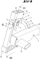
- a second support element 2 is pivotally arranged on the first support elements.
- the free end of the second support element 2 also carries a foot 37.
- the two second support elements 2 are connected by means of the connecting elements 35 rigidly together.
- the pivot axis 3, to which the second support member 2 of the in the FIG. 1 shown use position in a non-use position, not shown, is pivotable, is formed by a screw which passes through holes formed by two mutually parallel walls of the first support member 1 forming square tube.
- the connecting element 35 lies approximately in the pivot axis.
- the flange plate 11 On the second support member 2, a flange plate 11 is attached.
- the flange plate 11 has a broad side surface which bears against a broad side surface of the square tube 1.
- the broad side surface of the square tube 1 has a first slot-shaped window 13 and a second slot-shaped window 14.
- the head of a clamping element 6 protrudes through the first slot-shaped window 13.
- the clamping element 6 is a clamping lever, which is mounted pivotably about a pivot axis 16 on the first support element 1.
- the clamping lever 6 can be from a locking position, in the FIG. 9 is shown and in which the head of the clamping lever 6 protrudes from the window 13 on the broad side surface of the first support member 1, move in a release position, in the FIG. 10 is shown.
- the head of the clamping lever 6 is completely within the window 13.
- the obliquely cut end face 15 of the head of the clamping lever 6 lies here within the window 13 such that the flange plate 11 can slide over the slot-shaped window 13.
- a short end 17 of the clamping lever 6 protrudes from the second window 14 opposite the first window 13.
- the first support element 1 forms a square tube, with two first mutually parallel side walls, to which the pivot axis 3 extends in the transverse direction.
- Two second broad side surfaces of the first support element extend transversely to the first broad side surfaces. Transverse to the second broad side surfaces extends the pivot axis 16 about which the clamping element is pivotable.
- the two pivot axes 3, 16 are spaced apart in the extension direction of the first support element.
- the actuator 18 has two laterally projecting wings 23, 23 ', which can rest with play on the inner surfaces of the two shorter side surfaces of the support element 1.
- One of these shorter side walls carries the pivot axis 16 of the clamping element 6.
- the actuator 18 carries a locking pin 4, which protrudes from the window 14 from the cavity of the first support member.
- the locking pin 4 is in a detent niche 5 of the flange 11.
- At the detent niche 5 is followed by a circular arc around the pivot axis 3 extending guide edge 12 ', which is formed by the peripheral edge of an arcuate guide slot 12 is.
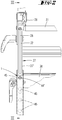
- the pivot axis 3 passes through an abutment 39, which is located within the first support element 1. It ties the abutment 39 to the first support element. At the abutment 39, one end of a tension spring 25 is attached. The other end of the tension spring 25 is attached to the actuator 18. The tension spring 25 acted upon the actuator 18 such that the locking pin 4 is held in the latching niche 5. On the actuating member 18 engages a pull rod 26 which extends through the tube cavity of the first support member 1 through into the tube cavity of the support member 27, where an actuating end of the tie rod 26 through a slot 32 which extends in the extension direction of the support member 27, from the Cavity of the support member 27 protrudes.
- a handle 31 is fixed, which extends parallel to the connecting element 38. If the handle 31 is pulled upwards, then the actuating member 18 also displaces upward, so that the latching pin 4 emerges from the latching niche 5. This is done against the restoring force of the spring 25.
- the abutment 39 has a lateral recess in which a bushing 41 engages.
- the bushing 41 passes through an opening of the wall of the support element 1 and an opening of the flange plate 11. An end edge of the bushing 41 is supported on the outside of the second support member 2 from.
- the opening 42 of the wall of the first support element 1 essentially surrounds the outer wall of the bushing 41, through which the pivot axis 3 extends.
- a shim 43 which holds the flange plate 11 slightly spaced from the outer wall of the support member 1.
- the wing 23 of the actuator 18 has a window 21 which is penetrated by movement play up and down from the clamping element 6. If the actuator 18 takes its locking position shown in the drawings, in which the locking pin 4 is located in the detent niche 5, the long lever arm of the clamping element 6 in the immediate vicinity of the slot 13 on the inside of the support element 1 of a pressure edge 19 of the window 21 down acted upon by the tensile force of the tension spring 25. If the actuating member 18 is displaced upward, then a clearance first takes place until the lifting flank 20 strikes the clamping element 6. At another Upward displacement of the actuator 18, the clamping member 6 about the pivot axis 16 of the in FIG. 9 illustrated locking position in the in FIG. 10 shifted released release position.
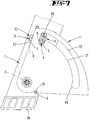
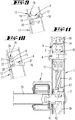
- FIGS. 4 and 7 show the holding elements, namely the locking pin 4, the latching niche 5, the clamping element 6, the clamping edge 7 and the stop 9 with counter-stop 10 in the locked position.
- the locking pin 4 is a tolerance-induced movement in the detent niche 5 a.
- the outer wall of a core surrounding the detent pin sleeve is spaced a slight distance from the wall 8 of the detent niche 5.
- the counter-stop 10 is in touching contact with the stop 9.
- the plane of movement B within which the clamping element 6 can pivotally displace forms a lying below the self-locking flat angle to the clamping edge 7, which is formed by a substantially rectilinear edge of the flange plate 11.
- the head of the clamping element 6 projecting out of the window 13 exerts a clamping force or a clamping force on the clamping flank 7.
- the torque introduced thereby into the flange plate 11 is transmitted to the stop 9.
- the head of the clamping element 6 is supported by a first section on the clamping edge 7. A portion of the clamping element 6 lying opposite this section is supported on a peripheral edge 13 'of the slot 13.
- the actuator 18 is brought by train on the handle 31 in an upwardly displaced position.
- the latching pin 4 is lifted out of the latching niche 5 into a release position.
- the clamping lever 6 is also in the in FIG. 10 shifted released release position.
- the second support element with respect to the representations in the FIGS. 7 and 8th be pivoted counterclockwise relative to the first support member 1.
- the end face 15 of the clamping lever 6 slides along a broad side surface of the flange plate 11 along.
- the locking pin 4 runs along the guide flank 12 'along. The actuator 18 can thus not be moved to its lowered position.
- a recess 40 into which the locking pin 5 can enter in a storage position of the second support member 2.
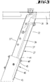
- first support element is located on the downwardly facing narrow side of the support member 1, a form-locking element 44.
- a form-locking element 44 is formed by the head of a countersunk screw.
- the threaded shaft of the countersunk screw passes through an opening of the narrow side wall of the first support element from the inside to the outside.
- the diameter of the opening is only slightly larger than the diameter of the threaded shank of the countersunk screw, so that the thread-fitting approach of the frusto-conical head 44 is supported on the inside edge of the opening.
- the majority of the head 44 thus projects into the square opening of the support element 1.
- On the outwardly projecting thread a nut 44 'is screwed.
- the clear opening between the two narrow side walls of the first support element is sufficiently larger than the distance between the outer sides of the facing away narrow sides 27 ', 27 "of the support member 27 so that the support member 27 can be brought by a pivoting movement into and out of engagement of a positive engagement with the form-locking means 44
- the countersunk head 44 engages in one of a plurality of openings 45 of the narrow side wall 27.
- An edge of the opening 45 lies on an upwardly pointing portion of the conical jacket wall portion of the countersunk head 44.
- the hook engagement can be canceled by a slight lifting movement
- the screw head 44 passes through the pivoting movement out of the opening 45, so that the support member 27 can be moved in its direction of extension. Along with this changes the altitude of the carrier 28.
- the support member 27 are slightly raised and then pivoted counterclockwise. It can then be moved in a slightly pivoted position both upwards, and downwards. By a pivoting movement in the clockwise direction, the positive locking member 44 can engage in another opening 45 of the support element.
- the spring 34 which has a rectangular cross-section, absorbs part of the weight of the carrier 28 and of the clamping jaws.
- the upper end of the helical spring 34 has a smaller cross-section than the lower portion of the spring element and stuck on a rectangular extension on the underside of the support element 27th
- a support frame which is characterized in that the holding elements 6, 7; 4, 5; 9, 10 have a one of the two support elements 1 associated clamping element 6 which abuts in the locking position on a clamping element 7 associated with the other support member 2 clamping edge.
- a support frame which is characterized in that the clamping element 6 is a lever pivotable about a pivot axis 16 which is arranged in particular in the interior of a hollow body formed by the first support member 1 and has a protruding through a window 13 from the cavity head, in a Swivel plane B is displaced, which extends at an acute angle to the clamping edge 7, which is formed in particular by a fixedly connected to the second support member 2 flange plate 11.
- a support frame which is characterized in that the holding means 6,7; 4, 5; 9, 10 in the first pivot position contacting contiguous fixed stops 9, 10 form, in particular the first support member 1, a stop 9 and the second support member 2 is associated with a counter-stop 10.
- a support frame which is characterized in that the holding elements 6, 7; 4, 5; 9, 10 have a latching pin 4, which rests in the locking position in a latching niche 5 and in particular together with the clamping element 6 is displaceable from the locking position to the release position.
- a support frame which is characterized in that the first support member 1 is a tubular body, with an arranged within the tube actuator 18 which is displaceable in particular against the force of a spring 25 in the extension direction of the first support member 1 and carrier of the locking pin 4 and in its displacement from the locking position into the release position, the clamping element 6 is displaced into the release position, wherein it is provided in particular that one arm of the clamping element 6 projects through a window 21 of the actuating member 18, which window 21 forms a lifting flank 20 and a pressure flank 19.
- a support frame which is characterized in that the clamping element 6 has an end face 15 which is supported during pivoting from the first pivot position to the second pivot position on a broad side surface of the flange 11, the pivoting of the two support members 1, 2 on the window 13th of the support element 1 pivots over.
- a support frame which is characterized in that the window 13 is a slot with a peripheral edge 13 'at which peripheral edge 13', the clamping element 6 is supported with a first portion, wherein a second portion pointing away from the first portion on the clamping edge 7 is supported.
- a support frame which is characterized in that the locking pin 4 rests with tolerance-related motion play in the latching niche 5, to which a guide edge 12 'connects, at which the brought into a release position locking pin 4 slides during pivoting of the support elements 1, 2 along.
- a support frame which is characterized in that the first support member 1 at its corresponding in one of the first pivot position use position the support frame downwardly facing end forms a first leg 36 that the second support member 2 is articulated in the immediate vicinity of the first foot 36 on the first support member 1 and forms a second foot 37 with its free end.
- a support frame which is characterized in that a support element pair 1, 2 four feet 36, 37 forming with connecting elements 35, 38 is connected to each other and the first support member 1 with its in the position of use upwardly facing end a support 28, in particular a clamping jaws 29th 30 carrying carrier 28 carries, and / or that in the clamping jaws 29, 30 transverse to an adjustment of the two clamping jaws 29, 30 extending longitudinal slots 47, 48 are provided.
- a support frame which is characterized in that in the cavity of the first support member 1, a support member 27 is telescopically arranged, in which an actuating end of an actuating member 18 acting on the tension element 26 is arranged, in particular provided that the support member 27 has a slot 32 through which an operating end of the pulling element 26 connected to a handle 31 protrudes.
- a support frame which is characterized in that the positive locking holding element 27 can be brought into and out of engagement with a latching opening 45 by a pivoting movement of the support element 27 relative to the support element 1.
- a support frame which is characterized in that the form-fitting retaining element 44 is formed by the head of a countersunk screw, which head 44 forms with its cone portion a hook, so that the positive locking member by a lifting / pivoting movement of the support member into and out of engagement in a detent opening 45 is brought.
- a support frame characterized in that the form-fitting engagement member 44 is disposed immediately adjacent to the edge of an opening of a pipe forming the support member 1 and fixed to the inner wall of the pipe.
- a support frame which is characterized in that on the plug-in support element 1 end of the support member, a support cam 46 is arranged, which protrudes from the wall of the support member 27 and is supported on the inside of the obliquely upwardly facing wall of the support element (1).
Landscapes
- Engineering & Computer Science (AREA)
- Mechanical Engineering (AREA)
- Mutual Connection Of Rods And Tubes (AREA)
- Clamps And Clips (AREA)
- Ladders (AREA)
Claims (13)
- Structure de support, en particulier table de travail/établi ou porte-pièces, comprenant un premier élément porteur (1), un deuxième élément porteur (2) articulé de manière pivotante à celui-ci et des éléments de maintien (6, 7 ; 4, 5 ; 9, 10) associés aux deux éléments porteurs (1, 2) qui, dans une position de verrouillage, fixent les deux éléments porteurs (1, 2) dans une première position de pivotement et, dans une position de libération, permettent le pivotement des éléments porteurs (1, 2) dans une deuxième position de pivotement, dans laquelle les éléments de maintien (6, 7 ; 4, 5 ; 9, 10) comprennent un élément de serrage (6) et une butée fixe (9) qui sont associés au premier élément porteur (1), dans laquelle l'élément de serrage (6), dans la position de verrouillage, prend appui avec serrage contre un flanc de serrage (7) du deuxième élément porteur (2), caractérisée en ce que le flanc de serrage (7) est un bord d'une plaque formant bride (11) qui est associée au deuxième élément porteur (2) et qui forme une contre-butée (10) pour la butée fixe (9).
- Structure de support selon la revendication 1, caractérisée en ce que l'élément de serrage (6) est un levier pivotant autour d'un axe de pivotement (16), qui est notamment agencé à l'intérieur d'un corps creux formé par le premier élément porteur (1) et présente une tête dépassant de la cavité par une fenêtre (13), qui peut être déplacée dans un plan de pivotement (B) formant un angle aigu avec le flanc de serrage (7).
- Structure de support selon l'une des revendications précédentes, caractérisée en ce que les éléments de maintien (6, 7 ; 4, 5 ; 9, 10) comprennent une goupille d'encliquetage (4) qui, dans la position de verrouillage, est placée dans une niche d'encliquetage (5) et qui peut, en particulier, être déplacée ensemble avec l'élément de serrage (6) de la position de verrouillage dans la position de libération.
- Structure de support selon la revendication 3, caractérisée en ce que le premier élément porteur (1) est un corps tubulaire avec un organe d'actionnement (18) agencé à l'intérieur du tube, lequel notamment peut être déplacé à l'encontre de la force d'un ressort (25) dans la direction d'extension du premier élément porteur (1) et porte la goupille d'encliquetage (4) et qui lors de son déplacement de la position de verrouillage dans la position de libération, déplace l'élément de serrage (6) dans la position de libération, dans laquelle il est prévu en particulier qu'un bras de l'élément de serrage (6) fait saillie à travers une fenêtre (21) de l'organe d'actionnement (18) laquelle fenêtre (21) forme un flanc de levage (20) et un flanc de pression (19).
- Structure de support selon l'une des revendications 2 à 4, caractérisée en ce que l'élément de serrage (6) présente une surface frontale (15) qui, lors du pivotement de la première position de pivotement dans la deuxième position de pivotement, prend appui sur une face large de la plaque formant bride (11) qui passe par pivotement devant la fenêtre (13) de l'élément porteur (1) lors du pivotement des deux éléments porteurs (1, 2).
- Structure de support selon l'une des revendications 2 à 5, caractérisée en ce que la fenêtre (13) est une fente avec un bord (13') sur lequel s'appuie l'élément de serrage (6) avec une première partie, une deuxième partie dirigée à l'opposé de la première partie s'appuyant sur le flanc de serrage (7).
- Structure de support selon l'une des revendications 3 à 6, caractérisée en ce que la goupille d'encliquetage (4) est placée avec un jeu de mouvement déterminé par tolérancement dans la niche d'encliquetage (5) à laquelle se raccorde un flanc de guidage (12') le long duquel glisse, lors du pivotement des éléments porteurs (1,2), la goupille d'encliquetage (4) qui a été amenée dans une position de libération.
- Structure de support selon l'une des revendications précédentes, caractérisé en ce que dans une position d'utilisation de la structure de support correspondant à la première position de pivotement, le premier élément porteur (1) forme un premier pied (36) à son extrémité dirigée vers le bas, et en ce que le deuxième élément porteur (2) est articulé au premier élément porteur (1) au voisinage immédiat du premier pied (36) et forme un deuxième pied (37) avec son extrémité libre.
- Structure de support selon l'une des revendications précédentes, caractérisée en ce qu'une paire d'éléments porteurs (1, 2) formant quatre pieds (36, 37) sont reliés l'un à l'autre par des éléments de liaison (35, 38) et en position d'utilisation, le premier élément porteur (1) porte avec son extrémité dirigée vers le haut un support (28), en particulier un support (28) portant des mâchoires de serrage (29, 30), et/ou en ce que sont prévues dans les mâchoires de serrage (29, 30) des fentes longitudinales (47, 48) s'étendant transversalement à une direction de déplacement des deux mâchoires de serrage (29, 30).
- Structure de support selon l'une des revendications précédentes, caractérisée en ce qu'est agencé dans la cavité du premier élément porteur (1), un élément de support télescopique (27) dans lequel est agencée une extrémité d'actionnement d'un élément de traction (26) agissant sur l'élément d'actionnement (18), dans laquelle est prévue notamment que l'élément de support (27) présente une fente (32) à travers laquelle fait saillie une extrémité d'actionnement de l'élément de traction (26) qui est reliée à une poignée (31).
- Structure de support selon l'une des revendications précédentes, caractérisée par une structure inférieure pouvant être disposée sur un sol et qui présente au moins un élément porteur allongé (1) qui s'étend obliquement vers le haut dans un plan vertical et dans lequel est inséré de manière télescopique un élément de support allongé (27) à l'extrémité supérieure duquel est fixé un support (28), dans laquelle l'élément de support (27) peut être fixé à l'élément porteur (1) à différentes positions de hauteur du support (28) au moyen d'un élément de retenue à coopération de forme (44) s'engageant dans une ouverture d'encliquetage (45), dans laquelle l'élément de retenue à coopération de forme peut être engagé dans une ouverture d'encliquetage (45) et dégagé de celle-ci par un mouvement pivotant de l'élément de support (27) par rapport à l'élément porteur (1).
- Structure de support selon la revendication 11, caractérisée en ce que l'élément de retenue à coopération de forme (44) est formé par la tête d'une vis à tête fraisée, laquelle tête (44) forme un crochet avec sa partie conique de manière que l'élément de retenue à coopération de forme puisse être engagé dans une ouverture d'encliquetage (45) et dégagé de celle-ci par un mouvement de levage/pivotement de l'élément de support.
- Structure de support selon la revendication 12 ou 13, caractérisée en ce que l'élément d'engagement à coopération de forme (44) est agencé directement adjacent au bord d'une ouverture d'un tube formant l'élément porteur (1) et est fixé à la paroi intérieure du tube et/ou en ce qu'est agencé à l'extrémité de l'élément de support qui est introduite dans l'élément porteur (1), un ergot d'appui (46) qui fait saillie depuis la paroi de l'élément de support (27) et qui prend appui sur la face intérieure de la paroi de l'élément porteur (1) dirigée obliquement vers le haut.
Priority Applications (1)
| Application Number | Priority Date | Filing Date | Title |
|---|---|---|---|
| EP19187378.5A EP3593953B1 (fr) | 2014-05-16 | 2015-05-07 | Structure de support doté d'éléments porteurs pouvant être verrouillés sans cliquetis |
Applications Claiming Priority (1)
| Application Number | Priority Date | Filing Date | Title |
|---|---|---|---|
| DE102014106961.7A DE102014106961A1 (de) | 2014-05-16 | 2014-05-16 | Tragegestell mit klapperfrei verriegelbaren Tragelementen |
Related Child Applications (2)
| Application Number | Title | Priority Date | Filing Date |
|---|---|---|---|
| EP19187378.5A Division EP3593953B1 (fr) | 2014-05-16 | 2015-05-07 | Structure de support doté d'éléments porteurs pouvant être verrouillés sans cliquetis |
| EP19187378.5A Division-Into EP3593953B1 (fr) | 2014-05-16 | 2015-05-07 | Structure de support doté d'éléments porteurs pouvant être verrouillés sans cliquetis |
Publications (3)
| Publication Number | Publication Date |
|---|---|
| EP2944436A2 EP2944436A2 (fr) | 2015-11-18 |
| EP2944436A3 EP2944436A3 (fr) | 2016-12-14 |
| EP2944436B1 true EP2944436B1 (fr) | 2019-11-13 |
Family
ID=53268623
Family Applications (2)
| Application Number | Title | Priority Date | Filing Date |
|---|---|---|---|
| EP15166717.7A Active EP2944436B1 (fr) | 2014-05-16 | 2015-05-07 | Structure de support doté d'éléments porteurs pouvant être verrouillés sans cliquetis |
| EP19187378.5A Active EP3593953B1 (fr) | 2014-05-16 | 2015-05-07 | Structure de support doté d'éléments porteurs pouvant être verrouillés sans cliquetis |
Family Applications After (1)
| Application Number | Title | Priority Date | Filing Date |
|---|---|---|---|
| EP19187378.5A Active EP3593953B1 (fr) | 2014-05-16 | 2015-05-07 | Structure de support doté d'éléments porteurs pouvant être verrouillés sans cliquetis |
Country Status (3)
| Country | Link |
|---|---|
| EP (2) | EP2944436B1 (fr) |
| DE (1) | DE102014106961A1 (fr) |
| ES (1) | ES2872174T3 (fr) |
Families Citing this family (9)
| Publication number | Priority date | Publication date | Assignee | Title |
|---|---|---|---|---|
| CN105598928A (zh) * | 2016-02-25 | 2016-05-25 | 莫焕东 | 一种角度可调的新型智能工作台装置 |
| CN105598930A (zh) * | 2016-02-25 | 2016-05-25 | 任泽威 | 一种由螺杆控制且角度可调的工作台机构 |
| CN105598710A (zh) * | 2016-02-25 | 2016-05-25 | 莫焕东 | 一种角度可调且操作便捷的工作平台 |
| CN108656570B (zh) * | 2018-04-18 | 2024-03-08 | 中储粮成都储藏研究院有限公司 | 一种粮膜密封压槽管装置 |
| CN108908227A (zh) * | 2018-05-31 | 2018-11-30 | 河南欧文包装制品有限公司 | 一种一次性餐盒生产加工工作平台 |
| CN110762363B (zh) * | 2019-10-22 | 2024-08-13 | 浙江华丰电动工具有限公司 | 一体折叠脚架 |
| CN111645042B (zh) * | 2020-05-09 | 2021-11-30 | 泰州市光明电子材料有限公司 | 一种汽车电子产品生产用便于调节角度的工作台 |
| CN112518687B (zh) * | 2020-12-08 | 2022-08-09 | 深圳市韩安特科技有限公司 | 显示屏承载装置 |
| CN215920370U (zh) * | 2021-04-21 | 2022-03-01 | 杭州巨星科技股份有限公司 | 一种锯架 |
Family Cites Families (11)
| Publication number | Priority date | Publication date | Assignee | Title |
|---|---|---|---|---|
| CH347966A (de) | 1957-03-02 | 1960-07-31 | Egger Fritz | Zusammenlegbarer Unterstellbock |
| GB1267032A (fr) | 1968-03-04 | 1972-03-15 | ||
| US4144822A (en) | 1977-01-24 | 1979-03-20 | Roberts Mfg., Inc. | Folding leg mechanism |
| DE19735336A1 (de) | 1997-08-14 | 1999-02-18 | Wolfcraft Gmbh | Werktisch |
| IL125793A (en) * | 1998-08-14 | 2003-05-29 | Z A G Ind Ltd | Height and working width adjustable sawhorse |
| DE19909830A1 (de) | 1999-03-05 | 2000-09-07 | Wolfcraft Gmbh | Werktisch |
| US6712180B2 (en) * | 2002-03-01 | 2004-03-30 | Zag Industries Ltd. | Height adjustable sawhorse |
| US6883793B2 (en) | 2002-09-17 | 2005-04-26 | Black & Decker Inc. | Portable workbench having collapsible support structure |
| CN2649283Y (zh) * | 2003-07-17 | 2004-10-20 | 南京泉峰国际贸易有限公司 | 用于切割机器的可折叠支架 |
| US20050051940A1 (en) * | 2003-09-05 | 2005-03-10 | Zag Industries, Ltd. | Work stand |
| EP2599595B1 (fr) * | 2011-12-01 | 2017-10-11 | The Stanley Works Israel Ltd. | Chevalet de sciage réglable |
-
2014
- 2014-05-16 DE DE102014106961.7A patent/DE102014106961A1/de active Pending
-
2015
- 2015-05-07 EP EP15166717.7A patent/EP2944436B1/fr active Active
- 2015-05-07 ES ES19187378T patent/ES2872174T3/es active Active
- 2015-05-07 EP EP19187378.5A patent/EP3593953B1/fr active Active
Non-Patent Citations (1)
| Title |
|---|
| None * |
Also Published As
| Publication number | Publication date |
|---|---|
| DE102014106961A1 (de) | 2015-11-19 |
| ES2872174T3 (es) | 2021-11-02 |
| EP2944436A2 (fr) | 2015-11-18 |
| EP3593953A1 (fr) | 2020-01-15 |
| EP2944436A3 (fr) | 2016-12-14 |
| EP3593953B1 (fr) | 2021-04-14 |
Similar Documents
| Publication | Publication Date | Title |
|---|---|---|
| EP2944436B1 (fr) | Structure de support doté d'éléments porteurs pouvant être verrouillés sans cliquetis | |
| EP2222202B1 (fr) | Tiroir avec réglage du panneau avant | |
| EP2851497B1 (fr) | Dispositif de montage réglable pour un élément coulissant et dispositif coulissant | |
| EP3215099B1 (fr) | Griffe de serrage à poser sur une glissière pour table d'opération | |
| DE102010060722B4 (de) | Verbindungsbeschlag | |
| DE102007008951B4 (de) | Tischtennistisch | |
| DE112013007025B4 (de) | Verriegelungsvorrichtung für teleskopierbare Möbelsäule, Möbel und Verfahren | |
| EP3138674B1 (fr) | Dispositif de coupe en onglet | |
| WO2010136228A1 (fr) | Dispositif de fixation d'une façade avant à un flanc latéral d'une partie mobile de meuble, tiroir et meuble | |
| DE202009014811U1 (de) | Möbelbeschlag zum lösbaren Verbinden zweier Möbelteile | |
| WO2012159990A1 (fr) | Charnière | |
| DE102008060126A1 (de) | Spannsystem | |
| EP2710210A1 (fr) | Ferrure pour porte coulissante | |
| EP4417546A1 (fr) | Colonne d'empilement | |
| CH716837A1 (de) | Windverband und Möbelbausatz. | |
| AT519906A1 (de) | Möbelscharnier | |
| EP1877713B1 (fr) | Appareil de réfrigération et/ou de congélation | |
| AT507690B1 (de) | Möbelbeschlag zum lösbaren verbinden zweier möbelteile | |
| DE102014210314A1 (de) | Befestigungsvorrichtung zur Befestigung eines Gegenstandes an einer Wand und Befestigungssystem | |
| DE102013218868A1 (de) | Betätigungsanordnung sowie Entriegelungshebel hierfür | |
| EP2233039B1 (fr) | Guidage pour tiroirs | |
| WO2009112140A1 (fr) | Procédé de fixation d'un objet sur un rail | |
| EP1794053B1 (fr) | Dispositif de fixation d'un objet sur un rail | |
| EP4190492A1 (fr) | Système d'adaptateur d'établi pour établis pourvus de grille perforée | |
| AT525757B1 (de) | Verriegelungsvorrichtung für eine verlagerbare Bunkerwand |
Legal Events
| Date | Code | Title | Description |
|---|---|---|---|
| PUAI | Public reference made under article 153(3) epc to a published international application that has entered the european phase |
Free format text: ORIGINAL CODE: 0009012 |
|
| AK | Designated contracting states |
Kind code of ref document: A2 Designated state(s): AL AT BE BG CH CY CZ DE DK EE ES FI FR GB GR HR HU IE IS IT LI LT LU LV MC MK MT NL NO PL PT RO RS SE SI SK SM TR |
|
| AX | Request for extension of the european patent |
Extension state: BA ME |
|
| PUAL | Search report despatched |
Free format text: ORIGINAL CODE: 0009013 |
|
| AK | Designated contracting states |
Kind code of ref document: A3 Designated state(s): AL AT BE BG CH CY CZ DE DK EE ES FI FR GB GR HR HU IE IS IT LI LT LU LV MC MK MT NL NO PL PT RO RS SE SI SK SM TR |
|
| AX | Request for extension of the european patent |
Extension state: BA ME |
|
| RIC1 | Information provided on ipc code assigned before grant |
Ipc: B25H 1/04 20060101AFI20161107BHEP Ipc: B25H 1/16 20060101ALI20161107BHEP |
|
| STAA | Information on the status of an ep patent application or granted ep patent |
Free format text: STATUS: REQUEST FOR EXAMINATION WAS MADE |
|
| 17P | Request for examination filed |
Effective date: 20170327 |
|
| RBV | Designated contracting states (corrected) |
Designated state(s): AL AT BE BG CH CY CZ DE DK EE ES FI FR GB GR HR HU IE IS IT LI LT LU LV MC MK MT NL NO PL PT RO RS SE SI SK SM TR |
|
| GRAP | Despatch of communication of intention to grant a patent |
Free format text: ORIGINAL CODE: EPIDOSNIGR1 |
|
| STAA | Information on the status of an ep patent application or granted ep patent |
Free format text: STATUS: GRANT OF PATENT IS INTENDED |
|
| INTG | Intention to grant announced |
Effective date: 20190424 |
|
| GRAS | Grant fee paid |
Free format text: ORIGINAL CODE: EPIDOSNIGR3 |
|
| GRAJ | Information related to disapproval of communication of intention to grant by the applicant or resumption of examination proceedings by the epo deleted |
Free format text: ORIGINAL CODE: EPIDOSDIGR1 |
|
| GRAL | Information related to payment of fee for publishing/printing deleted |
Free format text: ORIGINAL CODE: EPIDOSDIGR3 |
|
| STAA | Information on the status of an ep patent application or granted ep patent |
Free format text: STATUS: REQUEST FOR EXAMINATION WAS MADE |
|
| INTC | Intention to grant announced (deleted) | ||
| GRAR | Information related to intention to grant a patent recorded |
Free format text: ORIGINAL CODE: EPIDOSNIGR71 |
|
| STAA | Information on the status of an ep patent application or granted ep patent |
Free format text: STATUS: GRANT OF PATENT IS INTENDED |
|
| GRAA | (expected) grant |
Free format text: ORIGINAL CODE: 0009210 |
|
| STAA | Information on the status of an ep patent application or granted ep patent |
Free format text: STATUS: THE PATENT HAS BEEN GRANTED |
|
| INTG | Intention to grant announced |
Effective date: 20191002 |
|
| AK | Designated contracting states |
Kind code of ref document: B1 Designated state(s): AL AT BE BG CH CY CZ DE DK EE ES FI FR GB GR HR HU IE IS IT LI LT LU LV MC MK MT NL NO PL PT RO RS SE SI SK SM TR |
|
| REG | Reference to a national code |
Ref country code: CH Ref legal event code: EP Ref country code: AT Ref legal event code: REF Ref document number: 1201177 Country of ref document: AT Kind code of ref document: T Effective date: 20191115 |
|
| REG | Reference to a national code |
Ref country code: DE Ref legal event code: R096 Ref document number: 502015010901 Country of ref document: DE |
|
| REG | Reference to a national code |
Ref country code: IE Ref legal event code: FG4D Free format text: LANGUAGE OF EP DOCUMENT: GERMAN |
|
| REG | Reference to a national code |
Ref country code: NL Ref legal event code: MP Effective date: 20191113 |
|
| REG | Reference to a national code |
Ref country code: LT Ref legal event code: MG4D |
|
| PG25 | Lapsed in a contracting state [announced via postgrant information from national office to epo] |
Ref country code: NL Free format text: LAPSE BECAUSE OF FAILURE TO SUBMIT A TRANSLATION OF THE DESCRIPTION OR TO PAY THE FEE WITHIN THE PRESCRIBED TIME-LIMIT Effective date: 20191113 Ref country code: BG Free format text: LAPSE BECAUSE OF FAILURE TO SUBMIT A TRANSLATION OF THE DESCRIPTION OR TO PAY THE FEE WITHIN THE PRESCRIBED TIME-LIMIT Effective date: 20200213 Ref country code: GR Free format text: LAPSE BECAUSE OF FAILURE TO SUBMIT A TRANSLATION OF THE DESCRIPTION OR TO PAY THE FEE WITHIN THE PRESCRIBED TIME-LIMIT Effective date: 20200214 Ref country code: FI Free format text: LAPSE BECAUSE OF FAILURE TO SUBMIT A TRANSLATION OF THE DESCRIPTION OR TO PAY THE FEE WITHIN THE PRESCRIBED TIME-LIMIT Effective date: 20191113 Ref country code: LT Free format text: LAPSE BECAUSE OF FAILURE TO SUBMIT A TRANSLATION OF THE DESCRIPTION OR TO PAY THE FEE WITHIN THE PRESCRIBED TIME-LIMIT Effective date: 20191113 Ref country code: LV Free format text: LAPSE BECAUSE OF FAILURE TO SUBMIT A TRANSLATION OF THE DESCRIPTION OR TO PAY THE FEE WITHIN THE PRESCRIBED TIME-LIMIT Effective date: 20191113 Ref country code: SE Free format text: LAPSE BECAUSE OF FAILURE TO SUBMIT A TRANSLATION OF THE DESCRIPTION OR TO PAY THE FEE WITHIN THE PRESCRIBED TIME-LIMIT Effective date: 20191113 Ref country code: PL Free format text: LAPSE BECAUSE OF FAILURE TO SUBMIT A TRANSLATION OF THE DESCRIPTION OR TO PAY THE FEE WITHIN THE PRESCRIBED TIME-LIMIT Effective date: 20191113 Ref country code: NO Free format text: LAPSE BECAUSE OF FAILURE TO SUBMIT A TRANSLATION OF THE DESCRIPTION OR TO PAY THE FEE WITHIN THE PRESCRIBED TIME-LIMIT Effective date: 20200213 Ref country code: PT Free format text: LAPSE BECAUSE OF FAILURE TO SUBMIT A TRANSLATION OF THE DESCRIPTION OR TO PAY THE FEE WITHIN THE PRESCRIBED TIME-LIMIT Effective date: 20200313 |
|
| PG25 | Lapsed in a contracting state [announced via postgrant information from national office to epo] |
Ref country code: RS Free format text: LAPSE BECAUSE OF FAILURE TO SUBMIT A TRANSLATION OF THE DESCRIPTION OR TO PAY THE FEE WITHIN THE PRESCRIBED TIME-LIMIT Effective date: 20191113 Ref country code: HR Free format text: LAPSE BECAUSE OF FAILURE TO SUBMIT A TRANSLATION OF THE DESCRIPTION OR TO PAY THE FEE WITHIN THE PRESCRIBED TIME-LIMIT Effective date: 20191113 Ref country code: IS Free format text: LAPSE BECAUSE OF FAILURE TO SUBMIT A TRANSLATION OF THE DESCRIPTION OR TO PAY THE FEE WITHIN THE PRESCRIBED TIME-LIMIT Effective date: 20200313 |
|
| PG25 | Lapsed in a contracting state [announced via postgrant information from national office to epo] |
Ref country code: AL Free format text: LAPSE BECAUSE OF FAILURE TO SUBMIT A TRANSLATION OF THE DESCRIPTION OR TO PAY THE FEE WITHIN THE PRESCRIBED TIME-LIMIT Effective date: 20191113 |
|
| PG25 | Lapsed in a contracting state [announced via postgrant information from national office to epo] |
Ref country code: RO Free format text: LAPSE BECAUSE OF FAILURE TO SUBMIT A TRANSLATION OF THE DESCRIPTION OR TO PAY THE FEE WITHIN THE PRESCRIBED TIME-LIMIT Effective date: 20191113 Ref country code: CZ Free format text: LAPSE BECAUSE OF FAILURE TO SUBMIT A TRANSLATION OF THE DESCRIPTION OR TO PAY THE FEE WITHIN THE PRESCRIBED TIME-LIMIT Effective date: 20191113 Ref country code: ES Free format text: LAPSE BECAUSE OF FAILURE TO SUBMIT A TRANSLATION OF THE DESCRIPTION OR TO PAY THE FEE WITHIN THE PRESCRIBED TIME-LIMIT Effective date: 20191113 Ref country code: EE Free format text: LAPSE BECAUSE OF FAILURE TO SUBMIT A TRANSLATION OF THE DESCRIPTION OR TO PAY THE FEE WITHIN THE PRESCRIBED TIME-LIMIT Effective date: 20191113 Ref country code: DK Free format text: LAPSE BECAUSE OF FAILURE TO SUBMIT A TRANSLATION OF THE DESCRIPTION OR TO PAY THE FEE WITHIN THE PRESCRIBED TIME-LIMIT Effective date: 20191113 |
|
| REG | Reference to a national code |
Ref country code: DE Ref legal event code: R097 Ref document number: 502015010901 Country of ref document: DE |
|
| PG25 | Lapsed in a contracting state [announced via postgrant information from national office to epo] |
Ref country code: SK Free format text: LAPSE BECAUSE OF FAILURE TO SUBMIT A TRANSLATION OF THE DESCRIPTION OR TO PAY THE FEE WITHIN THE PRESCRIBED TIME-LIMIT Effective date: 20191113 Ref country code: SM Free format text: LAPSE BECAUSE OF FAILURE TO SUBMIT A TRANSLATION OF THE DESCRIPTION OR TO PAY THE FEE WITHIN THE PRESCRIBED TIME-LIMIT Effective date: 20191113 |
|
| PLBE | No opposition filed within time limit |
Free format text: ORIGINAL CODE: 0009261 |
|
| STAA | Information on the status of an ep patent application or granted ep patent |
Free format text: STATUS: NO OPPOSITION FILED WITHIN TIME LIMIT |
|
| 26N | No opposition filed |
Effective date: 20200814 |
|
| PG25 | Lapsed in a contracting state [announced via postgrant information from national office to epo] |
Ref country code: SI Free format text: LAPSE BECAUSE OF FAILURE TO SUBMIT A TRANSLATION OF THE DESCRIPTION OR TO PAY THE FEE WITHIN THE PRESCRIBED TIME-LIMIT Effective date: 20191113 |
|
| PG25 | Lapsed in a contracting state [announced via postgrant information from national office to epo] |
Ref country code: CH Free format text: LAPSE BECAUSE OF NON-PAYMENT OF DUE FEES Effective date: 20200531 Ref country code: LI Free format text: LAPSE BECAUSE OF NON-PAYMENT OF DUE FEES Effective date: 20200531 Ref country code: MC Free format text: LAPSE BECAUSE OF FAILURE TO SUBMIT A TRANSLATION OF THE DESCRIPTION OR TO PAY THE FEE WITHIN THE PRESCRIBED TIME-LIMIT Effective date: 20191113 Ref country code: IT Free format text: LAPSE BECAUSE OF FAILURE TO SUBMIT A TRANSLATION OF THE DESCRIPTION OR TO PAY THE FEE WITHIN THE PRESCRIBED TIME-LIMIT Effective date: 20191113 |
|
| REG | Reference to a national code |
Ref country code: BE Ref legal event code: MM Effective date: 20200531 |
|
| PG25 | Lapsed in a contracting state [announced via postgrant information from national office to epo] |
Ref country code: LU Free format text: LAPSE BECAUSE OF NON-PAYMENT OF DUE FEES Effective date: 20200507 |
|
| PG25 | Lapsed in a contracting state [announced via postgrant information from national office to epo] |
Ref country code: IE Free format text: LAPSE BECAUSE OF NON-PAYMENT OF DUE FEES Effective date: 20200507 |
|
| PG25 | Lapsed in a contracting state [announced via postgrant information from national office to epo] |
Ref country code: BE Free format text: LAPSE BECAUSE OF NON-PAYMENT OF DUE FEES Effective date: 20200531 |
|
| REG | Reference to a national code |
Ref country code: AT Ref legal event code: MM01 Ref document number: 1201177 Country of ref document: AT Kind code of ref document: T Effective date: 20200507 |
|
| PG25 | Lapsed in a contracting state [announced via postgrant information from national office to epo] |
Ref country code: AT Free format text: LAPSE BECAUSE OF NON-PAYMENT OF DUE FEES Effective date: 20200507 |
|
| PG25 | Lapsed in a contracting state [announced via postgrant information from national office to epo] |
Ref country code: TR Free format text: LAPSE BECAUSE OF FAILURE TO SUBMIT A TRANSLATION OF THE DESCRIPTION OR TO PAY THE FEE WITHIN THE PRESCRIBED TIME-LIMIT Effective date: 20191113 Ref country code: MT Free format text: LAPSE BECAUSE OF FAILURE TO SUBMIT A TRANSLATION OF THE DESCRIPTION OR TO PAY THE FEE WITHIN THE PRESCRIBED TIME-LIMIT Effective date: 20191113 Ref country code: CY Free format text: LAPSE BECAUSE OF FAILURE TO SUBMIT A TRANSLATION OF THE DESCRIPTION OR TO PAY THE FEE WITHIN THE PRESCRIBED TIME-LIMIT Effective date: 20191113 |
|
| PG25 | Lapsed in a contracting state [announced via postgrant information from national office to epo] |
Ref country code: MK Free format text: LAPSE BECAUSE OF FAILURE TO SUBMIT A TRANSLATION OF THE DESCRIPTION OR TO PAY THE FEE WITHIN THE PRESCRIBED TIME-LIMIT Effective date: 20191113 |
|
| P01 | Opt-out of the competence of the unified patent court (upc) registered |
Effective date: 20230513 |
|
| PGFP | Annual fee paid to national office [announced via postgrant information from national office to epo] |
Ref country code: DE Payment date: 20250516 Year of fee payment: 11 |
|
| PGFP | Annual fee paid to national office [announced via postgrant information from national office to epo] |
Ref country code: GB Payment date: 20250516 Year of fee payment: 11 |
|
| PGFP | Annual fee paid to national office [announced via postgrant information from national office to epo] |
Ref country code: FR Payment date: 20250516 Year of fee payment: 11 |