EP2944764B1 - Bauteil eines gasturbinentriebwerks, zugehöriges gasturbinentriebwerk und kühlverfahren - Google Patents
Bauteil eines gasturbinentriebwerks, zugehöriges gasturbinentriebwerk und kühlverfahren Download PDFInfo
- Publication number
- EP2944764B1 EP2944764B1 EP15001485.0A EP15001485A EP2944764B1 EP 2944764 B1 EP2944764 B1 EP 2944764B1 EP 15001485 A EP15001485 A EP 15001485A EP 2944764 B1 EP2944764 B1 EP 2944764B1
- Authority
- EP
- European Patent Office
- Prior art keywords
- heat transfer
- tip
- tip pocket
- component
- transfer augmentation
- Prior art date
- Legal status (The legal status is an assumption and is not a legal conclusion. Google has not performed a legal analysis and makes no representation as to the accuracy of the status listed.)
- Active
Links
Images


Classifications
-
- F—MECHANICAL ENGINEERING; LIGHTING; HEATING; WEAPONS; BLASTING
- F01—MACHINES OR ENGINES IN GENERAL; ENGINE PLANTS IN GENERAL; STEAM ENGINES
- F01D—NON-POSITIVE DISPLACEMENT MACHINES OR ENGINES, e.g. STEAM TURBINES
- F01D5/00—Blades; Blade-carrying members; Heating, heat-insulating, cooling or antivibration means on the blades or the members
- F01D5/12—Blades
- F01D5/14—Form or construction
- F01D5/18—Hollow blades, i.e. blades with cooling or heating channels or cavities; Heating, heat-insulating or cooling means on blades
- F01D5/187—Convection cooling
-
- F—MECHANICAL ENGINEERING; LIGHTING; HEATING; WEAPONS; BLASTING
- F01—MACHINES OR ENGINES IN GENERAL; ENGINE PLANTS IN GENERAL; STEAM ENGINES
- F01D—NON-POSITIVE DISPLACEMENT MACHINES OR ENGINES, e.g. STEAM TURBINES
- F01D5/00—Blades; Blade-carrying members; Heating, heat-insulating, cooling or antivibration means on the blades or the members
- F01D5/12—Blades
- F01D5/14—Form or construction
- F01D5/20—Specially-shaped blade tips to seal space between tips and stator
-
- F—MECHANICAL ENGINEERING; LIGHTING; HEATING; WEAPONS; BLASTING
- F01—MACHINES OR ENGINES IN GENERAL; ENGINE PLANTS IN GENERAL; STEAM ENGINES
- F01D—NON-POSITIVE DISPLACEMENT MACHINES OR ENGINES, e.g. STEAM TURBINES
- F01D5/00—Blades; Blade-carrying members; Heating, heat-insulating, cooling or antivibration means on the blades or the members
- F01D5/12—Blades
- F01D5/14—Form or construction
- F01D5/147—Construction, i.e. structural features, e.g. of weight-saving hollow blades
-
- F—MECHANICAL ENGINEERING; LIGHTING; HEATING; WEAPONS; BLASTING
- F01—MACHINES OR ENGINES IN GENERAL; ENGINE PLANTS IN GENERAL; STEAM ENGINES
- F01D—NON-POSITIVE DISPLACEMENT MACHINES OR ENGINES, e.g. STEAM TURBINES
- F01D5/00—Blades; Blade-carrying members; Heating, heat-insulating, cooling or antivibration means on the blades or the members
- F01D5/12—Blades
- F01D5/14—Form or construction
- F01D5/18—Hollow blades, i.e. blades with cooling or heating channels or cavities; Heating, heat-insulating or cooling means on blades
- F01D5/186—Film cooling
-
- F—MECHANICAL ENGINEERING; LIGHTING; HEATING; WEAPONS; BLASTING
- F05—INDEXING SCHEMES RELATING TO ENGINES OR PUMPS IN VARIOUS SUBCLASSES OF CLASSES F01-F04
- F05D—INDEXING SCHEME FOR ASPECTS RELATING TO NON-POSITIVE-DISPLACEMENT MACHINES OR ENGINES, GAS-TURBINES OR JET-PROPULSION PLANTS
- F05D2220/00—Application
- F05D2220/30—Application in turbines
- F05D2220/32—Application in turbines in gas turbines
-
- F—MECHANICAL ENGINEERING; LIGHTING; HEATING; WEAPONS; BLASTING
- F05—INDEXING SCHEMES RELATING TO ENGINES OR PUMPS IN VARIOUS SUBCLASSES OF CLASSES F01-F04
- F05D—INDEXING SCHEME FOR ASPECTS RELATING TO NON-POSITIVE-DISPLACEMENT MACHINES OR ENGINES, GAS-TURBINES OR JET-PROPULSION PLANTS
- F05D2260/00—Function
- F05D2260/20—Heat transfer, e.g. cooling
- F05D2260/202—Heat transfer, e.g. cooling by film cooling
-
- F—MECHANICAL ENGINEERING; LIGHTING; HEATING; WEAPONS; BLASTING
- F05—INDEXING SCHEMES RELATING TO ENGINES OR PUMPS IN VARIOUS SUBCLASSES OF CLASSES F01-F04
- F05D—INDEXING SCHEME FOR ASPECTS RELATING TO NON-POSITIVE-DISPLACEMENT MACHINES OR ENGINES, GAS-TURBINES OR JET-PROPULSION PLANTS
- F05D2260/00—Function
- F05D2260/20—Heat transfer, e.g. cooling
- F05D2260/221—Improvement of heat transfer
- F05D2260/2212—Improvement of heat transfer by creating turbulence
-
- F—MECHANICAL ENGINEERING; LIGHTING; HEATING; WEAPONS; BLASTING
- F05—INDEXING SCHEMES RELATING TO ENGINES OR PUMPS IN VARIOUS SUBCLASSES OF CLASSES F01-F04
- F05D—INDEXING SCHEME FOR ASPECTS RELATING TO NON-POSITIVE-DISPLACEMENT MACHINES OR ENGINES, GAS-TURBINES OR JET-PROPULSION PLANTS
- F05D2260/00—Function
- F05D2260/20—Heat transfer, e.g. cooling
- F05D2260/221—Improvement of heat transfer
- F05D2260/2214—Improvement of heat transfer by increasing the heat transfer surface
- F05D2260/22141—Improvement of heat transfer by increasing the heat transfer surface using fins or ribs
-
- Y—GENERAL TAGGING OF NEW TECHNOLOGICAL DEVELOPMENTS; GENERAL TAGGING OF CROSS-SECTIONAL TECHNOLOGIES SPANNING OVER SEVERAL SECTIONS OF THE IPC; TECHNICAL SUBJECTS COVERED BY FORMER USPC CROSS-REFERENCE ART COLLECTIONS [XRACs] AND DIGESTS
- Y02—TECHNOLOGIES OR APPLICATIONS FOR MITIGATION OR ADAPTATION AGAINST CLIMATE CHANGE
- Y02T—CLIMATE CHANGE MITIGATION TECHNOLOGIES RELATED TO TRANSPORTATION
- Y02T50/00—Aeronautics or air transport
- Y02T50/60—Efficient propulsion technologies, e.g. for aircraft
Definitions
- cooling circuits that channel dedicated cooling fluids for cooling the component. It can be difficult to communicate enough cooling fluid to cool airfoil tips of the components. This may lead to airfoil tip burning.
- the present invention provides a gas turbine engine component as set forth in claim 1.
- the heat transfer augmentation device axially extends across at least one of the suction side lip and the pressure side lip.
- the heat transfer augmentation device is slanted toward either the leading edge lip or the trailing edge lip.
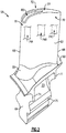
- the component 58 includes a platform 60, an airfoil 62 that extends in a first direction from the platform 60, and a root 64 that extends in a second, opposite direction from the platform 60.
- the airfoil 62 includes a leading edge 66, a trailing edge 68, a pressure sidewall 70 and a suction sidewall 72.
- the pressure sidewall 70 and the suction sidewall 72 are spaced apart and generally meet together at both the leading edge 66 and the trailing edge 68.
- the component 58 may include multiple internal cooling cavities 74A, 74B and 74C.
- the internal cooling cavities 74A, 74B and 74C are core formed cavities that extend inside of the airfoil 62.
- the internal cooling cavities 74A, 74B and 74C may form part of an internal cooling circuit 81 for cooling the component 58.
- the exemplary internal cooling circuit 81 of the component 58 represents but one non-limiting example of the many potential cooling circuits that may be formed inside the component 58.
- the component 58 could be cast to include various alternative cooling cavities and internal circuitry configurations within the scope of this disclosure
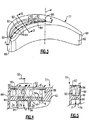
- the heat transfer augmentation devices 192 are formed on both a suction side lip 182 and a pressure side lip 184 of the tip pocket 180 and may extend radially outwardly from a floor 190 of the tip pocket 180. In other words, the heat transfer augmentation devices 192 of this arrangement extend vertically. The heat transfer augmentation devices 192 may extend to the same height as the suction side lip 182 and the pressure side lip 184, in one arrangement.
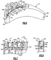
- FIGS 18 and 19 illustrate yet another tip 477 of an airfoil 462 falling outside the scope off the invention.
- a tip pocket 480 is formed at the tip 477 and includes a plurality of heat transfer augmentation devices 492.
- the heat transfer augmentation devices 492 are formed on a floor 490 of the tip pocket 480.
- the heat transfer augmentation devices 492 of this arrangement are chevrons.
- the heat transfer augmentation devices 492 may point toward a leading edge lip 486 (see Figure 19 ) or a trailing edge lip 488 (see Figure 18 ) of the tip pocket 480.
- the tip pocket 580 is disposed at a tip 577 of an airfoil 562.
- the tip pocket 580 includes a plurality of heat transfer augmentation devices 592 that are disposed at each of a floor 590, a suction side lip 582 and a pressure side lip 584 of the tip pocket 580.
Landscapes
- Engineering & Computer Science (AREA)
- Mechanical Engineering (AREA)
- General Engineering & Computer Science (AREA)
- Architecture (AREA)
- Turbine Rotor Nozzle Sealing (AREA)
Claims (13)
- Bauteil eines Gasturbinentriebwerks, umfassend:ein Schaufelprofil (662), das eine Druckseitenwand (70) und eine Saugseitenwand (72) beinhaltet, die sowohl an einer Vorderkante (66) als auch an einer Hinterkante (68) aufeinandertreffen, wobei sich das Schaufelprofil zu einer Spitze (677) erstreckt;eine Spitzenvertiefung (680), die in der Spitze (677) ausgebildet ist und die vor der Hinterkante (68) endet; undeine Vorrichtung (692) zur Verstärkung der Wärmeübertragung, die in der Spitzenvertiefung (680) ausgebildet ist; wobei die Spitzenvertiefung (680) nahe einer Profilhöhenmitte des Schaufelprofils (662) relativ zur Vorder- und zur Hinterkante (66, 68) endet, und wobei die Vorrichtung zur Verstärkung der Wärmeübertragung eine Rampe (692) beinhaltet, dadurch gekennzeichnet, dass:die Rampe (692) einen Boden (690) der Spitzenvertiefung (680) in radial versetzte Bodenabschnitte (693, 695) aufteilt; unddas Bauteil ferner eine Vielzahl von Kühllöchern umfasst, die die Spitzenvertiefung (680) fluidmäßig mit mindestens einem inneren Kühlhohlraum verbinden, der innerhalb des Schaufelprofils (680) ausgebildet ist.
- Bauteil nach Anspruch 1, wobei die Spitzenvertiefung (680) eine Saugseitenlippe (682), eine Druckseitenlippe (684), eine Vorderkantenlippe und eine Hinterkantenlippe beinhaltet, die sich von einem Boden (690) radial nach außen erstrecken.
- Bauteil nach Anspruch 2, wobei sich die Vorrichtung (92) zur Verstärkung der Wärmeübertragung axial über mindestens eine aus der Saugseitenlippe (82) und der Druckseitenlippe (84) erstreckt, wobei sich die Vorrichtung zur Verstärkung der Wärmeübertragung optional von der Vorderkantenlippe (82) zur Hinterkantenlippe (84) erstreckt.
- Bauteil nach Anspruch 2, wobei sich die Vorrichtung (192; 292) zur Verstärkung der Wärmeübertragung von dem Boden (190; 290) über mindestens eine aus der Saugseitenlippe (184; 284) und der Druckseitenlippe (184; 284) radial nach außen erstreckt.
- Bauteil nach Anspruch 4, wobei die Vorrichtung zur Verstärkung der Wärmeübertragung entweder zur Vorderkantenlippe (186; 286) oder zur Hinterkantenlippe (188; 288) hin abgeschrägt ist.
- Bauteil nach Anspruch 2, wobei die Vorrichtung (392; 492; 592; 692) zur Verstärkung der Wärmeübertragung auf dem Boden (390; 490; 590; 690) ausgebildet ist und sich zwischen der Saugseitenlippe (382; 482; 582; 682) und der Druckseitenlippe (384; 484; 584; 684) erstreckt, wobei, optional, die Vorrichtung (392) zur Verstärkung der Wärmeübertragung spitz zuläuft.
- Bauteil nach Anspruch 1 oder 2, wobei die Vorrichtung (492) zur Verstärkung der Wärmeübertragung eine Zickzackleiste oder ein Stolperstreifen ist.
- Bauteil nach Anspruch 1 oder 2, wobei die Vorrichtung (592) zur Verstärkung der Wärmeübertragung auf einer Saugseitenlippe (582) der Spitzenvertiefung (580) ausgebildet ist und eine zweite Vorrichtung (592) zur Verstärkung der Wärmeübertragung auf einer Druckseitenlippe (584) der Spitzenvertiefung (580) ausgebildet ist, und, optional, eine dritte Vorrichtung (592) zur Verstärkung der Wärmeübertragung umfassend, die auf einem Boden (590) der Spitzenvertiefung (580) ausgebildet ist.
- Bauteil nach Anspruch 1 oder 2, wobei die Vorrichtung (292) zur Verstärkung der Wärmeübertragung in einem Winkel relativ zu einem oder dem Boden (290) der Spitzenvertiefung (280) abgeschrägt ist.
- Bauteil nach Anspruch 9, wobei die eine oder Vielzahl von Kühllöchern (94...794) relativ zu einer Mittelachse der Spitzenvertiefung (80...780) angeordnet sind, und eine Wand der Vorrichtung (194; 294) zur Verstärkung der Wärmeübertragung endet, bevor sie die Mittelachse schneidet.
- Bauteil nach Anspruch 10, wobei mindestens eines aus einer oder der Vielzahl von Kühllöchern (94...794) relativ zu einem oder dem Boden (90...790) der Spitzenvertiefung (80...780) abgewinkelt ist.
- Gasturbinentriebwerk, umfassend:ein Bauteil eines Gasturbinentriebwerks nach einem der vorstehenden Ansprüche.
- Verfahren zum Kühlen eins Bauteils eines Gasturbinentriebwerks, umfassend:Leiten eines Kühlfluids in eine Spitzenvertiefung (680), die an einer Spitze (670) eines Schaufelprofils (662) ausgebildet ist, wobei die Spitzenvertiefung (680) vor einer Hinterkante des Bauteils (662) nahe einer Profilhöhenmitte (M) des Schaufelprofils endet;vorübergehendes Blockieren des Kühlfluids innerhalb der Spitzenvertiefung (680) mit mindestens einer Vorrichtung (692) zur Verstärkung der Wärmeübertragung, wobei die Vorrichtung (692) zur Verstärkung der Wärme eine Rampe (692) beinhaltet, die einen Boden (690) der Spitzenvertiefung (680) in radial versetzte Bodenabschnitte (693, 695) aufteilt, wobei Kühllöcher die Spitzenvertiefung (680) fluidmäßig mit mindestens einem inneren Kühlhohlraum verbinden, der im Inneren des Schaufelprofils (680) ausgebildet ist; undAusstoßen des Kühlfluids aus der Spitzenvertiefung (680) in einen Gasstrom.
Applications Claiming Priority (1)
| Application Number | Priority Date | Filing Date | Title |
|---|---|---|---|
| US201461994270P | 2014-05-16 | 2014-05-16 |
Publications (3)
| Publication Number | Publication Date |
|---|---|
| EP2944764A1 EP2944764A1 (de) | 2015-11-18 |
| EP2944764A8 EP2944764A8 (de) | 2017-06-07 |
| EP2944764B1 true EP2944764B1 (de) | 2021-04-28 |
Family
ID=53180497
Family Applications (1)
| Application Number | Title | Priority Date | Filing Date |
|---|---|---|---|
| EP15001485.0A Active EP2944764B1 (de) | 2014-05-16 | 2015-05-18 | Bauteil eines gasturbinentriebwerks, zugehöriges gasturbinentriebwerk und kühlverfahren |
Country Status (2)
| Country | Link |
|---|---|
| US (4) | US10012089B2 (de) |
| EP (1) | EP2944764B1 (de) |
Families Citing this family (19)
| Publication number | Priority date | Publication date | Assignee | Title |
|---|---|---|---|---|
| US20150345301A1 (en) * | 2014-05-29 | 2015-12-03 | General Electric Company | Rotor blade cooling flow |
| US10053992B2 (en) | 2015-07-02 | 2018-08-21 | United Technologies Corporation | Gas turbine engine airfoil squealer pocket cooling hole configuration |
| US20170022823A1 (en) * | 2015-07-23 | 2017-01-26 | United Technologies Corporation | Turbine rotors including turbine blades having turbulator-cooled tip pockets |
| JP6565105B2 (ja) * | 2015-09-29 | 2019-08-28 | 三菱日立パワーシステムズ株式会社 | 動翼及びこれを備えるガスタービン |
| WO2017146680A1 (en) * | 2016-02-23 | 2017-08-31 | Siemens Aktiengesellschaft | Turbine blade squealer tip with vortex disrupting fence |
| US10801331B2 (en) * | 2016-06-07 | 2020-10-13 | Raytheon Technologies Corporation | Gas turbine engine rotor including squealer tip pocket |
| US10400608B2 (en) * | 2016-11-23 | 2019-09-03 | General Electric Company | Cooling structure for a turbine component |
| US11021967B2 (en) * | 2017-04-03 | 2021-06-01 | General Electric Company | Turbine engine component with a core tie hole |
| US20190003316A1 (en) * | 2017-06-29 | 2019-01-03 | United Technologies Corporation | Helical skin cooling passages for turbine airfoils |
| KR101985093B1 (ko) * | 2017-09-12 | 2019-05-31 | 두산중공업 주식회사 | 블레이드 팁의 실링구조와 이를 포함하는 가스터빈 |
| KR20190127024A (ko) * | 2018-05-03 | 2019-11-13 | 두산중공업 주식회사 | 터빈 블레이드 및 상기 터빈 블레이드를 포함하는 가스 터빈 |
| US20190368359A1 (en) * | 2018-06-05 | 2019-12-05 | United Technologies Corporation | Squealer shelf airfoil tip |
| US10961854B2 (en) * | 2018-09-12 | 2021-03-30 | Raytheon Technologies Corporation | Dirt funnel squealer purges |
| US11118462B2 (en) * | 2019-01-24 | 2021-09-14 | Pratt & Whitney Canada Corp. | Blade tip pocket rib |
| CN110566284A (zh) * | 2019-10-09 | 2019-12-13 | 西北工业大学 | 一种带阻隔肋的凹槽叶顶结构 |
| US11371359B2 (en) * | 2020-11-26 | 2022-06-28 | Pratt & Whitney Canada Corp. | Turbine blade for a gas turbine engine |
| CN112922674B (zh) * | 2021-02-04 | 2022-07-26 | 南京航空航天大学 | 一种具有气膜冷却凹槽的涡轮叶片 |
| US11659043B1 (en) | 2022-01-27 | 2023-05-23 | Meta Platforms Technologies, Llc | Systems and methods for predictively downloading volumetric data |
| EP4311914B1 (de) * | 2022-07-26 | 2025-05-07 | Siemens Energy Global GmbH & Co. KG | Turbinenlaufschaufel |
Family Cites Families (18)
| Publication number | Priority date | Publication date | Assignee | Title |
|---|---|---|---|---|
| DE19963375A1 (de) | 1999-12-28 | 2001-07-12 | Abb Alstom Power Ch Ag | Schaufel für den Rotor einer Gasturbine sowie Gasturbine mit einer solchen Schaufel |
| US7739162B1 (en) * | 2001-05-04 | 2010-06-15 | West Corporation | System, method, and business method for setting micropayment transaction to a pre-paid instrument |
| US20030021684A1 (en) | 2001-07-24 | 2003-01-30 | Downs James P. | Turbine blade tip cooling construction |
| US7537431B1 (en) | 2006-08-21 | 2009-05-26 | Florida Turbine Technologies, Inc. | Turbine blade tip with mini-serpentine cooling circuit |
| US8512003B2 (en) * | 2006-08-21 | 2013-08-20 | General Electric Company | Tip ramp turbine blade |
| US8011889B1 (en) | 2007-09-07 | 2011-09-06 | Florida Turbine Technologies, Inc. | Turbine blade with trailing edge tip corner cooling |
| FR2934008B1 (fr) | 2008-07-21 | 2015-06-05 | Turbomeca | Aube creuse de roue de turbine comportant une nervure |
| CN102057134B (zh) | 2008-10-30 | 2015-04-22 | 三菱日立电力系统株式会社 | 具有削薄接片的涡轮动叶片 |
| US8435004B1 (en) | 2010-04-13 | 2013-05-07 | Florida Turbine Technologies, Inc. | Turbine blade with tip rail cooling |
| US8690536B2 (en) | 2010-09-28 | 2014-04-08 | Siemens Energy, Inc. | Turbine blade tip with vortex generators |
| US9228442B2 (en) | 2012-04-05 | 2016-01-05 | United Technologies Corporation | Turbine airfoil tip shelf and squealer pocket cooling |
| EP2666968B1 (de) | 2012-05-24 | 2021-08-18 | General Electric Company | Turbinenlaufschaufel |
| US9188012B2 (en) * | 2012-05-24 | 2015-11-17 | General Electric Company | Cooling structures in the tips of turbine rotor blades |
| US9470096B2 (en) | 2012-07-26 | 2016-10-18 | General Electric Company | Turbine bucket with notched squealer tip |
| US9045988B2 (en) | 2012-07-26 | 2015-06-02 | General Electric Company | Turbine bucket with squealer tip |
| US10408066B2 (en) | 2012-08-15 | 2019-09-10 | United Technologies Corporation | Suction side turbine blade tip cooling |
| JP6168746B2 (ja) * | 2012-10-10 | 2017-07-26 | キヤノン株式会社 | スイッチング電源及びスイッチング電源を備えた画像形成装置 |
| US10436039B2 (en) | 2013-11-11 | 2019-10-08 | United Technologies Corporation | Gas turbine engine turbine blade tip cooling |
-
2015
- 2015-05-05 US US14/704,022 patent/US10012089B2/en active Active
- 2015-05-18 EP EP15001485.0A patent/EP2944764B1/de active Active
-
2018
- 2018-06-01 US US15/995,884 patent/US10633981B2/en active Active
-
2020
- 2020-04-27 US US16/858,955 patent/US11156101B2/en active Active
-
2021
- 2021-09-23 US US17/482,478 patent/US11661853B2/en active Active
Non-Patent Citations (1)
| Title |
|---|
| None * |
Also Published As
| Publication number | Publication date |
|---|---|
| US11156101B2 (en) | 2021-10-26 |
| US20200291793A1 (en) | 2020-09-17 |
| US20150330228A1 (en) | 2015-11-19 |
| US10012089B2 (en) | 2018-07-03 |
| US11661853B2 (en) | 2023-05-30 |
| US20180274373A1 (en) | 2018-09-27 |
| EP2944764A1 (de) | 2015-11-18 |
| US20220003120A1 (en) | 2022-01-06 |
| US10633981B2 (en) | 2020-04-28 |
| EP2944764A8 (de) | 2017-06-07 |
Similar Documents
| Publication | Publication Date | Title |
|---|---|---|
| US11661853B2 (en) | Airfoil tip pocket with augmentation features | |
| EP2942488B1 (de) | Laufschaufel für ein gasturbinentriebwerk, gasturbinentriebwerk und verfahren zur kühlung einer laufschaufel für ein gasturbinentriebwerk | |
| EP3043027B1 (de) | Gasturbinenmotorkomponente mit konformem kehlkühlungspfad | |
| US10253634B2 (en) | Gas turbine engine airfoil trailing edge suction side cooling | |
| EP2944761B1 (de) | Gasturbinenmotorkomponente mit plattformkühlung | |
| EP3084136B1 (de) | Laufschaufel und zugehöriges verfahren zur kühlung einer plattform einer laufschaufel | |
| EP3042041B1 (de) | Gasturbinenmotorflügelturbulator für flügelkriechbeständigkeit | |
| EP2993304B1 (de) | Gasturbinenmotorkomponente mit filmkühlungsloch | |
| EP3009616A1 (de) | Gasturbinenbauteil mit plattformkühlung | |
| EP3179040A1 (de) | Bauteil für ein gasturbinentriebwerk und zugehöriges verfahren zur herstellung eines filmgekühltes artikels | |
| EP3112596A1 (de) | Gasturbinenmotorschaufel mit biaxialem wandkühlkanal und zugehöriger gasturbinenmotor | |
| EP3009600A1 (de) | Turbinenschaufel mit spitzenkühlung eines gasturbinentriebwerks | |
| EP3054093B1 (de) | Anordnung von turbulatoren | |
| EP3051066B1 (de) | Gusskern mit versetzten fortsätzen | |
| US11149548B2 (en) | Method of reducing manufacturing variation related to blocked cooling holes | |
| US20160194969A1 (en) | Turbine Vane With Platform Rib | |
| WO2015047576A1 (en) | Diffused platform cooling holes | |
| EP3581762B1 (de) | Kühlkanalanordnung für gasturbinendeckband | |
| EP2975222A1 (de) | Gekühlte tasche in einer turbinenschaufelplattform | |
| EP2942486A1 (de) | Konfiguration des kühlkanals einer gasturbinenmotorschaufel |
Legal Events
| Date | Code | Title | Description |
|---|---|---|---|
| PUAI | Public reference made under article 153(3) epc to a published international application that has entered the european phase |
Free format text: ORIGINAL CODE: 0009012 |
|
| AK | Designated contracting states |
Kind code of ref document: A1 Designated state(s): AL AT BE BG CH CY CZ DE DK EE ES FI FR GB GR HR HU IE IS IT LI LT LU LV MC MK MT NL NO PL PT RO RS SE SI SK SM TR |
|
| AX | Request for extension of the european patent |
Extension state: BA ME |
|
| RIN1 | Information on inventor provided before grant (corrected) |
Inventor name: GAUTSCHI, STEVEN BRUCE Inventor name: PROPHETER-HINCKLEY, TRACY A. Inventor name: QUACH, SAN |
|
| 17P | Request for examination filed |
Effective date: 20160517 |
|
| RBV | Designated contracting states (corrected) |
Designated state(s): AL AT BE BG CH CY CZ DE DK EE ES FI FR GB GR HR HU IE IS IT LI LT LU LV MC MK MT NL NO PL PT RO RS SE SI SK SM TR |
|
| RIN1 | Information on inventor provided before grant (corrected) |
Inventor name: PROPHETER-HINCKLEY, TRACY A. Inventor name: QUACH, SAN Inventor name: GAUTSCHI, STEVEN BRUCE |
|
| RAP1 | Party data changed (applicant data changed or rights of an application transferred) |
Owner name: UNITED TECHNOLOGIES CORPORATION |
|
| RIC1 | Information provided on ipc code assigned before grant |
Ipc: F01D 5/20 20060101AFI20200212BHEP |
|
| GRAP | Despatch of communication of intention to grant a patent |
Free format text: ORIGINAL CODE: EPIDOSNIGR1 |
|
| STAA | Information on the status of an ep patent application or granted ep patent |
Free format text: STATUS: GRANT OF PATENT IS INTENDED |
|
| INTG | Intention to grant announced |
Effective date: 20200604 |
|
| RIN1 | Information on inventor provided before grant (corrected) |
Inventor name: GAUTSCHI, STEVEN BRUCE Inventor name: PROPHETER-HINCKLEY, TRACY A. Inventor name: QUACH, SAN |
|
| GRAJ | Information related to disapproval of communication of intention to grant by the applicant or resumption of examination proceedings by the epo deleted |
Free format text: ORIGINAL CODE: EPIDOSDIGR1 |
|
| STAA | Information on the status of an ep patent application or granted ep patent |
Free format text: STATUS: REQUEST FOR EXAMINATION WAS MADE |
|
| GRAP | Despatch of communication of intention to grant a patent |
Free format text: ORIGINAL CODE: EPIDOSNIGR1 |
|
| STAA | Information on the status of an ep patent application or granted ep patent |
Free format text: STATUS: GRANT OF PATENT IS INTENDED |
|
| INTC | Intention to grant announced (deleted) | ||
| INTG | Intention to grant announced |
Effective date: 20201113 |
|
| GRAS | Grant fee paid |
Free format text: ORIGINAL CODE: EPIDOSNIGR3 |
|
| RAP1 | Party data changed (applicant data changed or rights of an application transferred) |
Owner name: RAYTHEON TECHNOLOGIES CORPORATION |
|
| GRAA | (expected) grant |
Free format text: ORIGINAL CODE: 0009210 |
|
| STAA | Information on the status of an ep patent application or granted ep patent |
Free format text: STATUS: THE PATENT HAS BEEN GRANTED |
|
| AK | Designated contracting states |
Kind code of ref document: B1 Designated state(s): AL AT BE BG CH CY CZ DE DK EE ES FI FR GB GR HR HU IE IS IT LI LT LU LV MC MK MT NL NO PL PT RO RS SE SI SK SM TR |
|
| REG | Reference to a national code |
Ref country code: GB Ref legal event code: FG4D |
|
| REG | Reference to a national code |
Ref country code: CH Ref legal event code: EP |
|
| REG | Reference to a national code |
Ref country code: DE Ref legal event code: R096 Ref document number: 602015068549 Country of ref document: DE |
|
| REG | Reference to a national code |
Ref country code: AT Ref legal event code: REF Ref document number: 1387254 Country of ref document: AT Kind code of ref document: T Effective date: 20210515 |
|
| REG | Reference to a national code |
Ref country code: IE Ref legal event code: FG4D |
|
| REG | Reference to a national code |
Ref country code: LT Ref legal event code: MG9D |
|
| REG | Reference to a national code |
Ref country code: AT Ref legal event code: MK05 Ref document number: 1387254 Country of ref document: AT Kind code of ref document: T Effective date: 20210428 |
|
| PG25 | Lapsed in a contracting state [announced via postgrant information from national office to epo] |
Ref country code: FI Free format text: LAPSE BECAUSE OF FAILURE TO SUBMIT A TRANSLATION OF THE DESCRIPTION OR TO PAY THE FEE WITHIN THE PRESCRIBED TIME-LIMIT Effective date: 20210428 Ref country code: NL Free format text: LAPSE BECAUSE OF FAILURE TO SUBMIT A TRANSLATION OF THE DESCRIPTION OR TO PAY THE FEE WITHIN THE PRESCRIBED TIME-LIMIT Effective date: 20210428 Ref country code: LT Free format text: LAPSE BECAUSE OF FAILURE TO SUBMIT A TRANSLATION OF THE DESCRIPTION OR TO PAY THE FEE WITHIN THE PRESCRIBED TIME-LIMIT Effective date: 20210428 Ref country code: AT Free format text: LAPSE BECAUSE OF FAILURE TO SUBMIT A TRANSLATION OF THE DESCRIPTION OR TO PAY THE FEE WITHIN THE PRESCRIBED TIME-LIMIT Effective date: 20210428 Ref country code: BG Free format text: LAPSE BECAUSE OF FAILURE TO SUBMIT A TRANSLATION OF THE DESCRIPTION OR TO PAY THE FEE WITHIN THE PRESCRIBED TIME-LIMIT Effective date: 20210728 Ref country code: HR Free format text: LAPSE BECAUSE OF FAILURE TO SUBMIT A TRANSLATION OF THE DESCRIPTION OR TO PAY THE FEE WITHIN THE PRESCRIBED TIME-LIMIT Effective date: 20210428 |
|
| PG25 | Lapsed in a contracting state [announced via postgrant information from national office to epo] |
Ref country code: LV Free format text: LAPSE BECAUSE OF FAILURE TO SUBMIT A TRANSLATION OF THE DESCRIPTION OR TO PAY THE FEE WITHIN THE PRESCRIBED TIME-LIMIT Effective date: 20210428 Ref country code: IS Free format text: LAPSE BECAUSE OF FAILURE TO SUBMIT A TRANSLATION OF THE DESCRIPTION OR TO PAY THE FEE WITHIN THE PRESCRIBED TIME-LIMIT Effective date: 20210828 Ref country code: GR Free format text: LAPSE BECAUSE OF FAILURE TO SUBMIT A TRANSLATION OF THE DESCRIPTION OR TO PAY THE FEE WITHIN THE PRESCRIBED TIME-LIMIT Effective date: 20210729 Ref country code: ES Free format text: LAPSE BECAUSE OF FAILURE TO SUBMIT A TRANSLATION OF THE DESCRIPTION OR TO PAY THE FEE WITHIN THE PRESCRIBED TIME-LIMIT Effective date: 20210428 Ref country code: PT Free format text: LAPSE BECAUSE OF FAILURE TO SUBMIT A TRANSLATION OF THE DESCRIPTION OR TO PAY THE FEE WITHIN THE PRESCRIBED TIME-LIMIT Effective date: 20210830 Ref country code: PL Free format text: LAPSE BECAUSE OF FAILURE TO SUBMIT A TRANSLATION OF THE DESCRIPTION OR TO PAY THE FEE WITHIN THE PRESCRIBED TIME-LIMIT Effective date: 20210428 Ref country code: NO Free format text: LAPSE BECAUSE OF FAILURE TO SUBMIT A TRANSLATION OF THE DESCRIPTION OR TO PAY THE FEE WITHIN THE PRESCRIBED TIME-LIMIT Effective date: 20210728 Ref country code: RS Free format text: LAPSE BECAUSE OF FAILURE TO SUBMIT A TRANSLATION OF THE DESCRIPTION OR TO PAY THE FEE WITHIN THE PRESCRIBED TIME-LIMIT Effective date: 20210428 Ref country code: SE Free format text: LAPSE BECAUSE OF FAILURE TO SUBMIT A TRANSLATION OF THE DESCRIPTION OR TO PAY THE FEE WITHIN THE PRESCRIBED TIME-LIMIT Effective date: 20210428 |
|
| REG | Reference to a national code |
Ref country code: NL Ref legal event code: MP Effective date: 20210428 |
|
| REG | Reference to a national code |
Ref country code: CH Ref legal event code: PL |
|
| PG25 | Lapsed in a contracting state [announced via postgrant information from national office to epo] |
Ref country code: RO Free format text: LAPSE BECAUSE OF FAILURE TO SUBMIT A TRANSLATION OF THE DESCRIPTION OR TO PAY THE FEE WITHIN THE PRESCRIBED TIME-LIMIT Effective date: 20210428 Ref country code: LI Free format text: LAPSE BECAUSE OF NON-PAYMENT OF DUE FEES Effective date: 20210531 Ref country code: LU Free format text: LAPSE BECAUSE OF NON-PAYMENT OF DUE FEES Effective date: 20210518 Ref country code: MC Free format text: LAPSE BECAUSE OF FAILURE TO SUBMIT A TRANSLATION OF THE DESCRIPTION OR TO PAY THE FEE WITHIN THE PRESCRIBED TIME-LIMIT Effective date: 20210428 Ref country code: CH Free format text: LAPSE BECAUSE OF NON-PAYMENT OF DUE FEES Effective date: 20210531 Ref country code: CZ Free format text: LAPSE BECAUSE OF FAILURE TO SUBMIT A TRANSLATION OF THE DESCRIPTION OR TO PAY THE FEE WITHIN THE PRESCRIBED TIME-LIMIT Effective date: 20210428 Ref country code: DK Free format text: LAPSE BECAUSE OF FAILURE TO SUBMIT A TRANSLATION OF THE DESCRIPTION OR TO PAY THE FEE WITHIN THE PRESCRIBED TIME-LIMIT Effective date: 20210428 Ref country code: EE Free format text: LAPSE BECAUSE OF FAILURE TO SUBMIT A TRANSLATION OF THE DESCRIPTION OR TO PAY THE FEE WITHIN THE PRESCRIBED TIME-LIMIT Effective date: 20210428 Ref country code: SK Free format text: LAPSE BECAUSE OF FAILURE TO SUBMIT A TRANSLATION OF THE DESCRIPTION OR TO PAY THE FEE WITHIN THE PRESCRIBED TIME-LIMIT Effective date: 20210428 Ref country code: SM Free format text: LAPSE BECAUSE OF FAILURE TO SUBMIT A TRANSLATION OF THE DESCRIPTION OR TO PAY THE FEE WITHIN THE PRESCRIBED TIME-LIMIT Effective date: 20210428 |
|
| REG | Reference to a national code |
Ref country code: DE Ref legal event code: R097 Ref document number: 602015068549 Country of ref document: DE |
|
| REG | Reference to a national code |
Ref country code: BE Ref legal event code: MM Effective date: 20210531 |
|
| PLBE | No opposition filed within time limit |
Free format text: ORIGINAL CODE: 0009261 |
|
| STAA | Information on the status of an ep patent application or granted ep patent |
Free format text: STATUS: NO OPPOSITION FILED WITHIN TIME LIMIT |
|
| 26N | No opposition filed |
Effective date: 20220131 |
|
| PG25 | Lapsed in a contracting state [announced via postgrant information from national office to epo] |
Ref country code: IE Free format text: LAPSE BECAUSE OF NON-PAYMENT OF DUE FEES Effective date: 20210518 |
|
| PG25 | Lapsed in a contracting state [announced via postgrant information from national office to epo] |
Ref country code: IS Free format text: LAPSE BECAUSE OF FAILURE TO SUBMIT A TRANSLATION OF THE DESCRIPTION OR TO PAY THE FEE WITHIN THE PRESCRIBED TIME-LIMIT Effective date: 20210828 Ref country code: AL Free format text: LAPSE BECAUSE OF FAILURE TO SUBMIT A TRANSLATION OF THE DESCRIPTION OR TO PAY THE FEE WITHIN THE PRESCRIBED TIME-LIMIT Effective date: 20210428 |
|
| PG25 | Lapsed in a contracting state [announced via postgrant information from national office to epo] |
Ref country code: IT Free format text: LAPSE BECAUSE OF FAILURE TO SUBMIT A TRANSLATION OF THE DESCRIPTION OR TO PAY THE FEE WITHIN THE PRESCRIBED TIME-LIMIT Effective date: 20210428 Ref country code: BE Free format text: LAPSE BECAUSE OF NON-PAYMENT OF DUE FEES Effective date: 20210531 |
|
| PG25 | Lapsed in a contracting state [announced via postgrant information from national office to epo] |
Ref country code: HU Free format text: LAPSE BECAUSE OF FAILURE TO SUBMIT A TRANSLATION OF THE DESCRIPTION OR TO PAY THE FEE WITHIN THE PRESCRIBED TIME-LIMIT; INVALID AB INITIO Effective date: 20150518 |
|
| P01 | Opt-out of the competence of the unified patent court (upc) registered |
Effective date: 20230520 |
|
| PG25 | Lapsed in a contracting state [announced via postgrant information from national office to epo] |
Ref country code: CY Free format text: LAPSE BECAUSE OF FAILURE TO SUBMIT A TRANSLATION OF THE DESCRIPTION OR TO PAY THE FEE WITHIN THE PRESCRIBED TIME-LIMIT Effective date: 20210428 |
|
| PG25 | Lapsed in a contracting state [announced via postgrant information from national office to epo] |
Ref country code: MK Free format text: LAPSE BECAUSE OF FAILURE TO SUBMIT A TRANSLATION OF THE DESCRIPTION OR TO PAY THE FEE WITHIN THE PRESCRIBED TIME-LIMIT Effective date: 20210428 |
|
| PG25 | Lapsed in a contracting state [announced via postgrant information from national office to epo] |
Ref country code: MT Free format text: LAPSE BECAUSE OF FAILURE TO SUBMIT A TRANSLATION OF THE DESCRIPTION OR TO PAY THE FEE WITHIN THE PRESCRIBED TIME-LIMIT Effective date: 20210428 |
|
| PGFP | Annual fee paid to national office [announced via postgrant information from national office to epo] |
Ref country code: DE Payment date: 20250423 Year of fee payment: 11 |
|
| PGFP | Annual fee paid to national office [announced via postgrant information from national office to epo] |
Ref country code: GB Payment date: 20250423 Year of fee payment: 11 |
|
| PGFP | Annual fee paid to national office [announced via postgrant information from national office to epo] |
Ref country code: FR Payment date: 20250424 Year of fee payment: 11 |
|
| REG | Reference to a national code |
Ref country code: DE Ref legal event code: R081 Ref document number: 602015068549 Country of ref document: DE Owner name: RTX CORPORATION (N.D.GES.D. STAATES DELAWARE),, US Free format text: FORMER OWNER: RAYTHEON TECHNOLOGIES CORPORATION, FARMINGTON, CT, US |
|
| PG25 | Lapsed in a contracting state [announced via postgrant information from national office to epo] |
Ref country code: TR Free format text: LAPSE BECAUSE OF FAILURE TO SUBMIT A TRANSLATION OF THE DESCRIPTION OR TO PAY THE FEE WITHIN THE PRESCRIBED TIME-LIMIT Effective date: 20210428 |