EP2944768B1 - Dispositif distributeur pour refroidir l'air à l'intérieur d'un moteur - Google Patents
Dispositif distributeur pour refroidir l'air à l'intérieur d'un moteur Download PDFInfo
- Publication number
- EP2944768B1 EP2944768B1 EP15165171.8A EP15165171A EP2944768B1 EP 2944768 B1 EP2944768 B1 EP 2944768B1 EP 15165171 A EP15165171 A EP 15165171A EP 2944768 B1 EP2944768 B1 EP 2944768B1
- Authority
- EP
- European Patent Office
- Prior art keywords
- air
- deflector
- air inlet
- distributor device
- deflecting surface
- Prior art date
- Legal status (The legal status is an assumption and is not a legal conclusion. Google has not performed a legal analysis and makes no representation as to the accuracy of the status listed.)
- Not-in-force
Links
- 238000001816 cooling Methods 0.000 title claims description 89
- 238000009826 distribution Methods 0.000 claims description 30
- 239000012530 fluid Substances 0.000 claims description 9
- 238000004891 communication Methods 0.000 claims description 8
- 238000004873 anchoring Methods 0.000 claims description 3
- 239000007789 gas Substances 0.000 description 52
- 230000002093 peripheral effect Effects 0.000 description 9
- 238000003466 welding Methods 0.000 description 6
- 239000012809 cooling fluid Substances 0.000 description 5
- 238000007620 mathematical function Methods 0.000 description 5
- 238000000034 method Methods 0.000 description 5
- 230000008859 change Effects 0.000 description 3
- 230000000694 effects Effects 0.000 description 3
- 239000007788 liquid Substances 0.000 description 3
- 230000009467 reduction Effects 0.000 description 3
- 238000007514 turning Methods 0.000 description 3
- 230000006866 deterioration Effects 0.000 description 2
- 238000004519 manufacturing process Methods 0.000 description 2
- 239000000654 additive Substances 0.000 description 1
- 238000007664 blowing Methods 0.000 description 1
- 238000002485 combustion reaction Methods 0.000 description 1
- 239000000112 cooling gas Substances 0.000 description 1
- 238000005336 cracking Methods 0.000 description 1
- 238000005520 cutting process Methods 0.000 description 1
- 230000001419 dependent effect Effects 0.000 description 1
- 238000005516 engineering process Methods 0.000 description 1
- 238000009499 grossing Methods 0.000 description 1
- 238000003754 machining Methods 0.000 description 1
- 239000000463 material Substances 0.000 description 1
- 238000002156 mixing Methods 0.000 description 1
- 238000012986 modification Methods 0.000 description 1
- 230000004048 modification Effects 0.000 description 1
- 230000003071 parasitic effect Effects 0.000 description 1
- 238000005192 partition Methods 0.000 description 1
- 238000007789 sealing Methods 0.000 description 1
- 238000000926 separation method Methods 0.000 description 1
- 238000004227 thermal cracking Methods 0.000 description 1
- 238000009827 uniform distribution Methods 0.000 description 1
- 238000011144 upstream manufacturing Methods 0.000 description 1
Images




Classifications
-
- F—MECHANICAL ENGINEERING; LIGHTING; HEATING; WEAPONS; BLASTING
- F01—MACHINES OR ENGINES IN GENERAL; ENGINE PLANTS IN GENERAL; STEAM ENGINES
- F01D—NON-POSITIVE DISPLACEMENT MACHINES OR ENGINES, e.g. STEAM TURBINES
- F01D9/00—Stators
- F01D9/06—Fluid supply conduits to nozzles or the like
- F01D9/065—Fluid supply or removal conduits traversing the working fluid flow, e.g. for lubrication-, cooling-, or sealing fluids
-
- F—MECHANICAL ENGINEERING; LIGHTING; HEATING; WEAPONS; BLASTING
- F01—MACHINES OR ENGINES IN GENERAL; ENGINE PLANTS IN GENERAL; STEAM ENGINES
- F01D—NON-POSITIVE DISPLACEMENT MACHINES OR ENGINES, e.g. STEAM TURBINES
- F01D9/00—Stators
- F01D9/06—Fluid supply conduits to nozzles or the like
-
- F—MECHANICAL ENGINEERING; LIGHTING; HEATING; WEAPONS; BLASTING
- F01—MACHINES OR ENGINES IN GENERAL; ENGINE PLANTS IN GENERAL; STEAM ENGINES
- F01D—NON-POSITIVE DISPLACEMENT MACHINES OR ENGINES, e.g. STEAM TURBINES
- F01D11/00—Preventing or minimising internal leakage of working-fluid, e.g. between stages
- F01D11/08—Preventing or minimising internal leakage of working-fluid, e.g. between stages for sealing space between rotor blade tips and stator
- F01D11/14—Adjusting or regulating tip-clearance, i.e. distance between rotor-blade tips and stator casing
- F01D11/20—Actively adjusting tip-clearance
- F01D11/24—Actively adjusting tip-clearance by selectively cooling-heating stator or rotor components
-
- F—MECHANICAL ENGINEERING; LIGHTING; HEATING; WEAPONS; BLASTING
- F02—COMBUSTION ENGINES; HOT-GAS OR COMBUSTION-PRODUCT ENGINE PLANTS
- F02C—GAS-TURBINE PLANTS; AIR INTAKES FOR JET-PROPULSION PLANTS; CONTROLLING FUEL SUPPLY IN AIR-BREATHING JET-PROPULSION PLANTS
- F02C7/00—Features, components parts, details or accessories, not provided for in, or of interest apart form groups F02C1/00 - F02C6/00; Air intakes for jet-propulsion plants
- F02C7/12—Cooling of plants
- F02C7/16—Cooling of plants characterised by cooling medium
- F02C7/18—Cooling of plants characterised by cooling medium the medium being gaseous, e.g. air
-
- Y—GENERAL TAGGING OF NEW TECHNOLOGICAL DEVELOPMENTS; GENERAL TAGGING OF CROSS-SECTIONAL TECHNOLOGIES SPANNING OVER SEVERAL SECTIONS OF THE IPC; TECHNICAL SUBJECTS COVERED BY FORMER USPC CROSS-REFERENCE ART COLLECTIONS [XRACs] AND DIGESTS
- Y02—TECHNOLOGIES OR APPLICATIONS FOR MITIGATION OR ADAPTATION AGAINST CLIMATE CHANGE
- Y02T—CLIMATE CHANGE MITIGATION TECHNOLOGIES RELATED TO TRANSPORTATION
- Y02T50/00—Aeronautics or air transport
- Y02T50/60—Efficient propulsion technologies, e.g. for aircraft
Definitions
- This invention relates to a distributor device for engine cooling air. More particularly the invention relates to a distributor device for distributing and/or directing cooling air within an engine, especially a gas turbine engine.
- US5239816 describes a steam deflector assembly for a steam injected gas turbine engine having an annular manifold as a part of the combustion chamber casing.
- the manifold has a port through the exterior of the casing and a plurality of evenly spaced steam passage holes leading to the interior of the casing.
- the deflector assembly comprises an exterior bracket surrounding the port to which a steam line is attached and a deflector plate and retainer member therefor located within the manifold. The assembly protects the casing from low cycle fatigue cracking and distributes the steam flow about the manifold.
- a representative cooling air manifold splash plates includes: a base having an aperture; and an air deflector supported by the base, the air deflector being positioned relative to the base to receive, from the aperture, a radial flow of gas turbine engine cooling air, the air deflector being operative to redirect at least some of the air received circumferentially.
- US2014/013767 describes a baffle assembly for a housing of a combustor system of a gas turbine engine.
- the baffle assembly includes a baffle retainer and a baffle.
- the baffle retainer includes a retainer tube and a collar. The retainer tube is received within a bleed port of the housing. The collar is defined at an upper end of the retainer tube and is configured to rest against the housing.
- the baffle includes a baffle tube rigidly attached to an inner surface of the retainer tube.
- WO2014/105269 describes a feed diffuser which comprises a base disposed orthogonal to a flow, a body extending from the base toward the flow, and an apex provided at a termination of the body in a direction toward the flow.
- the body may decrease in cross-sectional area from the base to the apex.
- the present invention provides a distributor device according to the appended claims.
- a distributor device for distributing cooling air within a gas turbine engine may comprise:
- the term "differentially" as applied to the directing of the air from the air inlet preferably means directing the air with differing parameters of (i) direction of travel in each of a plurality of desired different, non-parallel directions, or (ii) different flow rates in each of a plurality of desired different directions, or (iii) a combination of (i) and (ii).
- the deflector of the device may comprise one or more deflecting surfaces which are curved and so configured such that air from the air inlet is directable in accordance with one or more differing parameters selected from: (i) in directions of travel in each of a plurality of desired different, non-parallel directions, or (ii) with different flow rates in a plurality of desired different directions, or (iii) a combination of (i) and (ii).
- a distributor device for distributing cooling air within a gas turbine engine comprising:
- a distributor device for distributing cooling air within a gas turbine engine comprising:
- the deflector may comprise one or more deflecting surfaces curvilinearly configured to direct the air in directions of travel in each of a plurality of desired different, non-parallel directions, the said plurality of non-parallel directions may comprise at least two orthogonal directions.
- Such orthogonal directions may for example comprise at least two orthogonal directions lying generally in or generally parallel to a plane generally substantially perpendicular to a radial direction of the gas turbine engine, which radial direction is defined as generally orthogonal to the gas turbine engine's longitudinal axis defined by the general direction of airflow through it. Further desirable and/or optional features of deflectors for use in such embodiments will be further defined and described hereinbelow.
- the deflector may comprise one or more deflecting surfaces curvilinearly configured to direct the air in each of a plurality of desired different directions with different flow rates, the said plurality of different directions may for example comprise at least two directions lying generally in or generally parallel to a plane generally substantially perpendicular to a radial direction of the gas turbine engine, which radial direction is defined as generally orthogonal to the gas turbine engine's longitudinal axis defined by the general direction of airflow through it. Further desirable and/or optional features of deflectors for use in such embodiments will be further defined and described hereinbelow.
- the distributor device may be for distributing cooling air within a gas turbine engine.
- the invention may be extended to the distribution of cooling fluids in general, including cooling gases other than air, or even cooling liquids.
- the distributor device is applicable in particular to the distribution of cooling air within a gas turbine engine, it is envisaged the device may be used in any engine that utilises a cooling fluid such as air that requires distributing therewithin, especially within a space therein, such as within a manifold thereof.
- gas turbine engines in which the device may be usefully employed may include any of: turbofan engines, turbojet engines, turboprop engines and turboshaft or electric generator engines.
- the distributor device may be employed in any part of such engines or manifolds thereof where the distribution or delivery of cooling air to particular or specific locations or regions therewithin is needed or desirable. Such locations or regions may for example be any locality or region in which an enhanced or improved level or uniformity of air delivery is wanted.
- Non-limiting examples include the delivery of cooling air to turbine vanes, or to one or more buffer air systems within a turbofan engine, such as in a HP-IP bearing hub, a tail bearing housing hub, and/or an intercase bearing.
- a manifold defining a space within a gas turbine engine for distribution therewithin of cooling air may comprise: at least one air inlet for delivering the cooling air into the space; and at least one respective distributor device.
- a manifold defining a space within a gas turbine engine for distribution therewithin of cooling air, the manifold comprising:
- a gas turbine engine comprising: a space for distribution therewithin of cooling air; at least one air inlet for delivering the cooling air into the space; and at least one respective distributor device.
- a gas turbine engine comprising:
- the gas turbine engine comprises at least one air inlet for delivering the cooling air into the space; and the or each respective air inlet has provided thereadjacent a or a respective distributor device or any embodiment thereof; wherein the method comprises: delivering air from the or each respective air inlet into the space via the or each respective distributor device, whereby the air is directed differentially in the said respective plurality of desired directions within the space.
- a deflector may be supportable by a base, the base being mountable adjacent an inlet for cooling air to be distributed within a gas turbine engine, and for fluid communication with the air inlet, the deflector being configured to direct air from the air inlet in a plurality of directions within the gas turbine engine,
- the deflector of the distributor device may comprise one or more deflecting surfaces curvilinearly configured to direct air in each of a plurality of desired different, non-parallel directions of travel.
- the said plurality of non-parallel directions may comprise at least two orthogonal directions, for example at least two orthogonal directions lying generally in or generally parallel to a plane generally substantially perpendicular to a radial direction of the gas turbine engine.
- the one or more deflecting surfaces may be curvilinearly configured such that air is directable smoothly and efficiently therefrom along a plurality of non-parallel axes preferably oriented generally substantially perpendicular to a radial direction of the gas turbine engine, which radial direction is defined as generally orthogonal to the gas turbine engine's longitudinal axis defined by the general direction of airflow through it.
- the said plurality of non-parallel axes may thus each be oriented generally substantially orthogonally to the direction in which the incoming air travels as it is delivered through the or the respective air inlet.
- the one or more curvilinearly configured deflecting surfaces of the deflector may be curved in at least two planes which are non-parallel to one another, said planes being defined as (i) each being generally parallel to the direction of air flow from the or the respective air inlet and incident on the deflecting surface(s), and (ii) being angled with respect to one another at an angle of between 0° and 180°. That is to say, the one or more curvilinearly configured deflecting surfaces of the deflector may be curved in profile when viewed in cross-section taken along at least two such different planes.
- the curved shape or profile of the deflecting surface(s) may be defined by a mathematical curve function selected from any of a circular or elliptical arc, a parabola, a hyperbola, a combination of any of the aforesaid functions, or any other suitable mathematical function.
- the curve function may be substantially constant or it may vary along the length and/or height of the deflecting surface(s).
- the deflector may comprise a substantially continuous curvilinearly configured deflecting surface extending therearound through substantially 360°.
- the deflecting surface may have a uniform curvature or curve function substantially completely through 360° therearound, whereby air is directable substantially uniformly or equally in all directions therearound.
- Such species in which the deflecting surface has a substantially uniform curvature or curve function substantially completely therearound may be particularly useful for distributing or directing air uniformly therearound, e.g. with substantially equal flow rates in all directions therearound.
- the deflecting surface may have a varying curvature or curve function at different angular positions or in different angular regions or segments therearound, whereby air is directable non-uniformly or non-equally in different directions therearound.
- the varying curvature or curve function at different angular positions or in different angular regions or segments around the deflector may be selected or tailored to direct air more favourably, e.g. with a relatively higher or lower flow rate, in certain selected one or more angular regions or segments surrounding the deflector than in other such angular regions or segments.
- a deflecting surface which has a substantially non-uniform or varying curvature or curve function therearound may be particularly useful for distributing or directing air asymmetrically therearound, e.g. with relatively higher or lower flow rates in one or more particular desired directions therearound. This may be desirable for instance in arrangements in which the gas turbine engine architecture is such that pipework or other components requiring e.g. cooling air to be directed thereto are arranged asymmetrically and so favour asymmetrical application of cooling air thereto in order to optimise the overall uniformity of the cooling effects of the distributed cooling air amongst the collective pipework or other components.
- the deflector may comprise a substantially continuous, uniformly curved deflecting surface therearound such that an air-deflecting portion of the deflector has an exterior shape corresponding to that of a bell of a trumpet.
- the base of the device may be constructed and/or arranged for mounting adjacent the or the respective air inlet.
- the base may be constructed and/or arranged for mounting on a portion of a manifold at or in or around or adjacent to which the or the respective air inlet is provided for passage of air thereinto.
- the base may be constructed and/or arranged for mounting within, e.g. centrally or concentrically within, a mouth or exit aperture of the or the respective air inlet.
- the base may itself be formed with an aperture or conduit therein for permitting passage therethrough of air from the or the respective air inlet towards and onto the deflecting surface(s) of the deflector.
- the base may comprise, or may be mounted on, a flange, e.g. an annular flange, for fixing or attachment or mounting on a portion of the gas turbine engine or manifold thereof immediately around or adjacent the or the respective air inlet.
- a flange e.g. an annular flange
- the base may comprise a tubular support, e.g. a cylindrical support, which may be fixed or attached or mounted within, e.g. centrally or concentrically within, the mouth or exit aperture of the or the respective air inlet.
- the deflector may be supported by the tubular support by virtue of being mounted thereon via one or more, preferably a plurality of, brackets, webs, ribs, vanes, struts, arms or other support elements.
- brackets, webs, ribs, vanes, struts, arms or other support elements is/are preferably configured, shaped and/or positioned such that it/they do(es) not substantially interfere with or obstruct the passage of air from the or the respective air inlet towards and onto the deflecting surface(s) of the or the respective deflector.
- the deflector may be supported by the tubular support via one or more, preferably a plurality of, brackets, webs, ribs, vanes, struts, arms or other discrete support elements, those brackets, webs, ribs, vanes, struts, arms or other discrete support elements may be substantially equiangularly positioned around the deflector.
- the deflector may be supported by the tubular support via one or more, preferably a plurality of, brackets, webs, ribs, vanes, struts, arms or other discrete support elements, the deflector may conveniently comprise a central or axial spine constituting an anchoring portion onto which the plurality of support elements are mounted or attached, and from which the deflecting surface(s) of the deflector extend(s) with a gap between the said deflecting surface(s) and the tubular support for allowing passage therethrough of air undergoing distribution or directing having impinged on the or the deflecting surface(s).
- the one or more brackets, webs, ribs, vanes, struts, arms or other discrete support elements may be substantially uniformly aligned with each other and all generally substantially parallel to the direction of flow of air from the air inlet towards and onto the deflecting surface(s) of the deflector.
- the one or more brackets, webs, ribs, vanes, struts, arms or other discrete support elements may each have a helical configuration, preferably with each helical support element being substantially parallel to its one or more immediately adjacent helical support elements(s). In this manner a degree of twisting or helical motion may be imparted to the air as it flows across and/or past the support elements in its passage from the or the respective air inlet towards and onto the deflecting surface(s) of the deflector.
- the base may comprise a tubular support, e.g. a cylindrical support, which may be fixed or attached or mounted within, e.g. centrally or concentrically within, the mouth or exit aperture of the or the respective air inlet.
- the deflector may be supported by the tubular support by virtue of being mounted thereon via its peripheral edges or edge portions via one or more, preferably a plurality of, discrete peripheral struts, arms, brackets or other support elements. Any such discrete peripheral struts, arms brackets or other support elements is/are preferably configured, shaped and/or positioned such that it/they do(es) not substantially interfere with or obstruct the passage of air from the or the respective air inlet towards and onto the deflecting surface(s) of the deflector.
- the deflector may be supported by the tubular support via one or more, preferably a plurality of, discrete peripheral struts, arms, brackets or other discrete support elements, those struts, arms, brackets or other discrete support elements may be substantially equiangularly positioned around the deflector.
- the said one or more, preferably a plurality of, discrete peripheral struts, arms, brackets or other discrete support elements may be substantially uniformly aligned with each other and all generally substantially parallel to the direction of flow of air from the or the respective air inlet towards and onto the deflecting surface(s) of the deflector.
- the deflector may be supported by the tubular support via one or more, preferably a plurality of, discrete peripheral struts, arms, brackets or other discrete support elements, the deflector may conveniently comprise a peripheral land or annular rim or flange constituting an anchoring portion onto which the plurality of discrete peripheral support elements are mounted or attached.
- the respective discrete peripheral support elements may advantageously be separated by, or the material they are formed from may have formed therein, a plurality of apertures or windows which allow passage therethrough of air undergoing distribution or directing having impinged on the deflecting surface(s).
- the deflector may be supported peripherally on the base, it may be that the deflector possesses no central or axial spine, and as a consequence it may conveniently be that the deflecting surface(s) of the deflector is/are spaced from the base with a gap therebetween, via which gap air passes from the or the respective air inlet towards and onto the deflecting surface(s) of the deflector.
- the deflecting surface of the deflector may have a substantially uniform curvature or curve function substantially completely therearound may be particularly useful for distributing or directing air uniformly therearound, e.g. with substantially equal flow rates in all directions therearound.
- the deflector of the distributor device may comprise one or more deflecting surfaces curvilinearly configured to direct air with different flow rates in a plurality of desired different directions.
- the said plurality of desired different directions may comprise any two or more directions, including both non-parallel and parallel directions.
- Such two or more directions may lie generally in or generally parallel to a plane generally substantially perpendicular to a radial direction of the gas turbine engine, which radial direction is defined as generally orthogonal to the gas turbine engine's longitudinal axis defined by the general direction of airflow through it.
- such two or more directions may be oriented at any desired angle(s) relative to each other, depending on the relative orientations of the airflows to be distributed by the deflecting surface(s) of the deflector.
- the said two or more directions may each be oriented generally substantially orthogonally to the direction in which the incoming air travels as it is delivered through the or the respective air inlet.
- the deflector may comprise a plurality of deflecting surfaces each curvilinearly configured to direct air in a respective one of the said different directions with a respective different flow rate.
- each respective deflecting surface may have its own unique curvature, which may for example be different from the curvature(s) of the other, or at least some of the other, deflecting surface(s).
- a first deflecting surface may have a first curvature and a second deflecting surface may have a second curvature, the second curvature being different from the first curvature.
- any third or subsequent deflecting surface may have a third or subsequent curvature, at least one of the third or subsequent curvatures being different from at least one or more of the first, second or other curvatures.
- the respective deflecting surfaces may each be positioned asymmetrically or offset with respect to the or the respective air inlet.
- the respective deflecting surfaces may be carried on a spine which is mounted asymmetrically or offset within or with respect to the or the respective air inlet, whereby airflow passing through the device is split asymmetrically into a plurality of discrete airflow sections, each with a different cross-sectional area and/or flow rate.
- the respective deflecting surfaces - or the spine carrying them - may for example be positioned in a chordal spatial position relative to the air inlet passageway.
- each respective deflecting surface may be selected or designed such that it is curvilinearly configured such that air is directed smoothly and efficiently therefrom in the respective desired direction at the respective desired flow rate characteristic of that respective deflecting surface.
- At least some of, and possibly all of, said plurality of desired different directions may each be along one of a plurality of axes preferably oriented generally substantially perpendicular to the radial direction of the gas turbine engine, which radial direction is defined as generally orthogonal to the gas turbine engine's longitudinal axis defined by the general direction of airflow through it.
- the said two or more directions may each be oriented generally substantially orthogonally to the direction in which the incoming air travels as it is delivered through the or the respective air inlet.
- Each curvilinearly configured deflecting surface of the deflector may be curved in at least two planes which are non-parallel to one another, said planes being defined as (i) each being generally parallel to the direction of air flow from the or the respective air inlet and incident on the deflecting surfaces, and (ii) being angled with respect to one another at an angle anywhere in the range of from 0° up to 360°. That is to say, each curvilinearly configured deflecting surface of the deflector may be curved in profile when viewed in cross-section taken along at least two such different planes.
- each of the deflecting surfaces may be defined by a mathematical curve function independently selected from any of a circular or elliptical arc, a parabola, a hyperbola, a combination of any of the aforesaid functions, or any other suitable mathematical function.
- the curve function may be substantially constant or it may vary along the length and/or height of the respective deflecting surface.
- the deflector may be supported by the base, and/or the base may be mounted on or in the gas turbine engine or manifold thereof, by any of the example constructional and/or configurational features defined hereinabove in the context of example forms.
- distribution device may lead to one or more of any of the following advantages:
- Figure 1 shows schematically in cross-section part of a typical single skin HP turbine 1 of a turbofan engine, illustrating schematically part of the general layout of various cooling airflows that are to be fed to particular sections of the engine 1.
- a feed flow 20 of HP6 air is used to cool components of a central engine core 2, whilst because of the relatively new use of a single-skin casing 6, a feed flow 22 of HP3 air from the HP compressor to the HP turbine is via large-bore pipework 8 routed around the outside of the central core 2.
- Figure 2 shows schematically in cross-section the upper right-hand portion of the engine shown in Figure 1 where, according to a known prior art arrangement, the HP3 air is fed through the turbine casing 6 and into a manifold 10 defining a space 12 within the engine architecture in which cooling of internal components 14 is required.
- such components 14 may include any of turbine vanes, NGV's, platforms, bearings, housings and/or hubs, but it is to be understood that any component(s) within any stage of the engine whose cooling may be required for safe and efficient operation thereof may be applicable here by appropriate layout and routing of the relevant pipework 8, and thus have embodiments of the present invention applied thereto.
- the known arrangement shown there is prone to problems associated with heat pick-up from gaspath components (such as at 16) and inter-component leakage (such as at 17).
- Figures 3 and 6 show examples of distributor devices according to embodiments of the present invention, for distributing cooling air within a space defined within a turbofan or other gas turbine engine. Whilst these embodiments are described and illustrated with reference to distribution of air as a cooling fluid, it is to be understood that these and other embodiments may be applied to the distribution of one or more other cooling fluids within the engine, such as other gases, or even cooling liquids. It is also to be understood that these and other embodiments may be applied to the distribution of gaseous or liquid cooling fluid(s) in any space within any engine where delivery of such fluid(s) is required in particular desired directions within that space.
- such desired directions may typically be in generally, or predominantly, circumferential and/or axial directions within the manifold and relative to the general longitudinal axis of the engine.
- a manifold 110 of a turbofan engine 101 defines a space 112 within the HP-IP casing 106 into which cooling air 122, e.g. HP3 air, is to be distributed for cooling of components therein.
- An air inlet in the form of a cylindrical aperture, channel or conduit 130 is provided in a HP delivery pipe boss 132, e.g. with a planar outer face, mounted on or in the wall of the manifold 110.
- Air distributor device 150 Mounted substantially centrally and concentrically within the air inlet 130 is air distributor device 150 which is according to this first embodiment of the invention and illustrated in further detail in Figures 3(a), (b) , (c) and (d) .
- the air distributor device 150 comprises a cylindrical base 160 and an air deflector 180.
- the cylindrical base 160 is fixedly mounted within the mouth of the air inlet 130 by e.g. welding, optionally to a sealing gasket or flange (not shown) that sits between the boss 132 and the casing 106.
- the air deflector 180 is mounted within the cylindrical base 160 via an array of e.g. three (or other suitable number of) radially configured and/or positioned (i.e. radially relative to a longitudinal axis of the air inlet passage or conduit 130) mounting ribs or vanes 172.
- the mounting ribs or vanes 172 may be attached or fixed at their radially outermost ends to the interior walls of the air inlet 130 by e.g.
- each mounting rib or vane 172 may be truncated, bevelled or chamfered at its axially (i.e. relative to the longitudinal axis of the air inlet passage or conduit 130) outermost end in a region adjacent the central or axial spine 182, in order to assist in the smoothing, and reduction of friction associated with, the passage of cooling air entering the distributor device 150 from the air inlet 130.
- the mounting ribs or vanes 172 are shown as all aligned parallel with one another and with the longitudinal axis of the air inlet passage or conduit 130, but it is to be understood that the mounting ribs or vanes 172 may if desired be shaped, configured and/or arranged helically in order to impart a degree of twisting or helical motion to the cooling air as it passes past and over the ribs or vanes 172 during its passage through the device 150. This latter feature may serve to further improve the distribution of the cooling air in the desired directions within the space 112.
- the air deflector 180 which characterises this first embodiment of distributor device according to the invention comprises a deflecting surface 190 in the shape of the exterior of a bell of a trumpet.
- the deflecting surface 190 is rotationally substantially symmetrical about the longitudinal axis of air inlet 130 (and thus also the central axial spine 182 of the deflector 180).
- the deflecting surface 190 has a substantially uniform curved profile when viewed in all cross-sectional planes parallel to the said longitudinal axis of air inlet 130 (and thus the central axial spine 182 of the deflector 180).
- That curvature may for example be defined by a mathematical function representing a circular or elliptical arc, a parabola, a hyperbola, any combination of any of the aforementioned curve functions, or of any other suitable smoothly curved shape.
- the deflecting surface 190 may if desired be advantageously smoothed or polished in order to lower the frictional resistance experienced by cooling air passing over it.
- An axially (i.e. relative to the longitudinal axis of the air inlet passage or conduit 130) lower portion 192 of the deflecting surface 190 of the deflector 180 is spaced from the axially innermost ends of the mounting ribs or vanes 172, and also the axially innermost end of the cylindrical base 160, so as to define between the axially lower portion 192 of the deflecting surface 190 and the said ribs or vanes 172 and cylindrical base 160 a gap for passage therethrough relatively unhindered of cooling air as it passes through the distributor device 150.
- the airflow exiting the air inlet 130 enters the distributor device 150 mounted in the mouth thereof, owing to the characteristic shape of the deflecting surface 190 the airflow is directed predominantly in all directions (through 360° about the longitudinal axis of air inlet 130 and thus also about the central axial spine 182 of the deflector 180) within the space 112, all said directions being substantially perpendicular to the said longitudinal axis of the air inlet 130.
- the said all directions in which the airflow is directed are all substantially circumferential or axial relative to the longitudinal axis of the engine and airflow passing through it.
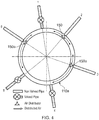
- Figure 4 illustrates one way in which the use of distributor devices of Figure 3 may be used to good effect but in a modified form 150a in which the deflecting surface has a varying curvature or curve function at different angular positions or in different angular regions or segments therearound, in order to direct cooling air non-uniformly or non-equally in different directions therearound.
- Figure 4 represents the asymmetrical layout of valved and non-valved compressor off-take pipes feeding cooling air into an engine manifold 110a, in which the non-valved pipes nos. 2 and 6 are provided with respective modified distributor devices 150a.
- the air from all three non-valved compressor offtake pipes is re-directed predominantly circumferentially (relative to the longitudinal axis of the engine), yet in such a way that substantially no dead zones in the secondary air system are assured.
- This is achieved by designing the curvature function of the deflecting surface of the modified distributor devices 150a such that it has a steeper or higher (or alternatively shallower or lower) gradient of curvature, and/or a different curve function altogether, in one or more selected angular regions or segments thereof, such that airflow in one or more respective selected directions corresponding to the said respective selected angular regions or segments occurs with a relatively higher or lower flow rate.
- greater (or lesser) airflow rates may be selectively directed in one or more desired directions around the distributor device, e.g. in order to increase the overall uniformity of the cooling effects of the airflow at different locations within the engine space 112a characteristic of the asymmetrical layout or spatial arrangement of the valved and non-valved pipes.
- the resulting arrangement is such that rotational asymmetry of the air deflector 180a provides an optimised asymmetrical airflow in different circumferential direction within the engine manifold 110a, as follows:
- FIGS 5(a), (b) and (c) show an alternative configuration of a distributor device included for background information only.
- the features which correspond to features of the first embodiment distributor device of Figure 3 are labelled with corresponding reference numerals but incremented by 100.
- a manifold 210 of a turbofan engine defines a space 212 within the casing 206 into which cooling air 222, e.g. HP3 air, is to be distributed for cooling of components therein.
- An e.g. cylindrical air inlet 230 is provided in a HP delivery pipe boss in a corresponding manner to the air inlet 130 of the first embodiment of Figure 3 .
- Mounted substantially centrally and concentrically within the air inlet 230 is air distributor device 250.
- the air distributor device 250 of this embodiment comprises a cylindrical tubular base 260 and an air deflector 280.
- the cylindrical base 260 is fixedly mounted within the mouth of the air inlet 230 by e.g. welding via an annular flange 233 (e.g. which may be square, circular, triangular or other polygonal shape) that lies against the casing 206 and is likewise welded thereto.
- the air deflector 280 is mounted via its periphery on the cylindrical base 260 via an array of e.g. four (or other suitable number of) axially configured and/or positioned (i.e. axially relative to the longitudinal axis of the air inlet 230) mounting struts or arm 272.
- the mounting struts or arms 272 are arranged equiangularly around the cylindrical base 260. They are attached or fixed at their radially outermost ends to the base 260, e.g. by welding or by being formed integrally therewith, and at their radially innermost ends to (likewise by welding or by being formed integrally therewith) an annular land or flange 277 which has attached thereto or carries the air deflector 280.
- the air deflector 280 which characterises this distributor device comprises a deflecting surface 290 which may have substantially the same or a similar shape to the deflecting surface 190 of the first embodiment shown in Figure 3 .
- a deflecting surface 290 which may have substantially the same or a similar shape to the deflecting surface 190 of the first embodiment shown in Figure 3 .
- optional and/or desirable and/or preferred features of the deflecting surface 190 of that first embodiment deflector 180 apply also to the deflecting surface 290 of this deflector 280, so will not be reiterated here, for brevity.
- the deflector 280 instead of the curved deflecting surface 290 extending all the way up to and merging with an axial spine of the deflector, which in this embodiment may be absent (especially since the deflector is mounted on the base via its periphery, not by radial ribs or vanes), it may usefully be shaped with a central region in the form of a convex dome or peak 296 which terminates at a distance from the lower edges of the cylindrical base 260 so as to define between the dome or peak 296 and the base 260 a gap for passage therethrough of cooling air as it flows through the device 250.
- the dome or peak 296 serves to facilitate the turning of the cooling air as it enters the device 250 from the inlet 230 and is directed into the desired directions by the deflecting surface 290.
- the walls of the cylindrical base 260 are provided, e.g. by post-production machining or cutting or integral forming, with apertures or windows 298 therein.
- the deflecting surface 290 of the deflector 280 may be substantially of the same curved shape as the deflecting surface 190 of the deflector 180 of the first embodiment as shown in Figure 3 , its function may likewise be correspondingly the same as in that first embodiment and as described above, so will not be reiterated here, for brevity.
- FIGS 6(a) , (b) , (c) , (d) and (e) show a second embodiment of a distributor device in accordance with the invention, in which features thereof which correspond to features of the first embodiment distributor device of Figure 3 are labelled with corresponding reference numerals but incremented by 200.
- the deflector 380 is constructed and configured so as to bias the cooling airflow in one of two opposite directions with a higher (or lower) flow rate than in the other one of the two opposite directions, in order for example to account for asymmetrical air feed pipe distributions within the engine architecture.
- the general manner of mounting of the distributor device 350 on the engine manifold 310 within air inlet 330 substantially corresponds to that of the first embodiment of Figures 3 and 5 , as will be readily appreciated and understood by persons skilled in the art.
- the configuration and arrangement of the deflecting surface of the deflector 380 is different.
- each respective deflecting surface portion 390A, 390B has its own unique curvature. That curvature of each respective deflecting surface portion 390A, 390B may be a unique or different one of a plurality of different mathematical functions, or values ascribed thereto, such as any of those used to define the curvatures of the deflecting surfaces of any of the first embodiment distributor devices of Figures 3 .
- the first deflecting surface portion 390A may have a first curvature C A and the second deflecting surface portion 390B may have a second curvature C B , the mathematical function which defines C A being different in form or ascribed values from that/those which define(s) C B .
- first and second deflecting surface portions 390A, 390B terminate at their longitudinally (relative to the air inlet passageway 330) outermost ends by blending smoothly into a central spine 382, with which they are preferably integrally formed.
- the spine 382 is located within cylindrical base 360 (as seen more clearly in Figure 6(b) ) and is anchored therein, e.g. by welding of its sides or lateral edges, to the inner walls of the cylindrical base 360.
- the respective deflecting surface portions 390A, 390B - or at least the spine 382 from which they extend - may each be positioned asymmetrically or offset within or with respect to the cylindrical base 360 and thus the or the respective air inlet 330.
- the spine 382 from which extend the respective deflecting surface portions 390A, 390B may for example be positioned in a chordal spatial position relative to the air inlet passageway 330.
- the spine 382 extends between, or spans a gap between, the side walls of the cylindrical base 360, and thereby partitions the available air inlet passageway 330 into two discrete airflow sections, each with a different cross-sectional area and/or a different air flow rate.
- deflecting surface portions 390A, 390B of the deflector 380 of this second embodiment may in principle act in much the same way as the deflecting surface 190 of the deflector 180 of the first embodiment as shown in Figure 3 , their function may likewise be correspondingly the same as in that first embodiment and as described above, so will not be reiterated here, for brevity.
Landscapes
- Engineering & Computer Science (AREA)
- Mechanical Engineering (AREA)
- General Engineering & Computer Science (AREA)
- Chemical & Material Sciences (AREA)
- Combustion & Propulsion (AREA)
- Physics & Mathematics (AREA)
- Fluid Mechanics (AREA)
- Turbine Rotor Nozzle Sealing (AREA)
Claims (11)
- Dispositif de distribution pour moteur à turbine à gaz (150 ; 350) pour la distribution d'air de refroidissement,
le dispositif (150 ; 350) comprenant : une embase (160; 360) montée dans une position adjacente à une entrée (130; 330) pour une distribution d'air ; et
un déflecteur (180; 380) supporté par l'embase (160; 360) et en communication fluidique avec une entrée d'air (130; 330), le déflecteur (180; 380) étant configuré pour diriger de l'air depuis l'entrée d'air (130; 330) dans une pluralité de directions au sein du moteur à turbine à gaz (101) ;
le déflecteur (180; 380) comprenant une ou plusieurs surfaces déflectrices curvilignes (190; 390A, 390B) pour diriger ledit air de façon différentielle dans une pluralité de directions désirées au sein du moteur à turbine à gaz (101) ;
caractérisé en ce que :le déflecteur est supporté par l'embase à travers une ossature (182, 382) située au sein de l'entrée d'air, et l'embase (160; 260) comprenant un support tubulaire (160) monté au sein d'une embouchure de la ou de l'entrée d'air correspondante (130), et l'ossature étant supportée au sein du support tubulaire (160) par le fait de son montage sur celui-ci à travers un ou plusieurs supports, tirants, nervures, pales, contre-fiches, bras, ou autres éléments de supportl'ossature étant une ossature centrale ou axiale (182) constituant une partie d'ancrage sur laquelle est montée ou fixée la pluralité d'éléments de support (172), et de laquelle sont déployées la(les) surface(s) déflectrice(s) (190) du déflecteur (180) avec un écart entre ladite (lesdites) surface(s) déflectrice(s) (190) et le support tubulaire (160) pour permettre le passage à travers de l'air distribué ou dirigé après son incidence sur la ou les surfaces déflectrices (190). - Dispositif de distribution (150) selon la revendication 1, la ou plusieurs surfaces déflectrices (190) curvilignes étant configurées pour diriger de l'air dans chacune d'une pluralité de directions de déplacement diverses et non parallèles.
- Dispositif de distribution (150) selon la revendication 2, la ou plusieurs surfaces déflectrices (190) curvilignes du déflecteur (180) est/sont recourbée(s) dans au moins deux plans non parallèles entre eux, lesdits plans étant définis comme étant (i) chacun généralement parallèle à la direction du débit d'air de l'entrée d'air ou l'entrée d'air correspondante (130) et incident sur la(les) surface(s) déflectrice(s) (190), et (ii) inclinés l'un par rapport à l'autre à un angle compris entre 0° et 180°.
- Dispositif de distribution (150) selon une quelconque des revendications précédentes, une dite surface déflectrice (190) présentant une courbure ou fonction de courbe uniforme l'entourant substantiellement de façon intégrale 360°, de l'air pouvant ainsi être dirigé substantiellement de façon uniforme ou égale dans toutes les directions autour de celle-ci.
- Dispositif de distribution (150) selon une quelconque des revendications 1 à 3, la surface déflectrice (190) présentant une courbure ou fonction de courbe variable à différentes positions angulaires ou dans différents segments ou régions angulaires autour de celle-ci, l'air pouvant être dirigé de façon non uniforme ou non égale dans différentes directions autour de celle-ci.
- Dispositif de distribution (150) selon une quelconque des revendications précédentes, dans lequel :(i) lesdits plusieurs supports, tirants, nervures, pales, contre-fiches, bras, et autres éléments de support (172) sont alignés entre eux de façon substantiellement uniforme, et sont tous substantiellement parallèles à la direction du débit d'air, de l'entrée d'air (130) jusqu'à la(les)surface(s) déflectrice(s) (190) du déflecteur (180) ; ou(ii) lesdits plusieurs supports, tirants, nervures, pales, contre-fiches, bras, et autres éléments de support (172) présentant chacun une configuration hélicoïdale.
- Dispositif de distribution (350) selon la revendication 1 ou selon la revendication 2, chaque surface déflectrice respective (390A, 390B) présentant une courbure unique qui lui est propre, qui est différente de la(des) courbure(s) d'au moins certaines de(des) autre(s) surface(s) du déflecteur (390A, 390B), de sorte que la ou plusieurs surfaces déflectrices curvilinéaires (390A, 390B) soient configurées pour diriger de l'air à différents débits dans une pluralité des différentes directions désirées.
- Dispositif de distribution (350) selon une quelconque des revendications précédentes, dans lequel, aux fins de la réalisation ou de l'établissement d'un certain débit d'air désiré effectué par chacune des surfaces déflectrices (390A, 390B) respectives, les surfaces déflectrices (390A, 390B) respectives étant positionnées chacune de façon asymétrique ou décalée par rapport à l'entrée d'air ou à l'entrée d'air respective (330).
- Dispositif de distribution (350) selon la revendication 8, les surfaces déflectrices (390A, 390B) étant supportées par une ossature (382) montée de façon asymétrique ou décalée au sein de l'entrée d'air ou à l'entrée d'air respective (330), ou relativement à cette dernière, le débit d'air traversant le dispositif (350) étant divisé de façon asymétrique en une pluralité de sections de débit d'air discrètes, présentant chacune une surface transversale diverse et/ou un débit divers.
- Collecteur de moteur à turbine à gaz (110; 210; 310) définissant un espace (112 312) pour la distribution, au sein de celui-ci, d'air de refroidissement, le collecteur (110 310) comprenant :au moins une entrée (130; 330) pour le refoulement d'air de refroidissement dans l'espace (112; 312);au moins un dispositif de distribution respectif (150 ; 350) selon une quelconque des revendications 1 à 9, pour la distribution d'air de refroidissement dans l'espace (112; 312).
- Moteur à turbine à gaz (101) comprenant :un espace (112; 312) pour la distribution, au sein de celui-ci, d'air de refroidissement ;au moins une entrée d'air (130; 330) pour le refoulement d'air de refroidissement dans l'espace (112; 312); etau moins un dispositif de distribution respectif (150; 350) selon une quelconque des revendications 1 à 9, pour la distribution d'air de refroidissement dans l'espace (112; 312).
Applications Claiming Priority (1)
| Application Number | Priority Date | Filing Date | Title |
|---|---|---|---|
| GBGB1408543.5A GB201408543D0 (en) | 2014-05-14 | 2014-05-14 | Distributor device for cooling air within an engine |
Publications (2)
| Publication Number | Publication Date |
|---|---|
| EP2944768A1 EP2944768A1 (fr) | 2015-11-18 |
| EP2944768B1 true EP2944768B1 (fr) | 2017-03-15 |
Family
ID=51032748
Family Applications (1)
| Application Number | Title | Priority Date | Filing Date |
|---|---|---|---|
| EP15165171.8A Not-in-force EP2944768B1 (fr) | 2014-05-14 | 2015-04-27 | Dispositif distributeur pour refroidir l'air à l'intérieur d'un moteur |
Country Status (3)
| Country | Link |
|---|---|
| US (1) | US9920643B2 (fr) |
| EP (1) | EP2944768B1 (fr) |
| GB (1) | GB201408543D0 (fr) |
Families Citing this family (13)
| Publication number | Priority date | Publication date | Assignee | Title |
|---|---|---|---|---|
| US9926789B2 (en) | 2015-05-08 | 2018-03-27 | United Technologies Corporation | Flow splitting baffle |
| JP6647952B2 (ja) * | 2016-04-25 | 2020-02-14 | 三菱重工業株式会社 | ガスタービン |
| FR3054263B1 (fr) * | 2016-07-20 | 2018-08-10 | Safran Aircraft Engines | Carter intermediaire de turbomachine d'aeronef realise d'une seule piece de fonderie avec une canalisation de lubrifiant |
| EP3342991B1 (fr) * | 2016-12-30 | 2020-10-14 | Ansaldo Energia IP UK Limited | Déflecteurs pour le refroidissement dans une turbine à gaz |
| US10718267B2 (en) * | 2017-12-14 | 2020-07-21 | Rolls-Royce Corporation | Turbine engine cooling with substantially uniform cooling air flow distribution |
| US10738637B2 (en) * | 2017-12-22 | 2020-08-11 | Raytheon Technologies Corporation | Airflow deflector and assembly |
| US20190234235A1 (en) * | 2018-01-31 | 2019-08-01 | United Technologies Corporation | Vane flow diverter |
| US10982546B2 (en) * | 2018-09-19 | 2021-04-20 | General Electric Company | Flow-diverting systems for gas turbine air separator |
| US11698005B2 (en) | 2020-02-07 | 2023-07-11 | Raytheon Technologies Corporation | Flow diverter for mid-turbine frame cooling air delivery |
| US11486262B2 (en) | 2021-03-03 | 2022-11-01 | General Electric Company | Diffuser bleed assembly |
| US20220316352A1 (en) * | 2021-03-31 | 2022-10-06 | Raytheon Technologies Corporation | Flow diverter for mid-turbine frame cooling air delivery |
| CN114542287A (zh) * | 2022-02-17 | 2022-05-27 | 中国航发沈阳发动机研究所 | 一种降低机匣壁面周向温度不均匀性的引气结构 |
| US12264685B1 (en) * | 2024-04-19 | 2025-04-01 | Rolls-Royce North American Technologies Inc. | Bleed valve assembly with valve shims for varying bleed flow in gas turbine engine compressors and method for operating |
Family Cites Families (13)
| Publication number | Priority date | Publication date | Assignee | Title |
|---|---|---|---|---|
| US3529941A (en) | 1967-04-24 | 1970-09-22 | Monsanto Co | Liquid deflection apparatus |
| US5224818A (en) * | 1991-11-01 | 1993-07-06 | General Electric Company | Air transfer bushing |
| US5239816A (en) * | 1992-03-16 | 1993-08-31 | General Electric Company | Steam deflector assembly for a steam injected gas turbine engine |
| US6234746B1 (en) | 1999-08-04 | 2001-05-22 | General Electric Co. | Apparatus and methods for cooling rotary components in a turbine |
| US6578462B1 (en) * | 2000-09-25 | 2003-06-17 | The United States Of America As Represented By The Secretary Of The Army | Radial-venting baffled muzzle brake |
| US6565313B2 (en) * | 2001-10-04 | 2003-05-20 | United Technologies Corporation | Bleed deflector for a gas turbine engine |
| US7108479B2 (en) * | 2003-06-19 | 2006-09-19 | General Electric Company | Methods and apparatus for supplying cooling fluid to turbine nozzles |
| US6929445B2 (en) * | 2003-10-22 | 2005-08-16 | General Electric Company | Split flow turbine nozzle |
| US7114638B2 (en) * | 2004-01-20 | 2006-10-03 | Xerox Corporation | Bin partitions to improve material flow |
| US8100633B2 (en) * | 2008-03-11 | 2012-01-24 | United Technologies Corp. | Cooling air manifold splash plates and gas turbines engine systems involving such splash plates |
| US8529195B2 (en) | 2010-10-12 | 2013-09-10 | General Electric Company | Inducer for gas turbine system |
| US8695352B2 (en) * | 2012-07-12 | 2014-04-15 | Solar Turbines Inc. | Baffle assembly for bleed air system of gas turbine engine |
| US9476429B2 (en) | 2012-12-19 | 2016-10-25 | United Technologies Corporation | Flow feed diffuser |
-
2014
- 2014-05-14 GB GBGB1408543.5A patent/GB201408543D0/en not_active Ceased
-
2015
- 2015-04-27 EP EP15165171.8A patent/EP2944768B1/fr not_active Not-in-force
- 2015-04-27 US US14/696,806 patent/US9920643B2/en not_active Expired - Fee Related
Also Published As
| Publication number | Publication date |
|---|---|
| EP2944768A1 (fr) | 2015-11-18 |
| US9920643B2 (en) | 2018-03-20 |
| GB201408543D0 (en) | 2014-06-25 |
| US20150330238A1 (en) | 2015-11-19 |
Similar Documents
| Publication | Publication Date | Title |
|---|---|---|
| US9920643B2 (en) | Distributor device for cooling air within an engine | |
| US10125684B2 (en) | Surface cooler for aero engine | |
| EP2101041B1 (fr) | Plaque de pulvérisation pour un distributeur d'air de refroidissement d'un moteur à turbine à gaz | |
| RU2599413C2 (ru) | Канал для охлаждения корпуса | |
| US6533546B2 (en) | Low-pressure steam turbine with multi-channel diffuser | |
| US9810081B2 (en) | Cooled conduit for conveying combustion gases | |
| RU2485356C2 (ru) | Диффузор турбомашины | |
| EP2141329B1 (fr) | Dispositif de refroidissement par impact | |
| RU2006144596A (ru) | Узел жаровой трубы (варианты) и способ регулирования температуры поверхности жаровой трубы | |
| EP2618057A1 (fr) | Micromélangeur d'un système de turbine | |
| US10422249B2 (en) | Exhaust frame | |
| CN108071491B (zh) | 用于冷却涡轮发动机的涡轮的连接组件 | |
| US20190170001A1 (en) | Impingement cooling of a blade platform | |
| US20160123186A1 (en) | Shroud assembly for a turbine engine | |
| CN105626160A (zh) | 涡轮叶片及用于冷却涡轮叶片与叶轮柱之间的轮缘间隙的方法 | |
| US20180274370A1 (en) | Engine component for a gas turbine engine | |
| KR950013206B1 (ko) | 오그먼터용 라이너의 냉각장치 | |
| WO2018205889A1 (fr) | Pelle de retournement d'extrémité de tête pour une turbine à gaz | |
| CN103518037B (zh) | 一种用于涡轮发动机涡轮的扇形喷管和涡轮发动机 | |
| US8002521B2 (en) | Flow machine | |
| US9810434B2 (en) | Transition duct system with arcuate ceramic liner for delivering hot-temperature gases in a combustion turbine engine | |
| CN109906309B (zh) | 涡轮机的涡轮的冷却装置 | |
| EP3189276B1 (fr) | Turbine à gaz avec un chambre de combustion comprenant des aubes de régulation d'écoulement | |
| JP4526420B2 (ja) | ターボマシンの高圧タービンのステータおよびステータの組立方法 | |
| WO2020086069A1 (fr) | Système de conduit de transition comprenant des chemises thermiquement isolantes non métalliques supportées par des structures de coque métalliques divisibles pour distribuer des gaz à température chaude dans un moteur à turbine à combustion |
Legal Events
| Date | Code | Title | Description |
|---|---|---|---|
| PUAI | Public reference made under article 153(3) epc to a published international application that has entered the european phase |
Free format text: ORIGINAL CODE: 0009012 |
|
| AK | Designated contracting states |
Kind code of ref document: A1 Designated state(s): AL AT BE BG CH CY CZ DE DK EE ES FI FR GB GR HR HU IE IS IT LI LT LU LV MC MK MT NL NO PL PT RO RS SE SI SK SM TR |
|
| AX | Request for extension of the european patent |
Extension state: BA ME |
|
| 17P | Request for examination filed |
Effective date: 20160511 |
|
| RBV | Designated contracting states (corrected) |
Designated state(s): AL AT BE BG CH CY CZ DE DK EE ES FI FR GB GR HR HU IE IS IT LI LT LU LV MC MK MT NL NO PL PT RO RS SE SI SK SM TR |
|
| GRAP | Despatch of communication of intention to grant a patent |
Free format text: ORIGINAL CODE: EPIDOSNIGR1 |
|
| STAA | Information on the status of an ep patent application or granted ep patent |
Free format text: STATUS: GRANT OF PATENT IS INTENDED |
|
| INTG | Intention to grant announced |
Effective date: 20170103 |
|
| GRAS | Grant fee paid |
Free format text: ORIGINAL CODE: EPIDOSNIGR3 |
|
| GRAA | (expected) grant |
Free format text: ORIGINAL CODE: 0009210 |
|
| STAA | Information on the status of an ep patent application or granted ep patent |
Free format text: STATUS: THE PATENT HAS BEEN GRANTED |
|
| AK | Designated contracting states |
Kind code of ref document: B1 Designated state(s): AL AT BE BG CH CY CZ DE DK EE ES FI FR GB GR HR HU IE IS IT LI LT LU LV MC MK MT NL NO PL PT RO RS SE SI SK SM TR |
|
| REG | Reference to a national code |
Ref country code: CH Ref legal event code: EP Ref country code: GB Ref legal event code: FG4D |
|
| REG | Reference to a national code |
Ref country code: IE Ref legal event code: FG4D |
|
| REG | Reference to a national code |
Ref country code: AT Ref legal event code: REF Ref document number: 875813 Country of ref document: AT Kind code of ref document: T Effective date: 20170415 |
|
| REG | Reference to a national code |
Ref country code: FR Ref legal event code: PLFP Year of fee payment: 3 |
|
| REG | Reference to a national code |
Ref country code: DE Ref legal event code: R096 Ref document number: 602015001798 Country of ref document: DE |
|
| REG | Reference to a national code |
Ref country code: NL Ref legal event code: MP Effective date: 20170315 |
|
| REG | Reference to a national code |
Ref country code: LT Ref legal event code: MG4D |
|
| PG25 | Lapsed in a contracting state [announced via postgrant information from national office to epo] |
Ref country code: GR Free format text: LAPSE BECAUSE OF FAILURE TO SUBMIT A TRANSLATION OF THE DESCRIPTION OR TO PAY THE FEE WITHIN THE PRESCRIBED TIME-LIMIT Effective date: 20170616 Ref country code: FI Free format text: LAPSE BECAUSE OF FAILURE TO SUBMIT A TRANSLATION OF THE DESCRIPTION OR TO PAY THE FEE WITHIN THE PRESCRIBED TIME-LIMIT Effective date: 20170315 Ref country code: NO Free format text: LAPSE BECAUSE OF FAILURE TO SUBMIT A TRANSLATION OF THE DESCRIPTION OR TO PAY THE FEE WITHIN THE PRESCRIBED TIME-LIMIT Effective date: 20170615 Ref country code: LT Free format text: LAPSE BECAUSE OF FAILURE TO SUBMIT A TRANSLATION OF THE DESCRIPTION OR TO PAY THE FEE WITHIN THE PRESCRIBED TIME-LIMIT Effective date: 20170315 Ref country code: HR Free format text: LAPSE BECAUSE OF FAILURE TO SUBMIT A TRANSLATION OF THE DESCRIPTION OR TO PAY THE FEE WITHIN THE PRESCRIBED TIME-LIMIT Effective date: 20170315 |
|
| REG | Reference to a national code |
Ref country code: AT Ref legal event code: MK05 Ref document number: 875813 Country of ref document: AT Kind code of ref document: T Effective date: 20170315 |
|
| PG25 | Lapsed in a contracting state [announced via postgrant information from national office to epo] |
Ref country code: BG Free format text: LAPSE BECAUSE OF FAILURE TO SUBMIT A TRANSLATION OF THE DESCRIPTION OR TO PAY THE FEE WITHIN THE PRESCRIBED TIME-LIMIT Effective date: 20170615 Ref country code: LV Free format text: LAPSE BECAUSE OF FAILURE TO SUBMIT A TRANSLATION OF THE DESCRIPTION OR TO PAY THE FEE WITHIN THE PRESCRIBED TIME-LIMIT Effective date: 20170315 Ref country code: RS Free format text: LAPSE BECAUSE OF FAILURE TO SUBMIT A TRANSLATION OF THE DESCRIPTION OR TO PAY THE FEE WITHIN THE PRESCRIBED TIME-LIMIT Effective date: 20170315 Ref country code: SE Free format text: LAPSE BECAUSE OF FAILURE TO SUBMIT A TRANSLATION OF THE DESCRIPTION OR TO PAY THE FEE WITHIN THE PRESCRIBED TIME-LIMIT Effective date: 20170315 |
|
| PG25 | Lapsed in a contracting state [announced via postgrant information from national office to epo] |
Ref country code: NL Free format text: LAPSE BECAUSE OF FAILURE TO SUBMIT A TRANSLATION OF THE DESCRIPTION OR TO PAY THE FEE WITHIN THE PRESCRIBED TIME-LIMIT Effective date: 20170315 |
|
| PG25 | Lapsed in a contracting state [announced via postgrant information from national office to epo] |
Ref country code: SK Free format text: LAPSE BECAUSE OF FAILURE TO SUBMIT A TRANSLATION OF THE DESCRIPTION OR TO PAY THE FEE WITHIN THE PRESCRIBED TIME-LIMIT Effective date: 20170315 Ref country code: IT Free format text: LAPSE BECAUSE OF FAILURE TO SUBMIT A TRANSLATION OF THE DESCRIPTION OR TO PAY THE FEE WITHIN THE PRESCRIBED TIME-LIMIT Effective date: 20170315 Ref country code: ES Free format text: LAPSE BECAUSE OF FAILURE TO SUBMIT A TRANSLATION OF THE DESCRIPTION OR TO PAY THE FEE WITHIN THE PRESCRIBED TIME-LIMIT Effective date: 20170315 Ref country code: CZ Free format text: LAPSE BECAUSE OF FAILURE TO SUBMIT A TRANSLATION OF THE DESCRIPTION OR TO PAY THE FEE WITHIN THE PRESCRIBED TIME-LIMIT Effective date: 20170315 Ref country code: AT Free format text: LAPSE BECAUSE OF FAILURE TO SUBMIT A TRANSLATION OF THE DESCRIPTION OR TO PAY THE FEE WITHIN THE PRESCRIBED TIME-LIMIT Effective date: 20170315 Ref country code: RO Free format text: LAPSE BECAUSE OF FAILURE TO SUBMIT A TRANSLATION OF THE DESCRIPTION OR TO PAY THE FEE WITHIN THE PRESCRIBED TIME-LIMIT Effective date: 20170315 Ref country code: EE Free format text: LAPSE BECAUSE OF FAILURE TO SUBMIT A TRANSLATION OF THE DESCRIPTION OR TO PAY THE FEE WITHIN THE PRESCRIBED TIME-LIMIT Effective date: 20170315 |
|
| PG25 | Lapsed in a contracting state [announced via postgrant information from national office to epo] |
Ref country code: SM Free format text: LAPSE BECAUSE OF FAILURE TO SUBMIT A TRANSLATION OF THE DESCRIPTION OR TO PAY THE FEE WITHIN THE PRESCRIBED TIME-LIMIT Effective date: 20170315 Ref country code: PT Free format text: LAPSE BECAUSE OF FAILURE TO SUBMIT A TRANSLATION OF THE DESCRIPTION OR TO PAY THE FEE WITHIN THE PRESCRIBED TIME-LIMIT Effective date: 20170717 Ref country code: IS Free format text: LAPSE BECAUSE OF FAILURE TO SUBMIT A TRANSLATION OF THE DESCRIPTION OR TO PAY THE FEE WITHIN THE PRESCRIBED TIME-LIMIT Effective date: 20170715 Ref country code: PL Free format text: LAPSE BECAUSE OF FAILURE TO SUBMIT A TRANSLATION OF THE DESCRIPTION OR TO PAY THE FEE WITHIN THE PRESCRIBED TIME-LIMIT Effective date: 20170315 |
|
| REG | Reference to a national code |
Ref country code: DE Ref legal event code: R097 Ref document number: 602015001798 Country of ref document: DE |
|
| PLBE | No opposition filed within time limit |
Free format text: ORIGINAL CODE: 0009261 |
|
| STAA | Information on the status of an ep patent application or granted ep patent |
Free format text: STATUS: NO OPPOSITION FILED WITHIN TIME LIMIT |
|
| REG | Reference to a national code |
Ref country code: IE Ref legal event code: MM4A |
|
| PG25 | Lapsed in a contracting state [announced via postgrant information from national office to epo] |
Ref country code: MC Free format text: LAPSE BECAUSE OF FAILURE TO SUBMIT A TRANSLATION OF THE DESCRIPTION OR TO PAY THE FEE WITHIN THE PRESCRIBED TIME-LIMIT Effective date: 20170315 Ref country code: DK Free format text: LAPSE BECAUSE OF FAILURE TO SUBMIT A TRANSLATION OF THE DESCRIPTION OR TO PAY THE FEE WITHIN THE PRESCRIBED TIME-LIMIT Effective date: 20170315 |
|
| 26N | No opposition filed |
Effective date: 20171218 |
|
| PG25 | Lapsed in a contracting state [announced via postgrant information from national office to epo] |
Ref country code: SI Free format text: LAPSE BECAUSE OF FAILURE TO SUBMIT A TRANSLATION OF THE DESCRIPTION OR TO PAY THE FEE WITHIN THE PRESCRIBED TIME-LIMIT Effective date: 20170315 Ref country code: LU Free format text: LAPSE BECAUSE OF NON-PAYMENT OF DUE FEES Effective date: 20170427 |
|
| REG | Reference to a national code |
Ref country code: BE Ref legal event code: MM Effective date: 20170430 |
|
| REG | Reference to a national code |
Ref country code: FR Ref legal event code: PLFP Year of fee payment: 4 |
|
| PG25 | Lapsed in a contracting state [announced via postgrant information from national office to epo] |
Ref country code: IE Free format text: LAPSE BECAUSE OF NON-PAYMENT OF DUE FEES Effective date: 20170427 |
|
| PG25 | Lapsed in a contracting state [announced via postgrant information from national office to epo] |
Ref country code: BE Free format text: LAPSE BECAUSE OF NON-PAYMENT OF DUE FEES Effective date: 20170430 |
|
| PG25 | Lapsed in a contracting state [announced via postgrant information from national office to epo] |
Ref country code: MT Free format text: LAPSE BECAUSE OF NON-PAYMENT OF DUE FEES Effective date: 20170427 |
|
| REG | Reference to a national code |
Ref country code: CH Ref legal event code: PL |
|
| PG25 | Lapsed in a contracting state [announced via postgrant information from national office to epo] |
Ref country code: LI Free format text: LAPSE BECAUSE OF NON-PAYMENT OF DUE FEES Effective date: 20180430 Ref country code: CH Free format text: LAPSE BECAUSE OF NON-PAYMENT OF DUE FEES Effective date: 20180430 |
|
| PG25 | Lapsed in a contracting state [announced via postgrant information from national office to epo] |
Ref country code: HU Free format text: LAPSE BECAUSE OF FAILURE TO SUBMIT A TRANSLATION OF THE DESCRIPTION OR TO PAY THE FEE WITHIN THE PRESCRIBED TIME-LIMIT; INVALID AB INITIO Effective date: 20150427 |
|
| PG25 | Lapsed in a contracting state [announced via postgrant information from national office to epo] |
Ref country code: CY Free format text: LAPSE BECAUSE OF FAILURE TO SUBMIT A TRANSLATION OF THE DESCRIPTION OR TO PAY THE FEE WITHIN THE PRESCRIBED TIME-LIMIT Effective date: 20170315 |
|
| PG25 | Lapsed in a contracting state [announced via postgrant information from national office to epo] |
Ref country code: MK Free format text: LAPSE BECAUSE OF FAILURE TO SUBMIT A TRANSLATION OF THE DESCRIPTION OR TO PAY THE FEE WITHIN THE PRESCRIBED TIME-LIMIT Effective date: 20170315 |
|
| PG25 | Lapsed in a contracting state [announced via postgrant information from national office to epo] |
Ref country code: TR Free format text: LAPSE BECAUSE OF FAILURE TO SUBMIT A TRANSLATION OF THE DESCRIPTION OR TO PAY THE FEE WITHIN THE PRESCRIBED TIME-LIMIT Effective date: 20170315 |
|
| PG25 | Lapsed in a contracting state [announced via postgrant information from national office to epo] |
Ref country code: AL Free format text: LAPSE BECAUSE OF FAILURE TO SUBMIT A TRANSLATION OF THE DESCRIPTION OR TO PAY THE FEE WITHIN THE PRESCRIBED TIME-LIMIT Effective date: 20170315 |
|
| PGFP | Annual fee paid to national office [announced via postgrant information from national office to epo] |
Ref country code: FR Payment date: 20200429 Year of fee payment: 6 |
|
| PGFP | Annual fee paid to national office [announced via postgrant information from national office to epo] |
Ref country code: GB Payment date: 20200429 Year of fee payment: 6 |
|
| PGFP | Annual fee paid to national office [announced via postgrant information from national office to epo] |
Ref country code: DE Payment date: 20200629 Year of fee payment: 6 |
|
| REG | Reference to a national code |
Ref country code: DE Ref legal event code: R119 Ref document number: 602015001798 Country of ref document: DE |
|
| GBPC | Gb: european patent ceased through non-payment of renewal fee |
Effective date: 20210427 |
|
| PG25 | Lapsed in a contracting state [announced via postgrant information from national office to epo] |
Ref country code: DE Free format text: LAPSE BECAUSE OF NON-PAYMENT OF DUE FEES Effective date: 20211103 Ref country code: GB Free format text: LAPSE BECAUSE OF NON-PAYMENT OF DUE FEES Effective date: 20210427 Ref country code: FR Free format text: LAPSE BECAUSE OF NON-PAYMENT OF DUE FEES Effective date: 20210430 |