EP2944828B1 - Energierückführendes hydraulische steuerhauptventil - Google Patents
Energierückführendes hydraulische steuerhauptventil Download PDFInfo
- Publication number
- EP2944828B1 EP2944828B1 EP13891811.5A EP13891811A EP2944828B1 EP 2944828 B1 EP2944828 B1 EP 2944828B1 EP 13891811 A EP13891811 A EP 13891811A EP 2944828 B1 EP2944828 B1 EP 2944828B1
- Authority
- EP
- European Patent Office
- Prior art keywords
- hole
- oil port
- valve core
- throttling
- disposed
- Prior art date
- Legal status (The legal status is an assumption and is not a legal conclusion. Google has not performed a legal analysis and makes no representation as to the accuracy of the status listed.)
- Active
Links
Images




Classifications
-
- F—MECHANICAL ENGINEERING; LIGHTING; HEATING; WEAPONS; BLASTING
- F16—ENGINEERING ELEMENTS AND UNITS; GENERAL MEASURES FOR PRODUCING AND MAINTAINING EFFECTIVE FUNCTIONING OF MACHINES OR INSTALLATIONS; THERMAL INSULATION IN GENERAL
- F16K—VALVES; TAPS; COCKS; ACTUATING-FLOATS; DEVICES FOR VENTING OR AERATING
- F16K11/00—Multiple-way valves, e.g. mixing valves; Pipe fittings incorporating such valves
- F16K11/02—Multiple-way valves, e.g. mixing valves; Pipe fittings incorporating such valves with all movable sealing faces moving as one unit
- F16K11/06—Multiple-way valves, e.g. mixing valves; Pipe fittings incorporating such valves with all movable sealing faces moving as one unit comprising only sliding valves, i.e. sliding closure elements
-
- F—MECHANICAL ENGINEERING; LIGHTING; HEATING; WEAPONS; BLASTING
- F15—FLUID-PRESSURE ACTUATORS; HYDRAULICS OR PNEUMATICS IN GENERAL
- F15B—SYSTEMS ACTING BY MEANS OF FLUIDS IN GENERAL; FLUID-PRESSURE ACTUATORS, e.g. SERVOMOTORS; DETAILS OF FLUID-PRESSURE SYSTEMS, NOT OTHERWISE PROVIDED FOR
- F15B13/00—Details of servomotor systems ; Valves for servomotor systems
- F15B13/02—Fluid distribution or supply devices characterised by their adaptation to the control of servomotors
- F15B13/04—Fluid distribution or supply devices characterised by their adaptation to the control of servomotors for use with a single servomotor
- F15B13/0401—Valve members; Fluid interconnections therefor
- F15B13/0402—Valve members; Fluid interconnections therefor for linearly sliding valves, e.g. spool valves
- F15B13/0403—Valve members; Fluid interconnections therefor for linearly sliding valves, e.g. spool valves a secondary valve member sliding within the main spool, e.g. for regeneration flow
-
- F—MECHANICAL ENGINEERING; LIGHTING; HEATING; WEAPONS; BLASTING
- F16—ENGINEERING ELEMENTS AND UNITS; GENERAL MEASURES FOR PRODUCING AND MAINTAINING EFFECTIVE FUNCTIONING OF MACHINES OR INSTALLATIONS; THERMAL INSULATION IN GENERAL
- F16K—VALVES; TAPS; COCKS; ACTUATING-FLOATS; DEVICES FOR VENTING OR AERATING
- F16K11/00—Multiple-way valves, e.g. mixing valves; Pipe fittings incorporating such valves
- F16K11/02—Multiple-way valves, e.g. mixing valves; Pipe fittings incorporating such valves with all movable sealing faces moving as one unit
- F16K11/06—Multiple-way valves, e.g. mixing valves; Pipe fittings incorporating such valves with all movable sealing faces moving as one unit comprising only sliding valves, i.e. sliding closure elements
- F16K11/065—Multiple-way valves, e.g. mixing valves; Pipe fittings incorporating such valves with all movable sealing faces moving as one unit comprising only sliding valves, i.e. sliding closure elements with linearly sliding closure members
- F16K11/07—Multiple-way valves, e.g. mixing valves; Pipe fittings incorporating such valves with all movable sealing faces moving as one unit comprising only sliding valves, i.e. sliding closure elements with linearly sliding closure members with cylindrical slides
- F16K11/0716—Multiple-way valves, e.g. mixing valves; Pipe fittings incorporating such valves with all movable sealing faces moving as one unit comprising only sliding valves, i.e. sliding closure elements with linearly sliding closure members with cylindrical slides with fluid passages through the valve member
-
- Y—GENERAL TAGGING OF NEW TECHNOLOGICAL DEVELOPMENTS; GENERAL TAGGING OF CROSS-SECTIONAL TECHNOLOGIES SPANNING OVER SEVERAL SECTIONS OF THE IPC; TECHNICAL SUBJECTS COVERED BY FORMER USPC CROSS-REFERENCE ART COLLECTIONS [XRACs] AND DIGESTS
- Y10—TECHNICAL SUBJECTS COVERED BY FORMER USPC
- Y10T—TECHNICAL SUBJECTS COVERED BY FORMER US CLASSIFICATION
- Y10T137/00—Fluid handling
- Y10T137/8593—Systems
- Y10T137/86493—Multi-way valve unit
-
- Y—GENERAL TAGGING OF NEW TECHNOLOGICAL DEVELOPMENTS; GENERAL TAGGING OF CROSS-SECTIONAL TECHNOLOGIES SPANNING OVER SEVERAL SECTIONS OF THE IPC; TECHNICAL SUBJECTS COVERED BY FORMER USPC CROSS-REFERENCE ART COLLECTIONS [XRACs] AND DIGESTS
- Y10—TECHNICAL SUBJECTS COVERED BY FORMER USPC
- Y10T—TECHNICAL SUBJECTS COVERED BY FORMER US CLASSIFICATION
- Y10T137/00—Fluid handling
- Y10T137/8593—Systems
- Y10T137/86493—Multi-way valve unit
- Y10T137/86574—Supply and exhaust
- Y10T137/8667—Reciprocating valve
- Y10T137/86694—Piston valve
- Y10T137/86702—With internal flow passage
Definitions
- the present disclosure generally relates to a hydraulic control main valve, and more particularly, to an energy-recycling hydraulic control main valve.
- JP S61 236901 A discloses a hydraulic control valve according to the preamble of claim 1.
- An objective of the present disclosure is to provide an energy-recycling hydraulic control main valve, which can limit the falling speed of a piston and utilize the potential energy generated by the gravity action of the mechanism and the material on the piston, thereby overcoming the drawbacks of the prior art.
- an energy-recycling hydraulic control main valve which comprises end covers, a valve core, a left one-way valve and a right one-way valve; wherein each of two ends of the valve core is provided with one end cover, the valve core is controlling a left first oil port T, a second oil port A, a third oil port I/L, a fourth oil port I/M, a fifth oil port I/R, a sixth oil port B, a right seventh oil port T and an eighth oil port P thereon; a spring and a spring seat are arranged between each of the end covers and the valve core; the left one-way valve and the right one-way valve are respectively embedded in the left end and the right end of the valve core; the left one-way valve is composed of a a left valve seat, a left cone valve core and a left spring; a conical surface of the left cone valve core is closely attached to a left conical surface of the valve core by the
- a left thick central hole and a right thick central hole are symmetrically disposed on the central line of the valve core described in the aforesaid technical solution; the two thick central holes are in communication with each other via a thin central hole, and frustum holes are respectively formed at junctions of the thin central hole and each of the thick central holes; a left oil-feeding throttling groove and a right oil-feeding throttling groove are disposed between the eighth oil port P and the fourth oil port I/M; a left throttling groove is disposed between the second oil port A and the third oil port I/L; a left oil-returning hole assembly composed of a left first throttling hole, a left second throttling hole and a left third throttling hole is disposed between the left first oil port T and the third oil port I/L; the left second throttling hole is in communication with the second oil port A; a right throttling groove is disposed between the sixth oil port B and the fifth oil port I/R;
- a left first circular groove, a left second circular groove, a left first seal groove and a left second seal groove are disposed on the circumference of the left valve seat described in the aforesaid technical solution, and a left valve seat central hole is disposed on the central line of the left valve seat; the left first circular groove is in communication with the left valve seat central hole via a left valve seat radial hole that is disposed radially; and each of the left first seal groove and the left second seal groove is provided with a left seal ring; and a right first circular groove, a right second circular groove, a right first seal groove and a right second seal groove are disposed on the circumference of the right valve seat, and a right valve seat central hole is disposed on the central line of the right valve seat; the right first circular groove is in communication with the right valve seat central hole via a right valve seat radial hole that is disposed radially; and each of the right first seal groove and the right second seal groove is provided with a right seal ring.
- a left spring hole and a left cone valve core hole that are in communication with each other are disposed on the central line of the left cone valve core described in the aforesaid technical solution, and a left shoulder with a radial circular surface is provided at the right end of the left cone valve core; a left shoulder radial hole is disposed along a radial direction of the left shoulder, and the right end of the left shoulder is provided with a left shoulder conical surface; the left shoulder radial hole is in communication with the left cone valve core hole; and the angle of the left shoulder conical surface is smaller than the angle of the frustum holes; and a right spring hole and a right cone valve core hole that are in communication with each other are disposed on the central line of the right cone valve core, a right shoulder with a radial circular surface is provided at the right end of the right cone valve core; a right shoulder radial hole is disposed along a radial direction of the right shoulder, and the right end of the right shoulder is provided with a right shoulder conical surface
- An upper left pressure-releasing slant hole and a lower left pressure-releasing slant hole are disposed symmetrically near the left first oil port T described in the aforesaid technical solution; and an upper right pressure-releasing slant hole and a lower right pressure-releasing slant hole are disposed symmetrically near the right seventh oil port T.
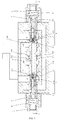
- an energy-recycling hydraulic control main valve comprises end covers 1, a valve core 2, a left one-way valve 3 and a right one-way valve 4; each of two ends of the valve core 2 is provided with one end cover 1, the valve core 2 is provided with a left first oil port T, a second oil port A, a third oil port I/L, a fourth oil port I/M, a fifth oil port I/R, a sixth oil port B, a right seventh oil port T and an eighth oil port P thereon; a spring 5 and a spring seat 6 are arranged between each of the end covers 1 and the valve core 2; the left one-way valve 3 and the right one-way valve 4 are respectively embedded in the left end and the right end of the valve core 2; the left one-way valve 3 is composed of a left valve seat 3-1, a left cone valve core 3-2 and a left spring 3-3; a conical surface of the left cone valve core 3-2 is closely attached to a left conical surface of the valve core 2 by the
- An upper left pressure-releasing slant hole and a lower left pressure-releasing slant hole 7 are disposed symmetrically near the left first oil port T; and an upper right pressure-releasing slant hole and a lower right pressure-releasing slant hole 8 are disposed symmetrically near the right seventh oil port T.
- a left thick central hole and a right thick central hole 2-1 are disposed symmetrically on the central line of the valve core 2; the two thick central holes 2-1 are in communication with each other via a thin central hole 2-2, and frustum holes 2-3 are respectively formed at junctions of the thin central hole 2-2 and each of the thick central holes 2-1; a left oil-feeding throttling groove 2-4 and a right oil-feeding throttling groove 2-5 are disposed between the eighth oil port P and the fourth oil port I/M; a left throttling groove 2-6 is disposed between the second oil port A and the third oil port I/L; a left oil-returning hole assembly composed of a left first throttling hole 2-7, a left second throttling hole 2-8 and a left third throttling hole 2-9 is disposed between the left first oil port T and the oil third port I/L; the left second throttling hole 2-8 is in communication with the second oil port A; a right
- a left first circular groove 3-1-1, a left second circular groove 3-1-2, a left first seal groove 3-1-3 and a left second seal groove 3-1-4 are disposed on the circumference of the left valve seat 3-1, and a left valve seat central hole 3-1-5 is disposed on the central line of the left valve seat 3-1; the left first circular groove 3-1-1 is in communication with the left valve seat central hole 3-1-5 via two left valve seat radial holes 3-1-6 that are disposed radially; and each of the left first seal groove 3-1-3 and the left second seal groove 3-1-4 is provided with a seal ring 3-1-7.
- a right first circular groove 4-1-1, a right second circular groove 4-1-2, a right first seal groove 4-1-3 and a right second seal groove 4-1-4 are disposed on the circumference of the right valve seat 4-1, and a right valve seat central hole 4-1-5 is disposed on the central line of the right valve seat 4-1; the right first circular groove 4-1-1 is in communication with the right valve seat central hole 4-1-5 via a right valve seat radial hole 4-1-6 that is disposed radially; and each of the right first seal groove 4-1-3 and the right second seal groove 4-1-4 is provided with a seal ring 4-1-7.
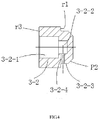
- a left spring hole 3-2-1 and a left cone valve core hole 3-2-2 that are in communication with each other are disposed on the central line of the left cone valve core 3-2, a left shoulder 3-2-3 with a radial circular surface is provided at the right end of the left cone valve core 3-2; a left shoulder radial hole 3-2-4 is disposed along a radial direction of the left shoulder 3-2-3, and the right end of the left shoulder 3-2-3 is provided with a left shoulder conical surface; the left shoulder radial hole 3-2-4 is in communication with the left cone valve core hole 3-2-2; and the angle of the left shoulder conical surface is smaller than the angle of the frustum holes.
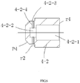
- a right spring hole 4-2-1 and a right cone valve core hole 4-2-2 that are in communication with each other are disposed on the central line of the right cone valve core 4-2, a right shoulder 4-2-3 with a radial circular surface is provided at the right end of the right cone valve core 4-2; two right shoulder radial holes 4-2-4 are disposed along a radial direction of the right shoulder 4-2-3, and the right end of the right shoulder 4-2-3 is provided with a right shoulder conical surface; the right shoulder radial holes 4-2-4 are in communication with the right cone valve core hole 4-2-2; and the angle of the right shoulder conical surface is smaller than the angle of the frustum holes.
- the two left seal rings 3-1-7 respectively isolate the left first circular groove 3-1-1 from the left second circular groove 3-1-2, and isolate the left second circular groove 3-1-2 from the left throttling groove 2-6;
- the two right seal rings 4-1-7 respectively isolate the right first circular groove 4-1-1 from the right second circular groove 4-1-2, and isolate the right second circular groove 4-1-2 from the right throttling groove 2-10;
- the positive overlap amount between the left third throttling hole 2-9 and the valve body is L2
- the positive overlap amount between the left pressure-releasing slant hole 7 and the valve body is L1;
- the left third throttling hole 2-9, the left throttling groove 2-6, the left cone valve core hole 3-2-2, the left shoulder radial hole 3-2-4, the left valve seat central hole 3-1-5, the two left valve seat radial holes 3-1-6, and the left pressure-releasing slant hole 7 are in communication to form a channel; and the right first first circular groove 3-1-1 from the left second circular groove 3-1-2, and isolate the left second circular
- the working principle of the present disclosure is as follows.
- the oil fluid flows from the eighth oil port P through the oil-feeding throttling groove 2-4 to the third oil port I/L, and then flows into the second oil port A through the throttling groove 2-6; and meanwhile, part of the oil fluid can flow from the third oil port I/L through the left third throttling hole 2-9 to the left throttling groove 2-6; the oil fluid flows from the left shoulder radial hole 3-2-4 and is in communication with the left cone valve core hole 3-2-2, the left valve seat central hole 3-1-5, the left valve seat radial hole 3-1-6, the left first circular groove 3-1-1, and the left pressure-releasing slant hole 7 and is then blocked; the pressure at the third oil port I/L is equal to the pressure at the left pressure-releasing slant hole 7; and a circular section r3 of the left cone valve core 3-2 is much greater than a circular surface r1, so the conical surface of the left cone valve core 3-2 is pushes towards and closely attached to the
- the oil fluid in the piston chamber of the oil cylinder flows back to the sixth oil port B, flows into the right second throttling hole 2-12 and the right first circular groove 4-1-1, and flows to the oil port T through the right third throttling hole 2-13; and another part of the oil fluid can flow from the sixth oil port B through the right first throttling hole 2-11 to the right throttling groove 2-10, the right shoulder radial hole 4-2-4, the right cone valve core hole 4-2-2 and the right valve seat central hole 4-1-5, and finally flows to the oil port T through the right pressure-releasing slant hole 8.
- the conical surface of the right cone valve core 4-2 is closely attached to the conical surface of the valve core 2.
- the oil fluid flows from the eighth oil port P through the right oil-feeding throttling groove 2-5 to the fifth oil port I/R, and then flows into the sixth oil port B through the right throttling groove 2-10; and meanwhile, part of the oil fluid can flow from the fifth oil port I/R through the right first throttling hole 2-11 to the right throttling groove 2-10; then the oil fluid flows from the two right shoulder radial holes 4-2-4 and is in communication with the right cone valve core hole 4-2-2, the right valve seat central hole 4-1-5, the right valve seat radial hole 4-1-6, the right second circular groove 4-1-2 and the right pressure-releasing slant hole 8, and finally flows into the oil tank; and the area of the two right shoulder radial hole 4-2-4 is larger than that of the right valve seat radial hole 4-1-6, so this part of the oil fluid only substantially generates the same pressure at the front end of the right valve seat radial hole 4-1-6.
- the oil fluid in the piston chamber of the oil cylinder flows back to the second oil port A, flows into the left second throttling hole 2-8 and the left second circular groove 3-1-2, and flows to the oil port T through the left first throttling hole 2-7; by limiting the open area of the left first throttling hole 2-7, a backpressure p1 is generated in the left first throttling hole 2-7 by the returning oil to avoid unrestricted falling of the piston; and meanwhile, another part of the oil fluid can flow from the second oil port A through left third throttle hole 2-9 and the left shoulder radial hole 3-2-4, flow into the left spring hole 3-2-1, then through the left valve seat central hole 3-1-5, two left valve seat radial holes 3-1-6 and the left first circular groove 3-1-1, and finally flow to the oil port T through the left pressure-releasing slant hole7.
- the backpressure p1 acts on the right end surface r1 of the left cone valve core 3-2 to overcome the force of the left spring 3-3 so that the conical surface P2 of the left cone valve core 3-2 is separated from the conical surface P1 of the valve core 2.
- the oil fluid can flow into the thin central line 2-2 and open the right core valve cone, then flow through the right first throttling hole 2-11, and finally flow into the sixth oil port B and push the piston to move downward together with the oil fluid from the eighth oil port P, thereby achieving energy recycling and reducing the necessary power of the motor.
- the backpressure p1 cannot push the right end surface of the left cone valve core 3-2 to overcome the force of the left spring 3-3 4-3 so as to separate the conical surface P2 of the left cone valve core 3-2 from the conical surface P1 of the valve core 2, so this will not influence the micro-operation of the oil cylinder.
Landscapes
- Engineering & Computer Science (AREA)
- General Engineering & Computer Science (AREA)
- Mechanical Engineering (AREA)
- Physics & Mathematics (AREA)
- Fluid Mechanics (AREA)
- Lift Valve (AREA)
- Fluid-Pressure Circuits (AREA)
- Safety Valves (AREA)
Claims (4)
- Energie rückgewinnendes hydraulisches Steuerhauptventil, das Endabdeckungen (1), einen Ventileinsatz (2), ein linkes Einwegventil (3) und ein rechtes Einwegventil (4) umfasst, wobei jedes von zwei Enden des Ventileinsatzes (2) mit einer Endabdeckung (1) bereitgestellt ist, der Ventileinsatz (2) einen linken ersten Ölanschluss (T), einen zweiten Ölanschluss (A), einen dritten Ölanschluss (I/L), einen vierten Ölanschluss (I/M), einen fünften Ölanschluss (I/R), einen sechsten Ölanschluss (B), einen rechten siebten Ölanschluss (T) und einen achten Ölanschluss (P) darauf steuert, wobei eine Feder (5) und ein Federsitz (6) zwischen jeder der Endabdeckungen (1) und dem Ventileinsatz (2) angeordnet sind, wobei das linke Einwegventil (3) und das rechte Einwegventil (4) jeweils in dem linken Ende und dem rechten Ende des Ventileinsatzes (2) eingebettet sind, wobei das linke Einwegventil (3) aus einem linken Ventilsitz (3-1), einem linken Konusventileinsatz (3-2) und einer linken Feder (3-3) besteht, wobei eine konische Fläche des linken Konusventileinsatzes (3-2) eng an eine linke konische Fläche des Ventileinsatzes (2) durch die Wirkung der linken Feder (3-3) angebracht ist, wobei das rechte Einwegventil (4) aus einem rechten Ventilsitz (4-1), einem rechten Konusventileinsatz (4-2) und einer rechten Feder (4-3) besteht und wobei eine konische Fläche des rechten Konusventileinsatzes (4-2) eng an eine rechte konische Fläche des Ventileinsatzes (2) durch Wirkung der rechten Feder (4-3) angebracht ist,
wobei ein linkes dickes Mittelloch und ein rechtes dickes Mittelloch (2-1) auf der Mittellinie des Ventileinsatzes (2) angeordnet sind, wobei die zwei dicken Mittellöcher (2-1) über ein dünnes Mittelloch (2-2) in Kommunikation miteinander sind und Kegelstumpflöcher (2-3) jeweils an Verbindungen des dünnen Mittellochs (2-2) und jedes der dicken Mittellöcher (2-1) gebildet sind, wobei eine linke Öl zuführende Drosselnut (2-4) und eine rechte Öl zuführende Drosselnut (2-5) zwischen dem achten Ölanschluss (P) und dem vierten Ölanschluss (I/M) angeordnet sind, wobei eine linke Drosselnut (2-6) zwischen dem zweiten Ölanschluss (A) und dem dritten Ölanschluss (I/L) angeordnet ist,
wobei eine rechte Drosselnut (2-10) zwischen dem sechsten Ölanschluss (B) und dem fünften Ölanschluss (I/R) angeordnet ist, dadurch gekennzeichnet, dass eine linke Öl rückführende Lochanordnung, die aus einem linken ersten Drosselloch (2-7), einem linken zweiten Drosselloch (2-8) und einem linken dritten Drosselloch (2-9) besteht, zwischen dem linken ersten Ölanschluss (T) und dem dritten Ölanschluss (I/L) angeordnet ist, wobei das linke zweite Drosselloch (2-8) mit dem zweiten Ölanschluss (A) in Kommunikation ist,
eine rechte Öl rückführende Lochanordnung, die aus einem rechten ersten Drosselloch (2-11), einem rechten zweiten Drosselloch (2-12) und einem rechten dritten Drosselloch (2-13) besteht, zwischen dem rechten siebten Ölanschluss (T) und dem fünften Ölanschluss (I/R) angeordnet ist, und wobei sowohl das rechte zweite Drosselloch (2-12) und das rechte dritte Drosselloch (2-13) mit dem sechsten Ölanschluss (B) in Kommunikation sind,
wobei
das linke erste Drosselloch (2-7), das linke zweite Drosselloch (2-8) und das linke dritte Drosselloch (2-9) und das rechte erste Drosselloch (2-11), das rechte zweite Drosselloch (2-12) und das rechte dritte Drosselloch (2-13) auf dem Ventileinsatz entlang der Mittellinie beabstandet bereitgestellt sind. - Energie rückgewinnendes hydraulisches Steuerhauptventil nach Anspruch 1, wobei eine linke erste kreisförmige Nut (3-1-1), eine linke zweite kreisförmige Nut (3-1-2), eine linke erste Dichtungsnut (3-1-3) und eine linke zweite Dichtungsnut (3-1-4) auf dem Umfang des linken Ventilsitzes (3-1) angeordnet sind und ein linkes Ventilsitz-Mittelloch (3-1-5) auf der Mittellinie des linken Ventilsitzes (3-1) angeordnet ist, wobei die linke erste kreisförmige Nut (3-1-1) mit dem linken Ventilsitz-Mittelloch (3-1-5) über zwei linke Ventilsitz-Radiallöcher (3-1-6), die radial angeordnet sind, in Kommunikation ist und wobei jede der linken ersten Dichtungsnut (3-1-3) und der linken zweiten Dichtungsnut (3-1-4) mit einem linken Dichtungsring (3-1-7) bereitgestellt ist und
wobei eine rechte erste kreisförmige Nut (4-1-1), eine rechte zweite kreisförmige Nut (4-1-2), eine rechte erste Dichtungsnut (4-1-3) und eine rechte zweite Dichtungsnut (4-1-4) auf dem Umfang des rechten Ventilsitzes (4-1) angeordnet sind und ein rechtes Ventilsitz-Mittelloch (4-1-5) auf der Mittellinie des rechten Ventilsitzes (4-1) angeordnet ist, wobei die rechte erste kreisförmige Nut (4-1-1) mit dem rechten Ventilsitz-Mittelloch (4-1-5) über ein rechtes Ventilsitz-Radialloch (4-1-6), das radial angeordnet ist, in Kommunikation ist und wobei jede der rechten ersten Dichtungsnut (4-1-3) und der rechten zweiten Dichtungsnut (4-1-4) mit einem rechten Dichtungsring (4-1-7) bereitgestellt ist. - Energie rückgewinnendes hydraulisches Steuerhauptventil nach Anspruch 2, wobei ein linkes Federloch (3-2-1) und ein linkes Konusventileinsatzloch (3-2-2), die miteinander in Kommunikation sind, auf der Mittellinie des linken Konusventileinsatzes (3-2) angeordnet sind, wobei eine linke Schulter (3-2-3) mit einer radialen kreisförmigen Fläche an dem rechten Ende des linken Konusventileinsatzes (3-2) bereitgestellt ist, wobei ein linkes Schulter-Radialloch (3-2-4) entlang einer radialen Richtung der linken Schulter (3-2-3) angeordnet ist und das rechte Ende der linken Schulter (3-2-3) mit einer linken konischen Schulterfläche bereitgestellt ist, wobei das linke Schulter-Radialloch (3-2-4) mit dem linken Konusventileinsatzloch (3-2-2) in Kommunikation ist und wobei der Winkel der linken konischen Schulterfläche kleiner ist als der Winkel der Kegelstumpflöcher und
ein rechtes Federloch (4-2-1) und ein rechtes Konusventileinsatzloch (4-2-2), die miteinander in Kommunikation sind, auf der Mittellinie des rechten Konusventileinsatzes (4-2) angeordnet sind, wobei eine rechte Schulter (4-2-3) mit einer radialen kreisförmigen Fläche an dem rechten Ende des rechten Konusventileinsatzes (4-2) bereitgestellt ist, wobei zwei rechte Schulter-Radiallöcher (4-2-4) entlang einer radialen Richtung der rechten Schulter (4-2-3) angeordnet sind und das rechte Ende der rechten Schulter (4-2-3) mit einer rechten konischen Schulterfläche bereitgestellt ist, wobei die rechten Schulter-Radiallöcher (4-2-4) mit dem rechten Konusventileinsatzloch (4-2-2) in Kommunikation sind und wobei der Winkel der rechten konischen Schulterfläche kleiner ist als der Winkel der Kegelstumpflöcher. - Energie rückgewinnendes hydraulisches Steuerhauptventil nach Anspruch 3, wobei zwei linke druckablassende diagonal gerichtete Löcher (7) nahe dem linken ersten Ölanschluss (T) angeordnet sind und zwei rechte druckablassende diagonal gerichtete Löcher (8) nahe dem rechten siebten Ölanschluss (T) angeordnet sind.
Applications Claiming Priority (3)
| Application Number | Priority Date | Filing Date | Title |
|---|---|---|---|
| CN201320505987.3U CN203488465U (zh) | 2013-08-19 | 2013-08-19 | 一种能源再生利用的液压控制主阀 |
| CN201310363059.2A CN104235096B (zh) | 2013-08-19 | 2013-08-19 | 能源再生利用的液压控制主阀 |
| PCT/CN2013/001430 WO2015024152A1 (zh) | 2013-08-19 | 2013-11-22 | 能源再生利用的液压控制主阀 |
Publications (3)
| Publication Number | Publication Date |
|---|---|
| EP2944828A1 EP2944828A1 (de) | 2015-11-18 |
| EP2944828A4 EP2944828A4 (de) | 2016-11-02 |
| EP2944828B1 true EP2944828B1 (de) | 2018-02-21 |
Family
ID=52482909
Family Applications (1)
| Application Number | Title | Priority Date | Filing Date |
|---|---|---|---|
| EP13891811.5A Active EP2944828B1 (de) | 2013-08-19 | 2013-11-22 | Energierückführendes hydraulische steuerhauptventil |
Country Status (4)
| Country | Link |
|---|---|
| US (1) | US9791056B2 (de) |
| EP (1) | EP2944828B1 (de) |
| JP (1) | JP6117385B2 (de) |
| WO (1) | WO2015024152A1 (de) |
Families Citing this family (7)
| Publication number | Priority date | Publication date | Assignee | Title |
|---|---|---|---|---|
| CN108466983B (zh) * | 2018-06-05 | 2024-07-12 | 安徽合力股份有限公司 | 一种下降能量可回收的叉车液压系统 |
| CN112797188B (zh) * | 2021-01-29 | 2024-05-24 | 涌镇液压机械(上海)有限公司 | 比例换向阀的阀芯结构 |
| CN113323950B (zh) * | 2021-05-21 | 2022-03-22 | 杭州诺祥科技有限公司 | 一种数字式电液直驱变桨系统 |
| CN113606224B (zh) * | 2021-08-16 | 2024-10-11 | 宁波恒力液压股份有限公司 | 一种可调节流量的冲洗阀 |
| CN113915184B (zh) * | 2021-09-13 | 2024-05-03 | 烟台艾迪液压科技有限公司 | 一种具有换向节流功能的平衡阀 |
| CN114439800A (zh) * | 2022-01-13 | 2022-05-06 | 涌镇液压机械(上海)有限公司 | 一种滑锥梭阀节流器 |
| CN114838160B (zh) * | 2022-05-18 | 2024-08-30 | 广州汇通精密液压有限公司 | 三通比例减压阀 |
Family Cites Families (13)
| Publication number | Priority date | Publication date | Assignee | Title |
|---|---|---|---|---|
| US2965133A (en) * | 1959-01-08 | 1960-12-20 | New York Air Brake Co | Valve |
| US2946347A (en) * | 1959-04-22 | 1960-07-26 | New York Air Brake Co | Control valve having a movable member containing combination check and relief valve unit |
| US3411521A (en) * | 1966-07-14 | 1968-11-19 | Caterpillar Tractor Co | Hydraulically stabilized double-acting pilot-operated load check valves |
| US3482600A (en) * | 1968-03-04 | 1969-12-09 | Commercial Shearing | Hollow slide valves |
| US3779136A (en) * | 1972-04-11 | 1973-12-18 | Volkswagenwerk Ag | Valve unit for controlling double acting fluid operating cylinders |
| US3746040A (en) * | 1972-04-19 | 1973-07-17 | Parker Hannifin Corp | Directional control valve |
| JPS61236901A (ja) * | 1985-04-15 | 1986-10-22 | Kayaba Ind Co Ltd | 再生及び優先兼用油圧制御装置 |
| DE4413216C2 (de) * | 1994-04-15 | 2003-02-06 | Bosch Gmbh Robert | Hydraulisches Wegeventil |
| US6305264B1 (en) * | 1998-11-05 | 2001-10-23 | Smc Kabushiki Kaisha | Actuator control circuit |
| DE102006006228A1 (de) * | 2006-02-09 | 2007-08-16 | Robert Bosch Gmbh | Hydraulische Steueranordnung |
| CN201281051Y (zh) * | 2008-10-08 | 2009-07-29 | 贵州枫阳液压有限责任公司 | 调速换向阀 |
| CN201306326Y (zh) * | 2008-11-17 | 2009-09-09 | 天津玖丰重工机械有限公司 | 液压多路换向阀 |
| CN201636106U (zh) * | 2010-04-16 | 2010-11-17 | 山东泰丰液压设备有限公司 | 压力补偿回油节流多路换向阀 |
-
2013
- 2013-11-22 WO PCT/CN2013/001430 patent/WO2015024152A1/zh not_active Ceased
- 2013-11-22 JP JP2015561877A patent/JP6117385B2/ja active Active
- 2013-11-22 EP EP13891811.5A patent/EP2944828B1/de active Active
-
2015
- 2015-08-05 US US14/818,331 patent/US9791056B2/en active Active
Non-Patent Citations (1)
| Title |
|---|
| None * |
Also Published As
| Publication number | Publication date |
|---|---|
| EP2944828A1 (de) | 2015-11-18 |
| US20150337970A1 (en) | 2015-11-26 |
| EP2944828A4 (de) | 2016-11-02 |
| JP2016509188A (ja) | 2016-03-24 |
| US9791056B2 (en) | 2017-10-17 |
| WO2015024152A1 (zh) | 2015-02-26 |
| JP6117385B2 (ja) | 2017-04-19 |
Similar Documents
| Publication | Publication Date | Title |
|---|---|---|
| EP2944828B1 (de) | Energierückführendes hydraulische steuerhauptventil | |
| CN201636117U (zh) | 可调式间隙缓冲液压缸 | |
| CN102330834B (zh) | 一种电磁阀 | |
| CN101435446A (zh) | 平衡阀 | |
| CN101001996B (zh) | 液压控制装置 | |
| CN203488465U (zh) | 一种能源再生利用的液压控制主阀 | |
| CN106930997A (zh) | 一种带阀块的液压缸 | |
| CN103626057A (zh) | 起重机及其液压系统 | |
| CN204127005U (zh) | 一种下车多路阀 | |
| CN104507629A (zh) | 流体操作的线性驱动装置的驱动单元及用于其制造的方法 | |
| CN104235096B (zh) | 能源再生利用的液压控制主阀 | |
| CN206738281U (zh) | 一种超高压叠加式液控单向阀 | |
| EP2071218A2 (de) | Rückschlagventil | |
| CN205312967U (zh) | 一种新型单接口扩张器 | |
| CN201359075Y (zh) | 新型装载机变速操纵阀中的缓冲装置 | |
| CN206968646U (zh) | 一种充液选择阀 | |
| CN203743125U (zh) | 一种冲击式水轮机上操作偏流器的接力器 | |
| RU2405893C1 (ru) | Энергосберегающее рабочее оборудование стреловой одноковшовой машины | |
| CN201712118U (zh) | 注射机液压喷嘴 | |
| CN202381063U (zh) | 抗冲蚀节流喷砂器 | |
| CN206159565U (zh) | 一种用于冷却系统中的单向阀 | |
| CN104607583A (zh) | 电液锤动力头系统 | |
| CN205805437U (zh) | 钻井泥浆防溅接头 | |
| CN202290794U (zh) | 型钢生产线推床翻钢装置设计的液压系统 | |
| CN107289181B (zh) | 一种管状压变阀 |
Legal Events
| Date | Code | Title | Description |
|---|---|---|---|
| PUAI | Public reference made under article 153(3) epc to a published international application that has entered the european phase |
Free format text: ORIGINAL CODE: 0009012 |
|
| 17P | Request for examination filed |
Effective date: 20150810 |
|
| AK | Designated contracting states |
Kind code of ref document: A1 Designated state(s): AL AT BE BG CH CY CZ DE DK EE ES FI FR GB GR HR HU IE IS IT LI LT LU LV MC MK MT NL NO PL PT RO RS SE SI SK SM TR |
|
| AX | Request for extension of the european patent |
Extension state: BA ME |
|
| A4 | Supplementary search report drawn up and despatched |
Effective date: 20161006 |
|
| RIC1 | Information provided on ipc code assigned before grant |
Ipc: F15B 13/02 20060101AFI20160929BHEP |
|
| DAX | Request for extension of the european patent (deleted) | ||
| GRAJ | Information related to disapproval of communication of intention to grant by the applicant or resumption of examination proceedings by the epo deleted |
Free format text: ORIGINAL CODE: EPIDOSDIGR1 |
|
| GRAP | Despatch of communication of intention to grant a patent |
Free format text: ORIGINAL CODE: EPIDOSNIGR1 |
|
| STAA | Information on the status of an ep patent application or granted ep patent |
Free format text: STATUS: REQUEST FOR EXAMINATION WAS MADE |
|
| GRAP | Despatch of communication of intention to grant a patent |
Free format text: ORIGINAL CODE: EPIDOSNIGR1 |
|
| STAA | Information on the status of an ep patent application or granted ep patent |
Free format text: STATUS: GRANT OF PATENT IS INTENDED |
|
| INTG | Intention to grant announced |
Effective date: 20171108 |
|
| GRAS | Grant fee paid |
Free format text: ORIGINAL CODE: EPIDOSNIGR3 |
|
| GRAA | (expected) grant |
Free format text: ORIGINAL CODE: 0009210 |
|
| STAA | Information on the status of an ep patent application or granted ep patent |
Free format text: STATUS: THE PATENT HAS BEEN GRANTED |
|
| AK | Designated contracting states |
Kind code of ref document: B1 Designated state(s): AL AT BE BG CH CY CZ DE DK EE ES FI FR GB GR HR HU IE IS IT LI LT LU LV MC MK MT NL NO PL PT RO RS SE SI SK SM TR |
|
| REG | Reference to a national code |
Ref country code: GB Ref legal event code: FG4D |
|
| REG | Reference to a national code |
Ref country code: CH Ref legal event code: EP |
|
| REG | Reference to a national code |
Ref country code: AT Ref legal event code: REF Ref document number: 972068 Country of ref document: AT Kind code of ref document: T Effective date: 20180315 |
|
| REG | Reference to a national code |
Ref country code: IE Ref legal event code: FG4D |
|
| REG | Reference to a national code |
Ref country code: DE Ref legal event code: R096 Ref document number: 602013033584 Country of ref document: DE |
|
| REG | Reference to a national code |
Ref country code: NL Ref legal event code: FP |
|
| REG | Reference to a national code |
Ref country code: LT Ref legal event code: MG4D |
|
| REG | Reference to a national code |
Ref country code: AT Ref legal event code: MK05 Ref document number: 972068 Country of ref document: AT Kind code of ref document: T Effective date: 20180221 |
|
| PG25 | Lapsed in a contracting state [announced via postgrant information from national office to epo] |
Ref country code: CY Free format text: LAPSE BECAUSE OF FAILURE TO SUBMIT A TRANSLATION OF THE DESCRIPTION OR TO PAY THE FEE WITHIN THE PRESCRIBED TIME-LIMIT Effective date: 20180221 Ref country code: LT Free format text: LAPSE BECAUSE OF FAILURE TO SUBMIT A TRANSLATION OF THE DESCRIPTION OR TO PAY THE FEE WITHIN THE PRESCRIBED TIME-LIMIT Effective date: 20180221 Ref country code: HR Free format text: LAPSE BECAUSE OF FAILURE TO SUBMIT A TRANSLATION OF THE DESCRIPTION OR TO PAY THE FEE WITHIN THE PRESCRIBED TIME-LIMIT Effective date: 20180221 Ref country code: FI Free format text: LAPSE BECAUSE OF FAILURE TO SUBMIT A TRANSLATION OF THE DESCRIPTION OR TO PAY THE FEE WITHIN THE PRESCRIBED TIME-LIMIT Effective date: 20180221 Ref country code: NO Free format text: LAPSE BECAUSE OF FAILURE TO SUBMIT A TRANSLATION OF THE DESCRIPTION OR TO PAY THE FEE WITHIN THE PRESCRIBED TIME-LIMIT Effective date: 20180521 Ref country code: ES Free format text: LAPSE BECAUSE OF FAILURE TO SUBMIT A TRANSLATION OF THE DESCRIPTION OR TO PAY THE FEE WITHIN THE PRESCRIBED TIME-LIMIT Effective date: 20180221 |
|
| PG25 | Lapsed in a contracting state [announced via postgrant information from national office to epo] |
Ref country code: RS Free format text: LAPSE BECAUSE OF FAILURE TO SUBMIT A TRANSLATION OF THE DESCRIPTION OR TO PAY THE FEE WITHIN THE PRESCRIBED TIME-LIMIT Effective date: 20180221 Ref country code: AT Free format text: LAPSE BECAUSE OF FAILURE TO SUBMIT A TRANSLATION OF THE DESCRIPTION OR TO PAY THE FEE WITHIN THE PRESCRIBED TIME-LIMIT Effective date: 20180221 Ref country code: GR Free format text: LAPSE BECAUSE OF FAILURE TO SUBMIT A TRANSLATION OF THE DESCRIPTION OR TO PAY THE FEE WITHIN THE PRESCRIBED TIME-LIMIT Effective date: 20180522 Ref country code: LV Free format text: LAPSE BECAUSE OF FAILURE TO SUBMIT A TRANSLATION OF THE DESCRIPTION OR TO PAY THE FEE WITHIN THE PRESCRIBED TIME-LIMIT Effective date: 20180221 Ref country code: SE Free format text: LAPSE BECAUSE OF FAILURE TO SUBMIT A TRANSLATION OF THE DESCRIPTION OR TO PAY THE FEE WITHIN THE PRESCRIBED TIME-LIMIT Effective date: 20180221 Ref country code: BG Free format text: LAPSE BECAUSE OF FAILURE TO SUBMIT A TRANSLATION OF THE DESCRIPTION OR TO PAY THE FEE WITHIN THE PRESCRIBED TIME-LIMIT Effective date: 20180521 |
|
| PG25 | Lapsed in a contracting state [announced via postgrant information from national office to epo] |
Ref country code: AL Free format text: LAPSE BECAUSE OF FAILURE TO SUBMIT A TRANSLATION OF THE DESCRIPTION OR TO PAY THE FEE WITHIN THE PRESCRIBED TIME-LIMIT Effective date: 20180221 Ref country code: EE Free format text: LAPSE BECAUSE OF FAILURE TO SUBMIT A TRANSLATION OF THE DESCRIPTION OR TO PAY THE FEE WITHIN THE PRESCRIBED TIME-LIMIT Effective date: 20180221 Ref country code: RO Free format text: LAPSE BECAUSE OF FAILURE TO SUBMIT A TRANSLATION OF THE DESCRIPTION OR TO PAY THE FEE WITHIN THE PRESCRIBED TIME-LIMIT Effective date: 20180221 Ref country code: PL Free format text: LAPSE BECAUSE OF FAILURE TO SUBMIT A TRANSLATION OF THE DESCRIPTION OR TO PAY THE FEE WITHIN THE PRESCRIBED TIME-LIMIT Effective date: 20180221 |
|
| REG | Reference to a national code |
Ref country code: DE Ref legal event code: R097 Ref document number: 602013033584 Country of ref document: DE |
|
| PG25 | Lapsed in a contracting state [announced via postgrant information from national office to epo] |
Ref country code: SK Free format text: LAPSE BECAUSE OF FAILURE TO SUBMIT A TRANSLATION OF THE DESCRIPTION OR TO PAY THE FEE WITHIN THE PRESCRIBED TIME-LIMIT Effective date: 20180221 Ref country code: CZ Free format text: LAPSE BECAUSE OF FAILURE TO SUBMIT A TRANSLATION OF THE DESCRIPTION OR TO PAY THE FEE WITHIN THE PRESCRIBED TIME-LIMIT Effective date: 20180221 Ref country code: SM Free format text: LAPSE BECAUSE OF FAILURE TO SUBMIT A TRANSLATION OF THE DESCRIPTION OR TO PAY THE FEE WITHIN THE PRESCRIBED TIME-LIMIT Effective date: 20180221 Ref country code: DK Free format text: LAPSE BECAUSE OF FAILURE TO SUBMIT A TRANSLATION OF THE DESCRIPTION OR TO PAY THE FEE WITHIN THE PRESCRIBED TIME-LIMIT Effective date: 20180221 |
|
| PLBE | No opposition filed within time limit |
Free format text: ORIGINAL CODE: 0009261 |
|
| STAA | Information on the status of an ep patent application or granted ep patent |
Free format text: STATUS: NO OPPOSITION FILED WITHIN TIME LIMIT |
|
| 26N | No opposition filed |
Effective date: 20181122 |
|
| PG25 | Lapsed in a contracting state [announced via postgrant information from national office to epo] |
Ref country code: SI Free format text: LAPSE BECAUSE OF FAILURE TO SUBMIT A TRANSLATION OF THE DESCRIPTION OR TO PAY THE FEE WITHIN THE PRESCRIBED TIME-LIMIT Effective date: 20180221 |
|
| REG | Reference to a national code |
Ref country code: DE Ref legal event code: R082 Ref document number: 602013033584 Country of ref document: DE Representative=s name: BECKER, KURIG, STRAUS, DE Ref country code: DE Ref legal event code: R081 Ref document number: 602013033584 Country of ref document: DE Owner name: JIANGSU HENGLI HYDRAULIC TECHNOLOGY CO., LTD.,, CN Free format text: FORMER OWNER: JIANGSU HENGLI HYDRAULIC CO., LTD., CHANGZHOU, JIANGSU, CN Ref country code: DE Ref legal event code: R082 Ref document number: 602013033584 Country of ref document: DE Representative=s name: BECKER-KURIG-STRAUS PATENTANWAELTE PARTNERSCHA, DE Ref country code: DE Ref legal event code: R082 Ref document number: 602013033584 Country of ref document: DE Representative=s name: BECKER & KURIG PARTNERSCHAFT PATENTANWAELTE MB, DE Ref country code: DE Ref legal event code: R082 Ref document number: 602013033584 Country of ref document: DE Representative=s name: BECKER & KURIG PARTNERSCHAFT PATENTANWAELTE PA, DE |
|
| REG | Reference to a national code |
Ref country code: NL Ref legal event code: HC Owner name: JIANGSU HENGLI HYDRAULIC TECHNOLOGY CO.,LTD.; CN Free format text: DETAILS ASSIGNMENT: CHANGE OF OWNER(S), CHANGE OF OWNER(S) NAME; FORMER OWNER NAME: JIANGSU HENGLI HYDRAULIC CO., LTD. Effective date: 20190226 |
|
| REG | Reference to a national code |
Ref country code: CH Ref legal event code: PL |
|
| PG25 | Lapsed in a contracting state [announced via postgrant information from national office to epo] |
Ref country code: LU Free format text: LAPSE BECAUSE OF NON-PAYMENT OF DUE FEES Effective date: 20181122 Ref country code: MC Free format text: LAPSE BECAUSE OF FAILURE TO SUBMIT A TRANSLATION OF THE DESCRIPTION OR TO PAY THE FEE WITHIN THE PRESCRIBED TIME-LIMIT Effective date: 20180221 |
|
| REG | Reference to a national code |
Ref country code: BE Ref legal event code: MM Effective date: 20181130 |
|
| REG | Reference to a national code |
Ref country code: IE Ref legal event code: MM4A |
|
| PG25 | Lapsed in a contracting state [announced via postgrant information from national office to epo] |
Ref country code: CH Free format text: LAPSE BECAUSE OF NON-PAYMENT OF DUE FEES Effective date: 20181130 Ref country code: LI Free format text: LAPSE BECAUSE OF NON-PAYMENT OF DUE FEES Effective date: 20181130 |
|
| PG25 | Lapsed in a contracting state [announced via postgrant information from national office to epo] |
Ref country code: IE Free format text: LAPSE BECAUSE OF NON-PAYMENT OF DUE FEES Effective date: 20181122 |
|
| PG25 | Lapsed in a contracting state [announced via postgrant information from national office to epo] |
Ref country code: BE Free format text: LAPSE BECAUSE OF NON-PAYMENT OF DUE FEES Effective date: 20181130 |
|
| PG25 | Lapsed in a contracting state [announced via postgrant information from national office to epo] |
Ref country code: MT Free format text: LAPSE BECAUSE OF NON-PAYMENT OF DUE FEES Effective date: 20181122 |
|
| PG25 | Lapsed in a contracting state [announced via postgrant information from national office to epo] |
Ref country code: TR Free format text: LAPSE BECAUSE OF FAILURE TO SUBMIT A TRANSLATION OF THE DESCRIPTION OR TO PAY THE FEE WITHIN THE PRESCRIBED TIME-LIMIT Effective date: 20180221 |
|
| PG25 | Lapsed in a contracting state [announced via postgrant information from national office to epo] |
Ref country code: PT Free format text: LAPSE BECAUSE OF FAILURE TO SUBMIT A TRANSLATION OF THE DESCRIPTION OR TO PAY THE FEE WITHIN THE PRESCRIBED TIME-LIMIT Effective date: 20180221 |
|
| PG25 | Lapsed in a contracting state [announced via postgrant information from national office to epo] |
Ref country code: HU Free format text: LAPSE BECAUSE OF FAILURE TO SUBMIT A TRANSLATION OF THE DESCRIPTION OR TO PAY THE FEE WITHIN THE PRESCRIBED TIME-LIMIT; INVALID AB INITIO Effective date: 20131122 Ref country code: MK Free format text: LAPSE BECAUSE OF NON-PAYMENT OF DUE FEES Effective date: 20180221 |
|
| PG25 | Lapsed in a contracting state [announced via postgrant information from national office to epo] |
Ref country code: IS Free format text: LAPSE BECAUSE OF FAILURE TO SUBMIT A TRANSLATION OF THE DESCRIPTION OR TO PAY THE FEE WITHIN THE PRESCRIBED TIME-LIMIT Effective date: 20180621 |
|
| PGFP | Annual fee paid to national office [announced via postgrant information from national office to epo] |
Ref country code: NL Payment date: 20251119 Year of fee payment: 13 |
|
| PGFP | Annual fee paid to national office [announced via postgrant information from national office to epo] |
Ref country code: DE Payment date: 20251103 Year of fee payment: 13 |
|
| PGFP | Annual fee paid to national office [announced via postgrant information from national office to epo] |
Ref country code: GB Payment date: 20251120 Year of fee payment: 13 |
|
| PGFP | Annual fee paid to national office [announced via postgrant information from national office to epo] |
Ref country code: IT Payment date: 20251128 Year of fee payment: 13 |
|
| PGFP | Annual fee paid to national office [announced via postgrant information from national office to epo] |
Ref country code: FR Payment date: 20251125 Year of fee payment: 13 |