EP2944833A1 - Cheville à filetage intérieur - Google Patents
Cheville à filetage intérieur Download PDFInfo
- Publication number
- EP2944833A1 EP2944833A1 EP15401035.9A EP15401035A EP2944833A1 EP 2944833 A1 EP2944833 A1 EP 2944833A1 EP 15401035 A EP15401035 A EP 15401035A EP 2944833 A1 EP2944833 A1 EP 2944833A1
- Authority
- EP
- European Patent Office
- Prior art keywords
- internal thread
- anchor
- sealing flange
- thread anchor
- sealing
- Prior art date
- Legal status (The legal status is an assumption and is not a legal conclusion. Google has not performed a legal analysis and makes no representation as to the accuracy of the status listed.)
- Withdrawn
Links
- 238000007789 sealing Methods 0.000 claims abstract description 82
- 239000000463 material Substances 0.000 claims description 3
- 238000003825 pressing Methods 0.000 claims description 2
- 150000001875 compounds Chemical class 0.000 abstract description 8
- 239000000565 sealant Substances 0.000 description 13
- 238000004873 anchoring Methods 0.000 description 6
- 210000002105 tongue Anatomy 0.000 description 5
- 229920005989 resin Polymers 0.000 description 3
- 239000011347 resin Substances 0.000 description 3
- 238000003892 spreading Methods 0.000 description 3
- 239000000126 substance Substances 0.000 description 3
- 239000010426 asphalt Substances 0.000 description 2
- 230000009969 flowable effect Effects 0.000 description 2
- 239000007788 liquid Substances 0.000 description 2
- 239000004570 mortar (masonry) Substances 0.000 description 2
- 239000003973 paint Substances 0.000 description 2
- 239000004033 plastic Substances 0.000 description 2
- 239000002985 plastic film Substances 0.000 description 2
- 229920006255 plastic film Polymers 0.000 description 2
- 239000002689 soil Substances 0.000 description 2
- 238000005476 soldering Methods 0.000 description 2
- 229910001220 stainless steel Inorganic materials 0.000 description 2
- 239000010935 stainless steel Substances 0.000 description 2
- 238000003466 welding Methods 0.000 description 2
- IWZSHWBGHQBIML-ZGGLMWTQSA-N (3S,8S,10R,13S,14S,17S)-17-isoquinolin-7-yl-N,N,10,13-tetramethyl-2,3,4,7,8,9,11,12,14,15,16,17-dodecahydro-1H-cyclopenta[a]phenanthren-3-amine Chemical compound CN(C)[C@H]1CC[C@]2(C)C3CC[C@@]4(C)[C@@H](CC[C@@H]4c4ccc5ccncc5c4)[C@@H]3CC=C2C1 IWZSHWBGHQBIML-ZGGLMWTQSA-N 0.000 description 1
- 238000004026 adhesive bonding Methods 0.000 description 1
- 238000005520 cutting process Methods 0.000 description 1
- 238000005553 drilling Methods 0.000 description 1
- 239000000446 fuel Substances 0.000 description 1
- 239000003921 oil Substances 0.000 description 1
- 235000011837 pasties Nutrition 0.000 description 1
- 230000035515 penetration Effects 0.000 description 1
- 229920001296 polysiloxane Polymers 0.000 description 1
- 238000002360 preparation method Methods 0.000 description 1
- 125000006850 spacer group Chemical group 0.000 description 1
- 230000009182 swimming Effects 0.000 description 1
- 229920003002 synthetic resin Polymers 0.000 description 1
- 239000000057 synthetic resin Substances 0.000 description 1
- XLYOFNOQVPJJNP-UHFFFAOYSA-N water Substances O XLYOFNOQVPJJNP-UHFFFAOYSA-N 0.000 description 1
Images


Classifications
-
- F—MECHANICAL ENGINEERING; LIGHTING; HEATING; WEAPONS; BLASTING
- F16—ENGINEERING ELEMENTS AND UNITS; GENERAL MEASURES FOR PRODUCING AND MAINTAINING EFFECTIVE FUNCTIONING OF MACHINES OR INSTALLATIONS; THERMAL INSULATION IN GENERAL
- F16B—DEVICES FOR FASTENING OR SECURING CONSTRUCTIONAL ELEMENTS OR MACHINE PARTS TOGETHER, e.g. NAILS, BOLTS, CIRCLIPS, CLAMPS, CLIPS OR WEDGES; JOINTS OR JOINTING
- F16B37/00—Nuts or like thread-engaging members
- F16B37/12—Nuts or like thread-engaging members with thread-engaging surfaces formed by inserted coil-springs, discs, or the like; Independent pieces of wound wire used as nuts; Threaded inserts for holes
- F16B37/122—Threaded inserts, e.g. "rampa bolts"
-
- F—MECHANICAL ENGINEERING; LIGHTING; HEATING; WEAPONS; BLASTING
- F16—ENGINEERING ELEMENTS AND UNITS; GENERAL MEASURES FOR PRODUCING AND MAINTAINING EFFECTIVE FUNCTIONING OF MACHINES OR INSTALLATIONS; THERMAL INSULATION IN GENERAL
- F16B—DEVICES FOR FASTENING OR SECURING CONSTRUCTIONAL ELEMENTS OR MACHINE PARTS TOGETHER, e.g. NAILS, BOLTS, CIRCLIPS, CLAMPS, CLIPS OR WEDGES; JOINTS OR JOINTING
- F16B33/00—Features common to bolt and nut
- F16B33/004—Sealing; Insulation
-
- F—MECHANICAL ENGINEERING; LIGHTING; HEATING; WEAPONS; BLASTING
- F16—ENGINEERING ELEMENTS AND UNITS; GENERAL MEASURES FOR PRODUCING AND MAINTAINING EFFECTIVE FUNCTIONING OF MACHINES OR INSTALLATIONS; THERMAL INSULATION IN GENERAL
- F16B—DEVICES FOR FASTENING OR SECURING CONSTRUCTIONAL ELEMENTS OR MACHINE PARTS TOGETHER, e.g. NAILS, BOLTS, CIRCLIPS, CLAMPS, CLIPS OR WEDGES; JOINTS OR JOINTING
- F16B17/00—Connecting constructional elements or machine parts by a part of or on one member entering a hole in the other and involving plastic deformation
- F16B17/006—Connecting constructional elements or machine parts by a part of or on one member entering a hole in the other and involving plastic deformation of rods or tubes to sheets or plates
-
- F—MECHANICAL ENGINEERING; LIGHTING; HEATING; WEAPONS; BLASTING
- F16—ENGINEERING ELEMENTS AND UNITS; GENERAL MEASURES FOR PRODUCING AND MAINTAINING EFFECTIVE FUNCTIONING OF MACHINES OR INSTALLATIONS; THERMAL INSULATION IN GENERAL
- F16B—DEVICES FOR FASTENING OR SECURING CONSTRUCTIONAL ELEMENTS OR MACHINE PARTS TOGETHER, e.g. NAILS, BOLTS, CIRCLIPS, CLAMPS, CLIPS OR WEDGES; JOINTS OR JOINTING
- F16B13/00—Dowels or other devices fastened in walls or the like by inserting them in holes made therein for that purpose
- F16B2013/006—Dowels or other devices fastened in walls or the like by inserting them in holes made therein for that purpose with sealing means
Definitions
- the invention relates to an internally threaded anchor having the features of the preamble of claim 1.
- anchor is meant a typically, but not necessarily, rod-shaped component anchored in an anchor hole in an anchorage, i. is attached and used to attach an object to the anchorage.
- the anchorage is often concrete or masonry and the anchor hole is usually drilled. However, other preparations of the anchor hole are possible.
- the anchoring can be done by spreading or chemical, the latter is an attachment of an anchor with a hardening or hardened mass, for example a single- or multi-component resin, a mortar or a synthetic resin mortar.
- the list is exemplary and not exhaustive. The invention is not limited to anchors that are anchored by spreading or chemically anchored.
- Internal thread anchor means that the anchor has an internal thread at an end, here referred to as the rear, for fastening an object to the anchor with a screw, a threaded bolt or the like.
- Internal thread anchors are typically set approximately flush with a surface of the anchor base, i. its rear end is in a plane with a surface of the anchorage.
- a liquid-tight surface can be achieved for example by a liquid-tight paint or other liquid-tight layer or a liquid-tight film or a stainless steel sheet.
- Liquid-tight anchorage grounds or surfaces on anchorages exist, for example, in concrete water tanks, swimming pools, machine shops or workshops, in the latter to prevent the Penetration of fuels, oils and other liquid chemicals through a soil or a wall into the soil.
- Anchors are set in such anchor reasons for fastening, for example, handles, kicks, aggregates, machines, lifts. Also in civil engineering and civil engineering sealing of anchor holes are needed.
- the publication DE 10 2006 000 224 A1 discloses a sealing member for an anchor which is anchored in an anchor hole in an anchorage and protrudes from the anchorage.
- the known sealing element has the shape of a perforated disc, which has on an underside an encircling, in heart-shaped groove, which surrounds a center hole of the perforated disc.
- the underside of the sealing element bears against the anchor base when the sealing element is arranged in the intended manner.
- In the groove opens a hole as a filling opening, which passes through the sealing element and thus is accessible from an underside opposite the top of the sealing element.
- the designed as a perforated disc sealing member is placed on an anchor which is anchored in an anchor hole in an anchorage and projecting from the anchorage, so that the underside of the sealing member abuts against the anchorage.
- a hardening sealing compound is introduced into the channel in the underside of the sealing element, so that the sealing compound is distributed in the longitudinal direction of the channel and surrounds the armature and seals between the sealing element and the anchor base.
- the sealant must also completely flow around the armature to seal between the seal member and the anchor passing through the center hole of the seal member.
- the object of the invention is to propose an internal thread anchor with a sealing possibility of an anchor hole.
- the internal thread anchor according to the invention has a sealing flange at its rear end, ie the end having the internal thread.
- the sealing flange is arranged liquid-tight at the rear end of the internal thread anchor, so that no liquid can pass between the internal thread anchor and the sealing flange.
- the sealing flange is rigid and arranged in a radial plane of the internal thread anchor on the internal thread anchor, for example, the sealing flange is integral with the internal thread anchor or it is cohesively connected, for example by gluing, soldering or welding with the internal thread anchor.
- Other options are one Screw connection or riveting.
- the sealing flange can also be frictionally arranged at the rear end of the internal thread anchor, for example, be pressed or shrunk.
- the list is not exhaustive.
- the sealing flange (limited) can be pivotally mounted at the rear end of the internal thread anchor, for example, by an elasticity or plastic deformability to compensate for an inclination of the armature.
- the list is exemplary and not exhaustive.
- the sealing flange of the internal thread anchor has a circumferential recess for receiving a sealing compound.
- the recess in the underside encloses the internal thread anchor in the circumferential direction without interruption.
- the underside of the sealing flange abuts against an anchorage when the internal thread anchor is anchored in the manner provided in an anchor hole in the anchorage.
- the depression has, for example, the shape of a groove enclosing the internal thread anchor.
- a flowable, such as pasty and hardening sealant is introduced into the recess so that it surrounds the internal thread anchor in the circumferential direction without interruption and seals between the sealing flange and the anchorage.
- the anchor hole in which the internal thread anchor is anchored is sealed in this way.
- the sealing compound can be made of the same material as a sealing layer on the surface of the anchor base, if the sealing layer consists for example of a resin or bitumen or is a plastic film.
- the sealant may also consist of another material, such as silicone.
- the sealant must be resistant to any chemicals that may come in contact with it and seal permanently.
- the sealant is permanently elastic after setting.
- the sealing flange preferably has the shape of a perforated disc. This has the advantage of a small thickness of only a small elevation on the surface of the anchorage.
- a hole disc-shaped sealing flange provides a good contact surface for a fastened or fixed object when the sealing flange has a flat and parallel to the underside top.
- Other forms of the sealing flange are not excluded, the sealing flange must not be disc or plate-shaped, which he is, however, preferably.
- the sealing flange has a filling opening, which starts from the top of the sealing flange and opens into the recess for the sealing compound on the underside of the sealing flange.
- a further development of the invention provides at least three filling openings preferably distributed uniformly over a length of the recess. Through the filling opening / s the sealing compound is introduced into the recess after the internal thread anchor has been introduced into the anchor hole in the anchorage.
- Several filling openings facilitate the filling of the sealant so that the sealant distributed over the length of the recess in the bottom of the sealing flange without interruption.
- An embodiment of the invention provides a sliding washer on the underside of the sealing flange, which is located within the circumferential recess on the underside of the sealing flange, so that the sealing compound seals outside the sliding washer between the sealing flange and the anchorage.
- the slip disc reduces friction between the sealing flange and the anchor base, so that the internal thread anchor is easier to rotate, for example, to retract a cone nut by rotation of the internal thread anchor in an expansion sleeve of the female thread anchor to spread the expansion sleeve and anchor the internal thread anchor in the anchor hole.
- the rotation of the internal thread anchor for spreading takes place before the introduction of the sealant in the recess in the bottom of the sealing flange or at least before curing of the sealant. If the internal thread anchor is not rotated for anchoring, preferably no sliding disk is provided.
- the sealing flange is thin, so that it rises slightly above a surface of the anchorage, when its underside rests against the anchorage.
- An embodiment of the invention provides that the sealing flange is at most 1 ⁇ 2 as thick as a diameter of the internal thread anchor at the rear, the internal thread having end.
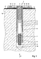
- the internal thread anchor 1 according to the invention shown in the drawing has a diameter-stepped shank 2 with an external thread 3 at an end designated here as the front and is hollow at an opposite end, designated here as a rear end, where it has an internal thread 4 for fastening a not shown Object.
- a cone nut 5 is screwed, which can be generally understood as an expansion body.
- an expansion sleeve 6 is arranged on the shaft 2, which is subdivided by longitudinal slots in expansion tongues 7, which can be pressed out by drawing in the cone nut 5 between the expansion tongues 7 to the outside, i. are spreadable.
- the expansion sleeve 6 is supported axially via a spacer sleeve 8 on an annular shoulder 9 of the shaft 2.
- the internal thread anchor 1 has a hole-disc-shaped sealing flange 10, which is connected by shrinking, pressing, soldering or welding rigidly connected to the rear end of the shaft 2 and hermetically sealed.
- the sealing flange 10 is flush with the rear end of the shaft 2.
- the sealing flange 10 is thin, in the illustrated embodiment, its thickness is less than 1/3 of a diameter of the shaft 2 at the rear end.
- An upper side 11 and a lower side 12 of the sealing flange 10 are flat and mutually parallel surfaces. As the bottom 12, the side of the sealing flange 10 is referred to, which points in the direction of the internal thread anchor 1.
- a disk-shaped sliding disk 13 is arranged, for example made of plastic on the shaft 2, which has a smaller diameter than the sealing flange 10.
- the sealing flange 10 Radially outside the sliding disk 13, the sealing flange 10 has on its underside 12 a circumferential recess 14, which encloses the internal thread anchor 1 and its shaft 2 in the circumferential direction without interruption.
- the recess 14 is designed as a circular, concentric and the sliding disk 12 enclosing groove with a flat rectangular cross-section. Equidistant at three points open filling openings 15 in the recess 14.
- the filling openings 15 are holes that emanate from the top 11 of the sealing flange 10 and open into the recess 14 on the bottom 12 of the sealing flange 10.
- the internal thread anchor 1 is intended for anchoring in an anchor base 16, for example made of concrete, which has a liquid-tight layer 17 on its surface.
- the liquid-tight layer 17 may be, for example, a paint, a resin layer, bitumen, a plastic film or stainless steel sheet.
- an anchor hole 18 is drilled through the liquid-tight layer 17 in the anchor base 16 and the internal thread anchor 1 is introduced into the anchor hole 18, so that the sliding disk 13 rest on the liquid-tight layer 17 and the sealing flange 10 on the sliding disk 13.
- the external thread 3 of its shaft 2 is screwed into the cone nut 5 and the cone nut 5 is pulled between the expansion tongues 7 of the expansion sleeve 6.
- the cone nut 5 spreads the expansion sleeve 6 and its expansion tongues 7, so that the internal thread anchor 1 is anchored in the anchorage 16.
- a screw not shown, are screwed into the internal thread 4, so that a screw head is seated on the rear end of the internal thread anchor 1 and can be used for applying a torque.
- the screw is then unscrewed again.
- the sliding washer 13 between the sealing flange 10 and the liquid-tight layer 17 reduces friction between the sealing flange 10 and the liquid-tight layer 17 and thereby reduces a torque required for rotating the internal thread anchor 1.
- the sliding disc 13 avoids damage to the liquid-tight layer 17 by the co-rotating with the internal thread anchor 1 sealing flange 10, for example, cutting an edge of the sealing flange 10 in the liquid-tight layer 17.
- a flowable, hardening sealant 19 through the filling openings 15 in the recess 14 is introduced on the underside 12 of the sealing flange 10.
- the sealing compound 19 is distributed in the circumferential direction so that it surrounds the internal thread anchor 1 outside the sliding disk 13 in the circumferential direction without interruption and seals between the sealing flange 10 and the liquid-tight layer 17. In this way, the liquid-tight layer 17 is sealed at the point where it is penetrated by the internal thread anchor 1.
- an item, not shown can be attached.
- the sealant 19 may as in FIG. 1 can be seen, between the sealing flange 10 and the liquid-tight layer 17 radially inwardly and / or outwardly from the recess 14 exit, so that reliable a good seal is achieved. Is the sealant 19 can be seen on the outer edge of the sealing flange 10, visually check whether it is closed in the circumferential direction and has no interruption.
Landscapes
- Engineering & Computer Science (AREA)
- General Engineering & Computer Science (AREA)
- Mechanical Engineering (AREA)
- Joining Of Building Structures In Genera (AREA)
Applications Claiming Priority (1)
| Application Number | Priority Date | Filing Date | Title |
|---|---|---|---|
| DE102014106662.6A DE102014106662A1 (de) | 2014-05-12 | 2014-05-12 | Innengewindenanker |
Publications (1)
| Publication Number | Publication Date |
|---|---|
| EP2944833A1 true EP2944833A1 (fr) | 2015-11-18 |
Family
ID=53276047
Family Applications (1)
| Application Number | Title | Priority Date | Filing Date |
|---|---|---|---|
| EP15401035.9A Withdrawn EP2944833A1 (fr) | 2014-05-12 | 2015-05-04 | Cheville à filetage intérieur |
Country Status (2)
| Country | Link |
|---|---|
| EP (1) | EP2944833A1 (fr) |
| DE (1) | DE102014106662A1 (fr) |
Cited By (1)
| Publication number | Priority date | Publication date | Assignee | Title |
|---|---|---|---|---|
| EP4350180A4 (fr) * | 2021-06-01 | 2024-09-25 | Topura Co., Ltd. | Fixation filetée, et élément d'ajout de fonction de fixation filetée |
Families Citing this family (1)
| Publication number | Priority date | Publication date | Assignee | Title |
|---|---|---|---|---|
| EP3189901A1 (fr) | 2016-01-11 | 2017-07-12 | HILTI Aktiengesellschaft | Injecteur destine a remplir un espace annulaire autour d'un boulon d'ancrage |
Citations (9)
| Publication number | Priority date | Publication date | Assignee | Title |
|---|---|---|---|---|
| GB190902960A (en) * | 1909-02-08 | 1909-09-23 | Sydney Smith | Improvements in Screw Nuts. |
| US1505580A (en) * | 1922-10-23 | 1924-08-19 | Adelbert E Bronson | Nut |
| US2462023A (en) * | 1945-11-02 | 1949-02-15 | Radio Frequency Lab Inc | Seal nut |
| FR2549915A1 (fr) * | 1983-07-29 | 1985-02-01 | Materiel & Equipments Tec | Perfectionnements aux systemes de vissage comprenant un ecrou a embase et aux composants de ces systemes |
| EP1772635A2 (fr) * | 2005-10-04 | 2007-04-11 | Böllhoff Verbindungstechnik GmbH | Raccord et procédure de sa fixation sur une surface |
| DE102006000224A1 (de) | 2006-05-12 | 2007-11-15 | Hilti Ag | Abdichtelement für ein in einem Untergrund verankertes Befestigungselement |
| DE202011004431U1 (de) * | 2011-03-25 | 2011-06-28 | Spiggo GmbH, 87527 | Isolierdübel |
| US8210785B1 (en) * | 2006-12-06 | 2012-07-03 | Gager Dennis J | Decorative cap and nut for toilet base |
| US20150114544A1 (en) * | 2013-10-31 | 2015-04-30 | Caterpillar Inc. | Mounting structure and method of attaching mounting structure to surface |
-
2014
- 2014-05-12 DE DE102014106662.6A patent/DE102014106662A1/de not_active Withdrawn
-
2015
- 2015-05-04 EP EP15401035.9A patent/EP2944833A1/fr not_active Withdrawn
Patent Citations (9)
| Publication number | Priority date | Publication date | Assignee | Title |
|---|---|---|---|---|
| GB190902960A (en) * | 1909-02-08 | 1909-09-23 | Sydney Smith | Improvements in Screw Nuts. |
| US1505580A (en) * | 1922-10-23 | 1924-08-19 | Adelbert E Bronson | Nut |
| US2462023A (en) * | 1945-11-02 | 1949-02-15 | Radio Frequency Lab Inc | Seal nut |
| FR2549915A1 (fr) * | 1983-07-29 | 1985-02-01 | Materiel & Equipments Tec | Perfectionnements aux systemes de vissage comprenant un ecrou a embase et aux composants de ces systemes |
| EP1772635A2 (fr) * | 2005-10-04 | 2007-04-11 | Böllhoff Verbindungstechnik GmbH | Raccord et procédure de sa fixation sur une surface |
| DE102006000224A1 (de) | 2006-05-12 | 2007-11-15 | Hilti Ag | Abdichtelement für ein in einem Untergrund verankertes Befestigungselement |
| US8210785B1 (en) * | 2006-12-06 | 2012-07-03 | Gager Dennis J | Decorative cap and nut for toilet base |
| DE202011004431U1 (de) * | 2011-03-25 | 2011-06-28 | Spiggo GmbH, 87527 | Isolierdübel |
| US20150114544A1 (en) * | 2013-10-31 | 2015-04-30 | Caterpillar Inc. | Mounting structure and method of attaching mounting structure to surface |
Cited By (1)
| Publication number | Priority date | Publication date | Assignee | Title |
|---|---|---|---|---|
| EP4350180A4 (fr) * | 2021-06-01 | 2024-09-25 | Topura Co., Ltd. | Fixation filetée, et élément d'ajout de fonction de fixation filetée |
Also Published As
| Publication number | Publication date |
|---|---|
| DE102014106662A1 (de) | 2015-11-12 |
Similar Documents
| Publication | Publication Date | Title |
|---|---|---|
| DE102004051739B4 (de) | Verschlussdeckel für eine Befestigungsanordnung | |
| DE1802770A1 (de) | Verfahren zum Verankern eines Befestigungselementes in einer Wand od.dgl. und zugehoeriges Befestigungselement | |
| DE19818739A1 (de) | Befestigungselement zum nachträglichen Bewehrungsanschluß, insbesondere für Erdbebensicherung | |
| DE2510550A1 (de) | Befestigungseinrichtung fuer gewindebolzen | |
| DE2838466A1 (de) | Verfahren zum kraftschluessigen verbinden von bauteilen mit mindestens einer ankerhuelse | |
| EP2944833A1 (fr) | Cheville à filetage intérieur | |
| EP1783379B1 (fr) | Dispositif d'ancrage expansible | |
| DE10305911A1 (de) | Formschlüssig setzbarer Hinterschneid-Anker | |
| EP3189901A1 (fr) | Injecteur destine a remplir un espace annulaire autour d'un boulon d'ancrage | |
| DE19520130A1 (de) | Formschlüssig setzbarer Hinterschnitt-Anker | |
| DE2354185A1 (de) | Verankerungsbuchse | |
| EP2495378A2 (fr) | Système de fixation et procédé d'étanchéification sur une façade ou un toit plat | |
| DE102016110159A1 (de) | Anker | |
| AT513720B1 (de) | Befestigungselement | |
| EP2977623B1 (fr) | Ancre | |
| DE3208266C2 (fr) | ||
| DE202005006769U1 (de) | Formschlüssig setzbarer Bolzenanker | |
| DE3901013A1 (de) | Injektionspacker fuer das einpressen von fluessigen stoffen in rissige bauwerkskoerper mit einem ventil | |
| EP1690992B1 (fr) | Ancre d'attache et son utilisation | |
| DE102004052184A1 (de) | Nageldübel | |
| DE2111782A1 (de) | Ankerbolzen und Verfahren fuer deren Installierung | |
| DE7630026U1 (de) | Anschluss- und abdichtungseinrichtung zur ausbesserung von unerwuenschten hohlraeumen in vorzugsweise mauerwerk oder beton | |
| DE3737462A1 (de) | Stopfen fuer die gebirgsverfestigung | |
| DE4315575A1 (de) | Vorrichtung zur Injektion von fließfähigen Materialien in Mauerwerke, Holz o. dgl. | |
| DE20218372U1 (de) | Zentrierhilfe zur Injektionsbefestigung |
Legal Events
| Date | Code | Title | Description |
|---|---|---|---|
| PUAI | Public reference made under article 153(3) epc to a published international application that has entered the european phase |
Free format text: ORIGINAL CODE: 0009012 |
|
| AK | Designated contracting states |
Kind code of ref document: A1 Designated state(s): AL AT BE BG CH CY CZ DE DK EE ES FI FR GB GR HR HU IE IS IT LI LT LU LV MC MK MT NL NO PL PT RO RS SE SI SK SM TR |
|
| AX | Request for extension of the european patent |
Extension state: BA ME |
|
| RIN1 | Information on inventor provided before grant (corrected) |
Inventor name: BAEUERLE, RALF Inventor name: WETZEL, BERND |
|
| 17P | Request for examination filed |
Effective date: 20160425 |
|
| RBV | Designated contracting states (corrected) |
Designated state(s): AL AT BE BG CH CY CZ DE DK EE ES FI FR GB GR HR HU IE IS IT LI LT LU LV MC MK MT NL NO PL PT RO RS SE SI SK SM TR |
|
| 17Q | First examination report despatched |
Effective date: 20161010 |
|
| RIC1 | Information provided on ipc code assigned before grant |
Ipc: F16B 33/00 20060101AFI20170726BHEP Ipc: F16B 17/00 20060101ALN20170726BHEP Ipc: F16B 37/12 20060101ALI20170726BHEP |
|
| GRAP | Despatch of communication of intention to grant a patent |
Free format text: ORIGINAL CODE: EPIDOSNIGR1 |
|
| RIC1 | Information provided on ipc code assigned before grant |
Ipc: F16B 37/12 20060101ALI20170831BHEP Ipc: F16B 17/00 20060101ALN20170831BHEP Ipc: F16B 33/00 20060101AFI20170831BHEP |
|
| INTG | Intention to grant announced |
Effective date: 20170920 |
|
| STAA | Information on the status of an ep patent application or granted ep patent |
Free format text: STATUS: THE APPLICATION IS DEEMED TO BE WITHDRAWN |
|
| 18D | Application deemed to be withdrawn |
Effective date: 20180131 |