EP2944903B1 - Ofen zum Brennen von keramischen Formlingen - Google Patents
Ofen zum Brennen von keramischen Formlingen Download PDFInfo
- Publication number
- EP2944903B1 EP2944903B1 EP14001672.6A EP14001672A EP2944903B1 EP 2944903 B1 EP2944903 B1 EP 2944903B1 EP 14001672 A EP14001672 A EP 14001672A EP 2944903 B1 EP2944903 B1 EP 2944903B1
- Authority
- EP
- European Patent Office
- Prior art keywords
- kiln
- wall
- air
- region
- heating
- Prior art date
- Legal status (The legal status is an assumption and is not a legal conclusion. Google has not performed a legal analysis and makes no representation as to the accuracy of the status listed.)
- Active
Links
Images
Classifications
-
- F—MECHANICAL ENGINEERING; LIGHTING; HEATING; WEAPONS; BLASTING
- F27—FURNACES; KILNS; OVENS; RETORTS
- F27B—FURNACES, KILNS, OVENS OR RETORTS IN GENERAL; OPEN SINTERING OR LIKE APPARATUS
- F27B9/00—Furnaces through which the charge is moved mechanically, e.g. of tunnel type; Similar furnaces in which the charge moves by gravity
- F27B9/02—Furnaces through which the charge is moved mechanically, e.g. of tunnel type; Similar furnaces in which the charge moves by gravity of multiple-track type; of multiple-chamber type; Combinations of furnaces
- F27B9/021—Furnaces through which the charge is moved mechanically, e.g. of tunnel type; Similar furnaces in which the charge moves by gravity of multiple-track type; of multiple-chamber type; Combinations of furnaces having two or more parallel tracks
- F27B9/022—With two tracks moving in opposite directions
-
- F—MECHANICAL ENGINEERING; LIGHTING; HEATING; WEAPONS; BLASTING
- F27—FURNACES; KILNS; OVENS; RETORTS
- F27B—FURNACES, KILNS, OVENS OR RETORTS IN GENERAL; OPEN SINTERING OR LIKE APPARATUS
- F27B17/00—Furnaces of a kind not covered by any of groups F27B1/00 - F27B15/00
- F27B17/0016—Chamber type furnaces
- F27B17/0041—Chamber type furnaces specially adapted for burning bricks or pottery
-
- F—MECHANICAL ENGINEERING; LIGHTING; HEATING; WEAPONS; BLASTING
- F27—FURNACES; KILNS; OVENS; RETORTS
- F27B—FURNACES, KILNS, OVENS OR RETORTS IN GENERAL; OPEN SINTERING OR LIKE APPARATUS
- F27B9/00—Furnaces through which the charge is moved mechanically, e.g. of tunnel type; Similar furnaces in which the charge moves by gravity
- F27B9/14—Furnaces through which the charge is moved mechanically, e.g. of tunnel type; Similar furnaces in which the charge moves by gravity characterised by the path of the charge during treatment; characterised by the means by which the charge is moved during treatment
- F27B9/20—Furnaces through which the charge is moved mechanically, e.g. of tunnel type; Similar furnaces in which the charge moves by gravity characterised by the path of the charge during treatment; characterised by the means by which the charge is moved during treatment the charge moving in a substantially straight path
- F27B9/22—Furnaces through which the charge is moved mechanically, e.g. of tunnel type; Similar furnaces in which the charge moves by gravity characterised by the path of the charge during treatment; characterised by the means by which the charge is moved during treatment the charge moving in a substantially straight path on rails, e.g. under the action of scrapers or pushers
-
- F—MECHANICAL ENGINEERING; LIGHTING; HEATING; WEAPONS; BLASTING
- F27—FURNACES; KILNS; OVENS; RETORTS
- F27B—FURNACES, KILNS, OVENS OR RETORTS IN GENERAL; OPEN SINTERING OR LIKE APPARATUS
- F27B9/00—Furnaces through which the charge is moved mechanically, e.g. of tunnel type; Similar furnaces in which the charge moves by gravity
- F27B9/14—Furnaces through which the charge is moved mechanically, e.g. of tunnel type; Similar furnaces in which the charge moves by gravity characterised by the path of the charge during treatment; characterised by the means by which the charge is moved during treatment
- F27B9/20—Furnaces through which the charge is moved mechanically, e.g. of tunnel type; Similar furnaces in which the charge moves by gravity characterised by the path of the charge during treatment; characterised by the means by which the charge is moved during treatment the charge moving in a substantially straight path
- F27B9/26—Furnaces through which the charge is moved mechanically, e.g. of tunnel type; Similar furnaces in which the charge moves by gravity characterised by the path of the charge during treatment; characterised by the means by which the charge is moved during treatment the charge moving in a substantially straight path on or in trucks, sleds, or containers
-
- Y—GENERAL TAGGING OF NEW TECHNOLOGICAL DEVELOPMENTS; GENERAL TAGGING OF CROSS-SECTIONAL TECHNOLOGIES SPANNING OVER SEVERAL SECTIONS OF THE IPC; TECHNICAL SUBJECTS COVERED BY FORMER USPC CROSS-REFERENCE ART COLLECTIONS [XRACs] AND DIGESTS
- Y02—TECHNOLOGIES OR APPLICATIONS FOR MITIGATION OR ADAPTATION AGAINST CLIMATE CHANGE
- Y02P—CLIMATE CHANGE MITIGATION TECHNOLOGIES IN THE PRODUCTION OR PROCESSING OF GOODS
- Y02P40/00—Technologies relating to the processing of minerals
- Y02P40/60—Production of ceramic materials or ceramic elements, e.g. substitution of clay or shale by alternative raw materials, e.g. ashes
Definitions
- the invention relates to a furnace for firing ceramic moldings, in particular bricks, with a plurality of trains comprising a plurality of kiln cars, which can be moved parallel to one another and along a longitudinal furnace path, on which the moldings are to be arranged, the furnace path being a firing zone for heating the Has moldings and wherein juxtaposed trains can be moved in opposite directions without a reversal of direction through a firing zone, at least one fan being provided.
- An oven of this kind is made of DE 10 2011 112 838 A1 known.
- the furnace is loaded on one side of the furnace line, while on the opposite other side of the furnace line, the respective trains are loaded with moldings for transport through the furnace along the furnace line in the opposite direction. It takes place in the respective trains no reversal of direction takes place, so that the moldings move through the firing zone on their respective furnace trains and are removed from the furnace section at the opposite end of the furnace section in terms of their equipment. Due to the moldings moving past each other on both sides of the firing zone, the moldings already leaving the firing zone are heated up as cold stock before they reach the firing zone. By dispensing with a change of direction in the firing zone, the available space of the furnace is optimally used.
- the moldings are heated in the firing zone by fuel elements arranged in a longitudinal lane (main tunnel) between the trains.
- the heating energy used can be brought directly to the moldings, which leads to increased efficiency in the firing zone and consequently to a reduced use of energy.
- the heating of the bricks or similar moldings can be carried out directly and evenly distributed over their height in the trim.
- a tunnel kiln for heat treatment of products with two parallel treatment channels is known, through which the products are passed in two mutually opposing flows, the channels being divided into a heating zone, a burning zone and a cooling zone, and the heat given off in the cooling zone of each channel is made usable in the heating zone of the other channel.
- ventilation means are provided which, in countercurrent to the product flows, suck the air out of the heating zone of each channel and convey it into the cooling zone of the other channel.
- a tunnel kiln is known in which two product flows are guided in opposite directions in the tunnel and where in turn heating and cooling zones are formed.
- the air is circulated through a cross circulation transverse to the direction of conveyance of the product flows. This means that no more than two product streams can be treated in the tunnel kiln.
- Similar tunnel kilns are from each of US 1 720 550 , US-1,658,332 or US 1,653,174 known.
- This generic oven has considerable advantages over conventional other ovens, but should be further improved.
- the furnace of the type mentioned at the outset is characterized in that a furnace wall which delimits a train laterally has a heating device is heated and the opposite furnace wall, which limits a train laterally, can be cooled by a cooling device.
- This provides a furnace in which the respective furnace walls which laterally delimit the trains depend on whether the train which is adjacent to this furnace wall during its transport through the furnace section carries a cold stock of moldings or a hot stock of moldings the heating device can be heated or is to be cooled when the moldings are hot.
- the temperature gradient to the respective molded article can thus be significantly improved via the respective heating device or via the respective cooling device, so that the furnace walls which laterally limit the trains serve as wall temperature stores or also as cooling temperature stores and can therefore act on the trains on moldings, each of which have no direct neighbors in the transverse row to give off heat or to give up heat there.
- the heating device is preferably designed as a hot air device, and the cooling device can also be designed as a cooling air device.
- heating rods are also possible as heating devices.
- other cooling units can also be used. It is also possible to directly temper the corresponding furnace walls by means of appropriate heating coils or cooling coils.
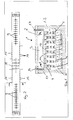
- the oven which has an oven section 2 with a combustion zone, a circulation channel 3 and cooling and heating zones, is generally numbered 1.
- a total of twelve trains 4, 5 are shown in the furnace 1, one train 4 being moved in one direction into the plane of the drawing and train 5 being moved in the opposite direction, that is to say out of the plane of the drawing.
- a train 4, which is fitted with moldings 6, just like the train 5, can have a cold stock, whereas the train 5 has a warm, that is to say burned stock of moldings 6, so that cold and warm trains 4 alternately side by side. 5 are transported with the exception of the first train on the far left in the drawing sheets and the right last train, the first train 4 being a cold one Has a trim and the last right trim has a warm trim.
- the warm trimmings can therefore only give off its heat on the right outside to the trimmings of this train, which in turn are cold trimmings.
- this train can emit its heat to the air 8, which is drawn in by the fan 9, which is a radial compressor in the exemplary embodiment shown, so that forced convection takes place within the furnace and along the furnace section via the radial fan 9.
- a wall 10 is provided below the circulation channel 3, on which air guiding devices 11 are provided, which prevent air 8 from being conveyed along the wall 10 bypassing the molded articles 6.
- a heating device 16 is provided for heating the side furnace wall 1.1 and a cooling device 17 for cooling the side furnace wall 1.2 subordinate.
- the heating device 16 is adjacent to the cold stock of the train 4 and the cooling device 17 to the hot stock of moldings 6 in the Fig. 1 right turn. Forced convection can be performed using the fans.
Landscapes
- Engineering & Computer Science (AREA)
- Mechanical Engineering (AREA)
- General Engineering & Computer Science (AREA)
- Tunnel Furnaces (AREA)
Description
- Die Erfindung bezieht sich auf einen Ofen zum Brennen von keramischen Formlingen, insbesondere von Ziegeln mit einer Mehrzahl von parallel zueinander und entlang einer längs verlaufenden Ofenstrecke bewegbaren, mehrere Ofenwagen umfassenden Zügen, auf denen die Formlinge anzuordnen sind, wobei die Ofenstrecke eine Brennzone zur Erhitzung der Formlinge aufweist und wobei nebeneinander angeordnete Züge in entgegengesetzte Richtungen bewegbar sind ohne eine Richtungsumkehr durch eine Brennzone, wobei zumindest ein Lüfter vorgesehen ist.
- Ein Ofen dieser Art ist aus der
DE 10 2011 112 838 A1 bekannt. Bei diesem Ofen erfolgt die Bestückung des Ofens auf der einen Seite der Ofenstrecke, während auf der gegenüberliegenden anderen Seite der Ofenstrecke eine Bestückung der jeweiligen Züge mit Formlingen für einen Transport durch den Ofen entlang der Ofenstrecke in die entgegengesetzte Richtung erfolgt. Dabei findet in den jeweiligen Zügen keine Richtungsumkehr statt, so dass sich die Formlinge auf ihren jeweiligen Ofenzügen durch die Brennzone hindurch bewegen und jeweils am bezüglich ihrer Bestückung entgegengesetzten Ende der Ofenstrecke dieser entnommen werden. Durch die auf beiden Seiten der Brennzone jeweils aneinander vorbei bewegten Formlinge werden von den bereits die Brennzone verlassenden Formlinge andere als Kaltbesatz aufgeheizt, bevor sie in die Brennzone gelangen. Durch den Verzicht auf eine Richtungsumkehr in der Brennzone wird der zur Verfügung stehende Bauraum des Ofens optimal ausgenutzt. Die Formlinge werden in der Brennzone durch in einer Längsgasse (Haupttunnel) zwischen den Zügen angeordnete Brennelemente erhitzt. Hierdurch kann die verwendete Heizenergie direkt zu den Formlingen gebracht werden, was zu einer erhöhten Effizienz in der Brennzone und mithin zu einem verringerten Energieeinsatz führt. Die Erhitzung der Ziegel oder dergleichen Formlinge kann unmittelbar und gleichmäßig über deren Aufbauhöhe im Besatz verteilt erfolgen. - Aus der
DE 30 42 708 A ist ein Tunnelofen zur Wärmebehandlung von Produkten mit zwei parallelen Behandlungskanälen bekannt, durch die hindurch die Produkte in zwei zueinander gegenläufigen Strömen geführt werden, wobei sich die Kanäle in eine Aufheizzone, eine Brennzone und eine Kühlzone unterteilen und wobei die in der Kühlzone jedes Kanals abgegebene Wärme in der Aufheizzone des anderen Kanals nutzbar gemacht wird. Dazu sind Ventilationsmittel vorgesehen, welche im Gegenstrom zu den Produktströmen die Luft aus der Aufheizzone eines jeden Kanals absaugen und in die Kühlzone des anderen Kanals einfördern. Damit lassen sich jedoch nicht mehr als zwei Produktstromzüge behandeln. - Aus der
WO 01/71265 A1 US 1 720 550 ,US-1 658 332 oderUS 1 653 174 bekannt. - Es ist Aufgabe der vorliegenden Erfindung, einen Ofen der eingangs genannten Art weiter zu optimieren.
- Zur Lösung dieser Aufgabe zeichnet sich der Ofen der eingangs genannten Art durch die im Patentanspruch 1 angegebenen Merkmale aus. Hinsichtlich vorteilhafter Ausgestaltung wird auf die Ansprüche 2 bis 10 verwiesen.
- Dieser gattungsgemäße Ofen hat gegenüber herkömmlichen anderen Öfen erhebliche Vorteile, soll jedoch weiter verbessert werden.
- Es ist daher Aufgabe der vorliegenden Erfindung, einen Ofen der eingangs genannten Art weiter zu optimieren.
- Zur Lösung dieser Aufgabe zeichnet sich der Ofen der eingangs genannten Art dadurch aus, dass eine einen Zug seitliche begrenzende Ofenwand über eine Heizvorrichtung beheizbar ist und die gegenüberliegende, einen Zug seitliche begrenzende Ofenwand über eine Kühlvorrichtung kühlbar ist.
- Damit ist ein Ofen zur Verfügung gestellt, bei dem die jeweilige die Züge seitlich begrenzenden Ofenwände je nach dem, ob der Zug, der dieser Ofenwand während ihres Transportes durch die Ofenstrecke benachbart ist, einen kalten Besatz an Formlingen trägt oder einen heißen Besatz an Formlingen über die Heizvorrichtung beheizt werden kann oder bei einem heißen Besatz an Formlingen zu kühlen ist.
- Damit kann über die jeweilige Heizvorrichtung bzw. über die jeweilige Kühlvorrichtung das Temperaturgefälle wesentlich verbessert werden zu dem jeweiligen Formling, so dass die seitlich die Züge begrenzende Ofenwände als Wandtemperaturspeicher oder aber auch als Kühltemperaturspeicher dienen und mithin auf die Züge an Formlingen einwirken können, die jeweils in der Querreihe keine direkten Nachbarn haben, um dort hin Wärme abzugeben bzw. Wärme aufzugeben.
- Die Heizvorrichtung ist bevorzugterweise als Heißluftvorrichtung ausgebildet, und die Kühlvorrichtung kann ebenfalls als Kühlluftvorrichtung ausgebildet sein. Es sind selbstverständlich auch Heizstäbe als Heizvorrichtungen möglich. Des Weiteren können auch andere Kühlaggregate zum Einsatz kommen. Ebenfalls ist es möglich, die entsprechenden Ofenwände direkt durch entsprechende Heizschlangen oder Kühlschlangen direkt zu temperieren.
- Weitere vorteilhafte Ausgestaltungen ergeben sich aus weiteren Unteransprüchen, der nachfolgenden Beschreibung und der Zeichnung. In der Zeichnung zeigen:
- Fig. 1
- in einer schematischen Querschnittsdarstellung ein Ausführungsbeispiel eines Ofens nach der Erfindung (gemäß Schnittlinie A-A) in
Fig. 2 , - Fig. 2
- eine Draufsicht auf den Ofen gemäß dem Ausführungsbeispiel nach
Fig. 1 . - In der Zeichnung sind grundsätzlich übereinstimmende Teile mit übereinstimmenden Bezugsziffern versehen.
- Allgemein mit 1 ist der Ofen beziffert, der eine Ofenstrecke 2 aufweist mit einer Brennzone, einem Umwälzkanal 3 und Kühl- und Aufwärmzonen. In dem Ofen 1 sind in den Ausführungsbeispielen insgesamt zwölf Züge 4, 5 dargestellt, wobei jeweils ein Zug 4 in eine Richtung in die Zeichnungsebene hinein bewegt wird und der Zug 5 in entgegengesetzte Richtung, also aus der Zeichnungsebene heraus bewegt wird.
- Ein Zug 4, der mit Formlingen 6 bestückt ist, genauso wie der Zug 5, kann einen kalten Besatz haben, wogegen der Zug 5 einen warmen, also schon gebrannten Besatz an Formlingen 6 hat, so dass jeweils abwechselnd nebeneinander kalte und warme Züge 4, 5 transportiert werden mit Ausnahme des ersten Zuges ganz links in den Zeichnungsblättern und dem rechten letzten Zug, wobei der erste Zug 4 einen kalten Besatz hat und der letzte rechte Besatz einen warmen Besatz hat. Der warme Besatz kann daher nur an der rechten Außenseite seine Wärme an den links benachbarten Besatz dieses Zuges abgeben kann, der wiederum ein kalter Besatz ist. In dem gezeigten Ausführungsbeispiel kann dieser Zug seine Wärme an die Luft 8 abgeben, die von dem Lüfter 9, der in dem gezeigten Ausführungsbeispiel ein Radialverdichter ist, angesaugt wird, so dass über den Radialventilator 9 eine Zwangskonvektion innerhalb des Ofens und entlang der Ofenstrecke stattfindet.
- Unterhalb des Umwälzkanals 3 ist eine Wandung 10 vorgesehen, an der Luftleitvorrichtungen 11 vorgesehen sind, die verhindern, dass Luft 8 unter Umgehung der Formlinge 6 an der Wandung 10 entlanggefördert wird.
- Wie im Einzelnen näher
Fig. 1 zu entnehmen ist, ist zur Beheizung der seitlichen Ofenwand 1.1 eine Heizvorrichtung 16 vorgesehen und zum Kühlen der seitlichen Ofenwand 1.2 eine Kühlvorrichtung 17. Die Heizvorrichtung 16 ist in Transportrichtung der jeweiligen Züge den Brennern 18 der Brennzone vorgeordnet und die Kühlvorrichtung 17 den Brennern 18 der Brennzone nachgeordnet. Somit ist die Heizvorrichtung 16 dem kalten Besatz des Zuges 4 benachbart und die Kühlvorrichtung 17 dem heißen Besatz von Formlingen 6 des in derFig. 1 rechten Zuges. Über die Ventilatoren kann eine Zwangskonvektion durchgeführt werden.
Claims (10)
- Ofen zum Brennen von keramischen Formlingen, insbesondere von Ziegeln mit einer Mehrzahl von parallel zueinander und entlang einer längs verlaufenden Ofenstrecke bewegbaren, mehrere Ofenwagen umfassenden Zügen, auf denen die Formlinge anzuordnen sind, wobei die Ofenstrecke eine Brennzone zur Erhitzung der Formlinge aufweist, wobei nebeneinander angeordnete Züge in entgegengesetzte Richtungen ohne eine Richtungsumkehr durch die Brennzone bewegbar sind, und wobei zumindest ein Lüfter zur Luftumwälzung vorgesehen ist, wobei eine einen Zug (4, 5) seitlich begrenzende Ofenwand (1.1) über eine Heizvorrichtung (16) beheizbar ist und die gegenüberliegende, einen Zug (4, 5) seitlich begrenzende Ofenwand (1.2) über eine Kühlvorrichtung (17) kühlbar ist, dadurch gekennzeichnet, dass in Wandabschnitten der jeweiligen Ofenwand (1.1, 1.2) mehrere Heizvorrichtungen (16) und mehrere Kühlvorrichtungen (17) mit Abstand zueinander derart vorgesehen sind, dass in einer Ofenwand (1.1, 1.2) vor der Brennzone mehrere Heizvorrichtungen (16) und nach der Brennzone mehrere Kühlvorrichtungen (17) vorgesehen sind.
- Ofen nach Anspruch 1 dadurch gekennzeichnet, dass die Heizvorrichtung (16) als Heißluftvorrichtung ausgebildet ist.
- Ofen nach einem der Ansprüche 1 bis 2 dadurch gekennzeichnet, dass die Kühlvorrichtung (17) als Kühlluftvorrichtung ausgebildet ist.
- Ofen nach einem der Ansprüche 1 bis 3 dadurch gekennzeichnet, dass oberhalb der Formlinge (6) eine Wandung vorgesehen ist mit einer Öffnung, in der ein Axialventilator und/oder ein Radialventilator als Lüfter vorgesehen ist (sind).
- Ofen nach Anspruch 4 dadurch gekennzeichnet, dass oberhalb der Wandung ein Umwälzkanal vorgesehen ist.
- Ofen nach einem der Ansprüche 1 bis 5 dadurch gekennzeichnet, dass in der Ofenstrecke zumindest eine Luftleitvorrichtung vorgesehen ist.
- Ofen nach einem der Ansprüche 4 oder 5 und 6 dadurch gekennzeichnet, dass eine Luftleitvorrichtung unterhalb der Wandung vorgesehen sind.
- Ofen nach Anspruch 6 oder 7 dadurch gekennzeichnet, dass Luftleitvorrichtungen in einen Haupttunnel der Ofenstrecke hineinragen.
- Ofen nach Anspruch 8 dadurch gekennzeichnet, dass mit Abstand zueinander angeordnete Luftleitvorrichtungen unterschiedlich lang ausgebildet sind und unterschiedlich tief in einen Haupttunnel ragen.
- Ofen nach einem der Ansprüche 1 bis 9 dadurch gekennzeichnet, dass der Lüfter in einer Leitung vorgesehen ist, die über gegenüberliegend angeordnete Leitungsanschlüsse mit der Ofenstrecke verbunden ist und über die die Luft derart in den Ofen eingebracht wird, dass sie den Ofen quer zur Ofenstrecke ausgerichtet durchströmt und dem Lüfter zumindest teilweise wieder zugeführt wird.
Priority Applications (1)
| Application Number | Priority Date | Filing Date | Title |
|---|---|---|---|
| EP14001672.6A EP2944903B1 (de) | 2014-05-13 | 2014-05-13 | Ofen zum Brennen von keramischen Formlingen |
Applications Claiming Priority (1)
| Application Number | Priority Date | Filing Date | Title |
|---|---|---|---|
| EP14001672.6A EP2944903B1 (de) | 2014-05-13 | 2014-05-13 | Ofen zum Brennen von keramischen Formlingen |
Publications (2)
| Publication Number | Publication Date |
|---|---|
| EP2944903A1 EP2944903A1 (de) | 2015-11-18 |
| EP2944903B1 true EP2944903B1 (de) | 2020-04-01 |
Family
ID=50731879
Family Applications (1)
| Application Number | Title | Priority Date | Filing Date |
|---|---|---|---|
| EP14001672.6A Active EP2944903B1 (de) | 2014-05-13 | 2014-05-13 | Ofen zum Brennen von keramischen Formlingen |
Country Status (1)
| Country | Link |
|---|---|
| EP (1) | EP2944903B1 (de) |
Family Cites Families (9)
| Publication number | Priority date | Publication date | Assignee | Title |
|---|---|---|---|---|
| US1653174A (en) * | 1927-12-20 | Tunnel kiln | ||
| US1522166A (en) * | 1921-11-28 | 1925-01-06 | American Dressler Tunnel Kilns | Kiln and method of operating same |
| GB228383A (en) * | 1924-03-20 | 1925-02-05 | Koppers Gmbh Heinrich | Improvements in tunnel ovens and kilns |
| US1720550A (en) * | 1925-09-11 | 1929-07-09 | Jr William Lee Hanley | Tunnel kiln |
| US1658332A (en) * | 1925-10-08 | 1928-02-07 | Jr William Lee Hanley | Twin-tunnel kiln |
| US2320172A (en) * | 1939-06-19 | 1943-05-25 | Swindell Dressler Corp | Tunnel kiln |
| DE3042708C2 (de) * | 1980-11-10 | 1986-07-17 | Rudolf 2106 Bendestorf Riedel | Tunnelofen mit zwei parallelen Kanälen |
| WO2001071265A1 (en) * | 2000-03-22 | 2001-09-27 | Anglo American Corporation Of South Africa Limited | Heating solid material in two opposite streams |
| DE102011112838A1 (de) | 2011-09-12 | 2013-03-14 | Keller Hcw Gmbh | Verfahren zum Brennen von keramischen Formlingen und Ofen |
-
2014
- 2014-05-13 EP EP14001672.6A patent/EP2944903B1/de active Active
Non-Patent Citations (1)
| Title |
|---|
| None * |
Also Published As
| Publication number | Publication date |
|---|---|
| EP2944903A1 (de) | 2015-11-18 |
Similar Documents
| Publication | Publication Date | Title |
|---|---|---|
| EP2568244B1 (de) | Verfahren und Vorrichtung zum Brennen von keramischen Formlingen und Ofen | |
| AT508555B1 (de) | Vorrichtung zur wärmebehandlung von blechzuschnitten | |
| EP3358957B1 (de) | Backofen mit kombinierter wärmeübertragung | |
| DE102008014215A1 (de) | Vorrichtung zum Erwärmen von Behältnissen | |
| DE102005029780A1 (de) | Ofenanlage zum Anwärmen von langen Aluminiumsträngen | |
| AT509596A4 (de) | Verfahren zum erwärmen eines formbauteils für ein anschliessendes presshärten sowie durchlaufofen zum bereichsweisen erwärmen eines auf eine vorgegebene temperatur vorgewärmten formbauteils auf eine höhere temperatur | |
| DE102012001742B4 (de) | Vorrichtung zum Erwärmen von Blechwerkstücken für ein nachfolgendes Warmumformen oder Presshärten | |
| DE3783383T2 (de) | Verfahren zur kuehlung von gebrannten produkten in einem ofen. | |
| EP2944905B1 (de) | Ofen zum Brennen von keramischen Formlingen | |
| EP1581677B1 (de) | Heizvorrichtung zum erwärmen eines fadens | |
| DE3042708A1 (de) | Tunnelofen mit zwei parallelen kanaelen | |
| EP2944904B1 (de) | Ofen zum Brennen von keramischen Formlingen | |
| EP2778588B1 (de) | Ofen zum Brennen von keramischen Formlingen | |
| DE3545498C2 (de) | ||
| EP0093877B1 (de) | Vorrichtung zur Wärmebehandlung von stückigem Gut bei hoher Temperatur | |
| EP2501659B1 (de) | Kammerofen zur herstellung von glasschaumplatten oder formkörpern aus glasschaum | |
| DE102015112375A1 (de) | Durchlaufofen und Verfahren zu dessen Betrieb | |
| EP2944903A1 (de) | Ofen zum Brennen von keramischen Formlingen | |
| DE102009019573A1 (de) | Ofen und Verfahren zum Erwärmen wenigstens eines Werkstückes | |
| WO2011101231A1 (de) | Transportvorrichtung für brammen mit mindestens zwei giessmaschinen und mindestens drei fährenelementen | |
| EP2944907B1 (de) | Ofen zum Brennen von keramischen Formlingen | |
| DE3437237C2 (de) | ||
| DE834070C (de) | Gas-, elektrisch-, oel- oder kohlebeheizter Brennofen, insbesondere Tunnelofen | |
| EP2944906A1 (de) | Ofen zum Brennen von keramischen Formlingen | |
| EP2870876B1 (de) | Backofen |
Legal Events
| Date | Code | Title | Description |
|---|---|---|---|
| PUAI | Public reference made under article 153(3) epc to a published international application that has entered the european phase |
Free format text: ORIGINAL CODE: 0009012 |
|
| AK | Designated contracting states |
Kind code of ref document: A1 Designated state(s): AL AT BE BG CH CY CZ DE DK EE ES FI FR GB GR HR HU IE IS IT LI LT LU LV MC MK MT NL NO PL PT RO RS SE SI SK SM TR |
|
| AX | Request for extension of the european patent |
Extension state: BA ME |
|
| 17P | Request for examination filed |
Effective date: 20160315 |
|
| RBV | Designated contracting states (corrected) |
Designated state(s): AL AT BE BG CH CY CZ DE DK EE ES FI FR GB GR HR HU IE IS IT LI LT LU LV MC MK MT NL NO PL PT RO RS SE SI SK SM TR |
|
| STAA | Information on the status of an ep patent application or granted ep patent |
Free format text: STATUS: EXAMINATION IS IN PROGRESS |
|
| 17Q | First examination report despatched |
Effective date: 20180710 |
|
| GRAP | Despatch of communication of intention to grant a patent |
Free format text: ORIGINAL CODE: EPIDOSNIGR1 |
|
| STAA | Information on the status of an ep patent application or granted ep patent |
Free format text: STATUS: GRANT OF PATENT IS INTENDED |
|
| INTG | Intention to grant announced |
Effective date: 20191025 |
|
| GRAS | Grant fee paid |
Free format text: ORIGINAL CODE: EPIDOSNIGR3 |
|
| GRAA | (expected) grant |
Free format text: ORIGINAL CODE: 0009210 |
|
| STAA | Information on the status of an ep patent application or granted ep patent |
Free format text: STATUS: THE PATENT HAS BEEN GRANTED |
|
| AK | Designated contracting states |
Kind code of ref document: B1 Designated state(s): AL AT BE BG CH CY CZ DE DK EE ES FI FR GB GR HR HU IE IS IT LI LT LU LV MC MK MT NL NO PL PT RO RS SE SI SK SM TR |
|
| REG | Reference to a national code |
Ref country code: GB Ref legal event code: FG4D Free format text: NOT ENGLISH |
|
| REG | Reference to a national code |
Ref country code: CH Ref legal event code: EP Ref country code: AT Ref legal event code: REF Ref document number: 1251886 Country of ref document: AT Kind code of ref document: T Effective date: 20200415 |
|
| REG | Reference to a national code |
Ref country code: DE Ref legal event code: R096 Ref document number: 502014013870 Country of ref document: DE |
|
| REG | Reference to a national code |
Ref country code: IE Ref legal event code: FG4D Free format text: LANGUAGE OF EP DOCUMENT: GERMAN |
|
| PG25 | Lapsed in a contracting state [announced via postgrant information from national office to epo] |
Ref country code: BG Free format text: LAPSE BECAUSE OF FAILURE TO SUBMIT A TRANSLATION OF THE DESCRIPTION OR TO PAY THE FEE WITHIN THE PRESCRIBED TIME-LIMIT Effective date: 20200701 |
|
| REG | Reference to a national code |
Ref country code: NL Ref legal event code: MP Effective date: 20200401 |
|
| REG | Reference to a national code |
Ref country code: GR Ref legal event code: EP Ref document number: 20200401791 Country of ref document: GR Effective date: 20200916 |
|
| REG | Reference to a national code |
Ref country code: LT Ref legal event code: MG4D |
|
| PG25 | Lapsed in a contracting state [announced via postgrant information from national office to epo] |
Ref country code: LT Free format text: LAPSE BECAUSE OF FAILURE TO SUBMIT A TRANSLATION OF THE DESCRIPTION OR TO PAY THE FEE WITHIN THE PRESCRIBED TIME-LIMIT Effective date: 20200401 Ref country code: CZ Free format text: LAPSE BECAUSE OF FAILURE TO SUBMIT A TRANSLATION OF THE DESCRIPTION OR TO PAY THE FEE WITHIN THE PRESCRIBED TIME-LIMIT Effective date: 20200401 Ref country code: NL Free format text: LAPSE BECAUSE OF FAILURE TO SUBMIT A TRANSLATION OF THE DESCRIPTION OR TO PAY THE FEE WITHIN THE PRESCRIBED TIME-LIMIT Effective date: 20200401 Ref country code: PT Free format text: LAPSE BECAUSE OF FAILURE TO SUBMIT A TRANSLATION OF THE DESCRIPTION OR TO PAY THE FEE WITHIN THE PRESCRIBED TIME-LIMIT Effective date: 20200817 Ref country code: FI Free format text: LAPSE BECAUSE OF FAILURE TO SUBMIT A TRANSLATION OF THE DESCRIPTION OR TO PAY THE FEE WITHIN THE PRESCRIBED TIME-LIMIT Effective date: 20200401 Ref country code: IS Free format text: LAPSE BECAUSE OF FAILURE TO SUBMIT A TRANSLATION OF THE DESCRIPTION OR TO PAY THE FEE WITHIN THE PRESCRIBED TIME-LIMIT Effective date: 20200801 Ref country code: SE Free format text: LAPSE BECAUSE OF FAILURE TO SUBMIT A TRANSLATION OF THE DESCRIPTION OR TO PAY THE FEE WITHIN THE PRESCRIBED TIME-LIMIT Effective date: 20200401 Ref country code: NO Free format text: LAPSE BECAUSE OF FAILURE TO SUBMIT A TRANSLATION OF THE DESCRIPTION OR TO PAY THE FEE WITHIN THE PRESCRIBED TIME-LIMIT Effective date: 20200701 |
|
| PG25 | Lapsed in a contracting state [announced via postgrant information from national office to epo] |
Ref country code: RS Free format text: LAPSE BECAUSE OF FAILURE TO SUBMIT A TRANSLATION OF THE DESCRIPTION OR TO PAY THE FEE WITHIN THE PRESCRIBED TIME-LIMIT Effective date: 20200401 Ref country code: HR Free format text: LAPSE BECAUSE OF FAILURE TO SUBMIT A TRANSLATION OF THE DESCRIPTION OR TO PAY THE FEE WITHIN THE PRESCRIBED TIME-LIMIT Effective date: 20200401 Ref country code: LV Free format text: LAPSE BECAUSE OF FAILURE TO SUBMIT A TRANSLATION OF THE DESCRIPTION OR TO PAY THE FEE WITHIN THE PRESCRIBED TIME-LIMIT Effective date: 20200401 |
|
| PG25 | Lapsed in a contracting state [announced via postgrant information from national office to epo] |
Ref country code: AL Free format text: LAPSE BECAUSE OF FAILURE TO SUBMIT A TRANSLATION OF THE DESCRIPTION OR TO PAY THE FEE WITHIN THE PRESCRIBED TIME-LIMIT Effective date: 20200401 |
|
| REG | Reference to a national code |
Ref country code: DE Ref legal event code: R097 Ref document number: 502014013870 Country of ref document: DE |
|
| PG25 | Lapsed in a contracting state [announced via postgrant information from national office to epo] |
Ref country code: SM Free format text: LAPSE BECAUSE OF FAILURE TO SUBMIT A TRANSLATION OF THE DESCRIPTION OR TO PAY THE FEE WITHIN THE PRESCRIBED TIME-LIMIT Effective date: 20200401 Ref country code: IT Free format text: LAPSE BECAUSE OF FAILURE TO SUBMIT A TRANSLATION OF THE DESCRIPTION OR TO PAY THE FEE WITHIN THE PRESCRIBED TIME-LIMIT Effective date: 20200401 Ref country code: EE Free format text: LAPSE BECAUSE OF FAILURE TO SUBMIT A TRANSLATION OF THE DESCRIPTION OR TO PAY THE FEE WITHIN THE PRESCRIBED TIME-LIMIT Effective date: 20200401 Ref country code: LI Free format text: LAPSE BECAUSE OF NON-PAYMENT OF DUE FEES Effective date: 20200531 Ref country code: CH Free format text: LAPSE BECAUSE OF NON-PAYMENT OF DUE FEES Effective date: 20200531 Ref country code: RO Free format text: LAPSE BECAUSE OF FAILURE TO SUBMIT A TRANSLATION OF THE DESCRIPTION OR TO PAY THE FEE WITHIN THE PRESCRIBED TIME-LIMIT Effective date: 20200401 Ref country code: ES Free format text: LAPSE BECAUSE OF FAILURE TO SUBMIT A TRANSLATION OF THE DESCRIPTION OR TO PAY THE FEE WITHIN THE PRESCRIBED TIME-LIMIT Effective date: 20200401 Ref country code: DK Free format text: LAPSE BECAUSE OF FAILURE TO SUBMIT A TRANSLATION OF THE DESCRIPTION OR TO PAY THE FEE WITHIN THE PRESCRIBED TIME-LIMIT Effective date: 20200401 Ref country code: MC Free format text: LAPSE BECAUSE OF FAILURE TO SUBMIT A TRANSLATION OF THE DESCRIPTION OR TO PAY THE FEE WITHIN THE PRESCRIBED TIME-LIMIT Effective date: 20200401 |
|
| PLBE | No opposition filed within time limit |
Free format text: ORIGINAL CODE: 0009261 |
|
| STAA | Information on the status of an ep patent application or granted ep patent |
Free format text: STATUS: NO OPPOSITION FILED WITHIN TIME LIMIT |
|
| PG25 | Lapsed in a contracting state [announced via postgrant information from national office to epo] |
Ref country code: SK Free format text: LAPSE BECAUSE OF FAILURE TO SUBMIT A TRANSLATION OF THE DESCRIPTION OR TO PAY THE FEE WITHIN THE PRESCRIBED TIME-LIMIT Effective date: 20200401 Ref country code: PL Free format text: LAPSE BECAUSE OF FAILURE TO SUBMIT A TRANSLATION OF THE DESCRIPTION OR TO PAY THE FEE WITHIN THE PRESCRIBED TIME-LIMIT Effective date: 20200401 |
|
| 26N | No opposition filed |
Effective date: 20210112 |
|
| GBPC | Gb: european patent ceased through non-payment of renewal fee |
Effective date: 20200701 |
|
| PG25 | Lapsed in a contracting state [announced via postgrant information from national office to epo] |
Ref country code: LU Free format text: LAPSE BECAUSE OF NON-PAYMENT OF DUE FEES Effective date: 20200513 |
|
| PG25 | Lapsed in a contracting state [announced via postgrant information from national office to epo] |
Ref country code: IE Free format text: LAPSE BECAUSE OF NON-PAYMENT OF DUE FEES Effective date: 20200513 Ref country code: GB Free format text: LAPSE BECAUSE OF NON-PAYMENT OF DUE FEES Effective date: 20200701 |
|
| PG25 | Lapsed in a contracting state [announced via postgrant information from national office to epo] |
Ref country code: SI Free format text: LAPSE BECAUSE OF FAILURE TO SUBMIT A TRANSLATION OF THE DESCRIPTION OR TO PAY THE FEE WITHIN THE PRESCRIBED TIME-LIMIT Effective date: 20200401 |
|
| PG25 | Lapsed in a contracting state [announced via postgrant information from national office to epo] |
Ref country code: TR Free format text: LAPSE BECAUSE OF FAILURE TO SUBMIT A TRANSLATION OF THE DESCRIPTION OR TO PAY THE FEE WITHIN THE PRESCRIBED TIME-LIMIT Effective date: 20200401 Ref country code: MT Free format text: LAPSE BECAUSE OF FAILURE TO SUBMIT A TRANSLATION OF THE DESCRIPTION OR TO PAY THE FEE WITHIN THE PRESCRIBED TIME-LIMIT Effective date: 20200401 Ref country code: CY Free format text: LAPSE BECAUSE OF FAILURE TO SUBMIT A TRANSLATION OF THE DESCRIPTION OR TO PAY THE FEE WITHIN THE PRESCRIBED TIME-LIMIT Effective date: 20200401 |
|
| PG25 | Lapsed in a contracting state [announced via postgrant information from national office to epo] |
Ref country code: MK Free format text: LAPSE BECAUSE OF FAILURE TO SUBMIT A TRANSLATION OF THE DESCRIPTION OR TO PAY THE FEE WITHIN THE PRESCRIBED TIME-LIMIT Effective date: 20200401 |
|
| PGFP | Annual fee paid to national office [announced via postgrant information from national office to epo] |
Ref country code: AT Payment date: 20230511 Year of fee payment: 10 |
|
| REG | Reference to a national code |
Ref country code: AT Ref legal event code: MM01 Ref document number: 1251886 Country of ref document: AT Kind code of ref document: T Effective date: 20240513 |
|
| PG25 | Lapsed in a contracting state [announced via postgrant information from national office to epo] |
Ref country code: AT Free format text: LAPSE BECAUSE OF NON-PAYMENT OF DUE FEES Effective date: 20240513 |
|
| PG25 | Lapsed in a contracting state [announced via postgrant information from national office to epo] |
Ref country code: AT Free format text: LAPSE BECAUSE OF NON-PAYMENT OF DUE FEES Effective date: 20240513 |
|
| PGFP | Annual fee paid to national office [announced via postgrant information from national office to epo] |
Ref country code: DE Payment date: 20250515 Year of fee payment: 12 |
|
| PGFP | Annual fee paid to national office [announced via postgrant information from national office to epo] |
Ref country code: BE Payment date: 20250520 Year of fee payment: 12 |
|
| PGFP | Annual fee paid to national office [announced via postgrant information from national office to epo] |
Ref country code: FR Payment date: 20250523 Year of fee payment: 12 |
|
| PGFP | Annual fee paid to national office [announced via postgrant information from national office to epo] |
Ref country code: GR Payment date: 20250519 Year of fee payment: 12 |