EP2944924A1 - Codeur électromagnétique absolu multitour - Google Patents
Codeur électromagnétique absolu multitour Download PDFInfo
- Publication number
- EP2944924A1 EP2944924A1 EP14737770.9A EP14737770A EP2944924A1 EP 2944924 A1 EP2944924 A1 EP 2944924A1 EP 14737770 A EP14737770 A EP 14737770A EP 2944924 A1 EP2944924 A1 EP 2944924A1
- Authority
- EP
- European Patent Office
- Prior art keywords
- permanent magnet
- counting
- unit
- angle
- multiturn
- Prior art date
- Legal status (The legal status is an assumption and is not a legal conclusion. Google has not performed a legal analysis and makes no representation as to the accuracy of the status listed.)
- Granted
Links
Images







Classifications
-
- G—PHYSICS
- G01—MEASURING; TESTING
- G01D—MEASURING NOT SPECIALLY ADAPTED FOR A SPECIFIC VARIABLE; ARRANGEMENTS FOR MEASURING TWO OR MORE VARIABLES NOT COVERED IN A SINGLE OTHER SUBCLASS; TARIFF METERING APPARATUS; MEASURING OR TESTING NOT OTHERWISE PROVIDED FOR
- G01D5/00—Mechanical means for transferring the output of a sensing member; Means for converting the output of a sensing member to another variable where the form or nature of the sensing member does not constrain the means for converting; Transducers not specially adapted for a specific variable
- G01D5/12—Mechanical means for transferring the output of a sensing member; Means for converting the output of a sensing member to another variable where the form or nature of the sensing member does not constrain the means for converting; Transducers not specially adapted for a specific variable using electric or magnetic means
- G01D5/244—Mechanical means for transferring the output of a sensing member; Means for converting the output of a sensing member to another variable where the form or nature of the sensing member does not constrain the means for converting; Transducers not specially adapted for a specific variable using electric or magnetic means influencing characteristics of pulses or pulse trains; generating pulses or pulse trains
- G01D5/249—Mechanical means for transferring the output of a sensing member; Means for converting the output of a sensing member to another variable where the form or nature of the sensing member does not constrain the means for converting; Transducers not specially adapted for a specific variable using electric or magnetic means influencing characteristics of pulses or pulse trains; generating pulses or pulse trains using pulse code
- G01D5/2497—Absolute encoders
-
- G—PHYSICS
- G01—MEASURING; TESTING
- G01D—MEASURING NOT SPECIALLY ADAPTED FOR A SPECIFIC VARIABLE; ARRANGEMENTS FOR MEASURING TWO OR MORE VARIABLES NOT COVERED IN A SINGLE OTHER SUBCLASS; TARIFF METERING APPARATUS; MEASURING OR TESTING NOT OTHERWISE PROVIDED FOR
- G01D5/00—Mechanical means for transferring the output of a sensing member; Means for converting the output of a sensing member to another variable where the form or nature of the sensing member does not constrain the means for converting; Transducers not specially adapted for a specific variable
- G01D5/12—Mechanical means for transferring the output of a sensing member; Means for converting the output of a sensing member to another variable where the form or nature of the sensing member does not constrain the means for converting; Transducers not specially adapted for a specific variable using electric or magnetic means
- G01D5/14—Mechanical means for transferring the output of a sensing member; Means for converting the output of a sensing member to another variable where the form or nature of the sensing member does not constrain the means for converting; Transducers not specially adapted for a specific variable using electric or magnetic means influencing the magnitude of a current or voltage
- G01D5/142—Mechanical means for transferring the output of a sensing member; Means for converting the output of a sensing member to another variable where the form or nature of the sensing member does not constrain the means for converting; Transducers not specially adapted for a specific variable using electric or magnetic means influencing the magnitude of a current or voltage using Hall-effect devices
- G01D5/145—Mechanical means for transferring the output of a sensing member; Means for converting the output of a sensing member to another variable where the form or nature of the sensing member does not constrain the means for converting; Transducers not specially adapted for a specific variable using electric or magnetic means influencing the magnitude of a current or voltage using Hall-effect devices influenced by the relative movement between the Hall device and magnetic fields
-
- G—PHYSICS
- G01—MEASURING; TESTING
- G01D—MEASURING NOT SPECIALLY ADAPTED FOR A SPECIFIC VARIABLE; ARRANGEMENTS FOR MEASURING TWO OR MORE VARIABLES NOT COVERED IN A SINGLE OTHER SUBCLASS; TARIFF METERING APPARATUS; MEASURING OR TESTING NOT OTHERWISE PROVIDED FOR
- G01D5/00—Mechanical means for transferring the output of a sensing member; Means for converting the output of a sensing member to another variable where the form or nature of the sensing member does not constrain the means for converting; Transducers not specially adapted for a specific variable
- G01D5/12—Mechanical means for transferring the output of a sensing member; Means for converting the output of a sensing member to another variable where the form or nature of the sensing member does not constrain the means for converting; Transducers not specially adapted for a specific variable using electric or magnetic means
- G01D5/14—Mechanical means for transferring the output of a sensing member; Means for converting the output of a sensing member to another variable where the form or nature of the sensing member does not constrain the means for converting; Transducers not specially adapted for a specific variable using electric or magnetic means influencing the magnitude of a current or voltage
- G01D5/142—Mechanical means for transferring the output of a sensing member; Means for converting the output of a sensing member to another variable where the form or nature of the sensing member does not constrain the means for converting; Transducers not specially adapted for a specific variable using electric or magnetic means influencing the magnitude of a current or voltage using Hall-effect devices
- G01D5/147—Mechanical means for transferring the output of a sensing member; Means for converting the output of a sensing member to another variable where the form or nature of the sensing member does not constrain the means for converting; Transducers not specially adapted for a specific variable using electric or magnetic means influencing the magnitude of a current or voltage using Hall-effect devices influenced by the movement of a third element, the position of Hall device and the source of magnetic field being fixed in respect to each other
-
- G—PHYSICS
- G01—MEASURING; TESTING
- G01D—MEASURING NOT SPECIALLY ADAPTED FOR A SPECIFIC VARIABLE; ARRANGEMENTS FOR MEASURING TWO OR MORE VARIABLES NOT COVERED IN A SINGLE OTHER SUBCLASS; TARIFF METERING APPARATUS; MEASURING OR TESTING NOT OTHERWISE PROVIDED FOR
- G01D2205/00—Indexing scheme relating to details of means for transferring or converting the output of a sensing member
- G01D2205/20—Detecting rotary movement
- G01D2205/26—Details of encoders or position sensors specially adapted to detect rotation beyond a full turn of 360°, e.g. multi-rotation
Definitions
- the present invention relates to devices in the field of measurement technology, in particular, to a multi-turn absolute magnetic encoder device used to measure the absolute number of rotations of a shaft.
- Magnetic encoder technology is used in areas such as motor speed control, robot position control, and various precision rotational measurement instruments.
- the absolute angular position and number of turns of a shaft are very important control parameters, and therefore the ability to achieve more accuracy while also counting the number of turns is highly desired.
- optical encoder technology is affected by bubbles, bright light, dirt, leakage and other factors that reduce measurement accuracy.
- magnetic encoder technology is not affected by these factors, and it has higher resolution, good stability, and can completely eliminate the faults inherent in photovoltaic technology. It is thus a good alternative.
- Gear-based multi-turn encoder technology is simple and intuitive, and it has been widely used in multi-turn encoders.
- the input shaft is connected to an output shaft using a reduction gear, and the speed of rotation of the output shaft is reduced by the reduction gear.
- This mechanism can be combined with magnetic sensors to measure the turns at each reduction level, and then converted into the number of turns of the input shaft. Assuming a reduction gear ratio of 10:1, 10 rotations of the input shaft yields one rotation of the output shaft. If rotating shafts are divided into 10 equal increments around their circumference, then the higher level shaft moves one increment for each rotation of the lower level shaft, and therefore an absolute position measurement and number of rotations of the input shaft can be obtained.
- a second output shaft may be connected to the first output shaft though a reduction gear, and the second output shaft speed is further reduced.
- a gear ratio is 10:1 in the second reduction gear set
- the first gear shaft rotates 10 turns
- the second gear set rotates one turn. Relying on this mechanical reduction gear mechanism, one can calculate the total number of revolutions of the input shaft.
- the number of reduction gear stages directly determines the maximum number of turns of the input shaft that a multi-turn encoder can measure.
- the magnetic field produced by the permanent magnet passes through and is detected by the tunneling magnetoresistive sensors located a point defined by r and an angle.
- the angle of the magnet ⁇ and the angle of the magnetic field ⁇ form a linear relationship in the range of 0 ⁇ 360°, then the angle ⁇ of the magnetic field detected by the tunneling magnetoresistive sensor represents the mechanical angle ⁇ of the permanent magnet, which represents the mechanical rotation angle of the shaft.
- tunneling magnetoresistive angular displacement sensors will have special requirements for the design of the permanent magnet when applied to multiturn absolute magnetic encoders, but these sensors are better than those used in existing permanent magnet based multiturn absolute magnetic encoder s.
- Existing magnetic field sensor based absolute encoders have the following disadvantages and complications:
- the existing magnetic absolute encoder technology uses a Hall sensor as the magnetic field angle measurement devices, and they therefore have high power consumption and low resolution.
- the purpose of the present invention is to overcome the above drawbacks of the prior art, and this is accomplished through the use of tunneling magnetoresistive angle sensors, a suitable permanent magnet, and a multi-stage gear set, in order to provide a multiturn absolute magnetic encoder that can measure the absolute position and number of turns of a rotating shaft.
- a multi-turn absolute magnetic encoder comprising:
- each counting unit comprises:
- the permanent magnet has a cylindrical ring structure, comprising a first permanent magnet unit and a second permanent magnet unit, the first permanent magnet unit and a second permanent unit are located on opposites sides of a diametral the cross-section, and the permanent magnet diametral cross-section is defined by the outer diameter and the axial length of the permanent magnet.
- the first permanent magnet unit's magnetization and said second permanent magnet's magnetization are polarized in a direction parallel to the rotation axis of the permanent magnet, but they are aligned in opposite directions, or,
- said first and second permanent magnet units have their magnetization directions aligned parallel to each other in a direction perpendicular to a diametral cross-section of the permanent magnet.
- the tunneling magnetoresistive angular displacement sensor is located in the permanent magnet's detection plane
- the tunneling magnetoresistive angular displacement sensors are located within the detection plane of the permanent magnets at a certain radial distance from the rotation axis, in this particular radial region of the detection plane of the rotating permanent magnet the magnetic field component has an angle that varies linearly with the rotation angle of the permanent magnet, additionally
- the single-turn processing unit utilizes the signal from the first counting unit and outputs a coded signal, whereby the code represents the absolute position in one rotation of this wheel.
- the multi-turn signal processing unit receives the signal from the second to the (M+1) counting units, in order to calculate the total number of rotations of the input shaft.
- the first counting unit is connected directly to the input shaft.
- the second through M counting units each comprises a reduction gear set, wherein the output shaft of the reduction gear set serves as the input shaft of the next reduction gear set, and the counting wheel is fixed to the output shaft; each counting unit is connected to a signal processing unit that computes and outputs the number of rotations of the counting unit input shaft of the reduction gear set using the signals from the counting unit's tunneling magnetoresistive angular displacement sensors.
- M is in the range of 1 to 10.
- counting unit m rotates with respect counting unit m+1 with a turns ration of N:1, where m is an integer in the range of 1 to M, and N is an integer greater than 1.
- counting unit m rotates with respect to counting unit m+1 with a turns ratio of 10:1.
- the outer diameter of the cylindrical permanent magnet ring structure is 3-200 mm
- the inner diameter of the cylindrical permanent magnet ring structure is 1-100 mm
- the axial length of the columnar structure of the cylindrical ring permanent magnet is 1-50 mm.
- the tunneling magnetoresistive angular displacement sensor comprises two mutually orthogonal single-axis angular displacement sensors or a two-axis Wheatstone bridge angular displacement sensor, wherein the sensing axes are rotated by 90 degrees with respect to each other.
- the circular end faces of the cylindrical ring permanent magnets are positioned parallel to a detection plane.
- the distance between the detection plane and the circular end face of the cylindrical ring permanent magnet is in the range of 1-5 mm.
- the magnetization of the first permanent magnet unit and the second permanent magnet unit are the same size.
- RE Sm and/or Pr
- TM Fe and/or Co
- FeCrCo alloy an alloy containing NbFeB, or the permanent magnet (100, 300) is comprised of permanent magnet powder embedded in plastic, rubber, or a resin composite.
- the invention adopts the reduction gear set to reduce the input speed at each level of the absolute position encoder, which is simple and intuitive, and yields high precision.
- the invention can simultaneously measure the absolute angle of the input shaft as well as the total number of rotations.
- the invention utilizes tunneling magnetoresistive angular displacement sensors, which have high sensitivity, extremely low power consumption, small size, and position measurement accuracy that is not affected by environmental conditions such as dust, oil, or the like.
- the cylindrical ring permanent magnet structure is simple and can be embedded directly into existing counting wheel structures, at each reduction gear level, saving space.
- the cylindrical ring permanent magnets used in the present invention produce a magnetic orientation angle in the detection plane that is linearly related to the mechanical rotation angle of the permanent magnet, as required when using magnetoresistive sensors to detect the magnetic field orientation.
- the cylindrical ring permanent magnets used in the present invention allow the distance from the end face of the permanent magnet to the detection plane within a specific area of the detection plane to vary over a wide range, so that the performance of the tunneling magnetoresistive sensor is less sensitive to the precise position of the sensor.
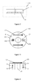
- FIG. 1 is a schematic drawing of a multi-turn absolute magnetic encoder of the present invention, containing a single turn counting unit 1 and a multi-turn counting unit 2, an input shaft 3, suitable for measuring the absolute position and number of turns for the rotating object under test.
- Single-turn counting unit 1 comprises a permanent magnet fixed to the counting wheel 4 (also called a permanent magnet counting wheel), a tunneling magnetoresistive angular displacement sensor 5, and a single-turn signal processing unit 6, the counting wheel 4 is mounted directly on the input shaft 3.
- the tunneling magnetoresistive angular displacement sensor 5 is used to measure the absolute position of the counting wheel 4 by detecting the angle of the rotating permanent magnet, and the measured result is the absolute position of the input shaft 3.
- Multi-turn counting unit 2 comprises M reduction gear stages 7 used to scale down the rotation speed of the input shaft, where M is an integer of 1. Each reduction gear stage has a corresponding input shaft 8, an output shaft 9, a permanent magnet coaxially fixed to the counting wheel 10, and a tunneling magnetoresistive angular displacement sensor 11. Multiturn counting unit 2 further includes a multi-turn signal processing unit 12 and multi-turn unit connected to each tunneling magnetoresistive angular displacement sensor in order to the sense and calculate the total number or rotations of shaft 3 tunneling magnetoresistive angular displacement sensor using the signals from the tunneling magnetoresistive angular displacement sensors.
- the reduction gear set of each stage 8 has a gear ratio of N: 1, which is transmitted to the output shaft 9, and repeated for M stages of the M+1 counting wheels, such that each successive counting wheel stage has it number of revolutions reduced by the ratio of N:1, where N is an integer greater than 1.
- N is an integer greater than 1.
- N 10
- Each level has a reduction gear set connecting its input shaft to the preceding level's output shaft.
- a permanent magnet is installed in the counting wheel 10 of each output shaft 9 such that it rotates with the output shaft.
- Tunneling magnetoresistive angular displacement sensor 11 measures the revolutions of the permanent magnet counting wheel 10 and the sensor signals are fed to the multi-turn signal processing unit 12.
- the multiturn signal processing unit to converts the measured sensor signal to the absolute rotational position of the corresponding counting wheel and thus the input shaft turns.
- the permanent magnet counting wheel 10 located on the output shaft cannot meet the requirement for counting more rotations, then more counting levels and associated reduction gear sets need to be added to fulfill the requirements.
- the approach is similar to carrying a digit in the next higher level, when the M counting wheel set rotates N turns, a digit must be added to the M+1 counting unit, when the M+1 counting unit rotates N turns, a digit must be added to the M+2 counting unit, and so on.
- the maximum number of turns that can be counted is therefore determined by the number of counting units, the transmission ratio N or base of the counting system N, where the reduction gear sets M represent the number of digits, where each M reduction gear set counts the number of rotations of the first M levels.
- FIG 2 is a schematic cross-sectional view of counting units 4 and 10.
- Counting units 4, 10 include a cylindrical ring permanent magnet 14 that is mounted on the non-magnetic counting wheel 13.
- the cylindrical ring permanent magnet 14 may have two permanent magnet subunits 100 and 300.
- Figures 3 and 4 below describe permanent magnet 100 and figures 5 and 6 below describe permanent magnet 300.
- FIGS 3 and 4 show schematic drawings of an embodiment of the permanent magnet 100 according to a preferred implementation of the present invention.
- the permanent magnet 100 has cylindrical ring geometry, and it is comprised of a permanent unit 101 and a permanent magnet unit 102, wherein permanent magnet unit 101 and permanent magnet unit 102 are symmetrically arranged about diametral cross-section 110.
- the magnetization directions 103 and 104 of permanent magnet units 101 and 102 are oriented in antiparallel directions along the axis.
- the magnetization 103 of the permanent magnet unit 101 and the magnetization 104 of permanent magnet unit 102 have the same magnitude.
- the permanent magnet 100 is a cylindrical ring with inner diameter 1-100mm, outer diameter of 3-200 mm, and has an axial length of 1-50 mm.
- the detection plane 120 or permanent magnet 100 is located adjacent and parallel to the end face or permanent magnet 100.
- the detection plane 120 is separated from the end surface of the cylindrical ring by a distance of 1-5 mm.
- the permanent magnet 100 produces a magnetic field component 121 in the detection plane 120.
- the portion of the detection plane 120 corresponding to the particular detector region 122 located within a certain radial distance from the axis, in particular the magnetic field components 121 within this detection area will have an angle that varies linearly with respect to the angle of the permanent magnet 100, which will be specifically described hereinafter.
- the composition of the permanent magnet material 100 is Alnico.
- the composition of the permanent magnet 100 is a ferrite ceramic material such as MO ⁇ 6Fe 2 O 3 , M is Ba, Sr or combinations of both.
- the permanent magnet material 100 composed of an alloy of NbFeB or FeCrCo.
- the permanent magnet 100 is composed of the permanent magnet powder embedded in plastic, rubber, or resin composite.
- FIGS. 5 and 6 show schematic drawings of another embodiment of the permanent magnet 300 of the present invention.
- the permanent magnet 300 has cylindrical ring geometry, and it is comprised of a permanent unit 301 and a permanent magnet unit 302, wherein permanent magnet unit 301 and permanent magnet unit 302 are symmetrically arranged about diametral cross-section 310.
- the magnetization directions 303 and 304 of permanent magnet units 301 and 302 are oriented along a diameter in the same direction.
- the magnetization 303 of the permanent magnet unit 301 and the magnetization 304 of permanent magnet unit 302 have the same magnitude.
- the permanent magnet 300 is a cylindrical ring with inner diameter 1-100mm, outer diameter of 3-200 mm, and has an axial length of 1-50 mm.
- the detection plane 320 is located in front of and parallel to the end face or permanent magnet 300. Preferably, the detection plane 320 is separated from the end surface of the cylindrical ring by a distance of 1-5 mm.
- the permanent magnet 300 produces a magnetic field component 321 along the detection plane 320.
- the detection plane 320 corresponding to the particular detector region 322 located within the cylindrical ring from the axial region specific radius, in particular the magnetic field components 321 within the detection area will have an angle that varies linearly with respect to the angle of the permanent magnet 300, which will be specifically described hereinafter.
- the composition of the permanent magnet material 300 is Alnico.
- the permanent magnet 300 is a ferrite ceramic material such as MO ⁇ 6Fe 2 O 3 , M is Ba, Sr or combinations of both.
- the permanent magnet material 100 composed of an alloy of NbFeB or FeCrCo.
- the permanent magnet 300 is composed of the permanent magnet powder embedded in plastic, rubber, or resin composite.
- Example 3 of the present invention shows the relative distance between the permanent magnets 100, 300 and he tunneling magnetoresistive angular displacement sensors 5, 11.
- Tunneling magnetoresistance sensors are located in the detection plane adjacent to the permanent magnet, for sensing the magnetic field from the permanent magnet and outputting a signal.
- the tunneling magnetoresistive sensors are disposed at a certain radial distance from the rotation axis within the detection plane of the permanent magnets, in this particular radial region of the detection plane of the rotating permanent magnet the magnetic field components have an angle ⁇ that varies linearly with the rotation angle ⁇ of said permanent magnet.
- Figures 7 and 8 are top and side views of the present invention, showing the detection plane of the permanent magnet 14 and the tunneling magnetoresistive angular displacement sensor 5, 11 , at a distance d from the end face 120, 320 of the permanent magnet.
- the permanent magnet detection plane origin is the center of of an XY coordinate system, as shown in Figure 7 .
- the cylindrical ring permanent magnet 14 has inner radius R i , outer radius R o , and thickness t;
- a tunneling magnetoresistive sensor 5, 11 detects the direction of the vector magnetic field at a point r(x, y), in the plane with respect to X-axis, and this direction is defined by angle ⁇ .
- the angle the tunneling magnetoresistive sensor 5, 11 remains fixed, while the permanent magnets 14 rotate about the axis of rotation, the axis is the origin of the measurement plane, r is the radius from the origin to the tunneling magnetoresistive angular displacement sensor 5, 11, the rotating magnet generates a rotating magnetic field the phase and amplitude of which are measured by a tunneling magnetoresistive angular displacement sensor 5, 11.
- the permanent magnet's angle is ⁇
- the angle of the rotating magnetic field is ⁇ .
- Figure 9 shows the magnetic field vector distribution in the detection plane 120 for permanent magnet 100.
- the two-dimensional magnetic field Bxy is calculated, here, r can be varied within the range (0, R o ) and the relationship between the phase angle ⁇ of the magnetic field and the phase angle relationship ⁇ of the rotating permanent magnet can be obtained; the relationship between the angles can be linear or non-linear.
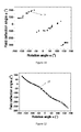
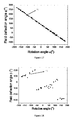
- Figure 10 shows the curve 23 of the rotating magnetic field of the permanent magnet and illustrates that the angle ⁇ of the magnetic field can be a linear function of ⁇
- Figure 11 shows the curve 24 for the rotating magnetic field of the permanent magnet illustrates a case where the angle ⁇ depends non-linearly and discontinuously on angle ⁇ . Also, as shown in FIG.
- the curve 25 representing the relationship between the permanent magnet angle ⁇ and the magnetic angle ⁇ may have varying degrees of nonlinearity with or without discontinuity.
- Figure 13 is a plot illustrating the dependence of the magnitude of Bxy as a function of rotation angle ⁇ , which is denoted as curve 26.
- the magnitude of the rotating magnetic field has W-shaped angular variation, with maximum and minimum values corresponding to BH and BL.
- a linear fit may be applied to the ⁇ and ⁇ curves shown in Figures 10 , 11, 12 in order to calculate the R 2 fitting parameter, where R 2 indicates stronger linear behavior as it approaches a value of 1.
- NORMALIZED_B indicate smaller magnetic field variation.
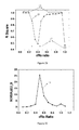
- Figure 14 shows linear fit parameter R 2 plotted as a function of r/R o .
- area 28 of the detection plane is a region that is well suited for the tunneling magnetoresistive sensor 5, 11, but region the region 29 is not well suited for the tunneling magnetoresistive sensor 5, 11.
- Figure 15 shows a curve NORMALIZED_B as a function of the relative position r/R o of the tunneling magnetoresistive angular displacement sensor 5, 11 within the detection plane. As can be seen from the curve 30 for a portion of region 28 the magnetic field variation for the tunneling magnetoresistive sensor 5, 11 is sufficiently small for good performance to be obtained.
- Figure 14 shows the magnetic field vector distribution in the detection plane 320 for permanent magnet 300.
- the two-dimensional magnetic field Bxy is calculated.
- angle ⁇ of the rotating magnetic field and angle ⁇ of the permanent magnet may have a linear relationship as in curve 31, a non-linear discontinuous relationship as shown in curve 32, and intermediate degrees of linearity as shown in curve 33.
- the behavior of curve 26 indicates a linear relationship between the rotating magnetic field angle ⁇ and angle ⁇ of the permanent magnets of the in the detection plane 320, such that the angle of the permanent magnets can be determined usefully for application as a magnetic encoder.
- Figure 20 shows the magnitude variation of the rotating magnetic field Bxy as a function of the permanent magnet rotation angle ⁇ . It can be seen from this curve 34, that the rotating magnetic field Bxy has an M-shaped periodic variation as a function of the permanent magnet's angle ⁇ .
- the ⁇ - ⁇ curve fitting parameters can be obtained at different relative positions r/R o , as shown in Figure 21 the R 2 fit parameter which indicates linearity, is plotted as curve 35, the portion 36 of the detection plane 22 is best suited for a tunneling magnetoresistive sensor 5,11, whereas region 37 is not well suited for a tunneling magnetoresistive sensor 5, 11. Further, it can be seen from Figure 22 , which shows NORMALIZED_B as a function of the relative position r/R o of the tunneling magnetoresistive sensor 5, 11 identified as curve 33 coincides with region 38 is small compared to region 37 which is the non-ideal operating area.
- permanent magnet 14 has a detection plane, in which there is a specific detection zone 28 and 36, suitable for using a tunneling magnetoresistive sensor to measure the angle ⁇ of the rotating magnetic field of a permanent magnet.
- a tunneling magnetoresistive sensor to measure the angle ⁇ of the rotating magnetic field of a permanent magnet.
- the rotation angle of the magnetic field measured by a tunneling magnetoresistive sensor can be converted into the rotation angle of the permanent magnet by the digital processing circuit in order to calculate and output a code representing the rotational angle of the permanent magnet, suitable for use in magnetic angle encoders.
- Tunneling magnetoresistive angular displacement sensor 5, 11 is formed from two orthogonal uniaxial full-bridge tunneling magnetoresistive angular displacement sensors, or two half bridges combined to form a full bridge, wherein the corresponding two half-bridge sensors have opposite sensing polarity.
- an external magnetic field is applied to a uniaxial tunneling magnetoresistive angular displacement sensor at angle of ⁇ to sensing axis, then it is also applied at an angle of ⁇ / 2- ⁇ to the sensing axis of the other uniaxial magnetoresistive angular displacement sensor.
- Figure 23 shows the output voltage signals of the two orthogonal uniaxial magnetoresistive angular displacement sensors 5, 11 as a function of rotation angle ⁇ for one full rotation of the counting wheel 4, 10.
- the output curves are sinusoidal with 90 degree phase separation, thus representing sine and cosine functions, such that the angle may be calculated from the arctangent of the signals.
Landscapes
- Physics & Mathematics (AREA)
- General Physics & Mathematics (AREA)
- Transmission And Conversion Of Sensor Element Output (AREA)
Applications Claiming Priority (2)
| Application Number | Priority Date | Filing Date | Title |
|---|---|---|---|
| CN201310011438.5A CN103925933B (zh) | 2013-01-11 | 2013-01-11 | 一种多圈绝对磁编码器 |
| PCT/CN2014/070472 WO2014108096A1 (fr) | 2013-01-11 | 2014-01-10 | Codeur électromagnétique absolu multitour |
Publications (3)
| Publication Number | Publication Date |
|---|---|
| EP2944924A1 true EP2944924A1 (fr) | 2015-11-18 |
| EP2944924A4 EP2944924A4 (fr) | 2016-08-17 |
| EP2944924B1 EP2944924B1 (fr) | 2020-10-21 |
Family
ID=51144234
Family Applications (1)
| Application Number | Title | Priority Date | Filing Date |
|---|---|---|---|
| EP14737770.9A Active EP2944924B1 (fr) | 2013-01-11 | 2014-01-10 | Codeur électromagnétique absolu multitour |
Country Status (5)
| Country | Link |
|---|---|
| US (1) | US9389099B2 (fr) |
| EP (1) | EP2944924B1 (fr) |
| JP (1) | JP6414936B2 (fr) |
| CN (1) | CN103925933B (fr) |
| WO (1) | WO2014108096A1 (fr) |
Cited By (1)
| Publication number | Priority date | Publication date | Assignee | Title |
|---|---|---|---|---|
| EP3686559A4 (fr) * | 2017-09-19 | 2021-06-02 | Minebea Mitsumi Inc. | Dispositif de détection d'angle, unité de spécification de quantité de rotation et unité de commande de rotation |
Families Citing this family (39)
| Publication number | Priority date | Publication date | Assignee | Title |
|---|---|---|---|---|
| CN103925933B (zh) | 2013-01-11 | 2016-12-28 | 江苏多维科技有限公司 | 一种多圈绝对磁编码器 |
| DE102013224247A1 (de) * | 2013-11-27 | 2015-05-28 | Dr. Johannes Heidenhain Gmbh | Multiturn-Drehgeber |
| CN104535092A (zh) * | 2014-12-28 | 2015-04-22 | 浙江风尚科技有限公司 | 伺服电机编码器及信号产生方法 |
| CN204421990U (zh) * | 2015-01-14 | 2015-06-24 | 江苏多维科技有限公司 | 一种可消除相邻转轮磁干涉的直读表 |
| CN104596605B (zh) * | 2015-02-04 | 2019-04-26 | 江苏多维科技有限公司 | 一种磁自动化流量记录器 |
| JP6561393B2 (ja) * | 2015-09-11 | 2019-08-21 | 下西技研工業株式会社 | 角度センサ、及び、角度センサによる角度検出方法 |
| JP2017058328A (ja) * | 2015-09-18 | 2017-03-23 | 日本電産サンキョー株式会社 | 直動回転検出器 |
| CN105490596B (zh) * | 2016-02-01 | 2017-12-08 | 重庆理工大学 | 一种永磁交流伺服电机的嵌入式位置检测系统 |
| JP6278050B2 (ja) | 2016-03-11 | 2018-02-14 | Tdk株式会社 | 回転角度検出装置及び回転機械装置 |
| JP2017178060A (ja) * | 2016-03-30 | 2017-10-05 | アルプス電気株式会社 | シフト装置 |
| CN106324534B (zh) * | 2016-09-13 | 2023-10-31 | 江苏多维科技有限公司 | 用于激光写入系统的磁电阻传感器晶元版图及激光扫描方法 |
| JP6545141B2 (ja) * | 2016-11-29 | 2019-07-17 | ミネベアミツミ株式会社 | アブソリュートエンコーダ |
| CN108953595A (zh) * | 2017-05-18 | 2018-12-07 | 泰科电子(上海)有限公司 | 用于感测档位转轴位置的传感系统 |
| CN107392302A (zh) * | 2017-06-30 | 2017-11-24 | 太仓宝达齿条有限公司 | 一种可以计数的齿轮 |
| CN107389102A (zh) * | 2017-06-30 | 2017-11-24 | 太仓宝达齿条有限公司 | 一种齿轮计数器 |
| CN107655399A (zh) * | 2017-07-12 | 2018-02-02 | 北京军立方机器人科技有限公司 | 一种多圈绝对值编码器及位置检测方法 |
| CN107504984A (zh) * | 2017-08-25 | 2017-12-22 | 上海岭先机器人科技股份有限公司 | 磁式编码器的磁环、磁环充磁与读取装置以及磁式编码器 |
| CN107941247A (zh) * | 2017-12-18 | 2018-04-20 | 嘉兴市锐鹰传感技术有限公司 | 一种被动唤醒式多圈编码器及工作方法 |
| DE102018117600A1 (de) * | 2018-07-20 | 2020-01-23 | Fraba B.V. | Drehwinkelmesssystem |
| US10914611B2 (en) * | 2018-08-27 | 2021-02-09 | Nxp B.V. | Magnetic field sensor system and method for rotation angle measurement |
| CN111130274B (zh) * | 2018-11-01 | 2021-09-17 | 台达电子工业股份有限公司 | 旋转检测装置及其适用的编码器与马达 |
| TWI724341B (zh) * | 2018-11-01 | 2021-04-11 | 台達電子工業股份有限公司 | 旋轉檢測裝置及其適用之編碼器與馬達 |
| US10921161B2 (en) * | 2018-12-04 | 2021-02-16 | China Automotive Systems, Inc. | Differential angle sensor |
| JP7193635B2 (ja) | 2018-12-06 | 2022-12-20 | 株式会社ハーモニック・ドライブ・システムズ | デュアルアブソリュートエンコーダ |
| CN109910061B (zh) * | 2019-03-13 | 2021-03-09 | 北京金钢科技有限公司 | 分离式磁双编码器 |
| JP7285691B2 (ja) * | 2019-05-16 | 2023-06-02 | ニデックインスツルメンツ株式会社 | 磁気センサ装置 |
| DE102019134392B4 (de) | 2019-12-13 | 2023-06-15 | Neura Robotics GmbH | Vorrichtung zur Bestimmung des Drehmoments und/oder des Drehwinkels zwischen einer ersten Welle und einer zweiten Welle |
| CN111649769A (zh) * | 2020-05-21 | 2020-09-11 | 江苏集萃智能制造技术研究所有限公司 | 一种机器人关节末端单圈磁编码器的多圈使用方法 |
| US11761793B2 (en) | 2020-05-26 | 2023-09-19 | Analog Devices International Unlimited Company | Magnetic sensor package |
| CN113050699B (zh) * | 2020-08-30 | 2024-01-12 | 惠州华阳通用电子有限公司 | 一种基于磁编码器的控制方法及装置 |
| CN115855124A (zh) * | 2021-09-23 | 2023-03-28 | 上海奥深精浦科技有限公司 | 多圈绝对值编码器 |
| CN114705420A (zh) * | 2022-03-30 | 2022-07-05 | 江苏眸视机器人科技有限公司 | 一种辊棒转动检测的装置、方法、系统、设备及介质 |
| CN114739465B (zh) * | 2022-03-31 | 2024-12-20 | 广州市自来水有限公司 | 一种智能水表机电转换方法 |
| CN116222625B (zh) * | 2023-02-09 | 2023-09-12 | 哈尔滨理工大学 | 一种多并列无磁钢的多圈编码器装置及其计数方法 |
| CN116222624B (zh) * | 2023-02-09 | 2023-09-26 | 哈尔滨理工大学 | 一种电磁齿轮多圈式磁电编码器及其计圈数方法 |
| CN116465299A (zh) * | 2023-04-13 | 2023-07-21 | 无锡市航鹄科技有限公司 | 一种用于高速旋转的绝对式传感器及其绝对位置检测方法 |
| JPWO2024252459A1 (fr) * | 2023-06-05 | 2024-12-12 | ||
| CN116817740B (zh) * | 2023-08-29 | 2023-12-01 | 西安交通大学 | 一种基于离轴磁场传感器阵列的表盘读数感应装置及方法 |
| CN117387664B (zh) * | 2023-10-10 | 2024-09-03 | 山西省机电设计研究院有限公司 | 工业级伺服系统 |
Family Cites Families (32)
| Publication number | Priority date | Publication date | Assignee | Title |
|---|---|---|---|---|
| US5789917A (en) * | 1990-12-05 | 1998-08-04 | Moving Magnet Technologie Sa | Magnetic position sensor with hall probe formed in an air gap of a stator |
| DE19820014A1 (de) * | 1998-05-06 | 1999-11-11 | Heidenhain Gmbh Dr Johannes | Multiturn-Codedrehgeber |
| DE10041092A1 (de) * | 2000-08-22 | 2002-03-07 | Bosch Gmbh Robert | Verfahren zur Korrektur eines Phasenwinkels bei der Abtastung einer Codespur |
| JP3775257B2 (ja) * | 2001-07-30 | 2006-05-17 | アイシン精機株式会社 | 角度センサ |
| CN1267707C (zh) * | 2001-10-19 | 2006-08-02 | 株式会社安川电机 | 多转型编码器 |
| JP4132835B2 (ja) * | 2002-01-23 | 2008-08-13 | 株式会社デンソー | 回転数検出装置 |
| ATE402396T1 (de) * | 2002-10-10 | 2008-08-15 | Ebm Papst St Georgen Gmbh & Co | Vorrichtung zum erfassen des absolutwinkels einer welle |
| JP4079043B2 (ja) * | 2003-06-13 | 2008-04-23 | 株式会社デンソー | 回転角度検出装置 |
| US7023202B2 (en) * | 2003-08-01 | 2006-04-04 | Japan Servo Co., Ltd. | Magnetic rotary position sensor |
| CN1997876A (zh) * | 2004-06-16 | 2007-07-11 | 株式会社安川电机 | 磁性编码装置 |
| JP4543932B2 (ja) * | 2005-01-12 | 2010-09-15 | 株式会社デンソー | 回転角度検出装置 |
| JP3848670B1 (ja) * | 2005-07-20 | 2006-11-22 | 株式会社トーメンエレクトロニクス | 回転角度検出装置 |
| JP2007113932A (ja) * | 2005-10-18 | 2007-05-10 | Harmonic Drive Syst Ind Co Ltd | ギヤ付きモータの多回転絶対値エンコーダ |
| DE102006018627A1 (de) * | 2006-04-21 | 2007-10-25 | Siemens Ag | Magnetischer Drehwinkelgeber |
| CN201016743Y (zh) * | 2007-03-02 | 2008-02-06 | 周益祺 | 多圈绝对量磁电开关型编码器 |
| DE112008003576T5 (de) * | 2008-01-04 | 2011-01-20 | Allegro Microsystems, Inc., Worcester | Verfahren und Vorrichtung für einen Winkelsensor |
| DE102008051083A1 (de) * | 2008-10-09 | 2010-04-15 | Dr. Johannes Heidenhain Gmbh | Multiturn-Drehgeber |
| JP5263024B2 (ja) * | 2009-06-18 | 2013-08-14 | 株式会社日立製作所 | 回転角検出装置および回転速度検出装置 |
| DE102009029431A1 (de) * | 2009-09-14 | 2011-03-24 | Dr. Johannes Heidenhain Gmbh | Multiturn-Drehgeber |
| JP5287635B2 (ja) | 2009-09-24 | 2013-09-11 | 株式会社ジェイテクト | 回転角センサ、モータ、回転角検出装置、及び電動パワーステアリング装置 |
| JP5079846B2 (ja) * | 2010-06-03 | 2012-11-21 | 東京コスモス電機株式会社 | 位置検出装置 |
| JP5391157B2 (ja) * | 2010-06-23 | 2014-01-15 | オークマ株式会社 | 回転角度検出装置 |
| DE102011078281A1 (de) * | 2010-08-04 | 2012-02-09 | Continental Teves Ag & Co. Ohg | Sensoranordnung mit magnetischem Index-Encoder in einer Lagerdichtung |
| CN201748928U (zh) * | 2010-09-07 | 2011-02-16 | 王建国 | 隧道磁电阻效应磁性编码器 |
| US9062990B2 (en) * | 2011-02-25 | 2015-06-23 | Allegro Microsystems, Llc | Circular vertical hall magnetic field sensing element and method with a plurality of continuous output signals |
| CN202119391U (zh) | 2011-03-03 | 2012-01-18 | 江苏多维科技有限公司 | 一种独立封装的磁电阻角度传感器 |
| CN202126270U (zh) * | 2011-05-30 | 2012-01-25 | 扬州电力设备修造厂 | 非接触式无源保持光磁多回转绝对位置传感器 |
| DE102011118928B4 (de) * | 2011-11-21 | 2017-12-07 | Bourns, Inc. | Drehwinkelsensor |
| CN203300354U (zh) * | 2013-01-05 | 2013-11-20 | 江苏多维科技有限公司 | 一种适用于角度磁编码器的永磁体 |
| CN203116756U (zh) * | 2013-01-09 | 2013-08-07 | 江苏多维科技有限公司 | 一种角度磁编码器和电子水表 |
| CN103925933B (zh) | 2013-01-11 | 2016-12-28 | 江苏多维科技有限公司 | 一种多圈绝对磁编码器 |
| CN203203607U (zh) * | 2013-01-11 | 2013-09-18 | 江苏多维科技有限公司 | 一种多圈绝对磁编码器 |
-
2013
- 2013-01-11 CN CN201310011438.5A patent/CN103925933B/zh active Active
-
2014
- 2014-01-10 JP JP2015551977A patent/JP6414936B2/ja active Active
- 2014-01-10 WO PCT/CN2014/070472 patent/WO2014108096A1/fr not_active Ceased
- 2014-01-10 US US14/760,355 patent/US9389099B2/en active Active
- 2014-01-10 EP EP14737770.9A patent/EP2944924B1/fr active Active
Cited By (2)
| Publication number | Priority date | Publication date | Assignee | Title |
|---|---|---|---|---|
| EP3686559A4 (fr) * | 2017-09-19 | 2021-06-02 | Minebea Mitsumi Inc. | Dispositif de détection d'angle, unité de spécification de quantité de rotation et unité de commande de rotation |
| US11404938B2 (en) | 2017-09-19 | 2022-08-02 | Minebea Mitsumi Inc. | Angle detection apparatus, rotation amount specification unit, and rotary driving unit |
Also Published As
| Publication number | Publication date |
|---|---|
| JP2016503174A (ja) | 2016-02-01 |
| WO2014108096A1 (fr) | 2014-07-17 |
| CN103925933A (zh) | 2014-07-16 |
| US9389099B2 (en) | 2016-07-12 |
| CN103925933B (zh) | 2016-12-28 |
| US20150369636A1 (en) | 2015-12-24 |
| EP2944924A4 (fr) | 2016-08-17 |
| JP6414936B2 (ja) | 2018-10-31 |
| EP2944924B1 (fr) | 2020-10-21 |
Similar Documents
| Publication | Publication Date | Title |
|---|---|---|
| EP2944924B1 (fr) | Codeur électromagnétique absolu multitour | |
| JP6412014B2 (ja) | 磁気角エンコーダおよび電子水道メータ | |
| EP2942794B1 (fr) | Aimant permanent destiné à un codeur d'angle magnétique | |
| JP5079816B2 (ja) | 好ましくは擬似正弦的に変化する磁石外形を有する磁気式位置センサ | |
| US8659289B2 (en) | Rotating field sensor | |
| US9719771B2 (en) | Rotation angle sensor for absolute rotation angle determination even upon multiple revolutions | |
| US8970210B2 (en) | Bidirectional magnetic position sensor having field rotation | |
| EP3184954A1 (fr) | Capteur d'angle magnéto-résistif d'axe z double | |
| US20110254543A1 (en) | Magnetic position sensor with field direction measurement and flux collector | |
| CN203203607U (zh) | 一种多圈绝对磁编码器 | |
| CN103154672A (zh) | 多圈磁性绝对位置检测装置 | |
| JP6420763B2 (ja) | 直読式計量装置および直読式水量計 | |
| US20210255003A1 (en) | A magnetic encoder | |
| US9400166B2 (en) | Sensor arrangement | |
| EP3423791B1 (fr) | Ensemble utilisant un capteur de champ magnétique pour la détection d'une rotation et d'un déplacement linéaire d'un objet | |
| US9587963B2 (en) | Brushless linear rotary transformer | |
| Wang et al. | An angle displacement sensor using a simple gear | |
| CN203116756U (zh) | 一种角度磁编码器和电子水表 | |
| CN203300354U (zh) | 一种适用于角度磁编码器的永磁体 | |
| CN116793400A (zh) | 一种高精度的单编码盘绝对式磁编码器测量系统 | |
| CN111693910B (zh) | 用于确定旋转构件的至少一个旋转参数的系统 |
Legal Events
| Date | Code | Title | Description |
|---|---|---|---|
| PUAI | Public reference made under article 153(3) epc to a published international application that has entered the european phase |
Free format text: ORIGINAL CODE: 0009012 |
|
| 17P | Request for examination filed |
Effective date: 20150708 |
|
| AK | Designated contracting states |
Kind code of ref document: A1 Designated state(s): AL AT BE BG CH CY CZ DE DK EE ES FI FR GB GR HR HU IE IS IT LI LT LU LV MC MK MT NL NO PL PT RO RS SE SI SK SM TR |
|
| AX | Request for extension of the european patent |
Extension state: BA ME |
|
| DAX | Request for extension of the european patent (deleted) | ||
| REG | Reference to a national code |
Ref country code: DE Ref legal event code: R079 Ref document number: 602014071450 Country of ref document: DE Free format text: PREVIOUS MAIN CLASS: G01D0005120000 Ipc: G01D0005140000 |
|
| A4 | Supplementary search report drawn up and despatched |
Effective date: 20160720 |
|
| RIC1 | Information provided on ipc code assigned before grant |
Ipc: G01D 5/14 20060101AFI20160714BHEP Ipc: G01D 5/249 20060101ALI20160714BHEP |
|
| STAA | Information on the status of an ep patent application or granted ep patent |
Free format text: STATUS: EXAMINATION IS IN PROGRESS |
|
| 17Q | First examination report despatched |
Effective date: 20180522 |
|
| GRAP | Despatch of communication of intention to grant a patent |
Free format text: ORIGINAL CODE: EPIDOSNIGR1 |
|
| STAA | Information on the status of an ep patent application or granted ep patent |
Free format text: STATUS: GRANT OF PATENT IS INTENDED |
|
| INTG | Intention to grant announced |
Effective date: 20200420 |
|
| GRAJ | Information related to disapproval of communication of intention to grant by the applicant or resumption of examination proceedings by the epo deleted |
Free format text: ORIGINAL CODE: EPIDOSDIGR1 |
|
| STAA | Information on the status of an ep patent application or granted ep patent |
Free format text: STATUS: EXAMINATION IS IN PROGRESS |
|
| GRAR | Information related to intention to grant a patent recorded |
Free format text: ORIGINAL CODE: EPIDOSNIGR71 |
|
| GRAS | Grant fee paid |
Free format text: ORIGINAL CODE: EPIDOSNIGR3 |
|
| STAA | Information on the status of an ep patent application or granted ep patent |
Free format text: STATUS: GRANT OF PATENT IS INTENDED |
|
| GRAA | (expected) grant |
Free format text: ORIGINAL CODE: 0009210 |
|
| STAA | Information on the status of an ep patent application or granted ep patent |
Free format text: STATUS: THE PATENT HAS BEEN GRANTED |
|
| INTC | Intention to grant announced (deleted) | ||
| INTG | Intention to grant announced |
Effective date: 20200910 |
|
| AK | Designated contracting states |
Kind code of ref document: B1 Designated state(s): AL AT BE BG CH CY CZ DE DK EE ES FI FR GB GR HR HU IE IS IT LI LT LU LV MC MK MT NL NO PL PT RO RS SE SI SK SM TR |
|
| REG | Reference to a national code |
Ref country code: GB Ref legal event code: FG4D |
|
| REG | Reference to a national code |
Ref country code: CH Ref legal event code: EP |
|
| REG | Reference to a national code |
Ref country code: IE Ref legal event code: FG4D |
|
| REG | Reference to a national code |
Ref country code: DE Ref legal event code: R096 Ref document number: 602014071450 Country of ref document: DE |
|
| REG | Reference to a national code |
Ref country code: AT Ref legal event code: REF Ref document number: 1326269 Country of ref document: AT Kind code of ref document: T Effective date: 20201115 |
|
| REG | Reference to a national code |
Ref country code: AT Ref legal event code: MK05 Ref document number: 1326269 Country of ref document: AT Kind code of ref document: T Effective date: 20201021 |
|
| REG | Reference to a national code |
Ref country code: NL Ref legal event code: MP Effective date: 20201021 |
|
| PG25 | Lapsed in a contracting state [announced via postgrant information from national office to epo] |
Ref country code: GR Free format text: LAPSE BECAUSE OF FAILURE TO SUBMIT A TRANSLATION OF THE DESCRIPTION OR TO PAY THE FEE WITHIN THE PRESCRIBED TIME-LIMIT Effective date: 20210122 Ref country code: FI Free format text: LAPSE BECAUSE OF FAILURE TO SUBMIT A TRANSLATION OF THE DESCRIPTION OR TO PAY THE FEE WITHIN THE PRESCRIBED TIME-LIMIT Effective date: 20201021 Ref country code: RS Free format text: LAPSE BECAUSE OF FAILURE TO SUBMIT A TRANSLATION OF THE DESCRIPTION OR TO PAY THE FEE WITHIN THE PRESCRIBED TIME-LIMIT Effective date: 20201021 Ref country code: NL Free format text: LAPSE BECAUSE OF FAILURE TO SUBMIT A TRANSLATION OF THE DESCRIPTION OR TO PAY THE FEE WITHIN THE PRESCRIBED TIME-LIMIT Effective date: 20201021 Ref country code: NO Free format text: LAPSE BECAUSE OF FAILURE TO SUBMIT A TRANSLATION OF THE DESCRIPTION OR TO PAY THE FEE WITHIN THE PRESCRIBED TIME-LIMIT Effective date: 20210121 Ref country code: PT Free format text: LAPSE BECAUSE OF FAILURE TO SUBMIT A TRANSLATION OF THE DESCRIPTION OR TO PAY THE FEE WITHIN THE PRESCRIBED TIME-LIMIT Effective date: 20210222 |
|
| REG | Reference to a national code |
Ref country code: LT Ref legal event code: MG4D |
|
| PG25 | Lapsed in a contracting state [announced via postgrant information from national office to epo] |
Ref country code: AT Free format text: LAPSE BECAUSE OF FAILURE TO SUBMIT A TRANSLATION OF THE DESCRIPTION OR TO PAY THE FEE WITHIN THE PRESCRIBED TIME-LIMIT Effective date: 20201021 Ref country code: ES Free format text: LAPSE BECAUSE OF FAILURE TO SUBMIT A TRANSLATION OF THE DESCRIPTION OR TO PAY THE FEE WITHIN THE PRESCRIBED TIME-LIMIT Effective date: 20201021 Ref country code: BG Free format text: LAPSE BECAUSE OF FAILURE TO SUBMIT A TRANSLATION OF THE DESCRIPTION OR TO PAY THE FEE WITHIN THE PRESCRIBED TIME-LIMIT Effective date: 20210121 Ref country code: SE Free format text: LAPSE BECAUSE OF FAILURE TO SUBMIT A TRANSLATION OF THE DESCRIPTION OR TO PAY THE FEE WITHIN THE PRESCRIBED TIME-LIMIT Effective date: 20201021 Ref country code: IS Free format text: LAPSE BECAUSE OF FAILURE TO SUBMIT A TRANSLATION OF THE DESCRIPTION OR TO PAY THE FEE WITHIN THE PRESCRIBED TIME-LIMIT Effective date: 20210221 Ref country code: LV Free format text: LAPSE BECAUSE OF FAILURE TO SUBMIT A TRANSLATION OF THE DESCRIPTION OR TO PAY THE FEE WITHIN THE PRESCRIBED TIME-LIMIT Effective date: 20201021 Ref country code: PL Free format text: LAPSE BECAUSE OF FAILURE TO SUBMIT A TRANSLATION OF THE DESCRIPTION OR TO PAY THE FEE WITHIN THE PRESCRIBED TIME-LIMIT Effective date: 20201021 |
|
| PG25 | Lapsed in a contracting state [announced via postgrant information from national office to epo] |
Ref country code: HR Free format text: LAPSE BECAUSE OF FAILURE TO SUBMIT A TRANSLATION OF THE DESCRIPTION OR TO PAY THE FEE WITHIN THE PRESCRIBED TIME-LIMIT Effective date: 20201021 |
|
| REG | Reference to a national code |
Ref country code: DE Ref legal event code: R097 Ref document number: 602014071450 Country of ref document: DE |
|
| PG25 | Lapsed in a contracting state [announced via postgrant information from national office to epo] |
Ref country code: SK Free format text: LAPSE BECAUSE OF FAILURE TO SUBMIT A TRANSLATION OF THE DESCRIPTION OR TO PAY THE FEE WITHIN THE PRESCRIBED TIME-LIMIT Effective date: 20201021 Ref country code: RO Free format text: LAPSE BECAUSE OF FAILURE TO SUBMIT A TRANSLATION OF THE DESCRIPTION OR TO PAY THE FEE WITHIN THE PRESCRIBED TIME-LIMIT Effective date: 20201021 Ref country code: LT Free format text: LAPSE BECAUSE OF FAILURE TO SUBMIT A TRANSLATION OF THE DESCRIPTION OR TO PAY THE FEE WITHIN THE PRESCRIBED TIME-LIMIT Effective date: 20201021 Ref country code: EE Free format text: LAPSE BECAUSE OF FAILURE TO SUBMIT A TRANSLATION OF THE DESCRIPTION OR TO PAY THE FEE WITHIN THE PRESCRIBED TIME-LIMIT Effective date: 20201021 Ref country code: CZ Free format text: LAPSE BECAUSE OF FAILURE TO SUBMIT A TRANSLATION OF THE DESCRIPTION OR TO PAY THE FEE WITHIN THE PRESCRIBED TIME-LIMIT Effective date: 20201021 Ref country code: SM Free format text: LAPSE BECAUSE OF FAILURE TO SUBMIT A TRANSLATION OF THE DESCRIPTION OR TO PAY THE FEE WITHIN THE PRESCRIBED TIME-LIMIT Effective date: 20201021 |
|
| PLBE | No opposition filed within time limit |
Free format text: ORIGINAL CODE: 0009261 |
|
| STAA | Information on the status of an ep patent application or granted ep patent |
Free format text: STATUS: NO OPPOSITION FILED WITHIN TIME LIMIT |
|
| PG25 | Lapsed in a contracting state [announced via postgrant information from national office to epo] |
Ref country code: DK Free format text: LAPSE BECAUSE OF FAILURE TO SUBMIT A TRANSLATION OF THE DESCRIPTION OR TO PAY THE FEE WITHIN THE PRESCRIBED TIME-LIMIT Effective date: 20201021 Ref country code: MC Free format text: LAPSE BECAUSE OF FAILURE TO SUBMIT A TRANSLATION OF THE DESCRIPTION OR TO PAY THE FEE WITHIN THE PRESCRIBED TIME-LIMIT Effective date: 20201021 |
|
| REG | Reference to a national code |
Ref country code: CH Ref legal event code: PL |
|
| 26N | No opposition filed |
Effective date: 20210722 |
|
| PG25 | Lapsed in a contracting state [announced via postgrant information from national office to epo] |
Ref country code: LU Free format text: LAPSE BECAUSE OF NON-PAYMENT OF DUE FEES Effective date: 20210110 |
|
| REG | Reference to a national code |
Ref country code: BE Ref legal event code: MM Effective date: 20210131 |
|
| PG25 | Lapsed in a contracting state [announced via postgrant information from national office to epo] |
Ref country code: AL Free format text: LAPSE BECAUSE OF FAILURE TO SUBMIT A TRANSLATION OF THE DESCRIPTION OR TO PAY THE FEE WITHIN THE PRESCRIBED TIME-LIMIT Effective date: 20201021 Ref country code: IT Free format text: LAPSE BECAUSE OF FAILURE TO SUBMIT A TRANSLATION OF THE DESCRIPTION OR TO PAY THE FEE WITHIN THE PRESCRIBED TIME-LIMIT Effective date: 20201021 |
|
| PG25 | Lapsed in a contracting state [announced via postgrant information from national office to epo] |
Ref country code: CH Free format text: LAPSE BECAUSE OF NON-PAYMENT OF DUE FEES Effective date: 20210131 Ref country code: SI Free format text: LAPSE BECAUSE OF FAILURE TO SUBMIT A TRANSLATION OF THE DESCRIPTION OR TO PAY THE FEE WITHIN THE PRESCRIBED TIME-LIMIT Effective date: 20201021 Ref country code: LI Free format text: LAPSE BECAUSE OF NON-PAYMENT OF DUE FEES Effective date: 20210131 |
|
| PG25 | Lapsed in a contracting state [announced via postgrant information from national office to epo] |
Ref country code: IE Free format text: LAPSE BECAUSE OF NON-PAYMENT OF DUE FEES Effective date: 20210110 |
|
| PG25 | Lapsed in a contracting state [announced via postgrant information from national office to epo] |
Ref country code: IS Free format text: LAPSE BECAUSE OF FAILURE TO SUBMIT A TRANSLATION OF THE DESCRIPTION OR TO PAY THE FEE WITHIN THE PRESCRIBED TIME-LIMIT Effective date: 20210221 |
|
| PG25 | Lapsed in a contracting state [announced via postgrant information from national office to epo] |
Ref country code: BE Free format text: LAPSE BECAUSE OF NON-PAYMENT OF DUE FEES Effective date: 20210131 |
|
| REG | Reference to a national code |
Ref country code: DE Ref legal event code: R083 Ref document number: 602014071450 Country of ref document: DE |
|
| PG25 | Lapsed in a contracting state [announced via postgrant information from national office to epo] |
Ref country code: HU Free format text: LAPSE BECAUSE OF FAILURE TO SUBMIT A TRANSLATION OF THE DESCRIPTION OR TO PAY THE FEE WITHIN THE PRESCRIBED TIME-LIMIT; INVALID AB INITIO Effective date: 20140110 |
|
| PG25 | Lapsed in a contracting state [announced via postgrant information from national office to epo] |
Ref country code: CY Free format text: LAPSE BECAUSE OF FAILURE TO SUBMIT A TRANSLATION OF THE DESCRIPTION OR TO PAY THE FEE WITHIN THE PRESCRIBED TIME-LIMIT Effective date: 20201021 |
|
| P01 | Opt-out of the competence of the unified patent court (upc) registered |
Effective date: 20230626 |
|
| PG25 | Lapsed in a contracting state [announced via postgrant information from national office to epo] |
Ref country code: MK Free format text: LAPSE BECAUSE OF FAILURE TO SUBMIT A TRANSLATION OF THE DESCRIPTION OR TO PAY THE FEE WITHIN THE PRESCRIBED TIME-LIMIT Effective date: 20201021 |
|
| PG25 | Lapsed in a contracting state [announced via postgrant information from national office to epo] |
Ref country code: TR Free format text: LAPSE BECAUSE OF FAILURE TO SUBMIT A TRANSLATION OF THE DESCRIPTION OR TO PAY THE FEE WITHIN THE PRESCRIBED TIME-LIMIT Effective date: 20201021 |
|
| PG25 | Lapsed in a contracting state [announced via postgrant information from national office to epo] |
Ref country code: MT Free format text: LAPSE BECAUSE OF FAILURE TO SUBMIT A TRANSLATION OF THE DESCRIPTION OR TO PAY THE FEE WITHIN THE PRESCRIBED TIME-LIMIT Effective date: 20201021 |
|
| PGFP | Annual fee paid to national office [announced via postgrant information from national office to epo] |
Ref country code: GB Payment date: 20260127 Year of fee payment: 13 |
|
| PGFP | Annual fee paid to national office [announced via postgrant information from national office to epo] |
Ref country code: DE Payment date: 20260128 Year of fee payment: 13 |
|
| PGFP | Annual fee paid to national office [announced via postgrant information from national office to epo] |
Ref country code: FR Payment date: 20260126 Year of fee payment: 13 |