EP2944937B1 - Bidirektionale elektrische miniatur-hochdruckgaspumpe - Google Patents
Bidirektionale elektrische miniatur-hochdruckgaspumpe Download PDFInfo
- Publication number
- EP2944937B1 EP2944937B1 EP15175217.7A EP15175217A EP2944937B1 EP 2944937 B1 EP2944937 B1 EP 2944937B1 EP 15175217 A EP15175217 A EP 15175217A EP 2944937 B1 EP2944937 B1 EP 2944937B1
- Authority
- EP
- European Patent Office
- Prior art keywords
- pressure
- cylinder
- high pressure
- gas
- way valve
- Prior art date
- Legal status (The legal status is an assumption and is not a legal conclusion. Google has not performed a legal analysis and makes no representation as to the accuracy of the status listed.)
- Active
Links
Images


Classifications
-
- F—MECHANICAL ENGINEERING; LIGHTING; HEATING; WEAPONS; BLASTING
- F04—POSITIVE - DISPLACEMENT MACHINES FOR LIQUIDS; PUMPS FOR LIQUIDS OR ELASTIC FLUIDS
- F04B—POSITIVE-DISPLACEMENT MACHINES FOR LIQUIDS; PUMPS
- F04B35/00—Piston pumps specially adapted for elastic fluids and characterised by the driving means to their working members, or by combination with, or adaptation to, specific driving engines or motors, not otherwise provided for
- F04B35/04—Piston pumps specially adapted for elastic fluids and characterised by the driving means to their working members, or by combination with, or adaptation to, specific driving engines or motors, not otherwise provided for the means being electric
-
- F—MECHANICAL ENGINEERING; LIGHTING; HEATING; WEAPONS; BLASTING
- F04—POSITIVE - DISPLACEMENT MACHINES FOR LIQUIDS; PUMPS FOR LIQUIDS OR ELASTIC FLUIDS
- F04B—POSITIVE-DISPLACEMENT MACHINES FOR LIQUIDS; PUMPS
- F04B19/00—Machines or pumps having pertinent characteristics not provided for in, or of interest apart from, groups F04B1/00 - F04B17/00
- F04B19/006—Micropumps
-
- F—MECHANICAL ENGINEERING; LIGHTING; HEATING; WEAPONS; BLASTING
- F04—POSITIVE - DISPLACEMENT MACHINES FOR LIQUIDS; PUMPS FOR LIQUIDS OR ELASTIC FLUIDS
- F04B—POSITIVE-DISPLACEMENT MACHINES FOR LIQUIDS; PUMPS
- F04B39/00—Component parts, details, or accessories, of pumps or pumping systems specially adapted for elastic fluids, not otherwise provided for in, or of interest apart from, groups F04B25/00 - F04B37/00
- F04B39/0005—Component parts, details, or accessories, of pumps or pumping systems specially adapted for elastic fluids, not otherwise provided for in, or of interest apart from, groups F04B25/00 - F04B37/00 adaptations of pistons
-
- F—MECHANICAL ENGINEERING; LIGHTING; HEATING; WEAPONS; BLASTING
- F04—POSITIVE - DISPLACEMENT MACHINES FOR LIQUIDS; PUMPS FOR LIQUIDS OR ELASTIC FLUIDS
- F04B—POSITIVE-DISPLACEMENT MACHINES FOR LIQUIDS; PUMPS
- F04B39/00—Component parts, details, or accessories, of pumps or pumping systems specially adapted for elastic fluids, not otherwise provided for in, or of interest apart from, groups F04B25/00 - F04B37/00
- F04B39/0094—Component parts, details, or accessories, of pumps or pumping systems specially adapted for elastic fluids, not otherwise provided for in, or of interest apart from, groups F04B25/00 - F04B37/00 crankshaft
-
- F—MECHANICAL ENGINEERING; LIGHTING; HEATING; WEAPONS; BLASTING
- F04—POSITIVE - DISPLACEMENT MACHINES FOR LIQUIDS; PUMPS FOR LIQUIDS OR ELASTIC FLUIDS
- F04B—POSITIVE-DISPLACEMENT MACHINES FOR LIQUIDS; PUMPS
- F04B51/00—Testing machines, pumps, or pumping installations
-
- G—PHYSICS
- G01—MEASURING; TESTING
- G01L—MEASURING FORCE, STRESS, TORQUE, WORK, MECHANICAL POWER, MECHANICAL EFFICIENCY, OR FLUID PRESSURE
- G01L27/00—Testing or calibrating of apparatus for measuring fluid pressure
- G01L27/002—Calibrating, i.e. establishing true relation between transducer output value and value to be measured, zeroing, linearising or span error determination
- G01L27/005—Apparatus for calibrating pressure sensors
-
- G—PHYSICS
- G05—CONTROLLING; REGULATING
- G05D—SYSTEMS FOR CONTROLLING OR REGULATING NON-ELECTRIC VARIABLES
- G05D16/00—Control of fluid pressure
- G05D16/20—Control of fluid pressure characterised by the use of electric means
- G05D16/2006—Control of fluid pressure characterised by the use of electric means with direct action of electric energy on controlling means
- G05D16/208—Control of fluid pressure characterised by the use of electric means with direct action of electric energy on controlling means using a combination of controlling means as defined in G05D16/2013 and G05D16/2066
Definitions
- the present invention pertains to the area of measurement and calibration of pressure instrumentation, and mainly relates to automated calibration in that area. More particularly, it relates to an automated calibration equipment that is convenient to be carried to field, performs both calibration of pressure and output electric signals on pressure instruments, and can switch standard ranges.
- US 2009/0068040 A1 discloses a gas pump according to the preamble of claim 1.
- the pressure controller and an externally connected gas cylinder together form a device system.
- the gas cylinder provides a gas pressure according to a set pressure, and through automatic monitoring of a pressure sensor and automatic control of a pressure regulator, a set pressure output is provided for access of pressure instruments to be calibrated, so as to perform automatic calibration on the pressure instruments.
- This method overcomes the disadvantages of human observation and manually operated pressure regulation, can automatically monitor and adjust the pressure, and significantly improves the working efficiency.
- the conventional pressure controller is not portable due to its own large volume, the use of AC power supply for supplying power, large volume of the external gas cylinder, and place restriction on chemical gases within the cylinder, etc.
- the disadvantage that calibration can not be implemented on-site.
- prior art pressure controllers typically one pressure sensor is used as a standard device and is incorporated in the instrument.
- prior art pressure controllers there are also cases of using two pressure sensors, where one is used as a pressure standard device, and the other is used to measure atmospheric pressure.
- the measuring range is a fixed single range, limiting pressure measurement and control range of the instrument.
- measurement accuracy will be affected by the measuring ranges. This requires a plurality of multi-range pressure controller devices at the time of pressure instrument calibration, causing inconvenience to on-site detection.
- the object of the present invention is to provide a high pressure bidirectional miniatur electric gas pump that is convenient to carry, and is suitable for use in the industrial field, namely, for a multi-range on-site full-automatic pressure and electric signal calibration instrument.
- This object is solved by a pump as defined in claim 1.
- the gas pressurizing pump comprises a motor, an eccentric shaft, a swing rod, a pump body, a left cylinder body and a right cylinder body, a piston rod, and an one-way valve body and a cylinder head attached to each of the cylinder bodies, wherein the pump body is a connecting member, the motor is fixed to the pump body, and a motor shaft extends into the pump body and is connected with the eccentric shaft; the eccentric shaft is of a cylindrical shape, and has a driving pin deviated from the axis at one end thereof, with the driving pin extending through a mounting hole in the flat-shaped swing rod; the swing rod is connected to the horizontally disposed piston rod through a screw; the piston rod is of a cylindrical shape, opposite ends thereof being mounted with sealing rings and extending into the left and right cylinder bodies, respectively; the cylinder body is of a cylindrical structure, and the two cylinder bodies are mounted at opposite ends of the pump body, respectively; the two cylinder bodies are sequentially provided at outer ends thereof with the one-way valve bodies and the
- the piston rod forms sealing, through the sealing rings mounted at the opposite ends thereof, at an inner wall of the cylinder bodies; and a swing motion of the swing rod drives the piston rod to reciprocate within the two cylinder bodies along the axis.
- each of the cylinder bodies is mounted with two reversely disposed one-way valve bodies, wherein one of the one-way valve bodies is communicated with the external air, and the other of the one-way valve bodies is communicated with the compressed air line.
- the one-way valve body is formed through assembly of a cavity seal body, an elastic arm, a metal pad, and a sealing ring, wherein the elastic arm extends inwardly from the cavity seal body and is coupled with a top end of the metal pad, and a bottom end of the metal pad fixes the sealing ring.
- the power supply unit is a self-powered system by battery, or an external power source.
- the pressure control unit comprises a pressure controller and a single-chip microcomputer system, wherein a gas path portion of the pressure controller includes an intake valve, a buffer, a micro-pressure adjusting mechanism, an exhaust valve, and a standard pressure output port; the standard pressure output port is provided with two pressure connectors connected in parallel; the intake valve is communicated with a high pressure gas output pipe of the gas pressurizing pump; the buffer is a pressure accommodating chamber used to stabilize and preserve gas pressure output by the intake valve, an outlet port of the buffer is communicated with a cylinder in the micro-pressure adjusting mechanism, and a plunger in the cylinder is connected with a screw mechanism; the exhaust valve is installed in a pressure output pipe and is communicated with the atmosphere to discharge gas pressure, and the standard pressure output port is installed in the pressure output pipe in parallel with the exhaust valve; a control portion of the pressure controller includes a pressure regulation driving circuit, which is in electrical connection with the power supply unit, and is in signal connection with the intake valve, the exhaust valve and the screw mechanism; the single-chip microcomputer system
- the plurality of interfaces provided in the single-chip microcomputer system are a digital communication interface connected to the pressure standard device, a display interface, a keyboard interface, and a RS232 interface connected to an external device.
- the exhaust port of the exhaust valve is further installed with a muffler.
- the electric signal detection unit comprises an electric signal detection circuit, an electric signal input and output terminal and a pressure switch signal input terminal of the gauge to be calibrated are connected to a signal amplifier respectively, then through an A/D converter, an electric signal is converted into a digital signal whhich is input to the control chip of the single-chip microcomputer system, and through calculation by a calculation formula preset in the control chip, a detected electric signal value or on/off status information of the pressure switch is obtained, and is then displayed by the display.
- the on/off signal information of the pressure switch is also used in the control chip for program determination on pressure output values measured at a corresponding state.
- the pressure standard device is a standard gauge selected from a precision digital pressure gauge, a digital pressure calibrator, or an intelligent digital pressure calibrator provided with the above electric signal detection circuit, or the pressure standard device is a plurality of pressure modules with different ranges, each communicated through a respective solenoid valve with one of the pressure connectors at the standard pressure output port of the pressure controller, the solenoid valve being controlled by the control chip through a valve switching circuit; the single-chip microcomputer system further comprises a pressure module output signal switching element, through which an output singal of each pressure module is output to the control chip via the digital communication interface.
- the present invention has the following characteristics:
- the present invention requires no external gas cylinder or AC power source, and can automatically generates gas pressure.
- a closed pressure calibration pipe through automatic measurement and regulation on the auto-generated gas pressure, a certain accurate gas pressure is produced at the pressure output port, as a standard pressure provided to the pressure instrument to be. calibrated.
- the present invention is equipped with a plurality of standard gauges of different ranges, can perform exchange of a standard gauge of a corresponding range for different pressure detection ranges, and is thus readily adaptable to different user configurations.
- Pressure modules are used as the pressure standard device, can be incorporated in the controller and easy to carry, thus facilitates portability of the instrument, meanwhile pressure modules of different ranges are connected in parallel and switched for use, which can also facilitate calibration on calibrated gauges of different ranges.
- the present invention also combines an electric signal detection circuit, to perform detection and calibration on electric signals output by the calibrated gauge while performing pressure calibration on it, thereby implementing integrated calibration on pressure and electric signals.
- the present invention uses its own battery for power supply, requiring no external AC power source.
- the present invention also uses its own miniature pressure pump to generate gas pressure for supply to the pressure calibration loop, requiring no external gas cylinder. Taking the above design, the present invention not only achieves full-automatic calibration, but also increases the accuracy through the combined calibration on pressure and electric signals, while greatly reducing the weight and volume of the calibration instrument, facilitating on-site portability.
- the present invention achieves automated calibration on pressure instruments and significantly improves working efficiency while implementing on-site calibration on a large number of field used pressure instruments, thus can perform automated calibration on a variety of on-site pressure instruments.
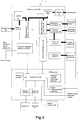
- the present invention provides an on-site full-automatic pressure calibration instrument, comprising: a housing 9; a gas pressure generation unit 1, a pressure control unit 2, an electric signal detection unit 5, a power supply unit 3, and a pressure detection unit 4 assembled respectively within the housing 9; a display 91, a keyboard 92, electric signal output ports 93 appropriately distributed for convenient use, a power switch 94 and a RS232 interface 95, etc.
- the gas pressure generation unit 1 is proivded with a gas path input port (inlet port) 96 communicating with the atmosphere, and an output port communicating with the pressure control unit 2;
- the pressure control unit 2 has a gas path output port 29 communicating with the pressure detection unit 4 (the thick lines in Fig. 2 indicating gas path connections), and is connected respectively with the gas pressure generation unit 1, the pressure detection unit 4, and the electric signal detection unit 5 through signal lines (the thin lines in Fig.
- the power supply unit 3 is connected respectively with the gas pressure generation unit 1, the pressure control unit 2, the pressure detection unit 4, and the electric signal detection unit 5 through electric wires (the medium-thickness lines in Fig. 2 indicating power supply line connections) for power supply.
- the gas pressure generation unit 1 generates gas pressure by a gas pressurizing pump.
- the gas pressurizing pump directly communicates with the atmosphere, and generates gas pressure through compressing air without an externally connected gas cylinder.
- any gas pump that can generate gas pressure through compressing air is applicable in the present invention.
- a gas pressurizing pump developed by the applicant is preferably used, which has functional properties of automatic pressuriaton, high pressure of pressurization, and high efficiency of pressurization, and uses a technique of high-pressure one-way valve.
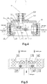
- the gas pressurizing pump used in the present invention is a high pressure bidirectional miniature electric gas pump (miniature pressure pump), the structure of which is shown in Fig. 4 , and which comprises a motor 11, an eccentric shaft 12, a swing rod 13, a pump body 14, a left cylinder body 15 and a right cylinder body 15', one-way valve bodies 16 and a piston rod 10.
- the pump body 14 is a connecting member.
- the motor 11 is fixed to the pump body 14 by a motor bracket 112, with a motor shaft extending downwardly into the pump body 14 via a coupling 113 and connected with the eccentric shaft 12.
- the eccentric shaft 12 is of a cylindrical shape and has a driving pin 121 deviated from the axis at one end thereof, with the driving pin 121 extending through a mounting hole in the flat-shaped swing rod 13.
- a screw 111 extends through another mounting hole in the swing rod 13 to couple the swing rod 13 to the horizontally directioned piston rod 10, with a gap between the swing rod 13 and the piston rod 10 being self-adjustable through a mounting distance given by the screws 111.
- the piston rod 10 is of a cylindrical structure, with sealing rings 19 mounted at opposite ends thereof. The opposite ends of the piston rod 10 extend into the left cylinder body 15 and the right cylinder body 15', respectively.
- the cylinder body is of a cylindrical structure, and the two cylinder bodies 15 and 15' are mounted at opposite ends of the pump body 14, respectively.
- the piston rod 10 forms sealing, through the sealing rings 19 mounted at the opposite ends thereof, at an inner wall of the cylinder bodies 15 and 15'.
- the two cylinder bodies 15 and 15' are sequentially provided at outer ends thereof with cylinder head gaskets 18, the one-way valve bodies 16, and cylinder heads 17 fixedly mounted at the opposite ends of the pump body 14, where two one-way valve bodies 16 are mounted in mutually reverse directions, respectively at each of the opposite ends of the pump body 14.
- the one-way valve bodies 16 communicates with inner cavities of the cylinder bodies 15 and 15', and communicates with external air or compressed air lines through passages in the cylinder heads 17.
- the one-way valve bodies 16 are mounted in the same gas inlet and outlet directions as those shown in Figs. 4 and 5 .
- the cavity seal body 161 is of an annular structure, is an outer support and seal for the whole structure, is disposed between two planes to be sealed (between the cylinder head and the cylinder body), forms a sealed cavity, also used as a seal for the overall structure, and is made of elastic material;
- the elastic arm 162 is of a strip-like structure extending inwardly from the cavity seal body 161, and can be stretched and retracted by its rubber elasticity, with a bottom of the elastic arm 162 abutting against a top of the metal pad 163;
- the metal pad 163 is disc-shaped, having an upper annular slot 131 for embedding an extended end of the elastic arm 162 such that it is engaged into the slot 131 and that a bottom surface of the elastic arm 162 abuts against the top of the metal pad 163, and the metal pad 163
- the one-way valve body 16 is of gas inlet and outlet directions consistent with those of the miniature pressure pump 1 (shown in Fig. 4 ), forming one-way inlet gas.
- the piston 10 in the cylinder body 15 moves leftward to compress gas within the cylinder, and an one-way valve 16 mounted at a lower side is operated, pushing a side of the metal pad 163 embeded with the O-ring 164 to move (in the gas outlet direction) along with the sealing ring.
- the one-way valve body 16 is in an open state, and the compressed high pressure gas is pushed into a high pressure gas output pipe through a gas passage.
- the elastic arm 162 causes the metal pad 163 to move backward (in an opposite direction to the gas inlet direction), compressing the sealing ring 164 so as to form a surface sealing, such that the high pressure gas is enclosed in the desired cavity, and a requirement of high pressure closure is fulfilled.
- the piston 10 in the cylinder body 15 moves rightward to form a negative pressure with gas in the cylinder, and an one-way valve 16 mounted at an upper side is operated, pushing a side of the metal pad 163 embeded with the O-ring 164 to move (in the gas outlet direction of Fig. 5 ) along with the sealing ring.
- the one-way valve body 16 is in an open state, and the external air is intaken into the cylinder body 15 through a gas passage.
- the cavity seal body 161 isolates the high pressure gas from the external environment, while supporting through the elastic arm 162 connected thereto the metal pad 163 and the sealing ring 164, thereby forming an integrated sealing. Since at each end of the pump body 14 are mounted two one-way valve bodies 16 in mutually opposite orientations with one for intake control and the other for exhaust control, an one-direction gas movenment is formed during the reciprocating motion of the piston 10, and compressed gas is generated when gas is placed in the closed spaces.
- the motor 11 drives the eccentric shaft 12 to rotate, and the driving pin on the eccentric shaft 12 pulls the piston rod 10 through the swing rod 13 and the screw 111, so that the piston rod 10 can reciprocate.
- the piston rod 10 forms sealing with the cylinder body 15 through the sealing rings 19 mounted at the opposite ends thereof.
- a process of generating high pressure gas will now be described, taking the left part of the cylinder as an example.
- the piston rod 10 moves rightward, the inner space of the left cylinder body 15 increases rapidly, forming a negative pressure inside the cylinder body 15, so that the upper left one-way valve body 16 is placed in an intake state (the reversely disposed one-way valve core is opened), and the external air is intaken into the cylinder body 15.
- the gas pressure generation unit 1 is a high pressure generation end in the present invention, It uses the miniature pressure pump to intake air from outside, compress the air and exhaust the compressed gas through the pipe to generate high pressure. It then cooperates with a pressure controller and a pressure standard device to implement real-time measurement and transmission of pressure. Through automatic measurement and regulation of the pressure, a certain accurate gas pressure is generated or produced at a pressure output port, as a standard pressure provided for pressure instruments to be calibrated.
- the pressure control unit 2 achieves control of gas pressure through a pressure controller and a single-chip microcomputer (SCM) system.
- a gas path portion of the pressure controller includes an intake valve 21, a buffer 22, a micro-pressure adjusting mechanism 23, an exhaust valve 24 (refer to Fig. 1 for layout position), a muffler 25, and a standard pressure output port 29.
- the standard pressure output port 29 is connected in parallel with a pressure connector 27 of a calibrated gauge and a pressure connector 26 of a pressure standard device.
- the pressure standard device is a standard gauge
- the standard gauge 60 is directly connected to the pressure connector 26, and by manual replacement of a standard gauge 60 of a different range, calibration is performed on a gauge to be calibrated of a corresponding range.
- the pressure standard device is a pressure module (pressure sensor)
- the pressure connector 26 is communicated with pressure modules 61 or 62 respectively by a plurality of solenoid valves 31 or 32, and is switched to the pressure module 61 or 62 of a different range through a valve switching circuit 30.
- the above components are communicated respectively via gas paths (the thick lines in Fig. 3 indicating gas paths).
- a control portion of the pressure controller 2 includes a pressure regulation driving circuit 20 and the valve switching circuit 30.
- the SCM system comprises a control chip 28 loaded with a pressure control algorithm and an electric signal (voltage, current) algorithm, and is provided with a plurality of interfaces, such as a digital communication interface (connected to the standard gauge 60 or connected to the pressure modules 61 and 62 via a sensor switching element), a display interface (connected to the display 91), a keyboard interface (connected to the keyboard 92), and a RS232 interface 95 to facilitate connections with external devices when necessary, and the like.
- the pressure regulation driving circuit 20 is connected to the power supply unit via a power supply line (indicated by the medium-thickness lines in Fig.
- the pressure regulation driving circuit 20 is further connected to the motor 11 of the miniature pressure pump via a signal line to control operations thereof.
- the valve switching circuit 30 is connected to the plurality of solenoid valves 31 and 32 and the control chip 28 via signal lines (indicated by the thin lines in Fig. 3 ) to control operations of the pressure modules through opening and closing of the solenoid valves.
- the intake valve 21 is communicated with the high pressure gas output pipe of the miniature pressure pump 1 and functions as a pressure input port to the pressure controller.
- a pressure output port 29 of the pressure controller is the two pressure connectors 26, 27 connected in parallel.
- the buffer 22 is a pressure accommodating chamber of a fixed shape (e.g., an elliptical cylinder shape), mainly used to filter fluctuations in air flow entering through the intake valve 21, stabilize and preserve gas pressure.
- the gas passing through the buffer 22 enters the micro-pressure adjusting mechanism 23.
- the micro-pressure adjusting mechanism 23 comprises a cylinder and a plunger installed in the cylinder. The plunger is connected with a screw mechanism (reference can be made to the Chinese Patent No.
- the pressure connectors 26, 27 and the exhaust valve 24 are connected in parallel via gas paths to ensure the same output pressure.
- the control functions of the pressure regulation driving circuit 20 are performed under the drive of the control chip 28 of the SCM system, mainly to implement electric control on the open/close state of the intake valve 21 and the exhaust valve 24, so as to achieve regulation on gas inflow or discharge pressure, and to implement control on the displacement of the plunger within the micro-pressure adjusting mechanism 23 by controlling the feed of the screw mechanism, so as to achieve regulation on the output pressure by changing the volume of gas compression in the cylinder.
- the SCM system includes the embedded control chip 28, and the display interface, the keyboard interface and the digital communication interface, and may also be provided with a RS232 interface 95.
- the control chip 28 is embedded therein with a pressure control algorithm (such as the well-known special adaptive PID control algorithm) and an electric signal (voltage, current) algorithm.
- the digital communication interface of the SCM system when the pressure standard device is a standard gauge, can directly receive a pressure value displayed and returned by the standard gauge 60. However, when the pressure standard device is a plurality of pressure modules (of different ranges), through a module switching element (e.g., a locator), a pressure value of the located pressure module 61 or 62 is returned to the control chip 28 through the digital communication interface.
- the pressure control algorithm calculates a control amount based on the difference value, and then transmits the calculated control amount to the pressure regulation driving circuit 20.
- the pressure regulation driving circuit 20 thus achieves control on the intake valve 21, the exhaust valve 24 and the micro-pressure adjusting mechanism 23, thereby implementing a feedback control in which pressure occurs precisely.
- the control chip 28 as well as the pressure regulation drivng circuit 20, the valve switching circuit 30 and the pressure standard device 6 constitute a pressure output control unit for real-time control of pressure output.
- the control chip 28 as well as the pressure regulation drivng circuit 20, the calibrated instrument 7, and the external display 91 and keyboard 92 of the SCM system constitute a pressure measurement and control unit, wherein set pressures and programmable operation data and parameters are input through the keyboard 92, and pressure control results and curves are displayed through the standard gauge 60 or the display 91.
- the control chip 28 is further connected to the electric signal detection unit 5, to implement detection and calibration on output signals of the calibrated gauge (refer to Fig. 3 , the thin lines indicating signal connections).
- the RS232 interface 95 is reserved for use in conditional detection environments, and can be connected with other external devices, such as an external computer (refer to Fig. 2 ), a printer, etc.
- the operation of the pressure control unit 2 is as follows.
- a pressure value is set according to the range of a pressure gauge 7 to be calibrated, and is used as a set pressure control value.
- the pressure control value is input to the control chip 28 via the keyboard 92.
- the pressure regulation drivng circuit 20 drives the motor 11 of the miniature pressure pump to operate thereby generating high pressure gas.
- a value is read out through the standard gauge 60 connected to the pressure coonector 26 (or recorded by a pressure sensor 61 or 62, a range of which matches that of the pressure gauge 7 to be calibrated, and which is selected through the valve switching circuit 30), and the output pressure value is returned to the control chip 28.
- the control chip 28 compares the output pressure with the pressure control value, calculate a control amount based on the difference value, and transmits the calculated control amount to the pressure regulation driving circuit 20.
- the pressure regulation driving circuit 20 performs control on the intake valve 21, the exhaust valve 24 and the micro-pressure adjusting mechanism 23. Until the output pressure value is equal to the set pressure control value, the precise control of the output pressure is completed.
- the pressure control unit performs setting control on the gas pressure, and outputs an accurate gas pressure at the pressure output port. Based on the accurately output gas pressure value, an accurate pressure calibration is carried out on the pressure gauge to be calibrated.
- the power supply unit 3 is primarily a battery pack equipped in the instrument. It can maintain power supply without an external power source at the same time, making it possible to be carried to field. In case power is available in the field, the power supply unit may also be connected to an external power source (refer to Fig. 2 ), and supply power by the external power source. In addition, the external power source can also charge the battery pack.
- the battery pack power supply unit used in the present invention may be a conventional DC power supply system, preferably a power supply system with functions of battery power supply monitoring, control and protection, as well as battery pack power supply and charge control.
- Used herein is the power supply/charge control circuit disclosed in the Chinese Patent No. ZL200620119089.4 , "Power supply/charging control circuit," as shown in Fig. 6 , in which circuit the AC/DC power supply terminal is connected to an external power source, and the instrument power supply terminal is the current output terminal. Power is transmitted respectively to other units in the pressure calibrator, as shown in Fig. 2 .
- the power supply unit can ensure good DC power supply performance, no power supply interruption, good battery charging performance, safe use of battery, and extended life span. When used in the pressure calibrator, it enables the pressure calibrator to be accurate in detection, safe and reliable, of long operating time, and convenient to be carried for field application.
- the pressure detection unit 4 includes pressure standard devices of at least two ranges so as to be able to perform calibration on calibrated gauges of different ranges.
- the pressure standard device 6 is attached to one pressure connector 26 at the pressure output port 29 of the pressure controller, and the calibrated gauge 7 is attached to the other pressure connector 27 at the pressure output port 29 of the pressure controller.
- the pressure standard device 6 can be a precision digital pressure gauge, a digital pressure calibrator, an (absolute pressure) digital pressure gauge, or an intelligent digital pressure calibrator, collectively called standard gauge 60, but it may also be a pressure module (pressure sensors 61 and 62). In case of the standard gauge, a plurality of standard gauges with different ranges need to be equipped, and replaced manually at the pressure connector 26.
- a plurality of pressure modules 61 and 62 may be fixedly arranged amd communicated with the pressure connector 26 via the respectively connected solenoid valves 31 or 32.
- the pressure standard device 6 (standard gauge or pressure module) is attached to the pressure connector 26, and for different pressure ranges, the pressure standard device is replaced with one of corresponding range (as shown in Fig. 1 , a pressure module may be used and communication indicated by the solid line, or alternatively a standard gauge may be used and communication indicated by the broken line), so that the range of pressure measurement and control is not limited, and the measurement accuracy is not affected by the measurement range.
- the pressure standard device 6 is in signal connection with the pressure controller (refer to Fig.
- the electric signal detection unit 5 When using the standard gauge 60 as the pressure standard device 6, a digital pressure calibrator (a previous invention patent of the company, Chinese Patent No. ZL200610114103.6 ) can be used as the standard gauge.
- the digital pressure calibrator is provided with an electric signal detection function, which is combined with the control chip 28 of the pressure control unit 2 to perform detection and calibration on electric signals output by the calibrated gauge while performing pressure calibration on it, thereby implementing integrated calibration on pressure and electric signals, and achieving full-automatic pressure calibration.
- a standard electric signal detection circuit is provided to measure electric signals output by the pressure gauge, and is integrated with the pressure sensors and the pressure controller to perform detection and calibration on electric signals output by the calibrated gauge while performing pressure calibration on it, thereby implementing integrated calibration on pressure and electric signals, and achieving portable full-automatic pressure calibration.
- the electric signal detection circuit is shown in Fig. 7 .
- the pressure switch signal input terminal 71 and the electric signal input terminal 72 are connected to a signal amplifier 52, respectively, to input the generated electric signals to the signal amplifier 52.
- an electric signal is input to an A/D converter 51 connected thereto, and is then converted into a digital signal through the A/D converter 51, the digital signal in turn is input to the control chip 28 connected thereto.
- the detected electric signal value may used not only as a display value of the electric signal output by the pressure instrument, but also as a calibration value for the electric signal output by the pressure instrument, and is used to determine the accuracy of the electric signal value output by the pressure instrument with respect to the standard value, or used to determine the consistency of the electric signal value output by the pressure instrument with a prescribed value.
- Electric signal calibration data will also be stored in a memory of the controller chip 28.
- the on/off signal information of the pressure switch is also used in the control chip for program determination on pressure output values measured at a corresponding state.
- an input protection circuit 53 is specifically added. Each input electric singal is protected by the input protection circuit 53, and then enters the signal amplifier 52 and the A/D converter 51, so as to avoid damage to the circuit.
- the principle of the input protection circuit 53 is that, when a problem occurs in the input signal, an impedance of the input protection circuit 53 will change to form a protective circuit, so as to prevent a too strong electric signal from damaging the signal amplifier 52 and the A/D converter 51, and when the input signal is removed, the input protection circuit 53 will restore the original impedance state.
- the input protection circuit 53 can be commercially availble.
- the standard electric signal detection circuit of the electric signal detection unit 5 implements measurement, calibration or detection of high accuracy on the electric signals (current, voltage, switch pulse, etc.) output by the calibrated pressure instrument.
- the electric signal calibration and detection results and curves are displayed by the display.
- the housing is interconnected and assembled in the housing, the placement of which is not particular limited (shown in Fig. 1 is only a specific form of assembly), subject to the convenience of use.
- the display, the keyboard and the power switch, the signal output ports, and the RS232 interface, etc. can be directly provided on the surface of the housing, and the inlet port 96 of the high pressure gas generating unit 1, the exhaust port 24 of the pressure controller 2, the pressure connector 26 along with the pressure standard device 6, and the pressure connector 27 along with the calibrated gauge 7 can be extended, respectively, out of the housing 9.
- the housing may further be provided with accessories such as covers, handles, straps, etc. for convenience of carry, thereby forming a compact, portable on-site full-automatic pressure calibration instrument.
- the on-site full-automatic pressure calibration instrument ot the present invention does not require external gas cylinders.
- the gas pressure generation unit generates compressed air and input the same into a closed pressure calibration pipe of the pressure controller.
- the gas pressure control unit performs automatic measurement and regulation on the auto-generated gas pressure.
- a certain accurate gas pressure is output as a standard pressure provided to the pressure instrument to be. calibrated.
- measurement and calibration of high accuracy is implemented.
- the instrument uses its own battery for power supply, requiring no external AC power source.
- the full-automatic pressure calibration instrument achieves automated calibration of pressure instruments and significantly improves working efficiency while greatly reducing its own weight and volume.
- the instrument can be conveniently carried to field, and can implement on-site calibration on a large number of field used pressure instruments.
Landscapes
- Engineering & Computer Science (AREA)
- Mechanical Engineering (AREA)
- General Engineering & Computer Science (AREA)
- Physics & Mathematics (AREA)
- General Physics & Mathematics (AREA)
- Chemical & Material Sciences (AREA)
- Analytical Chemistry (AREA)
- Fluid Mechanics (AREA)
- Automation & Control Theory (AREA)
- Measuring Fluid Pressure (AREA)
Claims (11)
- Bidirektionale elektrische Miniatur-Hochdruckgaspumpe (1) mit einem Motor (11), einer exzentrischen Welle (12), einer Schwingstange (13), einem Pumpenkörper (14), einem linken Zylinderkörper (15) und einem rechten Zylinderkörper (15'), einer Kolbenstange (10), und einem Einweg-Ventilkörper (16), wobei an jedem der Zylinderkörper ein Zylinderkopf (17) befestigt ist,
der Pumpenkörper (14) ein Verbindungsglied ist, der Motor (11) an dem Pumpenkörper (14) befestigt ist, und eine Motorwelle in den Pumpenkörper (14) hineinragt und mit der exzentrischen Welle (12) verbunden ist, und
jeder der Zylinderkörper (15, 15') eine zylindrische Struktur hat und der Reihe nach an seinem äußeren Ende mit dem Einweg-Zylinderkörper (16) und dem Zylinderkopf (17) versehen ist, wobei der Einweg-Zylinderkörper (16) an einer Innenseite des Zylinderkopfs (17) angebracht ist und mit einem inneren Hohlraum des Zylinderkörpers (15, 15') in Verbindung steht, dadurch gekennzeichnet, dass,
die exzentrische Welle (12) eine zylindrische Form und an einem Ende einen Antriebsstift (121) hat, der von der Motorwellenachse ausgeht, hat, wobei der Antriebsstift (121) sich durch ein Montageloch in der flach ausgebildeten Schwingstange (13) erstreckt, die unter der exzentrischen Welle (12) angeordnet ist,
die Schwingstange (13) mit der horizontal unter ihr angeordneten Kolbenstange (10) durch eine Schraube (111) verbunden ist, wobei zwischen der Schwingstange (13) und der Kolbenstange (10) ein Spalt ist,
die Kolbenstange (10) eine zylindrische Form hat und an ihren gegenüberliegenden Enden mit Dichtringen (19) versehen ist und sich in den linken und den rechten Zylinderkörper (15, 15') hinein erstreckt, wobei die Dichtringe (19) an die Innenwände der Zylinderkörper (15, 15') angepasst sind, die beiden Zylinderkörper (15, 15') fest an gegenüberliegenden Enden des Pumpenkörpers (14) montiert sind und die Kolbenstange (10) darin horizontal als eine Achse liegt, und
der Einweg-Zylinderkörper (16) mit Umgebungsluft oder Druckluftleitungen über Durchgänge im Zylinderkopf (17) in Verbindung steht. - Bidirektionale elektrische Miniatur-Hochdruckgaspumpe (1) nach Anspruch 1, dadurch gekennzeichnet, dass die Kolbenstange (10) an den Innenwänden der Zylinderkörper (15, 15') durch die Dichtungsringe (19), die an ihren gegenüberliegenden Enden montiert sind, Abdichtung bewirkt, und eine Schwingbewegung der Schwingstange (13) die Kolbenstange (10) antreibt, um sich zwischen den beiden Zylinderkörpern entlang der Achse hin und her zu bewegen.
- Bidirektionale elektrische Miniatur-Hochdruckgaspumpe (1) nach Anspruch 1 oder 2, dadurch gekennzeichnet, dass der Spalt zwischen der Schwingstange (13) und der Kolbenstange (10) durch die Schraube (111) eingestellt ist.
- Bidirektionale elektrische Miniatur-Hochdruckgaspumpe (1) nach Anspruch 1 oder 2 oder 3, dadurch gekennzeichnet, dass das äußere Ende des Zylinderkörpers (15, 15') an oberen und unteren Positionen mit zwei umgekehrt angeordneten Einweg-Ventilkörpern (16) montiert ist, wobei einer der Einweg-Ventilkörper (16) mit der Umgebungsluft zum Aufnehmen von Umgebungsluft in Verbindung steht und der andere der Einweg-Ventilkörper (16) mit der Druckluftleitung zum Abgeben von Hochdruckgas in Verbindung steht.
- Bidirektionale elektrische Miniatur-Hochdruckgaspumpe (1) nach Anspruch 4, dadurch gekennzeichnet, dass eine Zylinderkopfdichtung (18) zwischen dem Einweg-Ventilkörper (16) und dem Zylinderkörper (15, 15') angeordnet ist.
- Bidirektionale elektrische Miniatur-Hochdruckgaspumpe (1) nach Anspruch 4 oder 5, dadurch gekennzeichnet, dass der Einweg-Ventilkörper (16) durch Zusammenbau eines Hohlraumdichtkörpers (161), eines elastischen Arms (162), eines Metallklotzes (163) und eines Dichtrings (164) gebildet ist, wobei der elastische Arm (162) sich von dem Hohlraumdichtkörper (161) aus nach Innen erstreckt und mit einem oberen Ende des Metallklotzes (163) gekoppelt ist und in ein unteres Ende des Metallklotzes (163) der Dichtring (164) fest eingebettet ist.
- Bidirektionale elektrische Miniatur-Hochdruckgaspumpe (1) nach Anspruch 6, dadurch gekennzeichnet, dass der Hohlraumdichtkörper (161) eine ringförmige Struktur hat, als eine äußere Stütze und Dichtung der Gesamtstruktur dient, aus elastischem Material hergestellt ist und zwischen dem Zylinderkopf (17) und dem Zylinderkörper (15, 15') zum Abdichten des Gaskanals zwischen dem Zylinderkopf (17) und dem Zylinderkörper (15, 15') angeordnet ist.
- Bidirektionale elektrische Miniatur-Hochdruckgaspumpe (1) nach Anspruch 6 oder 7, dadurch gekennzeichnet, dass der elastische Arm (162) in den Hohlraumdichtkörper (161) integriert ist, eine streifenartige Form hat, die sich einwärts erstreckt, und aus elastischem Material hergestellt ist.
- Bidirektionale elektrische Miniatur-Hochdruckgaspumpe (1) nach Anspruch 6, 7 oder 8, dadurch gekennzeichnet, dass der Metallklotz (163) eine Scheibenform hat und an einem oberen Abschnitt mit einem ringförmigen Schlitz (131) versehen ist, in den ein Ende des elastischen Arms (162) eingreift.
- Bidirektionale elektrische Miniaturhochdruckgaspumpe (1) nach einem der Ansprüche 6 bis 9, dadurch gekennzeichnet, dass der Metallklotz (163) an einem unteren Abschnitt mit einer Ringnut (132) versehen ist, in welcher der Dichtring (164) festgelegt ist.
- Bidirektionale elektrische Miniaturhochdruckgaspumpe (1) nach Anspruch 10, dadurch gekennzeichnet, dass der Dichtring (164), der in der Nut (132) festgelegt ist, auf einem Gasdurchgang zwischen dem Zylinderkopf (17) und dem Zylinderkörper (15, 15') angeordnet ist.
Applications Claiming Priority (2)
| Application Number | Priority Date | Filing Date | Title |
|---|---|---|---|
| CN2011101390646A CN102252805B (zh) | 2011-05-26 | 2011-05-26 | 多量程现场全自动压力及电信号校验仪 |
| EP11866180.0A EP2717031B1 (de) | 2011-05-26 | 2011-07-27 | Vollautomatisches mehrbereichsfeldinstrument zur kalibrierung von druck und elektrischen signalen |
Related Parent Applications (2)
| Application Number | Title | Priority Date | Filing Date |
|---|---|---|---|
| EP11866180.0A Division EP2717031B1 (de) | 2011-05-26 | 2011-07-27 | Vollautomatisches mehrbereichsfeldinstrument zur kalibrierung von druck und elektrischen signalen |
| EP11866180.0A Division-Into EP2717031B1 (de) | 2011-05-26 | 2011-07-27 | Vollautomatisches mehrbereichsfeldinstrument zur kalibrierung von druck und elektrischen signalen |
Publications (2)
| Publication Number | Publication Date |
|---|---|
| EP2944937A1 EP2944937A1 (de) | 2015-11-18 |
| EP2944937B1 true EP2944937B1 (de) | 2016-12-14 |
Family
ID=44980202
Family Applications (3)
| Application Number | Title | Priority Date | Filing Date |
|---|---|---|---|
| EP15175217.7A Active EP2944937B1 (de) | 2011-05-26 | 2011-07-27 | Bidirektionale elektrische miniatur-hochdruckgaspumpe |
| EP15175220.1A Active EP2944938B1 (de) | 2011-05-26 | 2011-07-27 | Vollautomatisches instrument zur druckkalibrierung vor ort für mehrere bereiche |
| EP11866180.0A Active EP2717031B1 (de) | 2011-05-26 | 2011-07-27 | Vollautomatisches mehrbereichsfeldinstrument zur kalibrierung von druck und elektrischen signalen |
Family Applications After (2)
| Application Number | Title | Priority Date | Filing Date |
|---|---|---|---|
| EP15175220.1A Active EP2944938B1 (de) | 2011-05-26 | 2011-07-27 | Vollautomatisches instrument zur druckkalibrierung vor ort für mehrere bereiche |
| EP11866180.0A Active EP2717031B1 (de) | 2011-05-26 | 2011-07-27 | Vollautomatisches mehrbereichsfeldinstrument zur kalibrierung von druck und elektrischen signalen |
Country Status (4)
| Country | Link |
|---|---|
| US (3) | US9395261B2 (de) |
| EP (3) | EP2944937B1 (de) |
| CN (1) | CN102252805B (de) |
| WO (1) | WO2012159232A1 (de) |
Families Citing this family (65)
| Publication number | Priority date | Publication date | Assignee | Title |
|---|---|---|---|---|
| JP5700348B2 (ja) * | 2011-09-20 | 2015-04-15 | 独立行政法人産業技術総合研究所 | 圧力計校正装置 |
| CN102494841A (zh) * | 2011-12-26 | 2012-06-13 | 潍柴动力股份有限公司 | 一种压力传感器标定系统 |
| CN103234697A (zh) * | 2013-04-24 | 2013-08-07 | 南京化工职业技术学院 | 中压压力仪表校验仪 |
| CN103267608A (zh) * | 2013-05-31 | 2013-08-28 | 南京化工职业技术学院 | 便携式压力仪表校验仪 |
| CN103528756A (zh) * | 2013-09-27 | 2014-01-22 | 南京化工职业技术学院 | 全自动压力变送器校验仪 |
| CN103712742B (zh) * | 2013-12-18 | 2015-12-02 | 安徽睿联汽车传感器工程技术有限公司 | 一种压力检测电路 |
| CN103808460B (zh) * | 2014-03-26 | 2015-10-14 | 北京航空航天大学 | 压力传感器静态性能快速校准方法 |
| CN104165728A (zh) * | 2014-09-01 | 2014-11-26 | 北京斯贝克科技有限责任公司 | 一种高准确度压力控制器 |
| CN104296923B (zh) * | 2014-09-22 | 2017-01-25 | 广东合微集成电路技术有限公司 | 一种晶圆级传感器的测试方法 |
| CN104330210A (zh) * | 2014-10-30 | 2015-02-04 | 北京航天计量测试技术研究所 | 多孔转轮结构方波压力发生器 |
| TWI568931B (zh) * | 2015-04-24 | 2017-02-01 | Inflatable device with double pressure gauge | |
| CN105136407A (zh) * | 2015-08-27 | 2015-12-09 | 浙江联宜电机有限公司 | 蜗轮减速箱气密性测试设备 |
| CN105380628B (zh) * | 2015-11-02 | 2018-03-02 | 山东省医疗器械产品质量检验中心 | 一种基于压力动态平衡的静态压力准确性测试装置及测试方法 |
| GB2544336B (en) * | 2015-11-13 | 2020-09-16 | Sonardyne Int Ltd | In-situ pressure sensor bias determination apparatus, subsea sensor node apparatus and method of determining a bias of a pressure sensing apparatus |
| WO2018014790A1 (zh) * | 2016-07-22 | 2018-01-25 | 北京康斯特仪表科技股份有限公司 | 一种手持全自动压力校验仪 |
| CN106370875A (zh) * | 2016-11-02 | 2017-02-01 | 南京泰克奥科技有限公司 | 一种压力体积控制器 |
| CN108120550A (zh) * | 2016-11-30 | 2018-06-05 | 北京航天计量测试技术研究所 | 一种高压气体压力现场校准方法 |
| JP6426764B2 (ja) * | 2017-01-16 | 2018-11-21 | 横河電機株式会社 | 圧力測定器 |
| CN107063563A (zh) * | 2017-03-30 | 2017-08-18 | 江苏方天电力技术有限公司 | 一种电磁阀控制的多量程压力检测装置 |
| WO2019011353A1 (zh) | 2017-07-14 | 2019-01-17 | 北京康斯特仪表科技股份有限公司 | 压力校准装置及压力仪表校准信息的处理方法 |
| CN107390159B (zh) * | 2017-07-31 | 2022-08-23 | 国网山东省电力公司青州市供电公司 | 电能表校表装置及其使用方法 |
| CN107607251B (zh) * | 2017-09-08 | 2024-05-14 | 上海工业自动化仪表研究院有限公司 | 一种具有双量程的差压或压力变送器 |
| CN107860512B (zh) * | 2017-12-13 | 2024-06-04 | 贵州航天计量测试技术研究所 | 一种阶跃压力连续可控的压力传感器校准装置及校准方法 |
| CN108223348B (zh) * | 2017-12-29 | 2020-01-24 | 凯龙高科技股份有限公司 | 一种scr计量泵下线测试台 |
| US11002262B2 (en) * | 2018-02-26 | 2021-05-11 | Valco Instruments Company, L.P. | Pump for liquid chromatography with pressure sensor |
| CN108362438B (zh) * | 2018-04-16 | 2025-03-21 | 合肥市贵谦信息科技有限公司 | 一种陶瓷压力传感器信号检测用检具 |
| CN108956008B (zh) * | 2018-09-12 | 2024-08-13 | 内蒙古自治区计量测试研究院 | 一种智能化多通道检定系统及检定方法 |
| CN111103090A (zh) * | 2018-10-25 | 2020-05-05 | 北京振兴计量测试研究所 | 舵机测试系统扭矩校准装置 |
| CN109163844B (zh) * | 2018-10-31 | 2023-09-22 | 江苏方天电力技术有限公司 | 一种数字压力校验箱 |
| CN109238556B (zh) * | 2018-11-06 | 2021-03-30 | 马鞍山市浩宇仪表有限公司 | 一种易拆装防撞击数显气压表 |
| CN109323717A (zh) * | 2018-11-20 | 2019-02-12 | 天津智易时代科技发展有限公司 | 一种便携式气体动态校准仪 |
| CN109900427B (zh) * | 2019-04-15 | 2024-06-04 | 上海市计量测试技术研究院 | 一种用于电测式压力计的自动校准系统及校准方法 |
| CN110146221A (zh) * | 2019-06-04 | 2019-08-20 | 江苏方天电力技术有限公司 | 一种压力测量监视系统的在线检测装置 |
| CN112082693A (zh) * | 2019-06-14 | 2020-12-15 | 北京振兴计量测试研究所 | 稳定气压发生装置 |
| CN112304494B (zh) * | 2019-07-25 | 2024-07-16 | 北京康斯特仪表科技股份有限公司 | 一种气路组件及气体压力校验仪 |
| CN111173726A (zh) * | 2020-01-17 | 2020-05-19 | 成都航空职业技术学院 | 一种微小流量注射泵检定方法 |
| CN111751048A (zh) * | 2020-06-30 | 2020-10-09 | 中国航发动力股份有限公司 | 一种配套数字仪表的压力传感器在线校检装置及方法 |
| CN111937835A (zh) * | 2020-07-10 | 2020-11-17 | 北京农业智能装备技术研究中心 | 基于超声传感的果园风袋式对靶喷雾机及方法 |
| CN112033601A (zh) * | 2020-08-03 | 2020-12-04 | 昆明云内动力股份有限公司 | 一种用于柴油机的压力传感器检测系统 |
| CN112161741B (zh) * | 2020-09-18 | 2025-04-29 | 北京康斯特仪表科技股份有限公司 | 压力回零器、连接装置、校验系统及压力自动回零方法 |
| CN112197901B (zh) * | 2020-10-10 | 2025-06-03 | 南方电网调峰调频发电有限公司检修试验分公司 | 一种压力开关传感器检测装置及检测方法 |
| CN112179559A (zh) * | 2020-10-23 | 2021-01-05 | 南京爱尔传感科技有限公司 | 一种基于陶瓷压力传感器的压力变送器 |
| CN113397478B (zh) * | 2020-11-09 | 2022-05-17 | 华东理工大学 | 一种用于脉诊装置的自动加压控制方法 |
| CN112903186B (zh) * | 2021-02-24 | 2022-09-27 | 北京康斯特仪表科技股份有限公司 | 压力校准方法及压力校准装置 |
| CN113029434B (zh) * | 2021-03-09 | 2022-07-15 | 江南大学 | 压力仪表测量精度检测用液体介质的压力控制系统的控制方法 |
| CN113029433B (zh) * | 2021-03-09 | 2022-05-17 | 江南大学 | 压力仪表测量精度检测用气体介质的压力控制系统及方法 |
| CN113188714A (zh) * | 2021-03-11 | 2021-07-30 | 岳建疆 | 一种蓝牙数字压力表快速自动化检测检验装置 |
| CN115265906B (zh) * | 2021-04-30 | 2025-03-18 | 中国石油天然气集团有限公司 | 一种由壬式压力变送器检测液压式自动锁紧装置及其锁紧方法 |
| CN113218434B (zh) * | 2021-05-07 | 2025-07-11 | 北京康斯特仪表科技股份有限公司 | 手持校验仪器及其制造方法 |
| CN113776729A (zh) * | 2021-09-09 | 2021-12-10 | 江西万年芯微电子有限公司 | 一种压力传感器可靠性测试系统 |
| CN114370983B (zh) * | 2021-12-29 | 2022-12-02 | 卫圣康医学科技(江苏)有限公司 | 一种用于顺应性检测的校准方法及测试方法 |
| CN114553214B (zh) * | 2022-04-21 | 2022-07-15 | 新港海岸(北京)科技有限公司 | 一种电平自动切换电路、方法及系统 |
| CN115097075A (zh) * | 2022-06-29 | 2022-09-23 | 昆明理工大学 | 基于Arduino板的氨挥发在线检测装置 |
| CN115371883A (zh) * | 2022-07-12 | 2022-11-22 | 北京中科京仪科技有限公司 | 压力仪表的检测系统及方法 |
| CN115507992A (zh) * | 2022-08-22 | 2022-12-23 | 陕西创威科技有限公司 | 一种高精度微压气体活塞式压力计 |
| CN117664436A (zh) * | 2022-09-07 | 2024-03-08 | 厦门斯科瑞科技有限公司 | 一种电池箱热失控压力探测器的自动测试系统及其控制方法 |
| CN115979323B (zh) * | 2022-12-30 | 2025-02-28 | 北京康斯特仪表科技股份有限公司 | 基于仪表检测系统的仪表检测方法及系统 |
| CN116296058A (zh) * | 2023-03-23 | 2023-06-23 | 安图实验仪器(郑州)有限公司 | 多类型、宽量程压力传感器检测方法 |
| CN116839806A (zh) * | 2023-05-16 | 2023-10-03 | 中国航发沈阳发动机研究所 | 一种航空发动机机载压力传感器盒校准方法 |
| CN116625575A (zh) * | 2023-05-19 | 2023-08-22 | 中国航发沈阳发动机研究所 | 一种压力扫描阀现场校准系统及其方法 |
| CN116793573B (zh) * | 2023-08-21 | 2023-11-28 | 苏州中电科启计量检测技术有限公司 | 一种多路同步校验的压力计检测平台 |
| CN117030109A (zh) * | 2023-08-22 | 2023-11-10 | 安徽京芯传感科技有限公司 | 基于LabVIEW的压力传感器多量程标定系统 |
| CN118089820B (zh) * | 2024-04-28 | 2024-07-09 | 成都中科四点零科技有限公司 | 一种信号校验仪 |
| CN118817143B (zh) * | 2024-09-19 | 2024-11-15 | 宝鸡市兴宇腾电子科技有限公司 | 一种多参量压力表 |
| CN119063910A (zh) * | 2024-11-06 | 2024-12-03 | 杭州鑫高科技有限公司 | 一种压力表检定装置及检定方法 |
Citations (1)
| Publication number | Priority date | Publication date | Assignee | Title |
|---|---|---|---|---|
| EP2405137A2 (de) * | 2010-07-06 | 2012-01-11 | Jongherya Co., Ltd. | Pumpe |
Family Cites Families (26)
| Publication number | Priority date | Publication date | Assignee | Title |
|---|---|---|---|---|
| US3557602A (en) * | 1968-10-15 | 1971-01-26 | White Sales Corp Graham | Pressure gauge testing system |
| CH545916A (de) * | 1971-11-09 | 1974-02-15 | ||
| US4512179A (en) * | 1983-10-28 | 1985-04-23 | General Electric Company | Instrument for calibrating pressure gauges |
| US4658829A (en) * | 1985-10-10 | 1987-04-21 | Utah Medical Products, Inc. | Method and apparatus for pressure transducer calibration and simulation |
| US5076769A (en) * | 1990-07-16 | 1991-12-31 | The Dow Chemical Company | Double acting pump |
| JP2951718B2 (ja) * | 1990-11-28 | 1999-09-20 | 東京エレクトロン株式会社 | 圧力ゲージ出力の零点調整装置 |
| US5319965A (en) * | 1992-03-02 | 1994-06-14 | Halliburton Company | Multiple channel pressure recorder |
| US5837881A (en) * | 1996-12-23 | 1998-11-17 | Martin; Scott | Pressure gauge calibrating device |
| KR100402461B1 (ko) * | 2000-12-08 | 2003-10-22 | 주식회사 엘지이아이 | 밀폐형 압축기의 피스톤핀 설치구조 |
| US6672130B2 (en) * | 2001-09-08 | 2004-01-06 | Dresser, Inc. | Pressure generator for portable instrument |
| CN2511964Y (zh) | 2001-11-09 | 2002-09-18 | 刘天平 | 连接微机的压力传感器校验装置 |
| US6640614B1 (en) | 2002-07-17 | 2003-11-04 | Molon, Inc. | Package burst pressure simulator |
| US7266986B2 (en) * | 2003-11-19 | 2007-09-11 | The United States Of America As Represented By The Secretary Of The Army | Portable system for measuring dynamic pressure in situ and method of employment therefor |
| EP1982155A1 (de) * | 2005-05-26 | 2008-10-22 | Siemens Aktiengesellschaft | Anordnung und verfahren zum prüfen der funktion eines dynamischen gasdrucksensors |
| CN2930059Y (zh) | 2006-08-01 | 2007-08-01 | 北京康斯特仪表科技有限公司 | 一种供电/充电控制电路 |
| CN200941077Y (zh) | 2006-08-30 | 2007-08-29 | 北京康斯特仪表科技有限公司 | 一种气体压力表校验器 |
| CN100535624C (zh) | 2006-10-27 | 2009-09-02 | 北京康斯特仪表科技股份有限公司 | 数字压力校验仪 |
| CN201034785Y (zh) * | 2007-04-19 | 2008-03-12 | 北京康斯特仪表科技有限公司 | 一种液体压力校验器 |
| KR20090025823A (ko) * | 2007-09-07 | 2009-03-11 | 한국표준과학연구원 | 이동없이 가능한 진공게이지의 교정/시험 장치 및 그 방법 |
| US20090068040A1 (en) * | 2007-09-07 | 2009-03-12 | Mann Douglas A | Five-bar compressor |
| CN201107154Y (zh) | 2007-11-20 | 2008-08-27 | 成都市精测科技有限公司 | 压力全自动校验装置 |
| CN201116894Y (zh) * | 2007-11-23 | 2008-09-17 | 江苏杰创科技有限公司 | 分体结构式自动压力校验台 |
| CN201155999Y (zh) | 2007-12-03 | 2008-11-26 | 北京康斯特仪表科技有限公司 | 自动微压力发生器 |
| US8616043B2 (en) * | 2010-04-30 | 2013-12-31 | Applied Materials, Inc. | Methods and apparatus for calibrating pressure gauges in a substrate processing system |
| CN202110034U (zh) * | 2011-05-26 | 2012-01-11 | 北京康斯特仪表科技股份有限公司 | 多量程现场全自动压力及电信号校验仪 |
| CN102305689B (zh) | 2011-05-26 | 2013-04-10 | 北京康斯特仪表科技股份有限公司 | 现场全自动压力及电信号校验仪 |
-
2011
- 2011-05-26 CN CN2011101390646A patent/CN102252805B/zh active Active
- 2011-07-27 WO PCT/CN2011/001232 patent/WO2012159232A1/zh not_active Ceased
- 2011-07-27 US US14/122,087 patent/US9395261B2/en active Active
- 2011-07-27 EP EP15175217.7A patent/EP2944937B1/de active Active
- 2011-07-27 EP EP15175220.1A patent/EP2944938B1/de active Active
- 2011-07-27 EP EP11866180.0A patent/EP2717031B1/de active Active
-
2015
- 2015-07-22 US US14/806,235 patent/US9394895B2/en active Active
- 2015-07-22 US US14/806,196 patent/US10012221B2/en active Active
Patent Citations (1)
| Publication number | Priority date | Publication date | Assignee | Title |
|---|---|---|---|---|
| EP2405137A2 (de) * | 2010-07-06 | 2012-01-11 | Jongherya Co., Ltd. | Pumpe |
Also Published As
| Publication number | Publication date |
|---|---|
| EP2944938B1 (de) | 2017-01-04 |
| US9395261B2 (en) | 2016-07-19 |
| EP2717031A4 (de) | 2014-12-24 |
| US20140182354A1 (en) | 2014-07-03 |
| WO2012159232A1 (zh) | 2012-11-29 |
| EP2717031A1 (de) | 2014-04-09 |
| CN102252805A (zh) | 2011-11-23 |
| US9394895B2 (en) | 2016-07-19 |
| US20150322936A1 (en) | 2015-11-12 |
| EP2944938A1 (de) | 2015-11-18 |
| US10012221B2 (en) | 2018-07-03 |
| US20150323409A1 (en) | 2015-11-12 |
| EP2944937A1 (de) | 2015-11-18 |
| EP2717031B1 (de) | 2020-05-06 |
| CN102252805B (zh) | 2013-01-02 |
Similar Documents
| Publication | Publication Date | Title |
|---|---|---|
| EP2944937B1 (de) | Bidirektionale elektrische miniatur-hochdruckgaspumpe | |
| CN102305689B (zh) | 现场全自动压力及电信号校验仪 | |
| CN102305688B (zh) | 多量程现场全自动压力校验仪 | |
| CN109253837B (zh) | 压力校准装置及压力仪表校准信息的处理方法 | |
| CN102537486B (zh) | 一种智能阀门定位器 | |
| CN202110034U (zh) | 多量程现场全自动压力及电信号校验仪 | |
| WO2018014790A1 (zh) | 一种手持全自动压力校验仪 | |
| CN211719507U (zh) | 一种全寿命智能监控的气体密度继电器及监测装置 | |
| CN102305690B (zh) | 现场全自动压力校验仪 | |
| CN119043569A (zh) | 压力检验仪用微型气泵、微型智能配气模块及压力校验仪 | |
| CN102648348A (zh) | 远程定位设备的参数大小的测量和读取 | |
| CN207007487U (zh) | 检测安全阀的开启压力的安全阀检测装置 | |
| CN119825973A (zh) | 一种集成式阀门气动执行机构及故障诊断方法 | |
| CN118490194A (zh) | 一种无创血压模拟装置及控制方法 | |
| CN211855831U (zh) | 气动阀校验的供气装置和校验装置 | |
| CN220187994U (zh) | 一种阀门定位器测试装置 | |
| CN111365220B (zh) | 一种真空干泵内部流场参数测试系统 | |
| CN208547444U (zh) | 一种减压器校准装置 | |
| CN223926793U (zh) | 气体流量控制器的便携检验装置 | |
| CN218377899U (zh) | 一种精确计量的气动调节阀 | |
| CN120274215A (zh) | 一种高压气体压力控制及校准装置 | |
| CN115681120B (zh) | 一种隔膜泵智能性能测试设备及其检测方法 | |
| CN201844097U (zh) | 高精度气囊式阀门 | |
| CN221373914U (zh) | 一种焚烧设备空压机自动稳压装置 | |
| EP4006516B1 (de) | Druckmessvorrichtung |
Legal Events
| Date | Code | Title | Description |
|---|---|---|---|
| PUAI | Public reference made under article 153(3) epc to a published international application that has entered the european phase |
Free format text: ORIGINAL CODE: 0009012 |
|
| AC | Divisional application: reference to earlier application |
Ref document number: 2717031 Country of ref document: EP Kind code of ref document: P |
|
| AK | Designated contracting states |
Kind code of ref document: A1 Designated state(s): AL AT BE BG CH CY CZ DE DK EE ES FI FR GB GR HR HU IE IS IT LI LT LU LV MC MK MT NL NO PL PT RO RS SE SI SK SM TR |
|
| 17P | Request for examination filed |
Effective date: 20160512 |
|
| RBV | Designated contracting states (corrected) |
Designated state(s): AL AT BE BG CH CY CZ DE DK EE ES FI FR GB GR HR HU IE IS IT LI LT LU LV MC MK MT NL NO PL PT RO RS SE SI SK SM TR |
|
| REG | Reference to a national code |
Ref country code: DE Ref legal event code: R079 Ref document number: 602011033522 Country of ref document: DE Free format text: PREVIOUS MAIN CLASS: G01L0027000000 Ipc: F04B0051000000 |
|
| GRAP | Despatch of communication of intention to grant a patent |
Free format text: ORIGINAL CODE: EPIDOSNIGR1 |
|
| RIC1 | Information provided on ipc code assigned before grant |
Ipc: F04B 35/04 20060101ALI20160714BHEP Ipc: G05D 16/20 20060101ALI20160714BHEP Ipc: F04B 19/00 20060101ALI20160714BHEP Ipc: G01L 27/00 20060101ALI20160714BHEP Ipc: F04B 51/00 20060101AFI20160714BHEP |
|
| INTG | Intention to grant announced |
Effective date: 20160729 |
|
| STAA | Information on the status of an ep patent application or granted ep patent |
Free format text: STATUS: GRANT OF PATENT IS INTENDED |
|
| GRAS | Grant fee paid |
Free format text: ORIGINAL CODE: EPIDOSNIGR3 |
|
| GRAA | (expected) grant |
Free format text: ORIGINAL CODE: 0009210 |
|
| STAA | Information on the status of an ep patent application or granted ep patent |
Free format text: STATUS: THE PATENT HAS BEEN GRANTED |
|
| AC | Divisional application: reference to earlier application |
Ref document number: 2717031 Country of ref document: EP Kind code of ref document: P |
|
| AK | Designated contracting states |
Kind code of ref document: B1 Designated state(s): AL AT BE BG CH CY CZ DE DK EE ES FI FR GB GR HR HU IE IS IT LI LT LU LV MC MK MT NL NO PL PT RO RS SE SI SK SM TR |
|
| REG | Reference to a national code |
Ref country code: GB Ref legal event code: FG4D |
|
| REG | Reference to a national code |
Ref country code: CH Ref legal event code: EP |
|
| REG | Reference to a national code |
Ref country code: IE Ref legal event code: FG4D |
|
| REG | Reference to a national code |
Ref country code: AT Ref legal event code: REF Ref document number: 853848 Country of ref document: AT Kind code of ref document: T Effective date: 20170115 |
|
| REG | Reference to a national code |
Ref country code: DE Ref legal event code: R096 Ref document number: 602011033522 Country of ref document: DE |
|
| PG25 | Lapsed in a contracting state [announced via postgrant information from national office to epo] |
Ref country code: LV Free format text: LAPSE BECAUSE OF FAILURE TO SUBMIT A TRANSLATION OF THE DESCRIPTION OR TO PAY THE FEE WITHIN THE PRESCRIBED TIME-LIMIT Effective date: 20161214 |
|
| REG | Reference to a national code |
Ref country code: LT Ref legal event code: MG4D |
|
| REG | Reference to a national code |
Ref country code: NL Ref legal event code: MP Effective date: 20161214 |
|
| PG25 | Lapsed in a contracting state [announced via postgrant information from national office to epo] |
Ref country code: GR Free format text: LAPSE BECAUSE OF FAILURE TO SUBMIT A TRANSLATION OF THE DESCRIPTION OR TO PAY THE FEE WITHIN THE PRESCRIBED TIME-LIMIT Effective date: 20170315 Ref country code: LT Free format text: LAPSE BECAUSE OF FAILURE TO SUBMIT A TRANSLATION OF THE DESCRIPTION OR TO PAY THE FEE WITHIN THE PRESCRIBED TIME-LIMIT Effective date: 20161214 Ref country code: SE Free format text: LAPSE BECAUSE OF FAILURE TO SUBMIT A TRANSLATION OF THE DESCRIPTION OR TO PAY THE FEE WITHIN THE PRESCRIBED TIME-LIMIT Effective date: 20161214 Ref country code: NO Free format text: LAPSE BECAUSE OF FAILURE TO SUBMIT A TRANSLATION OF THE DESCRIPTION OR TO PAY THE FEE WITHIN THE PRESCRIBED TIME-LIMIT Effective date: 20170314 |
|
| REG | Reference to a national code |
Ref country code: AT Ref legal event code: MK05 Ref document number: 853848 Country of ref document: AT Kind code of ref document: T Effective date: 20161214 |
|
| PG25 | Lapsed in a contracting state [announced via postgrant information from national office to epo] |
Ref country code: RS Free format text: LAPSE BECAUSE OF FAILURE TO SUBMIT A TRANSLATION OF THE DESCRIPTION OR TO PAY THE FEE WITHIN THE PRESCRIBED TIME-LIMIT Effective date: 20161214 Ref country code: HR Free format text: LAPSE BECAUSE OF FAILURE TO SUBMIT A TRANSLATION OF THE DESCRIPTION OR TO PAY THE FEE WITHIN THE PRESCRIBED TIME-LIMIT Effective date: 20161214 Ref country code: FI Free format text: LAPSE BECAUSE OF FAILURE TO SUBMIT A TRANSLATION OF THE DESCRIPTION OR TO PAY THE FEE WITHIN THE PRESCRIBED TIME-LIMIT Effective date: 20161214 |
|
| PG25 | Lapsed in a contracting state [announced via postgrant information from national office to epo] |
Ref country code: NL Free format text: LAPSE BECAUSE OF FAILURE TO SUBMIT A TRANSLATION OF THE DESCRIPTION OR TO PAY THE FEE WITHIN THE PRESCRIBED TIME-LIMIT Effective date: 20161214 |
|
| PG25 | Lapsed in a contracting state [announced via postgrant information from national office to epo] |
Ref country code: IS Free format text: LAPSE BECAUSE OF FAILURE TO SUBMIT A TRANSLATION OF THE DESCRIPTION OR TO PAY THE FEE WITHIN THE PRESCRIBED TIME-LIMIT Effective date: 20170414 Ref country code: RO Free format text: LAPSE BECAUSE OF FAILURE TO SUBMIT A TRANSLATION OF THE DESCRIPTION OR TO PAY THE FEE WITHIN THE PRESCRIBED TIME-LIMIT Effective date: 20161214 Ref country code: CZ Free format text: LAPSE BECAUSE OF FAILURE TO SUBMIT A TRANSLATION OF THE DESCRIPTION OR TO PAY THE FEE WITHIN THE PRESCRIBED TIME-LIMIT Effective date: 20161214 Ref country code: SK Free format text: LAPSE BECAUSE OF FAILURE TO SUBMIT A TRANSLATION OF THE DESCRIPTION OR TO PAY THE FEE WITHIN THE PRESCRIBED TIME-LIMIT Effective date: 20161214 Ref country code: EE Free format text: LAPSE BECAUSE OF FAILURE TO SUBMIT A TRANSLATION OF THE DESCRIPTION OR TO PAY THE FEE WITHIN THE PRESCRIBED TIME-LIMIT Effective date: 20161214 |
|
| PG25 | Lapsed in a contracting state [announced via postgrant information from national office to epo] |
Ref country code: PT Free format text: LAPSE BECAUSE OF FAILURE TO SUBMIT A TRANSLATION OF THE DESCRIPTION OR TO PAY THE FEE WITHIN THE PRESCRIBED TIME-LIMIT Effective date: 20170414 Ref country code: IT Free format text: LAPSE BECAUSE OF FAILURE TO SUBMIT A TRANSLATION OF THE DESCRIPTION OR TO PAY THE FEE WITHIN THE PRESCRIBED TIME-LIMIT Effective date: 20161214 Ref country code: ES Free format text: LAPSE BECAUSE OF FAILURE TO SUBMIT A TRANSLATION OF THE DESCRIPTION OR TO PAY THE FEE WITHIN THE PRESCRIBED TIME-LIMIT Effective date: 20161214 Ref country code: AT Free format text: LAPSE BECAUSE OF FAILURE TO SUBMIT A TRANSLATION OF THE DESCRIPTION OR TO PAY THE FEE WITHIN THE PRESCRIBED TIME-LIMIT Effective date: 20161214 Ref country code: BE Free format text: LAPSE BECAUSE OF FAILURE TO SUBMIT A TRANSLATION OF THE DESCRIPTION OR TO PAY THE FEE WITHIN THE PRESCRIBED TIME-LIMIT Effective date: 20161214 Ref country code: BG Free format text: LAPSE BECAUSE OF FAILURE TO SUBMIT A TRANSLATION OF THE DESCRIPTION OR TO PAY THE FEE WITHIN THE PRESCRIBED TIME-LIMIT Effective date: 20170314 Ref country code: PL Free format text: LAPSE BECAUSE OF FAILURE TO SUBMIT A TRANSLATION OF THE DESCRIPTION OR TO PAY THE FEE WITHIN THE PRESCRIBED TIME-LIMIT Effective date: 20161214 Ref country code: SM Free format text: LAPSE BECAUSE OF FAILURE TO SUBMIT A TRANSLATION OF THE DESCRIPTION OR TO PAY THE FEE WITHIN THE PRESCRIBED TIME-LIMIT Effective date: 20161214 |
|
| REG | Reference to a national code |
Ref country code: DE Ref legal event code: R097 Ref document number: 602011033522 Country of ref document: DE |
|
| PLBE | No opposition filed within time limit |
Free format text: ORIGINAL CODE: 0009261 |
|
| STAA | Information on the status of an ep patent application or granted ep patent |
Free format text: STATUS: NO OPPOSITION FILED WITHIN TIME LIMIT |
|
| 26N | No opposition filed |
Effective date: 20170915 |
|
| PG25 | Lapsed in a contracting state [announced via postgrant information from national office to epo] |
Ref country code: DK Free format text: LAPSE BECAUSE OF FAILURE TO SUBMIT A TRANSLATION OF THE DESCRIPTION OR TO PAY THE FEE WITHIN THE PRESCRIBED TIME-LIMIT Effective date: 20161214 |
|
| PG25 | Lapsed in a contracting state [announced via postgrant information from national office to epo] |
Ref country code: SI Free format text: LAPSE BECAUSE OF FAILURE TO SUBMIT A TRANSLATION OF THE DESCRIPTION OR TO PAY THE FEE WITHIN THE PRESCRIBED TIME-LIMIT Effective date: 20161214 |
|
| REG | Reference to a national code |
Ref country code: CH Ref legal event code: PL |
|
| REG | Reference to a national code |
Ref country code: IE Ref legal event code: MM4A |
|
| REG | Reference to a national code |
Ref country code: FR Ref legal event code: ST Effective date: 20180330 |
|
| PG25 | Lapsed in a contracting state [announced via postgrant information from national office to epo] |
Ref country code: IE Free format text: LAPSE BECAUSE OF NON-PAYMENT OF DUE FEES Effective date: 20170727 Ref country code: LI Free format text: LAPSE BECAUSE OF NON-PAYMENT OF DUE FEES Effective date: 20170731 Ref country code: CH Free format text: LAPSE BECAUSE OF NON-PAYMENT OF DUE FEES Effective date: 20170731 |
|
| PG25 | Lapsed in a contracting state [announced via postgrant information from national office to epo] |
Ref country code: FR Free format text: LAPSE BECAUSE OF NON-PAYMENT OF DUE FEES Effective date: 20170731 |
|
| PG25 | Lapsed in a contracting state [announced via postgrant information from national office to epo] |
Ref country code: LU Free format text: LAPSE BECAUSE OF NON-PAYMENT OF DUE FEES Effective date: 20170727 |
|
| PG25 | Lapsed in a contracting state [announced via postgrant information from national office to epo] |
Ref country code: MT Free format text: LAPSE BECAUSE OF NON-PAYMENT OF DUE FEES Effective date: 20170727 |
|
| PG25 | Lapsed in a contracting state [announced via postgrant information from national office to epo] |
Ref country code: MC Free format text: LAPSE BECAUSE OF FAILURE TO SUBMIT A TRANSLATION OF THE DESCRIPTION OR TO PAY THE FEE WITHIN THE PRESCRIBED TIME-LIMIT Effective date: 20161214 Ref country code: HU Free format text: LAPSE BECAUSE OF FAILURE TO SUBMIT A TRANSLATION OF THE DESCRIPTION OR TO PAY THE FEE WITHIN THE PRESCRIBED TIME-LIMIT; INVALID AB INITIO Effective date: 20110727 |
|
| PG25 | Lapsed in a contracting state [announced via postgrant information from national office to epo] |
Ref country code: CY Free format text: LAPSE BECAUSE OF FAILURE TO SUBMIT A TRANSLATION OF THE DESCRIPTION OR TO PAY THE FEE WITHIN THE PRESCRIBED TIME-LIMIT Effective date: 20161214 |
|
| PG25 | Lapsed in a contracting state [announced via postgrant information from national office to epo] |
Ref country code: MK Free format text: LAPSE BECAUSE OF FAILURE TO SUBMIT A TRANSLATION OF THE DESCRIPTION OR TO PAY THE FEE WITHIN THE PRESCRIBED TIME-LIMIT Effective date: 20161214 |
|
| PG25 | Lapsed in a contracting state [announced via postgrant information from national office to epo] |
Ref country code: TR Free format text: LAPSE BECAUSE OF FAILURE TO SUBMIT A TRANSLATION OF THE DESCRIPTION OR TO PAY THE FEE WITHIN THE PRESCRIBED TIME-LIMIT Effective date: 20161214 |
|
| PG25 | Lapsed in a contracting state [announced via postgrant information from national office to epo] |
Ref country code: AL Free format text: LAPSE BECAUSE OF FAILURE TO SUBMIT A TRANSLATION OF THE DESCRIPTION OR TO PAY THE FEE WITHIN THE PRESCRIBED TIME-LIMIT Effective date: 20161214 |
|
| PGFP | Annual fee paid to national office [announced via postgrant information from national office to epo] |
Ref country code: GB Payment date: 20250605 Year of fee payment: 15 |
|
| PGFP | Annual fee paid to national office [announced via postgrant information from national office to epo] |
Ref country code: DE Payment date: 20250604 Year of fee payment: 15 |