EP2944970B1 - Verfahren zur Abschätzung des Gesundheitszustands einer Batteriezelle - Google Patents
Verfahren zur Abschätzung des Gesundheitszustands einer Batteriezelle Download PDFInfo
- Publication number
- EP2944970B1 EP2944970B1 EP15158714.4A EP15158714A EP2944970B1 EP 2944970 B1 EP2944970 B1 EP 2944970B1 EP 15158714 A EP15158714 A EP 15158714A EP 2944970 B1 EP2944970 B1 EP 2944970B1
- Authority
- EP
- European Patent Office
- Prior art keywords
- cell
- charge
- voltage
- battery
- value
- Prior art date
- Legal status (The legal status is an assumption and is not a legal conclusion. Google has not performed a legal analysis and makes no representation as to the accuracy of the status listed.)
- Active
Links
Images

Classifications
-
- G—PHYSICS
- G01—MEASURING; TESTING
- G01R—MEASURING ELECTRIC VARIABLES; MEASURING MAGNETIC VARIABLES
- G01R31/00—Arrangements for testing electric properties; Arrangements for locating electric faults; Arrangements for electrical testing characterised by what is being tested not provided for elsewhere
- G01R31/36—Arrangements for testing, measuring or monitoring the electrical condition of accumulators or electric batteries, e.g. capacity or state of charge [SoC]
- G01R31/382—Arrangements for monitoring battery or accumulator variables, e.g. SoC
- G01R31/3828—Arrangements for monitoring battery or accumulator variables, e.g. SoC using current integration
-
- G—PHYSICS
- G01—MEASURING; TESTING
- G01R—MEASURING ELECTRIC VARIABLES; MEASURING MAGNETIC VARIABLES
- G01R31/00—Arrangements for testing electric properties; Arrangements for locating electric faults; Arrangements for electrical testing characterised by what is being tested not provided for elsewhere
- G01R31/36—Arrangements for testing, measuring or monitoring the electrical condition of accumulators or electric batteries, e.g. capacity or state of charge [SoC]
- G01R31/392—Determining battery ageing or deterioration, e.g. state of health
-
- G—PHYSICS
- G01—MEASURING; TESTING
- G01R—MEASURING ELECTRIC VARIABLES; MEASURING MAGNETIC VARIABLES
- G01R31/00—Arrangements for testing electric properties; Arrangements for locating electric faults; Arrangements for electrical testing characterised by what is being tested not provided for elsewhere
- G01R31/36—Arrangements for testing, measuring or monitoring the electrical condition of accumulators or electric batteries, e.g. capacity or state of charge [SoC]
- G01R31/382—Arrangements for monitoring battery or accumulator variables, e.g. SoC
- G01R31/3842—Arrangements for monitoring battery or accumulator variables, e.g. SoC combining voltage and current measurements
Definitions
- the present application relates to the field of electric batteries in general, and more particularly to the determination of the state of health or state of aging of an elementary cell of a battery.
- An electric battery is a group of several rechargeable cells (batteries, accumulators, etc.) connected in series and / or in parallel between two nodes or voltage supply terminals.
- a battery is often associated with a management device connected to the cells of the battery, which can implement various functions such as cell balancing functions, protection functions, and so on.
- the management device manages gauges or indicators allowing it to know at any time the state of charge, also called SOC (of the English "State of Charge") of each elementary cell of the battery, c ' is to say the ratio between the charge contained in the cell and the total capacity of the cell at the moment considered.
- SOC of the English "State of Charge”
- the management device can for example estimate the state of charge of each cell from predefined algorithms and / or measurements made by sensors connected to the cells of the battery.
- the management device also manages a complementary indicator of aging of cells, generally called SOH, of the English "State of Health" for health status.
- SOH a complementary indicator of aging of cells
- the SOH is equal to the ratio of the capacity of the cell at the instant considered to the capacity of the cell in the new state.
- the knowledge of the SOH of each cell can, for example, make it possible to identify defective cells for isolating or replacing them, or to readjust or readjust the cell state of charge gauges to take account of the aging of the cells, so as to allow to continue to provide a relatively reliable estimate.
- the known techniques for determining the SOH of a cell pass through the measurement of the capacity of this cell.
- the cell can be completely discharged and fully recharged, or fully recharged and completely discharged.
- the charge accumulated in the cell or extracted from the cell can be measured by coulometric counting, which amounts to measuring the real capacity of the cell. Knowing the real capacity of the cell, the management device can then calculate the SOH of the cell by dividing this real capacity by the capacity of the cell in the new state or by the nominal capacity of the cell, which can be stored in the cell. the management system.
- a disadvantage of these SOH determination techniques is that they require the implementation of a complete discharge of the cell followed by a complete charge, or a charge. complete followed by a complete discharge, which is relatively restrictive and may be problematic in some applications.
- the document JP2000261901 describes a method of measuring the degradation of the capacity of a battery.
- an embodiment according to claim 1 provides a method for determining the state of health of a first elementary cell of a battery, comprising the steps of: measuring the voltage across the cell under a reference current at several instants of a charging or discharging phase of the cell between first and second state of charge levels; and detecting a passage of the voltage by a predetermined particular value, corresponding to a predetermined predetermined charge value of the cell, the particular values of charge and voltage corresponding to the coordinates of a point of intersection of at least two representative curves of the evolution of said voltage as a function of the charge contained in the cell, to states of aging distinct from the cell.
- the method further comprises the determination and storage of load variations of the cell between the voltage measurements.
- the load variations are measured by a coulomb counter or a current integrator.
- the load variations are estimated taking into account the time elapsed between the voltage measurements.
- the method comprises a step of determining the slope of the curve representative of the evolution of the voltage as a function of the load variation of the cell, to the passage through the particular value of voltage.
- the method comprises a step of calculating the average value of the voltage between the first and second charge levels of the cell, the first and second charge levels being both greater than the particular charge value or both lower than the particular value of load.
- the method further comprises, after detecting the passage of the voltage by the predetermined specific value, a step of fully recharging the cell, and measuring the charge injected into the cell during this recharging step .
- the particular value of charge is between 20% and 60% of the rated capacity of the full load of the cell.
- the cell is a lithium-ion type cell, and the particular value of charge is between 38% and 42% of the full load nominal capacity of the cell.
- the cell has a nominal capacity of 2.2 Ah and a nominal full load voltage of 4.2 V, and the particular voltage value is in the range of 3.5 V to 3, 6 V.
- the method further comprises a preliminary characterization phase comprising the acquisition, for a second elementary cell of the same type as the first cell, of at least two characteristic curves representative of the evolution of the voltage at the terminals of the second cell depending on the charge contained in the second cell, at least two distinct aging states of the second cell.
- the prior characterization phase further comprises a step of determining a crossing point of the two characteristic curves in the load range ranging from 20% to 60% of the nominal capacity of the cell.
- Another embodiment provides a system comprising: a battery comprising a plurality of elementary cells and a battery management device, in which the management device is adapted to determine the state of health of an elementary cell by a method of the type above.
- the battery is a dynamically reconfigurable architecture battery
- the management device is adapted to dynamically disconnect and reconnect cells of the battery so that the battery provides at its terminals an alternating voltage.
- the reference current is zero, and the steps of measuring the voltage across the first cell are implemented during periods of disconnection of the first cell by the management device for generation. an AC voltage across the battery.
- the figure 1 is a diagram having three curves 101a, 101b and 101c representing, for three states of aging or distinct health states of a cell elementary state of a battery, the evolution of the voltage, in volts (V), across the cell under a reference current i ref (that is, the voltage across the cell when the cell is crossed by the current i ref ), depending on the load contained in the cell.
- V in volts
- the curves of the figure 1 were plotted for a NMC (nickel cobalt manganese) / graphite type lithium-ion cell, having a nominal capacity, that is to say, displayed by the manufacturer, of 2.2 Ah, and a nominal voltage of full load
- the curve 101a represents the behavior of the cell in the new state
- the curve 101b corresponds to the same cell after about 600 charge / discharge cycles representative of a typical use of the cell
- the curve 101c corresponds to the same cell after about 1200 charge / discharge cycles representative of a typical use of the cell.
- the voltage measurements were performed under a reference current i ref null.
- the charge of the cell in abscissa, was represented in standard ampere-hours normalized (Ah NORM), that is to say as a percentage of the nominal capacity of the cell. It is therefore a representative quantity of the physical load actually contained in the cell, or the number of remaining Ahs, and not the state of charge (SOC) of the cell, which is a percentage of the actual total capacity of the cell that can vary with the aging of the cell.
- Ah NORM ampere-hours normalized
- the tests carried out by the inventors have further shown that similar behavior is observable when the voltage measurements are carried out under a non-zero reference current ref , for example a negative current - that is to say a current of discharge of the cell - or a positive current - that is to say a charge current of the cell.
- a non-zero reference current ref for example a negative current - that is to say a current of discharge of the cell - or a positive current - that is to say a charge current of the cell.
- the coordinates U A and Q A of the point A may change with respect to the example of the figure 1 but the same phenomenon as in the example of the figure 1 occurs, ie all voltage / charge characteristic curves at different aging states of the cell intersect at the same point A.
- the inventors have furthermore found that this same phenomenon is observable for other types of cells than the lithium-ion cells of the example of the figure 1 , for example lithium-ion cells having a nominal capacity other than 2.2 Ah and / or a nominal full charge voltage other than 4.2 V, or cells with different chemistry, provided that these cells have voltage / charge monotonous (without a plateau), for example LMO (LiMn 2 O 4 ) / graphite type lithium ion cells.
- the position of the point A then depends on the characteristics of the cell and the reference current i ref considered, and is typically in the range of charge levels ranging from 20% to 60% of the rated capacity of the cell.
- i ref 0 A.
- a cell of the type to be characterized having a first state of aging, can be completely discharged.
- This cell can then be recharged completely by periodically measuring during charging the voltage of the cell under the current i ref .
- the actual physical load contained in the cell can be measured during the charging phase, for example using a coulometric counter or a current integrator. It is thus possible to correspond to each measured voltage value a measured value of charge contained in the cell, so as to obtain a remaining voltage / charge characteristic curve of the type represented in FIG. figure 1 .
- the voltage / charge characteristic curve can be acquired during a complete discharge phase of the cell, rather than during a charging phase.
- the cell can then be "aged” by being subjected to charge / discharge cycles representative of a typical use of the cell.
- the aforementioned steps may be repeated at least once to obtain at least a second voltage / charge characteristic curve of the type shown in FIG. figure 1 at least one second aging state of the cell.
- the voltage measurements as a function of the load performed during the characterization phase may optionally be smoothed before the determination of the point A.
- points of the voltage / charge characteristic curves can be acquired at a frequency of 100 kHz (one point every 10 ⁇ s), and then averaged over a sliding window of 2000 points (20 ms).
- the detection, by the management device, of the passage of a cell of the battery at point A when the battery is in use, allows the management device to reliably know the load available in this cell, independently of possible drift of the battery gauges related to cell aging or other phenomena.
- the charging or discharging phase of the point A detection method may correspond to a charging or discharging of the cell by normal use of the battery by a system comprising the battery, for example an electrically assisted vehicle. If the normal charge or discharge current of the cell is different from the reference current i ref , the management device can periodically force the current passing through the cell at the value i ref for a duration preferably sufficiently short not to hinder the operation of the system, for example for a period of less than 1 ms and preferably less than 10 ⁇ s, the time to perform a measurement of the voltage across the cell.
- This duration is preferably chosen, if necessary, identical or similar, for example equal to 20%, to the period during which the current is periodically forced to the value i ref during the characterization phase to acquire characteristic curves of the cell.
- the detection method of the point A may comprise a dedicated phase of charging or discharging the cell, which may be implemented by the battery management device specifically to cause a passage of the cell by the point A and thus allow the detection of the passage at point A.
- the above-mentioned method for detecting the passage at point A of a cell of a battery can for example be used by the management device for resetting or readjusting a charge state gauge of the cell.
- the battery management device may, for example, implement a method for evaluating the state of charge of a cell of the battery, this method comprising phases for estimating the state of charge of the cell, and, between estimation phases, recalibration phases of the estimation method making it possible to compensate for any drifts, for example drifts related to aging of the cell or drifts of the measurements made by sensors of the management system, these resetting phases may include phases of detection of the passage to point A of the cell.
- a load state gauge of the cell may be reset following a phase of detection of a passage at point A of the cell, to compensate for any discrepancy between an estimated load value of the cell. and the actual load value known at point A, at the moment of detection of point A.
- a detection by the management device of the passage of a battery cell at point A may be used to determine the state of health or SOH of the cell.
- This method comprises a phase of measuring the voltage across the cell under the reference current i ref at several times of a charging or discharging phase of the cell between the first and second charge levels of the cell.
- the first and second charge levels are such that the range from the first to the second charge level includes the charge level Q A of the point A of the cell.
- voltage measurements are made over a range of load levels ranging from 20% to 60% of the rated capacity of the cell, or over a range of SOC levels ranging from 20% to 80%.
- the charging or discharging phase of the SOH determination method may correspond to charging or discharging the cell by normal use of the battery by a system including the battery. If the normal charge or discharge current of the cell is different from the reference current i ref , the management device can periodically forcing the current passing through the cell to the value i ref for a duration preferably sufficiently short not to disturb the user, for example for a period of less than 1 ms and preferably less than 10 ⁇ s, the time to perform a measurement the voltage across the cell. This duration is preferably chosen, if necessary, identical or similar, for example equal to 20%, to the period during which the current is periodically forced to the value i ref during the characterization phase.
- the SOH determination method may include a dedicated charge or discharge phase of the cell, which may be implemented by the battery management device specifically to determine the SOH of the cell.
- the management device measures the charge accumulated in the cell or extracted from the cell between the different voltage measurements, for example by means of a coulomb counter or an integrator current. Note that if the charge or discharge rate of the cell during the SOH determination process is considered stable and known, the charge variation in the cell between two voltage measurements is proportional to the time elapsed between the two measurements.
- the management circuit can then estimate the load variations by the simple knowledge of the time elapsed between the voltage measurements, which can for example be measured by means of a clock. An advantage is that the SOH of the cell can then be determined without current measurement.
- the voltage values measured under the current i ref can be stored, for example in a memory of the management device.
- the method for determining the SOH of the cell further comprises a step of detecting the passage of the voltage across the cell under the reference current i ref by the particular voltage value U A of the point A.
- the SOH can be estimated by the battery management device by calculating a magnitude representative of the slope, at the point of tension U A , of the characteristic curve of the voltage under the current i ref as a function of the load variations of the cell.
- this quantity may be the directing coefficient of the linear interpolation of the characteristic at the point of tension U A , the directing coefficient of the derivative of the characteristic at the point of tension U A , the angle of the vector of direction linear interpolation of the characteristic at the point of tension U A , etc.
- the inventors have indeed noticed (as appears on the figure 1 ) that the slope, at the point of tension U A , of the curve representative of the voltage of the cell under the current i ref as a function of the charge variation of the cell, varies substantially monotonically with the SOH of the cell.
- the slope, at the point of tension U A of the curve representative of the voltage of the cell under the current i ref as a function of the load variation of the cell, varies substantially linearly with the SOH of the cell.
- a characterization phase can be implemented, making it possible to determine a law of variation of the SOH of the cell as a function of the slope, at the point of tension U A , of the curve representative of the voltage of the the cell under the current i ref as a function of the charge variation of the cell. For that, we can measure this characteristic slope for several distinct SOH of the same cell that is voluntarily aged in the laboratory for the purposes of characterization. By way of example, this characterization can be carried out at the same time as a characterization phase carried out to determine the position of the point A for the cells of the type in question.
- the battery management device may comprise a conversion circuit making it possible to provide an estimate of the SOH of the cell as a function of the magnitude representative of the slope, at the point of tension U A , of the characteristic curve of the voltage of the cell. under the current i ref depending on the load variations of the cell.
- the conversion circuit may comprise a correspondence table comprising characteristic slope values determined for distinct SOHs during the characterization, and calculation means making it possible to interpolate the SOH for the slope values. not included in the correspondence table.
- an analytical expression approximating the law of variation of the characteristic slope as a function of the SOH of the cells was determined during the characterization, this expression can be used by the conversion circuit to estimate the SOH of the cell.
- the SOH can be estimated by the battery management device by calculating a quantity representative of the average of the measured voltage values. of the cell under the current i ref (preferably on a relatively large number of points to overcome possible parasitic variations of the measured values), in a range of charge levels of the cell excluding the point A, and preferably in a range of load levels higher than point A, for example in the range from the Q A level + 10% of the nominal capacity of the cell to the Q A level + 20% of the rated capacity of the cell (this is -to say in the range of 50% to 60% of the rated capacity of the cell in the example of the figure 1 ).
- the inventors have indeed found that the average, in a load level range excluding the point A, the voltage across the cell under the current i ref , varies substantially monotonically with the SOH of the cell.
- the average of the voltage across the cell under the current i ref is higher the lower the SOH of the cell (ie to say that the aging of the cell is important).
- a characterization phase can be implemented, making it possible to determine a variation law of the SOH of a cell as a function of the average of the voltage of the cell under the current i ref , in a range of load levels that are chosen and do not include the Q A level. For this, we can measure this characteristic average for several SOH distinct from the same cell that is voluntarily aged in the laboratory for the purposes of characterization. By way of example, this characterization can be carried out at the same time as a characterization phase carried out to determine the position of the point A for the cells of the type in question.
- the battery management device may include a conversion circuit for providing an estimate of the SOH of the cell as a function of the average of the voltage of the cell under the current i ref in the selected reference load level range.
- the conversion circuit may comprise a correspondence table comprising average voltage characteristic values in the range of reference load levels, and calculation means for interpolating the SOH for the values of the reference voltage. average voltage not included in the correspondence table.
- the cell can be fully charged.
- the amount of charge Q1 accumulated in the cell can be measured, for example by means of a coulometric counter or estimated, for example by means of a time measurement if the charging regime is known.
- An advantage of this third embodiment is that it makes it possible to determine the SOH of a cell without having to completely unload this cell, and without using onboard tables of curves and / or characteristic values.
- An advantage of the SOH determination methods of a cell of the type described in the present application is that the SOH can be determined without charge or complete discharge of the cell. This makes the SOH determination less compelling than with known solutions. In particular, it is possible to provide more frequent SOH determination phases than in existing systems, which makes it possible, for example, to increase the reliability of the state of charge gauges of the cells.
- dynamically reconfigurable electrical architecture battery here is meant a battery in which the circuit diagram for interconnecting the elementary cells of the battery between the voltage supply terminals of the battery can be dynamically modified during operation of the battery, so that the battery provides at its terminals an alternating voltage, for example for powering an electric motor or any other load that can be powered by an alternating voltage.
- Examples of embodiments of dynamically reconfigurable electrical architecture batteries are for example described in the patent applications FR2972304 , FR2972305 , FR2972306 and FR2972308 of the plaintiff.
- a dynamically reconfigurable electrical architecture battery typically comprises a management device capable of dynamically disconnecting and reconnecting cells of the battery, possibly by changing their position and / or their connection mode (serial or parallel) with respect to the other cells of the battery at a relatively high frequency during battery usage phases.
- the battery management device can exploit these frequent disconnections to implement a method of the aforementioned type for a reference current i ref zero.
- the management system can measure the voltage of the cell during periods of disconnection of the cell forming part of the normal operation of the system, for example in order to detect a passage of the cell by the voltage U A of the point A, and / or to determine the SOH of the cell by the methods described above.
- One advantage is that the voltage measurements under the current i ref then do not require any disturbance of the normal operating mode of the battery.
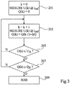
- the figure 3 illustrates, in block form, a non-limiting example of an embodiment of a method for determining the SOH of a cell of a battery, which may be implemented during a discharge phase of the cell. It will be noted that from the description which follows, those skilled in the art will be able to adapt the method of figure 3 to determine the SOH during a charging phase of the cell.
- the process of figure 3 can be triggered by the battery management device during a discharge phase of the cell, before the charge level of the cell reaches the value Q A.
- the process of figure 3 is triggered when the state of charge of the cell reaches a threshold in the range of 60% to 80% of SOC.
- step 203 after step 201, the index k pointing in the U and Q tables is incremented by 1, and the voltage across the cell is again measured under the current i ref .
- the measured voltage value is written in the field U (k) of the table U.
- the load variation ⁇ Q of the cell between the step of measuring the voltage U (k- 1) and the step of measuring the voltage U (k) is determined, for example by coulometric counting, or estimated from the time elapsed between the two measurements.
- the Q (k-1) + ⁇ Q value is written in the Q (k) field of the Q table.
- the management device checks whether the voltage U (k) measured in step 203 has crossed the voltage value U A of the characteristic point A of the cell. If, during step 205, the value U (k) is greater than the value U A , steps 203 and 205 are repeated.
- a step 207 is implemented during which the management device checks whether the load variation Q (k) of the cell since the beginning of the process has reached a threshold Q S. If, in step 205, the value Q (k) is below the threshold Q S , the steps 203, 205 and 207 are repeated. If, during step 207, the value Q (k) is greater than or equal to the value Q S , a step 209 for determining the SOH of the cell is implemented.
- the SOH can for example be determined from the values contained in the tables U and Q, according to one of the abovementioned methods, namely by calculating a magnitude representative of the slope, at the point of voltage U A , of the characteristic curve of the voltage of the cell under the current i ref as a function of the load variations of the cell, or by calculation of a magnitude representative of the average of the voltage of the cell under the current i ref in a range of cell charge levels greater than point A or lower than point A.
- the process for determining the SOH terminates.
- the battery management device can optionally store, in addition to the coordinates of the point A, the entirety of one or more of the characteristic voltage / charge curves of the cells at a reference current i ref , determined during a characterization phase of the cells.
- the management device can measure the voltage across the cell under the current i ref , and estimate the state of charge of the cell. cell from this measurement and memorized characteristic curves.
- the particular curve used to make a state of charge estimation of a cell can be selected taking into account the SOH of the cell.
- the coordinates of the point A, as well as the characteristic slopes of the voltage / charge curves at point A, and / or the characteristic averages of the voltage in a range of load levels excluding the point A can optionally be determined for several reference currents i ref distinct.
- the management device implements a phase for determining the SOH by a method of the aforementioned type, it can choose the reference current best suited to the use made of the battery during the determination phase. of SOH.
Landscapes
- Physics & Mathematics (AREA)
- General Physics & Mathematics (AREA)
- Secondary Cells (AREA)
- Charge And Discharge Circuits For Batteries Or The Like (AREA)
Claims (15)
- Ein Verfahren zum Bestimmen des Zustandes bzw. der Verfassung einer ersten Elementarzelle einer Batterie bzw. eines Akkus, das die folgenden Schritte aufweist:Messen der Spannung (U(k)) über die Zelle hinweg unter einem Referenzstrom (iref) zu einer Vielzahl von Zeiten in einer Phase einer Zellenladung oder -entladung zwischen ersten und zweiten Ladezustandspegeln; undDetektieren des Schneidens bzw. Übertretens, durch die Spannung (U(k)), eines vorbestimmten, spezifischen Wertes (UA), der einem vorbestimmten, spezifischen Ladungswert (QA) der Zelle entspricht, wobei die spezifischen Ladungswerte (QA) und Spannungswerte (UA) den Koordinaten eines Schnittpunktes (A) von wenigstens zwei Kurven (101 a, 101 b, 101 c) entsprechen, die für die Variation der Spannung (U(k)) gemäß der Ladung, die in der Zelle enthalten ist, repräsentativ sind, und zwar für unterschiedliche Verfassungen der Zelle.
- Verfahren nach Anspruch 1, das weiter Bestimmen und Speichern von Variationen der Zellenladung (ΔQ) zwischen den Spannungsmessungen aufweist.
- Verfahren nach Anspruch 2, wobei die Ladungsvariationen (ΔQ, Q(k)) durch ein Coulometer oder einen Stromintegrierer gemessen werden.
- Verfahren nach Anspruch 2, wobei die Ladungsvariationen (ΔQ, Q(k)) geschätzt werden, indem die Zeit berücksichtigt wird, die zwischen Spannungsmessungen verstrichen ist.
- Verfahren nach einem der Ansprüche 2 bis 4, das einen Schritt des Bestimmens der Steigung der Kurve aufweist, die für die Variation der Spannung (U(k)) gemäß der Ladungsvariation (ΔQ, Q(k)) der Zelle repräsentativ ist, und zwar an dem Schnittpunkt bzw. beim Übertreten des spezifischen Spannungswertes (UA).
- Verfahren nach einem der Ansprüche 2 bis 4, das einen Schritt des Berechnens des durchschnittlichen Wertes der Spannung (U(k)) zwischen ersten und zweiten Zellenladungspegeln aufweist, wobei die ersten und zweiten Ladungspegel beide höher sind als der spezifische Ladungswert (QA) oder beide niedriger sind als der spezifische Ladungswert (QA).
- Verfahren nach einem der Ansprüche 1 bis 6, das weiter, nach dem Detektieren des Schneidens bzw. Übertretens, durch die Spannung (U(k)), des vorbestimmen spezifischen Wertes (UA), einen Schritt einer vollen Wiederaufladung der Zelle und die Messung der Ladung, die in die Zelle während dieses Wiederaufladungsschrittes eingespeist wird, aufweist.
- Verfahren nach einem der Ansprüche 1 bis 7, wobei der spezifische Ladungswert (QA) in dem Bereich von 20% bis 60% der nominalen vollen Ladungskapazität der Zelle ist.
- Verfahren nach einem der Ansprüche 1 bis 8, wobei die Zelle eine Zelle vom Lithium-Ionen-Typ ist und wobei der spezifische Ladungswert (QA) in dem Bereich von 38% bis 42% der nominalen, vollen Ladungskapazität der Zelle ist.
- Verfahren nach Anspruch 9, wobei die Zelle eine Nennkapazität von 2,2Ah und eine Nennspannung 4,2V bei voller Ladung hat, und wobei der spezifische Spannungswert (QA) in dem Bereich von 3,5 V bis 3,6 V ist.
- Verfahren nach einem der Ansprüche 1 bis 10, das weiter eine vorherige Charakterisierungsphase aufweist, die Erfassen, für eine zweite Elementarzelle desselben Typs wie die erste Zelle, von wenigstens zwei charakteristischen Kurven (101 a, 101b, 101c) aufweist, die für die Variation der Spannung über die zweite Zelle hinweg gemäß der Ladung, die in der zweiten Zelle enthalten ist, repräsentativ ist, für wenigstens zwei unterschiedliche Zustände bzw. Verfassungen der zweite Zelle.
- Verfahren nach Anspruch 11, wobei die vorherige Charakterisierungsphase weiter einen Schritt des Bestimmens eines Schnittpunktes (A) der wenigstens zwei charakteristischen Kurven in dem Ladungsbereich von 20% bis 60% der nominalen Kapazität der Zelle aufweist.
- Ein System, das Folgendes aufweist:eine Batterie bzw. einen Akku, der eine Vielzahl von Elementarzellen aufweist; undeine Batteriemanagementeinrichtung,wobei die Managementeinrichtung in der Lage ist, den Zustand bzw. die Verfassung einer Elementarzelle durch das Verfahren eines der Ansprüche 1 bis 12 zu bestimmen.
- System nach Anspruch 13, wobei die Batterie bzw. der Akku eine Batterie bzw. ein Akku mit einer dynamisch rekonfigurierbaren Architektur ist, und wobei die Managementeinrichtung in der Lage ist, dynamisch Zellen der Batterie bzw. des Akkus zu trennen und wieder zu verbinden, so dass eine AC- bzw. Wechselstromspannung über die Batterie hinweg vorgesehen wird.
- System nach Anspruch 14, wobei der Referenzstrom (iref) Null ist und wobei die Schritte des Messens der Spannung (U(k)) über die erste Zelle hinweg während Perioden der Trennung der ersten Zelle durch die Managementeinrichtung zur Generierung einer AC-Spannung über die Batterie hinweg implementiert werden.
Applications Claiming Priority (1)
| Application Number | Priority Date | Filing Date | Title |
|---|---|---|---|
| FR1452182A FR3018608B1 (fr) | 2014-03-17 | 2014-03-17 | Procede d'estimation de l'etat de sante d'une cellule de batterie |
Publications (2)
| Publication Number | Publication Date |
|---|---|
| EP2944970A1 EP2944970A1 (de) | 2015-11-18 |
| EP2944970B1 true EP2944970B1 (de) | 2016-12-14 |
Family
ID=50624830
Family Applications (1)
| Application Number | Title | Priority Date | Filing Date |
|---|---|---|---|
| EP15158714.4A Active EP2944970B1 (de) | 2014-03-17 | 2015-03-11 | Verfahren zur Abschätzung des Gesundheitszustands einer Batteriezelle |
Country Status (5)
| Country | Link |
|---|---|
| US (1) | US9759776B2 (de) |
| EP (1) | EP2944970B1 (de) |
| JP (1) | JP6460860B2 (de) |
| CN (1) | CN104965176B (de) |
| FR (1) | FR3018608B1 (de) |
Families Citing this family (21)
| Publication number | Priority date | Publication date | Assignee | Title |
|---|---|---|---|---|
| FR3018607B1 (fr) * | 2014-03-17 | 2017-11-24 | Commissariat Energie Atomique | Procede d'estimation et de recalage de l'etat de charge d'une cellule de batterie |
| AU2016203834A1 (en) * | 2015-06-17 | 2017-01-12 | Gs Yuasa International Ltd. | State estimation device and state estimation method |
| US10006967B2 (en) * | 2015-10-16 | 2018-06-26 | Samsung Electronics Co., Ltd. | Battery management system for predicting life of a reconfigurable battery pack |
| FR3054669B1 (fr) * | 2016-07-29 | 2018-07-27 | Commissariat A L'energie Atomique Et Aux Energies Alternatives | Procede de determination de l'etat de sante des cellules d'une batterie |
| CN107121640A (zh) * | 2017-05-12 | 2017-09-01 | 四川力垦锂动力科技有限公司 | 电动汽车用锂电池soh统计系统 |
| CN107144794A (zh) * | 2017-05-12 | 2017-09-08 | 四川力垦锂动力科技有限公司 | 一种电动汽车用锂电池健康度统计方法 |
| CN107271906B (zh) * | 2017-05-31 | 2019-10-18 | 宁德时代新能源科技股份有限公司 | 电池包健康度估算方法和装置 |
| KR102695521B1 (ko) | 2018-09-20 | 2024-08-14 | 삼성전자주식회사 | 배터리 상태 추정 장치 및 방법 |
| FR3090116B1 (fr) * | 2018-12-12 | 2020-12-25 | Commissariat Energie Atomique | Procédé de détermination de l'état de santé des cellules d'une batterie |
| FR3090118B1 (fr) * | 2018-12-12 | 2020-12-25 | Commissariat Energie Atomique | Procédé de détermination de l'état de santé des cellules d'une batterie |
| FR3090114B1 (fr) | 2018-12-17 | 2020-12-25 | Electricite De France | Santé d’une batterie |
| EP3894876B1 (de) * | 2019-01-24 | 2022-12-14 | Siemens Aktiengesellschaft | Verfahren und system zur überwachung eines batteriezustands unter verwendung einer batterie |
| US11340300B2 (en) | 2019-04-05 | 2022-05-24 | Samsung Electronics Co., Ltd. | Battery service life management method and system |
| CN111934369B (zh) * | 2019-05-13 | 2022-09-06 | Oppo广东移动通信有限公司 | 充电方法及装置、设备、存储介质 |
| CN110133531B (zh) * | 2019-05-24 | 2020-08-21 | 上海钧正网络科技有限公司 | 一种电池监测方法、装置及电子设备 |
| CN110888064B (zh) * | 2019-12-20 | 2021-10-08 | 厦门金龙联合汽车工业有限公司 | 一种评估电池系统电芯容量分布区间的算法 |
| DE102020121098A1 (de) * | 2020-08-11 | 2022-02-17 | Lisa Dräxlmaier GmbH | Batteriemanagementsystem zum Klassifizieren eines Batteriemoduls |
| IT202100021923A1 (it) | 2021-08-16 | 2023-02-16 | Agenzia Naz Per Le Nuove Tecnologie Lenergia E Lo Sviluppo Economico Sostenibile Enea | Metodo per determinare lo stato di salute di almeno una batteria elettrica |
| FR3131386B1 (fr) | 2021-12-28 | 2024-10-04 | Commissariat Energie Atomique | Détermination de l’état de santé d’un accumulateur électrique par conversion |
| CN116338487B (zh) * | 2023-05-29 | 2023-10-20 | 宁德时代新能源科技股份有限公司 | 电芯检测方法、装置、电子设备及存储介质 |
| CN117907831B (zh) * | 2024-03-01 | 2025-10-31 | 安徽得壹能源科技有限公司 | 一种锂离子电池稳定放电能力评估方法及系统 |
Family Cites Families (21)
| Publication number | Priority date | Publication date | Assignee | Title |
|---|---|---|---|---|
| FR1452182A (fr) | 1964-09-08 | 1966-02-25 | Siemens Ag | Installation pour poste d'abonné télégraphique dans des réseaux à sélection automatique |
| JP3395694B2 (ja) * | 1999-03-09 | 2003-04-14 | 日産自動車株式会社 | 二次電池の電池容量劣化算出方法 |
| ATE489757T1 (de) * | 2001-05-29 | 2010-12-15 | Canon Kk | Verfahren, vorrichtung und programm zur erfassung von internen informationen einer wiederaufladbaren batterie und diese erfassungsvorrichtung enthaltende vorrichtung |
| JP4032934B2 (ja) | 2002-11-15 | 2008-01-16 | ソニー株式会社 | 電池容量算出方法、電池容量算出装置、及び電池容量算出プログラム |
| US7714531B2 (en) * | 2004-03-18 | 2010-05-11 | Panasonic Corporation | Power system and management method thereof |
| DE102005052448A1 (de) * | 2004-11-03 | 2006-07-20 | Continental Teves Ag & Co. Ohg | Verfahren zum Ermitteln der Funktionsfähigkeit einer Speicherbatterie |
| JP5261828B2 (ja) * | 2009-05-12 | 2013-08-14 | 本田技研工業株式会社 | 電池状態推定装置 |
| US8791669B2 (en) * | 2010-06-24 | 2014-07-29 | Qnovo Inc. | Method and circuitry to calculate the state of charge of a battery/cell |
| GB2481119B (en) | 2010-06-09 | 2015-11-04 | Chervon Hk Ltd | Battery capacity display for a power tool |
| US9285433B2 (en) * | 2010-06-24 | 2016-03-15 | Toyota Jidosha Kabushiki Kaisha | Battery management system, battery management apparatus, method of reusing battery, and information communication terminal apparatus |
| US8450978B2 (en) * | 2010-08-27 | 2013-05-28 | Texas Instruments Incorporated | Monitoring a rechargeable battery with multiple parameter update rates |
| FR2972304A1 (fr) | 2011-03-02 | 2012-09-07 | Commissariat Energie Atomique | Batterie avec gestion individuelle des cellules |
| FR2972306A1 (fr) | 2011-03-02 | 2012-09-07 | Commissariat Energie Atomique | Batterie avec gestion individuelle des cellules |
| JP2012242135A (ja) | 2011-05-16 | 2012-12-10 | Sanyo Electric Co Ltd | 残容量算出方法、パック電池の出荷前調整方法、残容量算出装置及びパック電池 |
| CN202119883U (zh) * | 2011-06-20 | 2012-01-18 | 江南大学 | 车用蓄电池检测系统 |
| JP5404712B2 (ja) * | 2011-08-10 | 2014-02-05 | 三菱電機株式会社 | 充電装置、車載用充電装置、車載用充電装置における充電方法 |
| JP5737138B2 (ja) * | 2011-11-01 | 2015-06-17 | トヨタ自動車株式会社 | 電池の制御装置及び電池の制御方法 |
| CN102540096B (zh) * | 2012-01-17 | 2014-07-23 | 浙江大学 | 一种用于磷酸铁锂动力电池剩余容量估算自修正的方法 |
| US9461490B2 (en) | 2013-03-13 | 2016-10-04 | GM Global Technology Operations LLC | Method and apparatus for evaluating a rechargeable battery |
| US20140306712A1 (en) | 2013-04-12 | 2014-10-16 | Broadcom Corporation | Tracking aging effect on battery impedance and tracking battery state of health |
| FR3018607B1 (fr) * | 2014-03-17 | 2017-11-24 | Commissariat Energie Atomique | Procede d'estimation et de recalage de l'etat de charge d'une cellule de batterie |
-
2014
- 2014-03-17 FR FR1452182A patent/FR3018608B1/fr active Active
-
2015
- 2015-03-11 EP EP15158714.4A patent/EP2944970B1/de active Active
- 2015-03-16 US US14/658,581 patent/US9759776B2/en active Active
- 2015-03-17 JP JP2015053840A patent/JP6460860B2/ja not_active Expired - Fee Related
- 2015-03-17 CN CN201510117102.6A patent/CN104965176B/zh not_active Expired - Fee Related
Non-Patent Citations (1)
| Title |
|---|
| None * |
Also Published As
| Publication number | Publication date |
|---|---|
| JP6460860B2 (ja) | 2019-01-30 |
| EP2944970A1 (de) | 2015-11-18 |
| FR3018608B1 (fr) | 2017-11-24 |
| CN104965176A (zh) | 2015-10-07 |
| JP2015175854A (ja) | 2015-10-05 |
| US9759776B2 (en) | 2017-09-12 |
| US20150260795A1 (en) | 2015-09-17 |
| FR3018608A1 (fr) | 2015-09-18 |
| CN104965176B (zh) | 2020-01-21 |
Similar Documents
| Publication | Publication Date | Title |
|---|---|---|
| EP2944970B1 (de) | Verfahren zur Abschätzung des Gesundheitszustands einer Batteriezelle | |
| EP3028054B1 (de) | Einschätzung des zersetzungszustands einer strombatterie | |
| EP3324197B1 (de) | Verfahren zur bestimmung des zustands einer batteriezelle | |
| EP2707935B1 (de) | Verfahren zur batterieverwaltung und diagnose | |
| EP3079940B1 (de) | Beurteilung der energiemenge bei einer kraftfahrzeugbatterie | |
| EP3276364B1 (de) | Verfahren zur bestimmung des gesundheitszustands der zellen einer batterie | |
| EP3258282A1 (de) | Verfahren und vorrichtung zur bewertung eines gesundheitszustandsindikators einer zelle einer lithium-batterie | |
| FR2963109A1 (fr) | Procede de determination d'un parametre d'au moins un accumulateur d'une batterie | |
| WO2015086753A1 (fr) | Procede d'estimation de l'etat de sante d'une batterie | |
| EP2924454B1 (de) | Verfahren zur Abschätzung und Neueinstellung des Ladezustands einer Batteriezelle | |
| WO2010049148A1 (fr) | Procede de determination de l'etat de charge d'une batterie en phase de charge ou de decharge | |
| EP3667345B1 (de) | Verfahren zur bestimmung des gesundheitszustands der zellen einer batterie | |
| EP3671243B1 (de) | Verfahren zur bestimmung des gesundheitszustands der zellen einer batterie | |
| FR3041765A1 (fr) | Procede d'estimation d'un indicateur d'etat de sante d'une batterie lithium et dispositif d'estimation associe | |
| EP4081817A1 (de) | Verfahren zum identifizieren des beginns der beschleunigung der verschlechterung des gesundheitszustands eines packs von wiederaufladbaren batterien | |
| EP2880708B1 (de) | Verfahren zur verwaltung und diagnose einer batterie | |
| EP3894877B1 (de) | Verfahren zur bestimmung des gesundheitszustands der zellen einer batterie | |
| WO2017108536A1 (fr) | Procede d'evaluation de l'etat de charge d'une batterie | |
| EP3999864B1 (de) | Verfahren zur bestimmung des gesundheitszustands der zellen einer batterie | |
| FR3098921A1 (fr) | Estimation du SoH d’un élément électrochimique |
Legal Events
| Date | Code | Title | Description |
|---|---|---|---|
| PUAI | Public reference made under article 153(3) epc to a published international application that has entered the european phase |
Free format text: ORIGINAL CODE: 0009012 |
|
| AK | Designated contracting states |
Kind code of ref document: A1 Designated state(s): AL AT BE BG CH CY CZ DE DK EE ES FI FR GB GR HR HU IE IS IT LI LT LU LV MC MK MT NL NO PL PT RO RS SE SI SK SM TR |
|
| AX | Request for extension of the european patent |
Extension state: BA ME |
|
| 17P | Request for examination filed |
Effective date: 20160428 |
|
| RBV | Designated contracting states (corrected) |
Designated state(s): AL AT BE BG CH CY CZ DE DK EE ES FI FR GB GR HR HU IE IS IT LI LT LU LV MC MK MT NL NO PL PT RO RS SE SI SK SM TR |
|
| GRAP | Despatch of communication of intention to grant a patent |
Free format text: ORIGINAL CODE: EPIDOSNIGR1 |
|
| RIC1 | Information provided on ipc code assigned before grant |
Ipc: G01R 31/36 20060101AFI20160729BHEP |
|
| INTG | Intention to grant announced |
Effective date: 20160906 |
|
| STAA | Information on the status of an ep patent application or granted ep patent |
Free format text: STATUS: GRANT OF PATENT IS INTENDED |
|
| GRAS | Grant fee paid |
Free format text: ORIGINAL CODE: EPIDOSNIGR3 |
|
| GRAA | (expected) grant |
Free format text: ORIGINAL CODE: 0009210 |
|
| STAA | Information on the status of an ep patent application or granted ep patent |
Free format text: STATUS: THE PATENT HAS BEEN GRANTED |
|
| AK | Designated contracting states |
Kind code of ref document: B1 Designated state(s): AL AT BE BG CH CY CZ DE DK EE ES FI FR GB GR HR HU IE IS IT LI LT LU LV MC MK MT NL NO PL PT RO RS SE SI SK SM TR |
|
| REG | Reference to a national code |
Ref country code: GB Ref legal event code: FG4D Free format text: NOT ENGLISH |
|
| REG | Reference to a national code |
Ref country code: CH Ref legal event code: EP |
|
| REG | Reference to a national code |
Ref country code: IE Ref legal event code: FG4D Free format text: LANGUAGE OF EP DOCUMENT: FRENCH |
|
| REG | Reference to a national code |
Ref country code: AT Ref legal event code: REF Ref document number: 854076 Country of ref document: AT Kind code of ref document: T Effective date: 20170115 |
|
| REG | Reference to a national code |
Ref country code: DE Ref legal event code: R096 Ref document number: 602015000966 Country of ref document: DE |
|
| PG25 | Lapsed in a contracting state [announced via postgrant information from national office to epo] |
Ref country code: LV Free format text: LAPSE BECAUSE OF FAILURE TO SUBMIT A TRANSLATION OF THE DESCRIPTION OR TO PAY THE FEE WITHIN THE PRESCRIBED TIME-LIMIT Effective date: 20161214 |
|
| REG | Reference to a national code |
Ref country code: FR Ref legal event code: PLFP Year of fee payment: 3 |
|
| REG | Reference to a national code |
Ref country code: LT Ref legal event code: MG4D |
|
| REG | Reference to a national code |
Ref country code: NL Ref legal event code: MP Effective date: 20161214 |
|
| PG25 | Lapsed in a contracting state [announced via postgrant information from national office to epo] |
Ref country code: NO Free format text: LAPSE BECAUSE OF FAILURE TO SUBMIT A TRANSLATION OF THE DESCRIPTION OR TO PAY THE FEE WITHIN THE PRESCRIBED TIME-LIMIT Effective date: 20170314 Ref country code: SE Free format text: LAPSE BECAUSE OF FAILURE TO SUBMIT A TRANSLATION OF THE DESCRIPTION OR TO PAY THE FEE WITHIN THE PRESCRIBED TIME-LIMIT Effective date: 20161214 Ref country code: LT Free format text: LAPSE BECAUSE OF FAILURE TO SUBMIT A TRANSLATION OF THE DESCRIPTION OR TO PAY THE FEE WITHIN THE PRESCRIBED TIME-LIMIT Effective date: 20161214 Ref country code: GR Free format text: LAPSE BECAUSE OF FAILURE TO SUBMIT A TRANSLATION OF THE DESCRIPTION OR TO PAY THE FEE WITHIN THE PRESCRIBED TIME-LIMIT Effective date: 20170315 |
|
| REG | Reference to a national code |
Ref country code: AT Ref legal event code: MK05 Ref document number: 854076 Country of ref document: AT Kind code of ref document: T Effective date: 20161214 |
|
| PG25 | Lapsed in a contracting state [announced via postgrant information from national office to epo] |
Ref country code: HR Free format text: LAPSE BECAUSE OF FAILURE TO SUBMIT A TRANSLATION OF THE DESCRIPTION OR TO PAY THE FEE WITHIN THE PRESCRIBED TIME-LIMIT Effective date: 20161214 Ref country code: FI Free format text: LAPSE BECAUSE OF FAILURE TO SUBMIT A TRANSLATION OF THE DESCRIPTION OR TO PAY THE FEE WITHIN THE PRESCRIBED TIME-LIMIT Effective date: 20161214 Ref country code: RS Free format text: LAPSE BECAUSE OF FAILURE TO SUBMIT A TRANSLATION OF THE DESCRIPTION OR TO PAY THE FEE WITHIN THE PRESCRIBED TIME-LIMIT Effective date: 20161214 |
|
| PG25 | Lapsed in a contracting state [announced via postgrant information from national office to epo] |
Ref country code: NL Free format text: LAPSE BECAUSE OF FAILURE TO SUBMIT A TRANSLATION OF THE DESCRIPTION OR TO PAY THE FEE WITHIN THE PRESCRIBED TIME-LIMIT Effective date: 20161214 |
|
| PG25 | Lapsed in a contracting state [announced via postgrant information from national office to epo] |
Ref country code: IS Free format text: LAPSE BECAUSE OF FAILURE TO SUBMIT A TRANSLATION OF THE DESCRIPTION OR TO PAY THE FEE WITHIN THE PRESCRIBED TIME-LIMIT Effective date: 20170414 Ref country code: SK Free format text: LAPSE BECAUSE OF FAILURE TO SUBMIT A TRANSLATION OF THE DESCRIPTION OR TO PAY THE FEE WITHIN THE PRESCRIBED TIME-LIMIT Effective date: 20161214 Ref country code: CZ Free format text: LAPSE BECAUSE OF FAILURE TO SUBMIT A TRANSLATION OF THE DESCRIPTION OR TO PAY THE FEE WITHIN THE PRESCRIBED TIME-LIMIT Effective date: 20161214 Ref country code: EE Free format text: LAPSE BECAUSE OF FAILURE TO SUBMIT A TRANSLATION OF THE DESCRIPTION OR TO PAY THE FEE WITHIN THE PRESCRIBED TIME-LIMIT Effective date: 20161214 Ref country code: RO Free format text: LAPSE BECAUSE OF FAILURE TO SUBMIT A TRANSLATION OF THE DESCRIPTION OR TO PAY THE FEE WITHIN THE PRESCRIBED TIME-LIMIT Effective date: 20161214 |
|
| PG25 | Lapsed in a contracting state [announced via postgrant information from national office to epo] |
Ref country code: BG Free format text: LAPSE BECAUSE OF FAILURE TO SUBMIT A TRANSLATION OF THE DESCRIPTION OR TO PAY THE FEE WITHIN THE PRESCRIBED TIME-LIMIT Effective date: 20170314 Ref country code: PT Free format text: LAPSE BECAUSE OF FAILURE TO SUBMIT A TRANSLATION OF THE DESCRIPTION OR TO PAY THE FEE WITHIN THE PRESCRIBED TIME-LIMIT Effective date: 20170414 Ref country code: AT Free format text: LAPSE BECAUSE OF FAILURE TO SUBMIT A TRANSLATION OF THE DESCRIPTION OR TO PAY THE FEE WITHIN THE PRESCRIBED TIME-LIMIT Effective date: 20161214 Ref country code: SM Free format text: LAPSE BECAUSE OF FAILURE TO SUBMIT A TRANSLATION OF THE DESCRIPTION OR TO PAY THE FEE WITHIN THE PRESCRIBED TIME-LIMIT Effective date: 20161214 Ref country code: ES Free format text: LAPSE BECAUSE OF FAILURE TO SUBMIT A TRANSLATION OF THE DESCRIPTION OR TO PAY THE FEE WITHIN THE PRESCRIBED TIME-LIMIT Effective date: 20161214 Ref country code: PL Free format text: LAPSE BECAUSE OF FAILURE TO SUBMIT A TRANSLATION OF THE DESCRIPTION OR TO PAY THE FEE WITHIN THE PRESCRIBED TIME-LIMIT Effective date: 20161214 Ref country code: IT Free format text: LAPSE BECAUSE OF FAILURE TO SUBMIT A TRANSLATION OF THE DESCRIPTION OR TO PAY THE FEE WITHIN THE PRESCRIBED TIME-LIMIT Effective date: 20161214 |
|
| REG | Reference to a national code |
Ref country code: DE Ref legal event code: R097 Ref document number: 602015000966 Country of ref document: DE |
|
| PLBE | No opposition filed within time limit |
Free format text: ORIGINAL CODE: 0009261 |
|
| STAA | Information on the status of an ep patent application or granted ep patent |
Free format text: STATUS: NO OPPOSITION FILED WITHIN TIME LIMIT |
|
| 26N | No opposition filed |
Effective date: 20170915 |
|
| PG25 | Lapsed in a contracting state [announced via postgrant information from national office to epo] |
Ref country code: MC Free format text: LAPSE BECAUSE OF FAILURE TO SUBMIT A TRANSLATION OF THE DESCRIPTION OR TO PAY THE FEE WITHIN THE PRESCRIBED TIME-LIMIT Effective date: 20161214 Ref country code: DK Free format text: LAPSE BECAUSE OF FAILURE TO SUBMIT A TRANSLATION OF THE DESCRIPTION OR TO PAY THE FEE WITHIN THE PRESCRIBED TIME-LIMIT Effective date: 20161214 |
|
| REG | Reference to a national code |
Ref country code: IE Ref legal event code: MM4A |
|
| PG25 | Lapsed in a contracting state [announced via postgrant information from national office to epo] |
Ref country code: LU Free format text: LAPSE BECAUSE OF NON-PAYMENT OF DUE FEES Effective date: 20170311 |
|
| PG25 | Lapsed in a contracting state [announced via postgrant information from national office to epo] |
Ref country code: IE Free format text: LAPSE BECAUSE OF NON-PAYMENT OF DUE FEES Effective date: 20170311 Ref country code: SI Free format text: LAPSE BECAUSE OF FAILURE TO SUBMIT A TRANSLATION OF THE DESCRIPTION OR TO PAY THE FEE WITHIN THE PRESCRIBED TIME-LIMIT Effective date: 20161214 |
|
| REG | Reference to a national code |
Ref country code: BE Ref legal event code: MM Effective date: 20170331 |
|
| REG | Reference to a national code |
Ref country code: FR Ref legal event code: PLFP Year of fee payment: 4 |
|
| PG25 | Lapsed in a contracting state [announced via postgrant information from national office to epo] |
Ref country code: BE Free format text: LAPSE BECAUSE OF NON-PAYMENT OF DUE FEES Effective date: 20170331 |
|
| PG25 | Lapsed in a contracting state [announced via postgrant information from national office to epo] |
Ref country code: MT Free format text: LAPSE BECAUSE OF FAILURE TO SUBMIT A TRANSLATION OF THE DESCRIPTION OR TO PAY THE FEE WITHIN THE PRESCRIBED TIME-LIMIT Effective date: 20161214 |
|
| REG | Reference to a national code |
Ref country code: CH Ref legal event code: PL |
|
| PG25 | Lapsed in a contracting state [announced via postgrant information from national office to epo] |
Ref country code: LI Free format text: LAPSE BECAUSE OF NON-PAYMENT OF DUE FEES Effective date: 20180331 Ref country code: CH Free format text: LAPSE BECAUSE OF NON-PAYMENT OF DUE FEES Effective date: 20180331 |
|
| PG25 | Lapsed in a contracting state [announced via postgrant information from national office to epo] |
Ref country code: HU Free format text: LAPSE BECAUSE OF FAILURE TO SUBMIT A TRANSLATION OF THE DESCRIPTION OR TO PAY THE FEE WITHIN THE PRESCRIBED TIME-LIMIT; INVALID AB INITIO Effective date: 20150311 |
|
| PG25 | Lapsed in a contracting state [announced via postgrant information from national office to epo] |
Ref country code: CY Free format text: LAPSE BECAUSE OF FAILURE TO SUBMIT A TRANSLATION OF THE DESCRIPTION OR TO PAY THE FEE WITHIN THE PRESCRIBED TIME-LIMIT Effective date: 20161214 |
|
| PG25 | Lapsed in a contracting state [announced via postgrant information from national office to epo] |
Ref country code: MK Free format text: LAPSE BECAUSE OF FAILURE TO SUBMIT A TRANSLATION OF THE DESCRIPTION OR TO PAY THE FEE WITHIN THE PRESCRIBED TIME-LIMIT Effective date: 20161214 |
|
| PG25 | Lapsed in a contracting state [announced via postgrant information from national office to epo] |
Ref country code: TR Free format text: LAPSE BECAUSE OF FAILURE TO SUBMIT A TRANSLATION OF THE DESCRIPTION OR TO PAY THE FEE WITHIN THE PRESCRIBED TIME-LIMIT Effective date: 20161214 |
|
| PG25 | Lapsed in a contracting state [announced via postgrant information from national office to epo] |
Ref country code: AL Free format text: LAPSE BECAUSE OF FAILURE TO SUBMIT A TRANSLATION OF THE DESCRIPTION OR TO PAY THE FEE WITHIN THE PRESCRIBED TIME-LIMIT Effective date: 20161214 |
|
| P01 | Opt-out of the competence of the unified patent court (upc) registered |
Effective date: 20230517 |
|
| PGFP | Annual fee paid to national office [announced via postgrant information from national office to epo] |
Ref country code: DE Payment date: 20250319 Year of fee payment: 11 |
|
| PGFP | Annual fee paid to national office [announced via postgrant information from national office to epo] |
Ref country code: GB Payment date: 20250324 Year of fee payment: 11 |
|
| PGFP | Annual fee paid to national office [announced via postgrant information from national office to epo] |
Ref country code: FR Payment date: 20260324 Year of fee payment: 12 |