EP2945097A1 - Procédé de reconnaissance d'empreintes digitales et dispositif électronique pour la mise en oeuvre de celui-ci - Google Patents
Procédé de reconnaissance d'empreintes digitales et dispositif électronique pour la mise en oeuvre de celui-ci Download PDFInfo
- Publication number
- EP2945097A1 EP2945097A1 EP15167174.0A EP15167174A EP2945097A1 EP 2945097 A1 EP2945097 A1 EP 2945097A1 EP 15167174 A EP15167174 A EP 15167174A EP 2945097 A1 EP2945097 A1 EP 2945097A1
- Authority
- EP
- European Patent Office
- Prior art keywords
- fingerprint
- electronic device
- fingerprint sensor
- unrecognizable
- sensor
- Prior art date
- Legal status (The legal status is an assumption and is not a legal conclusion. Google has not performed a legal analysis and makes no representation as to the accuracy of the status listed.)
- Granted
Links
Images





Classifications
-
- G—PHYSICS
- G06—COMPUTING OR CALCULATING; COUNTING
- G06V—IMAGE OR VIDEO RECOGNITION OR UNDERSTANDING
- G06V40/00—Recognition of biometric, human-related or animal-related patterns in image or video data
- G06V40/10—Human or animal bodies, e.g. vehicle occupants or pedestrians; Body parts, e.g. hands
- G06V40/12—Fingerprints or palmprints
- G06V40/1335—Combining adjacent partial images (e.g. slices) to create a composite input or reference pattern; Tracking a sweeping finger movement
-
- G—PHYSICS
- G06—COMPUTING OR CALCULATING; COUNTING
- G06V—IMAGE OR VIDEO RECOGNITION OR UNDERSTANDING
- G06V40/00—Recognition of biometric, human-related or animal-related patterns in image or video data
- G06V40/10—Human or animal bodies, e.g. vehicle occupants or pedestrians; Body parts, e.g. hands
- G06V40/12—Fingerprints or palmprints
- G06V40/13—Sensors therefor
-
- G—PHYSICS
- G06—COMPUTING OR CALCULATING; COUNTING
- G06F—ELECTRIC DIGITAL DATA PROCESSING
- G06F1/00—Details not covered by groups G06F3/00 - G06F13/00 and G06F21/00
- G06F1/16—Constructional details or arrangements
- G06F1/1613—Constructional details or arrangements for portable computers
- G06F1/1633—Constructional details or arrangements of portable computers not specific to the type of enclosures covered by groups G06F1/1615 - G06F1/1626
- G06F1/1637—Details related to the display arrangement, including those related to the mounting of the display in the housing
- G06F1/1652—Details related to the display arrangement, including those related to the mounting of the display in the housing the display being flexible, e.g. mimicking a sheet of paper, or rollable
-
- G—PHYSICS
- G06—COMPUTING OR CALCULATING; COUNTING
- G06F—ELECTRIC DIGITAL DATA PROCESSING
- G06F21/00—Security arrangements for protecting computers, components thereof, programs or data against unauthorised activity
- G06F21/30—Authentication, i.e. establishing the identity or authorisation of security principals
- G06F21/31—User authentication
- G06F21/32—User authentication using biometric data, e.g. fingerprints, iris scans or voiceprints
-
- G—PHYSICS
- G06—COMPUTING OR CALCULATING; COUNTING
- G06F—ELECTRIC DIGITAL DATA PROCESSING
- G06F3/00—Input arrangements for transferring data to be processed into a form capable of being handled by the computer; Output arrangements for transferring data from processing unit to output unit, e.g. interface arrangements
- G06F3/01—Input arrangements or combined input and output arrangements for interaction between user and computer
- G06F3/03—Arrangements for converting the position or the displacement of a member into a coded form
- G06F3/041—Digitisers, e.g. for touch screens or touch pads, characterised by the transducing means
-
- G—PHYSICS
- G06—COMPUTING OR CALCULATING; COUNTING
- G06F—ELECTRIC DIGITAL DATA PROCESSING
- G06F3/00—Input arrangements for transferring data to be processed into a form capable of being handled by the computer; Output arrangements for transferring data from processing unit to output unit, e.g. interface arrangements
- G06F3/01—Input arrangements or combined input and output arrangements for interaction between user and computer
- G06F3/03—Arrangements for converting the position or the displacement of a member into a coded form
- G06F3/041—Digitisers, e.g. for touch screens or touch pads, characterised by the transducing means
- G06F3/0412—Digitisers structurally integrated in a display
-
- G—PHYSICS
- G06—COMPUTING OR CALCULATING; COUNTING
- G06V—IMAGE OR VIDEO RECOGNITION OR UNDERSTANDING
- G06V40/00—Recognition of biometric, human-related or animal-related patterns in image or video data
- G06V40/10—Human or animal bodies, e.g. vehicle occupants or pedestrians; Body parts, e.g. hands
- G06V40/12—Fingerprints or palmprints
- G06V40/13—Sensors therefor
- G06V40/1306—Sensors therefor non-optical, e.g. ultrasonic or capacitive sensing
-
- G—PHYSICS
- G06—COMPUTING OR CALCULATING; COUNTING
- G06V—IMAGE OR VIDEO RECOGNITION OR UNDERSTANDING
- G06V40/00—Recognition of biometric, human-related or animal-related patterns in image or video data
- G06V40/10—Human or animal bodies, e.g. vehicle occupants or pedestrians; Body parts, e.g. hands
- G06V40/12—Fingerprints or palmprints
- G06V40/1347—Preprocessing; Feature extraction
- G06V40/1353—Extracting features related to minutiae or pores
-
- G—PHYSICS
- G06—COMPUTING OR CALCULATING; COUNTING
- G06V—IMAGE OR VIDEO RECOGNITION OR UNDERSTANDING
- G06V40/00—Recognition of biometric, human-related or animal-related patterns in image or video data
- G06V40/10—Human or animal bodies, e.g. vehicle occupants or pedestrians; Body parts, e.g. hands
- G06V40/12—Fingerprints or palmprints
- G06V40/1347—Preprocessing; Feature extraction
- G06V40/1359—Extracting features related to ridge properties; Determining the fingerprint type, e.g. whorl or loop
-
- G—PHYSICS
- G06—COMPUTING OR CALCULATING; COUNTING
- G06V—IMAGE OR VIDEO RECOGNITION OR UNDERSTANDING
- G06V40/00—Recognition of biometric, human-related or animal-related patterns in image or video data
- G06V40/10—Human or animal bodies, e.g. vehicle occupants or pedestrians; Body parts, e.g. hands
- G06V40/12—Fingerprints or palmprints
- G06V40/1365—Matching; Classification
- G06V40/1371—Matching features related to minutiae or pores
-
- G—PHYSICS
- G06—COMPUTING OR CALCULATING; COUNTING
- G06V—IMAGE OR VIDEO RECOGNITION OR UNDERSTANDING
- G06V40/00—Recognition of biometric, human-related or animal-related patterns in image or video data
- G06V40/10—Human or animal bodies, e.g. vehicle occupants or pedestrians; Body parts, e.g. hands
- G06V40/12—Fingerprints or palmprints
- G06V40/1365—Matching; Classification
- G06V40/1376—Matching features related to ridge properties or fingerprint texture
-
- G—PHYSICS
- G06—COMPUTING OR CALCULATING; COUNTING
- G06F—ELECTRIC DIGITAL DATA PROCESSING
- G06F2203/00—Indexing scheme relating to G06F3/00 - G06F3/048
- G06F2203/041—Indexing scheme relating to G06F3/041 - G06F3/045
- G06F2203/04102—Flexible digitiser, i.e. constructional details for allowing the whole digitising part of a device to be flexed or rolled like a sheet of paper
-
- G—PHYSICS
- G06—COMPUTING OR CALCULATING; COUNTING
- G06F—ELECTRIC DIGITAL DATA PROCESSING
- G06F2203/00—Indexing scheme relating to G06F3/00 - G06F3/048
- G06F2203/041—Indexing scheme relating to G06F3/041 - G06F3/045
- G06F2203/04104—Multi-touch detection in digitiser, i.e. details about the simultaneous detection of a plurality of touching locations, e.g. multiple fingers or pen and finger
-
- G—PHYSICS
- G06—COMPUTING OR CALCULATING; COUNTING
- G06F—ELECTRIC DIGITAL DATA PROCESSING
- G06F2203/00—Indexing scheme relating to G06F3/00 - G06F3/048
- G06F2203/041—Indexing scheme relating to G06F3/041 - G06F3/045
- G06F2203/04112—Electrode mesh in capacitive digitiser: electrode for touch sensing is formed of a mesh of very fine, normally metallic, interconnected lines that are almost invisible to see. This provides a quite large but transparent electrode surface, without need for ITO or similar transparent conductive material
-
- G—PHYSICS
- G06—COMPUTING OR CALCULATING; COUNTING
- G06F—ELECTRIC DIGITAL DATA PROCESSING
- G06F3/00—Input arrangements for transferring data to be processed into a form capable of being handled by the computer; Output arrangements for transferring data from processing unit to output unit, e.g. interface arrangements
- G06F3/01—Input arrangements or combined input and output arrangements for interaction between user and computer
- G06F3/03—Arrangements for converting the position or the displacement of a member into a coded form
- G06F3/041—Digitisers, e.g. for touch screens or touch pads, characterised by the transducing means
- G06F3/044—Digitisers, e.g. for touch screens or touch pads, characterised by the transducing means by capacitive means
-
- G—PHYSICS
- G06—COMPUTING OR CALCULATING; COUNTING
- G06V—IMAGE OR VIDEO RECOGNITION OR UNDERSTANDING
- G06V2201/00—Indexing scheme relating to image or video recognition or understanding
- G06V2201/03—Recognition of patterns in medical or anatomical images
-
- G—PHYSICS
- G06—COMPUTING OR CALCULATING; COUNTING
- G06V—IMAGE OR VIDEO RECOGNITION OR UNDERSTANDING
- G06V40/00—Recognition of biometric, human-related or animal-related patterns in image or video data
- G06V40/10—Human or animal bodies, e.g. vehicle occupants or pedestrians; Body parts, e.g. hands
- G06V40/12—Fingerprints or palmprints
- G06V40/1347—Preprocessing; Feature extraction
Definitions
- the present disclosure relates to a fingerprint recognition method and electronic device performing thereof.
- a fingerprint sensor may be equipped at a front side or a backside of a portable terminal, or provided in a form of key or button which includes the fingerprint sensor. Furthermore, it is possible to provide the fingerprint sensor in a form of a display panel.
- an aspect of the present disclosure is to provide a fingerprint recognition sensor and an electronic device performing thereof.
- Technical subjects according to various embodiments of the present disclosure may not be restrictive to the aforementioned and may be present in other configurations.
- a fingerprint recognition method includes obtaining a fingerprint-unrecognizable position from a sensing area of a fingerprint sensor, obtaining a distance to the fingerprint from the fingerprint-unrecognizable position on the sensing area, and adjusting, based on the distance, a sensing operation of the fingerprint sensor.
- an electronic device includes a fingerprint sensor configured to perform a fingerprint sensing according to a control signal of a processor, and the processor configured to obtain a fingerprint-unrecognizable position from a sensing area of the fingerprint sensor, to obtain, based on the fingerprint-unrecognizable position, a distance to a fingerprint from the fingerprint-unrecognizable position, and to control, based on the distance, the fingerprint sensor by adjusting a sensing operation of the fingerprint sensor.
- FIGS. 1 through 17 discussed below, and the various embodiments used to describe the principles of the present disclosure in this patent document are by way of illustration only and should not be construed in any way that would limit the scope of the disclosure. Those skilled in the art will understand that the principles of the present disclosure may be implemented in any suitably arranged communications system.
- the terms used to describe various embodiments are exemplary. It should be understood that these are provided to merely aid the understanding of the description, and that their use and definitions in no way limit the scope of the present disclosure. Terms first, second, and the like are used to differentiate between objects having the same terminology and are in no way intended to represent a chronological order, unless where explicitly stated otherwise.
- a set is defined as a non-empty set including at least one element.
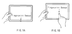
- FIGS. 1A and 1B are diagrams illustrating an electronic device capable of being equipped with a fingerprint sensor according to various embodiments of the present disclosure.
- a fingerprint sensor is illustrated, where the fingerprint sensor may be provided in a form that is equipped in a key or button, such as a home key.
- a fingerprint sensor is illustrated, where the fingerprint sensor may be provided in a form that is equipped in a display panel or in a touch panel, such as a unitary body of a display.
- a fingerprint sensor may be also equipped, in addition to the aforementioned positional features, in a front, side, or a back part of an electronic device.
- FIGS. 2A, 2B, 2C, 2D and 2E are diagrams illustrating circumstances where fingerprint sensors including curves recognize fingerprints according to various embodiments of the present disclosure. These curves may comprise a curved sensing area and may include all of various uneven types as well as slope, curve, asymmetrical, and the like.
- FIGS. 2A to 2C an operation of inputting a fingerprint into a curved sensing area by a user is illustrated.
- a terminal has a flexible display
- various areas of the flexible display may be used for the sensing area.
- a fingerprint sensor may perform fingerprint recognition if it detects an object (e.g., a human finger) through a sensing area.
- the sensing area may be an area from which a fingerprint sensor obtains a fingerprint input.
- FIGS. 2A to 2C A user may place their fingerprint on a fingerprint sensor, as shown in FIGS. 2A to 2C , to detect a fingerprint.
- a fingerprint sensor as shown in FIGS. 2A to 2C .
- the features shown FIGS. 2A to 2C are exemplarily shown without restriction to various embodiments of the present disclosure. For descriptive convenience, the curved type shown in FIG. 2A will be primarily described hereinafter.
- FIG. 2D an operation of recognizing a fingerprint through a curved sensing area 20 is illustrated.
- the sensing area 20 may be placed on a curved area of a terminal.
- a user may position a fingerprint 10 on the sensing area 20 to perform fingerprint recognition.
- the curve of the sensing area 20 may cause an irregularity of distances between the fingerprint 10 and the sensing area 20.
- the fingerprint sensor may have difficulty in recognizing an image from a part of the fingerprint 10. For example, if an obtained fingerprint image is distorted or indistinct, the fingerprint sensor may not recognize the fingerprint 10. As the distance between the fingerprint 10 and the sensing area 20 becomes larger and, in the curved area as shown in FIG. 2D , as the fingerprint 10 moves distant from the center of the curved area toward both ends thereof, an obtained fingerprint image may be distorted or indistinct.
- FIG. 2E an area 22 where a fingerprint image is distorted or indistinct due to a curve of the sensing area 20 is illustrated.
- a fingerprint 10 recognized through the center of the curved sensing area 20 may form a distinct image 21 without distortion.
- a fingerprint 10 recognized through both ends of the curved sensing area 20 may form a distorted or indistinct image on the area 22.
- a fingerprint sensor may have difficulty obtaining a sufficiently distinct pattern of fingerprint input which is needed to complete fingerprint recognition.
- An electronic device may be designed to perform fingerprint recognition by obtaining and compensating a position, at which the fingerprint 10 is input with distortion or indistinctness due to a curve of the sensing area 20, even when the fingerprint 10 is placed on the curved sensing area 20.
- a position or area 22, at which the fingerprint 10 is input with distortion or indistinctness will be referred to as an "unrecognizable area" for the fingerprint 10.
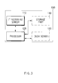
- FIG. 3 is a block diagram illustrating an electronic device according to an embodiment of the present disclosure.
- an electronic device 100 is illustrated, where the electronic device 100 may include a fingerprint sensor 110 and a processor 120. According to various embodiments of the present disclosure, the electronic device 100 may further include a touch screen 130 and/or a storage part 140.
- the electronic device 100 may recognize a fingerprint by controlling an operation of the fingerprint sensor 110 in accordance with a distance between the fingerprint and a sensing area if an image of the fingerprint is distorted or indistinct due to a curve of the sensing area.
- a curved sensing area practiced in the present specification may include all of uneven types as well as slope, curved, or asymmetrical types. Therefore, an embodiment of the present disclosure may be applicable to all kinds of fingerprint sensors and electronic devices having uneven sensing area.
- the electronic device 100 may be any one of electronic devices such as a mobile phone, a smart phone, a laptop computer, a digital multimedia broadcasting terminal, a digital camera, a portable gaming terminal, a personal digital assistant (PDA), a navigation terminal, a tablet computer, a personal computer, and the like.
- the electronic device 100 may include an information communication unit, a multimedia unit, and an application unit.
- the fingerprint sensor 110 may detect a fingerprint in response to a control signal of the processor 120.
- the electronic device 100 may employ the fingerprint sensor 110 which is operable in an optical, radio-frequency, thermosensitive, and/or ultrasonic mode. Additionally, the electronic device 100 may employ a kind of the fingerprint sensor 110 which is combined with two or more recognition modes.
- the fingerprint sensor 110 may be classified into swipe and touch types in accordance with fingerprint sensing style.
- the fingerprint sensor 110 of the swipe type may recognize a gesture that a finger with a fingerprint by surface is positioned on the fingerprint sensor 110 and then swiped toward a predetermined direction.
- the fingerprint sensor 110 of the touch type may recognize a gesture that a finger with fingerprint by surface contacts on the fingerprint sensor 110 for a predetermined time.
- the description will focus on the fingerprint sensor 110 of the touch type.
- the present disclosure may not be restrictively embodied herein and may be also applicable to the fingerprint sensor 110 of the swipe type.
- the fingerprint sensor 110 may transfer sensor data, which is obtained through fingerprint detection, to the processor 120.
- the fingerprint sensor 110 may recognize a fingerprint based on a fingerprint input, only if a fingerprint is positioned in a sensing area.
- the processor 120 may not identify a fingerprint if the fingerprint input is weak or indistinct. As a distance increases between the fingerprint 10 and the sensing area 20, as illustrated in FIG. 2D , it may be more difficult for the fingerprint sensor 110 to obtain the fingerprint input that is identifiable.
- the processor 120 may obtain a position where a fingerprint is not recognized in the sensing area 20 (hereinafter referred to as a 'fingerprint-unrecognizable position'). According to an embodiment, the processor 120 may obtain a point of the sensing area 20, at which a signal value detected from a receiver of the fingerprint sensor 110 becomes lower than a predetermined value, as a fingerprint-unrecognizable position for the fingerprint.
- the processor 120 may obtain a fingerprint-unrecognizable position from the sensing area 20.
- the fingerprint sensor 110 may be built into the touch screen 130.
- the touch screen 130 may be a flexible touch screen.
- the processor 120 may detect a touch input on the sensing area 20 through the touch screen 130.
- the processor 120 may obtain the fingerprint-unrecognizable position based on such a touch input.
- the processor 120 may obtain a fingerprint image from the fingerprint 10 through fingerprint detection and then obtain a fingerprint-unrecognizable position based on the fingerprint image.
- the processor 120 may obtain such a fingerprint-unrecognizable position based on resolution, contrast, image quality, and the like.
- a manner of obtaining a fingerprint-unrecognizable position by the processor 120 may not be restrictive to the aforementioned ways. It can be seen by those ordinarily skilled in the art that the processor 120 may obtain a fingerprint-unrecognizable position through various ways.
- the processor 120 may obtain a distance from a fingerprint-unrecognizable position of the sensing area 20 to the fingerprint 10, and then, based on the distance, control the fingerprint sensor 110 to adjust a sensing operation.
- the processor 120 may obtain a horizontal distance from a reference line, which is vertical to the sensing area 20, to the fingerprint-unrecognizable position and then, based on the horizontal distance, and curvature angle and radius of a curve, obtain a distance between the sensing area and a fingerprint. This will be described in more detail in conjunction with FIGS. 7 , 8A and 8B .
- the processor 120 may control the fingerprint sensor 110 to adjust at least one of a signal value, which is detected from a receiver of the fingerprint sensor 110, and power of a transmitter of the fingerprint sensor 110.
- the fingerprint sensor 110 may resume fingerprint detection after adjusting a sensing operation. This will be described in more detail in conjunction with FIGS. 9A and 9B .
- the processor 120 may obtain a fingerprint image which is obtained by detecting the fingerprint 10 through the fingerprint sensor 110.
- the processor 120 may perform image processing to the fingerprint image.
- the processor 120 may perform fingerprint authentication to determine whether the fingerprint 10 obtained by a sensing operation is a registered fingerprint. According to an embodiment, the processor 120 may compare a detected fingerprint image with a registered fingerprint image, and then determine a coincidence between an obtained fingerprint image (i.e., the detected fingerprint image) and the registered fingerprint image. Otherwise, the processor 120 may use a feature, which is extracted from a fingerprint image, to determine a coincidence with the registered fingerprint. Additionally, the processor 120 may use a variety of fingerprint authentication techniques.
- the processor 120 may be formed of at least one or more processors.
- the touch screen 130 may display a screen in response to a control signal of the processor 120 and detect a touch input on the screen.
- the touch screen 130 may transfer a detected touch input to the processor 120.
- the processor 120 may thereby control to perform a specific function corresponding to a user's touch input.
- the touch screen 130 may include a flexible touch screen.
- the fingerprint sensor 110 according to an embodiment may be built in a flexible touch screen.
- the touch screen 130 may detect a touch input by the fingerprint 10 from the sensing area 20. Then, the processor 120 may obtain a fingerprint-unrecognizable position based on a touch input on the touch screen 130.
- the touch screen 130 may find a fingerprint position on a sensing area of the fingerprint sensor 110. Additionally, the touch screen 130 may display a feedback to a fingerprint position, based on the found fingerprint position. This will be described in more detail in conjunction with FIGS. 11A and 11B .
- the touch screen 130 may display an icon of at least one application which is executed by fingerprint authentication at a position of a sensing area of the fingerprint sensor 110. Accordingly, the processor 120 may execute at least one application by fingerprint authentication of the fingerprint sensor 110.
- the touch screen 130 may use sensors, which are provided on the surface of the touch screen 130, to convert state changes of the sensors, such as pressure, electrostatic capacitance, optical intensity, and the like, into electric signals for touch input detection.
- the touch screen 130 according to an embodiment may be implemented in various ways such as resistance, electrostatic capacitance, ultrasonic wave, infrared ray, etc.
- the storage part 140 may be, for example, a general storage medium, and may store data or programs necessary for recognizing and authenticating the fingerprint 10 by the fingerprint sensor 110.
- the storage part 140 may store a fingerprint which is registered through the fingerprint sensor 110 and the processor 120. Additionally, the storage part 140 may store data or programs necessary for displaying a screen and detecting a touch input in the touch screen 130. Additionally, the storage part 140 may store program routines or instruction sets necessary for enabling the processor 120 to control the fingerprint sensor 110 or the touch screen 130.
- the storage part 140 may store data or programs necessary for operations of the electronic device 100.
- the storage part 140 may be implemented in a hard disk drive (HDD), a read-only memory (ROM), a random access memory (RAM), a flash memory, a memory card, a Negative-AND (NAND) memory, and/or a solid state drive (SSD).
- HDD hard disk drive
- ROM read-only memory
- RAM random access memory
- flash memory a flash memory
- memory card a memory card
- NAND Negative-AND
- SSD solid state drive
- FIG. 4 is a block diagram illustrating an electronic device according to an embodiment of the present disclosure.
- an electronic device 100 is illustrated, where the electronic device 100 may be formed of a storage part 140 and a fingerprint processing module 150.
- the fingerprint processing module 150 may be formed of an image processing part 151 and a fingerprint authenticating part 152.
- a fingerprint sensor 110 may detect an object with a predetermined permittivity. Further, the fingerprint sensor 110 may transfer sensor data, which is obtained through a sensing operation, to the fingerprint processing module 150.
- the storage part 140 which may be a general storage medium, may store a fingerprint which is registered through the fingerprint sensor 110 and the fingerprint processing module 150. Additionally, the storage part 140 may store data or programs necessary for performing image processing of sensor data and determining whether a recognized fingerprint is a registered fingerprint.
- the fingerprint processing module 150 may receive the sensor data, which is obtained from the fingerprint sensor 110, perform image processing of the received sensor data, and perform fingerprint authentication.
- the fingerprint processing module 110 may correspond to at least one or more processors, or may be driven in a condition of belonging to an application processor (AP) or another processor (not shown).
- AP application processor
- the image processing part 151 may receive the sensor data, which is obtained from the fingerprint sensor 110, and reform the received sensor data into an image.
- the image processing part 151 may transfer the reformed image to the fingerprint authenticating part 152.
- the image processing part 151 may be formed of an image reforming part 1511 and a minutia extracting part 1512.
- the image reforming part 1511 may combine sensor data to reform a fingerprint image.
- the minutia extracting part 1512 may extract minutia information, which is used for finding inherent characteristics of a fingerprint, from a reformed fingerprint image.
- the minutia extracting part 1512 may generate a template based on the extracted minutia information.
- the image processing part 151 may display minutia information in a reformed fingerprint image through an image processing operation, and use the fingerprint image, in which the minutia information is displayed, as a template.
- the fingerprint authenticating part 152 may perform a fingerprint authentication processing to a recognized fingerprint.
- the fingerprint authentication processing may be a series of operations for performing fingerprint authentication.
- the fingerprint authenticating part 152 may perform the fingerprint authentication processing to determine whether there is a registered fingerprint identical to a recognized fingerprint.
- the fingerprint authenticating part 152 may include a matching part 1521.
- the fingerprint authenticating part 152 may receive the minutia information, a fingerprint image, and/or a template. Based on at least one of the received minutia information, the fingerprint image, and/or the template, the matching part 1521 may determine whether a recognized fingerprint is identical to a registered fingerprint. For example, the matching part 1521 may calculate a similarity between a template of a registered fingerprint and a template which is received from the image processing part 151, and thereby determine whether the recognized fingerprint is identical to the registered fingerprint. Otherwise, the matching part 1521 may calculate similarity between an image of the registered fingerprint and an image which is received from the image processing part 151, and thereby determine whether the recognized fingerprint is identical to the registered fingerprint.
- FIGS. 5A, 5B, 5C and 5D are diagrams illustrating an operation of performing fingerprint authentication in an electronic device according to various embodiments of the present disclosure.
- FIG. 5A a fingerprint image is illustrated, where the fingerprint image is reformed by the image reforming part 1511, as illustrated in FIG. 4 .
- a fingerprint is generally shaped in ridges and valleys between the ridges.
- minutia are illustrated, where the minutia are extracted by the minutia extracting part 1521.
- the minutia extracting part 1521 may extract branches of ridges, endpoints of ridges, and the like as minutia thereof.
- a process of generating a template is illustrated, where the template is generated based on minutia information which are extracted by the minutia extracting part 1512.
- the minutia extracting part 1512 may form the extracted minutia into a template.
- the fingerprint processing module 150 may store data, which is generated for the template, into a database (DB).
- DB database
- Fingerprint data obtained from the fingerprint sensor may be stored in a form of an image, extracted minutia, or a combination of thereof, as well as in a form of the template.
- FIGS. 6A, 6B, 6C and 6D are diagrams illustrating an operation of performing fingerprint authentication in an electronic device according to various embodiments of the present disclosure.
- the matching part 1521 may perform a fingerprint authentication processing to an input fingerprint.
- the matching part 1521 may calculate a score about relativity between an input fingerprint and a registered fingerprint, and determine that the input fingerprint matches with a registered fingerprint if the score is higher than a threshold level.
- a first template 13 is illustrated, where the first template 13 includes minutia information of a registered fingerprint.
- a second template 14 is illustrated, where the second template 14 includes minutia information of an input fingerprint.
- the matching part 1521 may match the first template 13 with the second template 14, and calculate a score about similarity between an input fingerprint and a registered fingerprint.
- the matching part 1521 may use a function of an overlap area OA between the first template 13 and the second template 14, a minutia number N common to the first template 13 and the second template 14, registered minutia information E, and authenticated minutia information V to calculate a score therefrom, and then, based on the calculated score, may determine similarity between an input fingerprint and a registered fingerprint.
- the matching part 1521 may determine that an input fingerprint matches with a registered fingerprint if the calculated score is higher than a threshold level, and then authenticate the input fingerprint.
- a threshold level is illustrated, where the threshold level acts as a reference for determining similarity, may be a value set dependent on a fingerprint misrecognition rate.
- FIG. 6D is a graphic diagram illustrating a relativity between a fingerprint misrecognition rate and a threshold level.
- the graph shows possibilities of determining fingerprint mismatch along scores.
- the graph shows possibilities of determining fingerprint matches along scores.
- the threshold level may be determined on a point where the two graphs meets each other.
- the left field indicates a false reject rate (FRR) that determines a fingerprint mismatch even though an input fingerprint is identical to a registered fingerprint.
- FRR false reject rate
- the right field indicates a false accept rate (FAR) that determines a fingerprint match even though an input fingerprint is different from a registered fingerprint.
- FAR false accept rate
- FIG. 7 is a diagram illustrating an operation of recognizing a fingerprint in an electronic device according to an embodiment of the present disclosure.
- the processor 120 may obtain a position P at which a fingerprint is not recognized due to a curve of a sensing area 20 of the fingerprint sensor 120.
- the processor 120 may obtain a distance v that ranges to a fingerprint 10 from the position P on the sensing area 20, and then, based on the distance v, control the fingerprint sensor 110 to adjust a sensing operation of the fingerprint sensor 110.
- the processor 120 may obtain the distance v by way of the following process.
- the processor 120 may obtain a horizontal distance h that ranges to the position P from a reference line 30 which is vertical to the sensing area 20. While an embodiment of the present disclosure is illustrated as the reference line 30 is set on the center of curve of the sensing area 20, the present disclosure may not be restrictive hereto in various embodiments thereof.
- the reference line 30 may be set, not on the center of curve of the sensing area 20, even on another position that is vertical to the sensing area 20.
- the reference line 30 may be set on an appropriate location, which is vertical to the sensing area 20, depending on a shape of curve of the sensing area 20.
- a location of the reference line 30 may be set in advance. Otherwise, a location of the reference line 30 may be set by the processor 120 during fingerprint recognition. According to this, the processor 120 may set a location of the reference line 30 based on at least one of a touch input, which is received through the fingerprint sensor 110, and a fingerprint image which is obtain from the fingerprint sensor 110.
- the processor 120 may obtain a horizontal distance h from the reference line 30 to the position P.
- the processor 120 may obtain the distance v from the horizontal distance h, and a curvature angle ⁇ and a curvature radius r of a curve to the position P from the reference line 30 of the sensing area 20.
- Equation 1 may be summarized to result in Equation 2 for calculating the distance v, as follows.
- v 2 ⁇ r 2 - 2 ⁇ r 2 ⁇ cos ⁇ - h 2
- the distance v may be given by an equation involved in the horizontal distance h, the curvature radius r, and the curvature angle ⁇ .
- the curvature angle ⁇ and the curvature radius r may be preliminarily valued in accordance with a shape of curve of the sensing area 20.
- the storage part 140 may preliminarily store values of the curvature radius r and the curvature angle ⁇ that correspond to respective positions of the sensing area.
- the curvature angle ⁇ and the curvature radius r which correspond to the position P, may be determined by the processor 120 in accordance with a shape and curvature of curve of the sensing area during execution of fingerprint recognition.
- the processor 120 may act to control a sensing operation of the fingerprint sensor 110.
- the processor 120 may control the fingerprint sensor 110, based on the distance v, to adjust at least one of detected signal value and amplification gain.
- the processor 120 may control the fingerprint sensor 110 to adjust transmission power of a transmitter in correspondence with the position P.
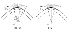
- FIGS. 8A and 8B are diagrams illustrating a recognizing of a fingerprint in an electronic device according to an embodiment of the present disclosure.
- FIG. 8A an operation is illustrated, where the operation calculates a distance to an area that is out of a fingerprint recognition range in the electronic device 100, as illustrated in FIG. 4 .
- the processor 120 may obtain a plurality of positions P1, .., Pm, Pm+1, .., and Pn (hereinafter abbreviated to P1 ⁇ Pn) which are located within an area where any fingerprint cannot be recognized.
- the electronic device 100 may obtain curvature angles ⁇ 1, .., ⁇ m, ⁇ m+1, ..., and ⁇ n, with reference to a reference line 30, and distances V1, .., Vm, Vm+1, .., and Vn (hereinafter abbreviated to as V1 ⁇ Vn) respective to the plural positions P1 ⁇ Pn by obtaining the fingerprint-unrecognizable position P and repeating a process of obtaining the distance to a fingerprint 10 from the position P of a sensing area 20.
- the processor 120 may control the fingerprint sensor 110 to adjust at least one of a signal value, which is detected from a receiver of the fingerprint sensor 110 in correspondence with each of the plural positions P1 ⁇ Pn, transmission power of a transmitter of the fingerprint sensor 110, and an amplification gain of the transmitter.
- the processor 120 may control the fingerprint sensor 110 to increase at least one of a signal value, which is detected from a receiver of the fingerprint sensor 110, an amplification gain of the receiver, and transmission power of a transmitter of the fingerprint sensor 110. Accordingly, it may be allowable to vary a signal value, which is detected from a receiver of the fingerprint sensor 110, an amplification gain of the receiver, and transmission power of a transmitter of the fingerprint sensor 110.
- FIG. 8B an operation of detecting a fingerprint 10 is illustrated, where the operation uses a sensing area 20 to calculate a distance to a fingerprint-unrecognizable area in the electronic device 100, as illustrated in FIG. 4 , based on a reference line 30.
- the processor 120 may obtain boundary positions B1 and B2 on an area corresponding to the fingerprint-unrecognizable area.
- the electronic device 100 may obtain the distances V1 and V2 respective to the boundary positions B1 and B2. Accordingly, the processor 120, based on the distances V1 and V2 of the boundary positions B1 and B2, may estimate the plural distances V1 ⁇ Vn respective to the plural positions P1 ⁇ Pn in accordance with the plural positions P1 ⁇ Pn on the fingerprint-unrecognizable area.
- the processor 120 may determine at least one of a signal value, which is detected from a receiver of the fingerprint sensor 110, as illustrated in FIG. 3 , an amplification gain of the receiver, and transmission power of a transmitter of the fingerprint sensor 110, respective to the plural positions P1 ⁇ Pn on a fingerprint-unrecognizable area in accordance with the plural positions P1 ⁇ Pn of the fingerprint-unrecognizable area. Accordingly, it may be allowable to vary a signal value, which is detected from a receiver of the fingerprint sensor 110, an amplification gain of the receiver, and transmission power of a transmitter of the fingerprint sensor 110.
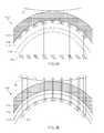
- FIGS. 9A and 9B are diagrams illustrating a feature of adjusting a sensing operation of a fingerprint sensor in an electronic device according to various embodiments of the present disclosure.
- an operation is illustrated, where the operation includes adjusting a signal value which is detected from a receiver of a fingerprint sensor 110 in the electronic device 100, as illustrated in FIG. 4 .
- the fingerprint sensor 110 may be formed of a cover 111, an insulation layer 112, a reception part 113, a transmission part 114, and an amplification part 115.
- the fingerprint sensor 110 may further include other general elements in addition to these elements shown in FIG. 9A .
- the reception part 113 may include a plurality of receivers R1, R2, .., and R9 (R1 ⁇ R9) which are arranged along the sensing area 20, as illustrated in FIG. 2 .
- the receivers R1 ⁇ R9 may respectively act as sensing electrodes.
- the processor 120 may adjust a signal value which is detected from the receiver corresponding to the position.
- the processor 120 may adjust amplification gains of amplifiers A1, A2, .., and A9 (A1 ⁇ A9) coupled with the receivers corresponding to the positions.
- FIG. 9A illustrates that the plural amplifiers A1 ⁇ A9 are coupled one by one with the receivers, whereas the present disclosure may not be restrictive hereto in embodiments.
- the plural receivers may be coupled with a single amplifier which is capable of adjusting amplification gains of the receivers.
- the processor 120 may adjust signal values, which are detected from the receivers corresponding respectively to the plural positions, or amplification gains of the receivers based on distances of the plural positions.
- Signal values detected from the receivers corresponding each to a plurality of the positions of the fingerprint-unrecognizable area, or amplification gains of the receivers, may be determined in proportion respectively to the plural positions.
- the processor 120 may control the fingerprint sensor 110 to increase signal values detected from the receivers of the fingerprint sensor 110, and amplification gains of the receivers 110 as large as the distances.
- the processor 120 by adding weights that respectively accord to distances respective to a plurality of positions of a fingerprint-unrecognizable area, may determine signal values, which are detected from the receivers corresponding respectively to the plural positions, and amplification gains of the receivers. For example, as a fingerprint surface 10 of a finger is uneven, the processor 120 may add a weight to each distance of each fingerprint-unrecognizable position, and thereby control the fingerprint sensor 110 to increase a signal value or amplification gain that is detected from the receiver of the fingerprint sensor 110.
- signal values which are detected from the receivers of the fingerprint sensor 110, depending on positions of the sensing area.
- an operation is illustrated, where the operation includes adjusting transmission power of a transmitter of a fingerprint sensor 110 in the electronic device 100, as illustrated in FIG. 4 .
- the fingerprint sensor 110 may be formed of a cover 111, an insulation layer 112, a reception part 116, and a transmission part 117.
- the fingerprint sensor 110 may further include other general elements in addition to these elements shown in FIG. 9B .
- the fingerprint sensor 110 may include a plurality of transmitters T1, T2, .., and T9 (T1 ⁇ T9) which are arranged along the sensing area 20, as illustrated in FIG. 2 .
- the plural transmitters T1 ⁇ T9 may act respectively as sensing electrodes.
- the processor 120 may adjust transmission power of the transmitter corresponding to the position.
- the processor 120 may adjust transmission power of the transmitters, which correspond respectively to the plural positions, based on distances respective to the plural positions.
- Transmission power of the transmitters corresponding respectively to the plural positions of the fingerprint-unrecognizable area may be determined in proportion each to the distances respective to the plural positions.
- the processor 120 may control the fingerprint sensor 110 to increase transmission power of the transmitters as large as the distances.
- the processor 120 by adding weights that respectively accord to distances respective to a plurality of positions of a fingerprint-unrecognizable area, may determine transmission power of the transmitters corresponding respectively to the plural positions. For example, as a fingerprint surface 10 of a finger is uneven, the processor 120 may add a weight to each distance of each fingerprint-unrecognizable position, and thereby control the fingerprint sensor 110 to increase transmission power of the transmitter.
- it may be allowable to vary transmission power of the transmitters of the fingerprint sensor 110 in correspondence with positions of the sensing area.
- FIGS. 10A, 10B and 10C are diagrams illustrating an operation of performing fingerprint recognition in an electronic device, which is equipped with a fingerprint sensor at a side thereof, according to various embodiments of the present disclosure.
- FIGS. 10A to 10C illustrate a mobile terminal having the fingerprint sensor 110, as illustrated in FIG. 3
- an embodiment of the present disclosure may not be restrictive to such a mobile terminal and may also include any kind of electronic device 100 which is equipped with a fingerprint sensor.
- the electronic device 100 may include a curve at a side part thereof.
- the fingerprint sensor 110 may be placed at a side of the electronic device 100.
- the electronic device 100 may adjust a sensing operation of the fingerprint sensor 110 corresponding to fingerprint-unrecognizable positions that are caused from the curve and thereby may accomplish to distinctly recognize the fingerprint.
- the electronic device 100 may distinctly recognize a fingerprint even though various shapes of curves are present in a sensing area of the fingerprint sensor.
- a side part of the electronic device 100 may be formed of a touch screen 130.
- the touch screen 130 may be a kind of flexible touch screen. Accordingly, the fingerprint sensor 110 may be equipped in such a flexible touch screen.
- the fingerprint sensor 110 shown in FIGS. 10A to 10C is illustrated as being located on a side of a mobile terminal or the electronic device 100, whereas various embodiments of the present disclosure may not be restrictive hereto. Additionally, the fingerprint sensor 110 may be placed at a location, which includes a curve, for example, a rear, front, upper, or lower side of a mobile terminal or the electronic device 100.
- FIGS. 11A and 11B are diagrams illustrating a feature of providing a feedback to a fingerprint position on a sensing area in an electronic device according to various embodiments of the present disclosure.
- the fingerprint sensor 110 may be placed at a side of the electronic device 100.
- a side part of the electronic device 100 may include a curve.
- the processor 120 may identify a fingerprint area, on the sensing area, into which a fingerprint input of a finger is received.
- the processor 120 may compare the centers of curves to one another between the fingerprint area and the sensing area, and then, based on a result of the comparison, provide the user with a feedback that relates to a position of the fingerprint.
- the touch screen 130 may display a direction and degree of the fingerprint area, which is out of a range from the sensing area, in a predetermined form.
- the predetermined form may be made of a shadow 40 which has a pattern of fingerprint.
- the predetermined form may be available in all visible kinds such as lighting, static image, dynamic image, and the like.
- the processor 120 may provide sound or haptic data together with a predetermined form.
- the touch screen 130 may include a flexible touch screen.
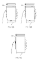
- the processor 120 may control a feedback, which relates to a fingerprint position, to be displayed on a screen in a predetermined form. If a fingerprint position is inclined frontward from the center of curve of a sensing area as shown in the right of FIG. 11A , the touch screen 130 may display a shadow 40, which shows that the position of the fingerprint is inclined frontward, at a side where a hand is located as shown in FIG. 11A .
- the touch screen may display a shadow 40, which is patterned in a shape of fingerprint to show that the position of the fingerprint is shifted backward, at the counter side of a location of a hand as shown in FIG. 11B .
- the electronic device 100 may provide a feedback in accordance with a fingerprint position on a sensing area and thereby complete fingerprint recognition of the fingerprint sensor 110.
- a user may be able to refer to a feedback, which relates to a fingerprint position displayed at the front of the electronic device 100, and identify the position of the fingerprint even without turning a direction of the electronic device 100 toward its side. Accordingly, it may improve the facility for a user.
- An embodiment of the present disclosure is described as the electronic device 100 determines whether a fingerprint position is out of a range from a sensing area on the center of curve.
- various embodiments of the present disclosure may not be restrictive hereto.
- the electronic device 100 may also determine whether a fingerprint position is out of a range from a sensing area on a predetermined position in accordance with a pattern of curve of the sensing area.
- the fingerprint sensor 110 discussed in relation to FIGS. 11A and 11B is illustrated as being located at a side of a mobile terminal or the electronic device 100, whereas the various embodiments of the present disclosure may not be restrictive hereto.
- the fingerprint sensor 110 may be placed at a location, which includes a curve, such as a rear, front, upper, or lower side of a mobile terminal or the electronic device 100.
- FIG. 12 is a diagram illustrating a feature of performing fingerprint authentication in a flexible touch screen including a fingerprint sensor according to an embodiment of the present disclosure.
- a fingerprint sensor 110 may be built in a touch screen 130.
- the fingerprint sensor 110 according to an embodiment of the present disclosure may be placed at a side part of the electronic device 100.
- the side part of the electronic device 100 may include a curve.
- the touch screen 130 may display an icon of at least one application which is executed by fingerprint authentication at a position of a sensing area of the fingerprint sensor 110.
- the touch screen 130 according to an embodiment of the present disclosure may be a flexible touch screen. Accordingly, the fingerprint sensor 110 may be built in a flexible touch screen.
- the electronic device 100 may perform an operation to recognize the user's fingerprint. If fingerprint authentication is accomplished, the electronic device 100 executes the icon corresponding thereto.
- the electronic device 100 may display an icon of an application, which uses fingerprint authentication, at a position of a sensing area, and control to execute the application by fingerprint authentication for a user.
- an icon of an application using fingerprint authentication is disposed at a side of the electronic device 100 to enable a user to perform a fingerprint sensing operation at the same time when the user is gripping the electronic device 100. Accordingly, the user may be able to immediately execute an application, which needs security authentication, without an additional handling for fingerprint recognition by making a fingerprint of a finger, which is gripping the electronic device 100, to be detected on a sensing area. Thus, it may improve user facility.
- the fingerprint sensor 110 of FIG. 12 is illustrated as being located at a side of a mobile terminal or the electronic device 100, whereas various embodiments of the present disclosure may not be restrictive hereto. Additionally, the fingerprint sensor 110 may be placed at a location, which includes a curve, such as a rear, front, upper, or lower side of a mobile terminal or the electronic device 100.
- FIG. 13 is a diagram illustrating a feature of performing a plurality of icons, which are located in a same row with a fingerprint authentication position, by fingerprint authentication of a fingerprint sensor placed at a side of an electronic device according to an embodiment of the present disclosure.
- a fingerprint sensor 110 may be placed at a side part of the electronic device 100.
- the side part of the electronic device 100 may include a curve.
- a touch screen 130 may be placed at a front part of the electronic device 100 and display an icon 50 of at least one application, which is executed with fingerprint authentication, in a single row.
- the electronic device 100 may perform recognition for the fingerprint of the user. If fingerprint authentication is accomplished, the electronic device 100 an application corresponding to the icon 50 located in the same row with the sensing area.
- the electronic device 100 may display the icons 50 of a plurality of applications in the same row and control the plural applications to be coincidently executed by one-time fingerprint authentication of a user.
- the electronic device 100 may perform fingerprint authentication for a plurality of applications at a same time by disposing the icons of the plural applications, which use fingerprint authentication, in a line at a front part of the electronic device 100 and then operating the fingerprint sensor, which is placed at the side, while a user is gripping the electronic device 100.
- a user may be able to perform an authentication for a plurality of applications, which need security authentication, at a time, without repetitive fingerprint recognition respective to the plural applications, by way of one-time fingerprint sensing operation with a finger which is gripping the electronic device 100. Therefore, it may improve user facility.
- the fingerprint sensor 110 of FIG. 13 is illustrated as placing at a side of a mobile terminal or the electronic device 100, whereas various embodiments of the present disclosure may not be restrictive hereto. Additionally, the fingerprint sensor 110 may be placed at a location, which includes a curve, such as a rear, front, upper, or lower side of a mobile terminal or the electronic device 100.
- FIGS. 14A and 14B are diagrams illustrating a feature of arranging icons of applications, which use fingerprint authentication, in a same row with a fingerprint authentication position by fingerprint recognition of a fingerprint sensor placed at a side of an electronic device according to various embodiments of the present disclosure.
- a fingerprint sensor 110 may be placed at a side part of an electronic device 100.
- the side part of the electronic device 100 may include a curve.
- a touch screen 130 may be placed at a front part of the electronic device 100 and display an icon of at least one application which is executed by fingerprint authentication. During this, icons of at least one application executed by fingerprint authentication may be dispersed to locate over the touch screen 130 as shown in FIG. 14A .
- the fingerprint sensor 110 of the electronic device 100 may recognizes the fingerprint. If the fingerprint is recognized by the fingerprint sensor 110, the electronic device 100 may arrange icons of at least one application, which disperse over the touch screen 130 and use fingerprint authentication, in a row 60, as illustrated in FIG. 14B .
- the processor 120 may control icons of applications, which use fingerprint authentication, in a same row with a position at which the fingerprint is recognized.
- the electronic device 100 may collect a plurality of icons of applications, which are dispersed and use fingerprint authentication, in the single row 60 by the fingerprint recognition. Accordingly, the electronic device 100 may provide information about an application, which uses fingerprint authentication, for a user. Additionally, if icons of a plurality of applications using fingerprint authentication are displayed in the same row 60, a user may be able to coincidently execute the plural applications.
- the fingerprint sensor 110 is placed at a side of the electronic device 100, the fingerprint sensor 110 placed at the side may operate while a user is gripping the electronic device 100. If the fingerprint sensor 110 recognizes a fingerprint, icons of a plurality of applications using fingerprint authentication may be rearranged in a line at a front part of the electronic device 100.
- a user after finding icons of a plurality of applications using fingerprint authentication, may continue to operate the fingerprint sensor 110, while he is gripping the electronic device 100, and thereby coincidently execute the fingerprint authentication for the rearranged applications.
- a user may be able to rearrange the application icons in a single row only by a simple handling of operating the fingerprint sensor 110. Therefore, it may improve user facility because a user may easily find application icons, which use fingerprint authentication, from a plurality of icons displayed in the screen by a simple operation.
- the fingerprint sensor 110 of FIGS. 14A and 14B is illustrated as being located at a side of a mobile terminal or the electronic device 100, whereas various embodiments of the present disclosure may not be restrictive hereto. Additionally, the fingerprint sensor 110 may be placed at a location, which includes a curve, such as a rear, front, upper, or lower side of a mobile terminal or the electronic device 100.
- FIGS. 15A and 15B are diagrams illustrating a feature of displaying hidden icons, which are relevant to privacy of a user, in a same row with a fingerprint authentication position by fingerprint authentication of a fingerprint sensor placed at both sides of an electronic device according to various embodiments of the present disclosure.
- an electronic device 100 according to an embodiment of the present disclosure is illustrated, where the electronic device 100 may be designed to place at least two fingerprint sensors 110 at both sides of the electronic device 100.
- a side part of the electronic device 100 may include a curve.
- a touch screen 130 may locate at a front part of the electronic device 100 and display an icon of an application.
- the electronic device 100 may perform fingerprint recognition in each of the both-sided fingerprint sensors 110. If fingerprint authentication is accomplished for the two fingerprints, the electronic device 100 may perform a predetermined function relevant to security requirement or user privacy.
- a predetermined function with a very high security level may be performed.
- the processor 120 may operate to approve a financial service.
- the processor 120 may display a hidden icon on the touch screen 130, as illustrated in FIG. 15B .
- the hidden icon as a kind of icon which is expressed, but normally disappearing, on a screen if authentication is performed for at least two fingerprints, may be a secret album or folder involved in privacy of a user, or a financial business icon needing security.
- the electronic device 100 may operate to perform a predetermined function with very high security level by authenticating at least two or more fingerprints at the same time.
- the fingerprint sensors 110 are placed at both sides of the electronic device 100, a user may be able to coincidently operate the at least two fingerprint sensors 110, which are placed at both sides, while the user is gripping the electronic device 100. If the fingerprint sensors 110 coincidently detect at least two fingerprints, the electronic device 100 may display at least one secret icon in a same row 70 with a position where a fingerprint is recognized.
- a user may be able to easily conduct a fingerprint sensing operation in one time with at least two fingers which are gripping the electronic device 100.
- the fingerprint sensors 110 of FIGS. 15A and 15B are illustrated as being located at both sides of a mobile terminal or the electronic device 100, whereas various embodiments of the present disclosure may not be restrictive hereto. Additionally, the fingerprint sensor 110 may be placed at a location, which includes a curve, such as a rear, front, upper, or lower side of a mobile terminal or the electronic device 100.
- FIG. 16 is a flow chart showing a fingerprint recognition method according to an embodiment of the present disclosure.
- a fingerprint recognition method includes operations that are processed by time variation in the electronic device 100 of FIGS. 3 to 15B . Therefore, it can be seen that the aforementioned descriptions relevant to the electronic device 100 shown in FIGS. 3 to 15B may be also applicable to the flow chart shown in FIG. 16 even though those descriptions will not be further duplicated hereinafter.
- the electronic device 100 may obtain a fingerprint-unrecognizable position from a sensing area of the fingerprint sensor 110, as illustrated in FIG. 3 .
- the sensing area may be an area from which the fingerprint sensor 110 obtains a fingerprint input. If a fingerprint is placed on a sensing area of the fingerprint sensor 110, the fingerprint sensor 110 obtains a fingerprint input and then, based on the fingerprint input, recognize the fingerprint.
- the processor 120 may not identify the fingerprint if the fingerprint input is so weakly present or indistinct.
- the electronic device 100 may obtain a distance to a fingerprint from a fingerprint-unrecognizable position on a sensing area.
- the electronic device 100 may obtain a horizontal distance to a fingerprint-unrecognizable position from a reference line that is vertical to a sensing area, and thereafter, based on the horizontal distance, and a curvature angle and a curvature radius of a curve, obtain a distance between a fingerprint and the fingerprint-unrecognizable position.
- the reference line, the curvature angle, and the curvature radius may be preliminarily determined. Otherwise, the reference line, the curvature angle, and the curvature radius may be determined during fingerprint recognition.
- the electronic device 100 may adjust a sensing operation of the fingerprint sensor 110. For example, based on the distance, the processor 120 may control the fingerprint sensor 110 to adjust at least one of a signal value, which is detected by a receiver of the fingerprint sensor 110, and transmission power of a transmitter of the fingerprint sensor 110.
- FIG. 17 is a flow chart showing a fingerprint recognition method according to the present disclosure.
- a fingerprint recognition method is illustrated and includes operations that are processed by time variation in the electronic device 100 of FIGS. 3 to 15B . Therefore, it can be seen that the aforementioned descriptions relevant to the electronic device 100 shown in FIGS. 3 to 15B may be also applicable to the flow chart shown in FIG. 17 , even though those descriptions will not be further duplicated hereinafter.
- the electronic device 100 may confirm a fingerprint area which is an area receiving a fingerprint input of a fingerprint on a sensing area. If a user places a fingerprint on a sensing area, the processor 120, as illustrated in FIG. 3 , may confirm a fingerprint area on the sensing area.
- the electronic device 100 may compare a fingerprint area with the center of curve of a sensing area.
- An embodiment of the present disclosure is described as the electronic device 100 determines whether a fingerprint position is out of range from a sensing area on the center of curve.
- various embodiments of the present disclosure may not be restrictive hereto.
- the electronic device 100 may determine whether a fingerprint position is out of range from a sensing area on a predetermined location according to a pattern of curve of the sensing area.
- the electronic device 100 may provide a feedback, which is involved in a fingerprint position, to a flexible touch screen. According to an embodiment, if a fingerprint position is out of range from the center of curve of a sensing area, the electronic device 100 may display an out of range direction and degree of the fingerprint position from the sensing area in a predetermined form.
- the predetermined from may be a shadow 40, as illustrated in FIG. 11B , that is shaped in a fingerprint.
- a predetermined form of displaying an out of range direction and degree of a fingerprint position from a sensing area may include any one of visible forms such as lighting, static image, dynamic image, and the like.
- the processor 120 may provide sound or haptic data together with a predetermined pattern.
- the computer-readable recording medium may include a magnetic recording medium (e.g., read-only memory (ROM), floppy disk, hard disk, etc.), an optical readout medium (e.g., compact disc ROM (CD-ROM), or digital versatile disc (DVD).
- ROM read-only memory
- CD-ROM compact disc ROM
- DVD digital versatile disc
- a fingerprint sensor it may be allowable to recognize a fingerprint from an electronic device even though an area where a fingerprint senor detects the fingerprint. Therefore, it may be applicable for a fingerprint sensor to be without limits to space even in an electronic device including diverse patterns of curves. Additionally, it may be practicable to form a flexible display apparatus including a fingerprint.
- a fingerprint By placing a fingerprint at a side of an electronic device, it may be permissible to raise spatial practicability. Additionally, a user may be able to handle fingerprint authentication while griping an electronic device.
- a non-transitory computer readable recording medium is any data storage device that can store data which can be thereafter read by a computer system. Examples of the non-transitory computer readable recording medium include ROM, Random-Access Memory (RAM), CD-ROMs, magnetic tapes, floppy disks, and optical data storage devices.
- the non-transitory computer readable recording medium can also be distributed over network coupled computer systems so that the computer readable code is stored and executed in a distributed fashion. Also, functional programs, code, and code segments for accomplishing the present disclosure can be easily construed by programmers skilled in the art to which the present disclosure pertains.
- various embodiments of the present disclosure as described above typically involve the processing of input data and the generation of output data to some extent.
- This input data processing and output data generation may be implemented in hardware or software in combination with hardware.
- specific electronic components may be employed in a mobile device or similar or related circuitry for implementing the functions associated with the various embodiments of the present disclosure as described above.
- one or more processors operating in accordance with stored instructions may implement the functions associated with the various embodiments of the present disclosure as described above. If such is the case, it is within the scope of the present disclosure that such instructions may be stored on one or more non-transitory processor readable mediums.
- processor readable mediums examples include ROM, RAM, CD-ROMs, magnetic tapes, floppy disks, and optical data storage devices.
- the processor readable mediums can also be distributed over network coupled computer systems so that the instructions are stored and executed in a distributed fashion. Also, functional computer programs, instructions, and instruction segments for accomplishing the present disclosure can be easily construed by programmers skilled in the art to which the present disclosure pertains.
Landscapes
- Engineering & Computer Science (AREA)
- Theoretical Computer Science (AREA)
- Physics & Mathematics (AREA)
- General Physics & Mathematics (AREA)
- Human Computer Interaction (AREA)
- Multimedia (AREA)
- General Engineering & Computer Science (AREA)
- Computer Hardware Design (AREA)
- Computer Security & Cryptography (AREA)
- Computer Vision & Pattern Recognition (AREA)
- Software Systems (AREA)
- Image Input (AREA)
- Collating Specific Patterns (AREA)
Applications Claiming Priority (1)
| Application Number | Priority Date | Filing Date | Title |
|---|---|---|---|
| KR1020140056282A KR102212632B1 (ko) | 2014-05-12 | 2014-05-12 | 지문 인식 방법 및 이를 수행하는 전자 장치 |
Publications (2)
| Publication Number | Publication Date |
|---|---|
| EP2945097A1 true EP2945097A1 (fr) | 2015-11-18 |
| EP2945097B1 EP2945097B1 (fr) | 2022-06-29 |
Family
ID=53177175
Family Applications (1)
| Application Number | Title | Priority Date | Filing Date |
|---|---|---|---|
| EP15167174.0A Active EP2945097B1 (fr) | 2014-05-12 | 2015-05-11 | Procédé de reconnaissance d'empreintes digitales et dispositif électronique pour la mise en oeuvre de celui-ci |
Country Status (3)
| Country | Link |
|---|---|
| US (1) | US9934371B2 (fr) |
| EP (1) | EP2945097B1 (fr) |
| KR (1) | KR102212632B1 (fr) |
Cited By (5)
| Publication number | Priority date | Publication date | Assignee | Title |
|---|---|---|---|---|
| CN106951243A (zh) * | 2017-03-13 | 2017-07-14 | 华勤通讯技术有限公司 | 屏幕控制方法及终端设备 |
| DE102016101613A1 (de) * | 2016-01-29 | 2017-08-03 | Bundesdruckerei Gmbh | Authentifikationsvorrichtung und Verfahren zum Authentifizieren einer Person |
| CN109324706A (zh) * | 2017-07-31 | 2019-02-12 | 中兴通讯股份有限公司 | 一种触控识别的方法和装置 |
| EP3655874A4 (fr) * | 2017-09-20 | 2020-11-11 | Fingerprint Cards AB | Procédé et dispositif électronique d'authentification d'utilisateur |
| US11825726B2 (en) | 2019-05-10 | 2023-11-21 | Semiconductor Energy Laboratory Co., Ltd. | Display device and electronic device |
Families Citing this family (71)
| Publication number | Priority date | Publication date | Assignee | Title |
|---|---|---|---|---|
| US9400914B2 (en) * | 2014-10-24 | 2016-07-26 | Egis Technology Inc. | Method and electronic device for generating fingerprint enrollment data |
| US10481759B2 (en) * | 2014-12-29 | 2019-11-19 | Lg Electronics Inc. | Bended display device for controlling function of application through image displayed on sub-region, and control method therefor |
| KR102348486B1 (ko) * | 2015-04-29 | 2022-01-07 | 삼성전자 주식회사 | 전자 장치 |
| US10181020B2 (en) * | 2015-09-21 | 2019-01-15 | American Express Travel Related Services Company, Inc. | Systems and methods for gesture based biometric security |
| CN106951754B (zh) * | 2016-01-06 | 2018-08-31 | 阿里巴巴集团控股有限公司 | 一种信息图像显示方法及装置 |
| EP3208733B1 (fr) * | 2016-02-19 | 2020-07-01 | Sony Corporation | Dispositif, procédé et programme terminal |
| CN105760738B (zh) | 2016-03-15 | 2017-08-25 | 广东欧珀移动通信有限公司 | 一种指纹解锁的方法及终端 |
| KR102509067B1 (ko) * | 2016-04-08 | 2023-03-13 | 삼성디스플레이 주식회사 | 사용자 인증장치, 그것의 입력 센싱 모듈 및 사용자 인증방법 |
| US10656255B2 (en) | 2016-05-04 | 2020-05-19 | Invensense, Inc. | Piezoelectric micromachined ultrasonic transducer (PMUT) |
| US10315222B2 (en) | 2016-05-04 | 2019-06-11 | Invensense, Inc. | Two-dimensional array of CMOS control elements |
| US10670716B2 (en) | 2016-05-04 | 2020-06-02 | Invensense, Inc. | Operating a two-dimensional array of ultrasonic transducers |
| US10445547B2 (en) | 2016-05-04 | 2019-10-15 | Invensense, Inc. | Device mountable packaging of ultrasonic transducers |
| US10408797B2 (en) | 2016-05-10 | 2019-09-10 | Invensense, Inc. | Sensing device with a temperature sensor |
| US11673165B2 (en) | 2016-05-10 | 2023-06-13 | Invensense, Inc. | Ultrasonic transducer operable in a surface acoustic wave (SAW) mode |
| US10600403B2 (en) | 2016-05-10 | 2020-03-24 | Invensense, Inc. | Transmit operation of an ultrasonic sensor |
| US10706835B2 (en) | 2016-05-10 | 2020-07-07 | Invensense, Inc. | Transmit beamforming of a two-dimensional array of ultrasonic transducers |
| US10539539B2 (en) | 2016-05-10 | 2020-01-21 | Invensense, Inc. | Operation of an ultrasonic sensor |
| US10632500B2 (en) | 2016-05-10 | 2020-04-28 | Invensense, Inc. | Ultrasonic transducer with a non-uniform membrane |
| US10452887B2 (en) | 2016-05-10 | 2019-10-22 | Invensense, Inc. | Operating a fingerprint sensor comprised of ultrasonic transducers |
| US10441975B2 (en) | 2016-05-10 | 2019-10-15 | Invensense, Inc. | Supplemental sensor modes and systems for ultrasonic transducers |
| US10562070B2 (en) | 2016-05-10 | 2020-02-18 | Invensense, Inc. | Receive operation of an ultrasonic sensor |
| KR102558004B1 (ko) * | 2016-05-17 | 2023-07-20 | 삼성전자주식회사 | 지문 인식 겸용 터치 스크린 장치 및 그 구동 방법, 상기 터치 스크린 장치를 포함하는 전자 기기 |
| CN106056081B (zh) * | 2016-05-30 | 2018-03-27 | 广东欧珀移动通信有限公司 | 一种解锁控制方法及终端设备 |
| US10346599B2 (en) * | 2016-05-31 | 2019-07-09 | Google Llc | Multi-function button for computing devices |
| CN106130734A (zh) * | 2016-06-30 | 2016-11-16 | 努比亚技术有限公司 | 移动终端的控制方法及控制装置 |
| US10667134B2 (en) * | 2016-11-21 | 2020-05-26 | International Business Machines Corporation | Touch-share credential management on multiple devices |
| EP3545461A4 (fr) * | 2016-11-24 | 2020-07-22 | Boe Technology Group Co. Ltd. | Panneau tactile souple, panneau d'affichage souple, et appareil d'affichage souple, ainsi que leurs procédés de fabrication |
| WO2018126368A1 (fr) * | 2017-01-05 | 2018-07-12 | 深圳市汇顶科技股份有限公司 | Dispositif de commande tactile et procédé de détermination d'une intensité de détection capacitive du dispositif de commande tactile |
| KR102703414B1 (ko) * | 2017-01-25 | 2024-09-09 | 삼성디스플레이 주식회사 | 차량용 표시 장치 및 이를 포함하는 차량 제어 시스템 |
| KR102070407B1 (ko) | 2017-01-31 | 2020-01-28 | 삼성전자주식회사 | 전자장치 및 이를 사용하여 디스플레이에 연동된 생체 센서의 제어 방법 |
| CN107087053B (zh) * | 2017-03-15 | 2019-09-17 | Oppo广东移动通信有限公司 | 一种屏幕背光控制方法及移动终端 |
| CN107291155B (zh) * | 2017-05-22 | 2019-05-17 | Oppo广东移动通信有限公司 | 移动终端 |
| US10891461B2 (en) | 2017-05-22 | 2021-01-12 | Invensense, Inc. | Live fingerprint detection utilizing an integrated ultrasound and infrared sensor |
| US10474862B2 (en) | 2017-06-01 | 2019-11-12 | Invensense, Inc. | Image generation in an electronic device using ultrasonic transducers |
| US10643052B2 (en) | 2017-06-28 | 2020-05-05 | Invensense, Inc. | Image generation in an electronic device using ultrasonic transducers |
| CN109213344B (zh) * | 2017-06-29 | 2020-10-30 | 上海耕岩智能科技有限公司 | 一种折叠式显示屏的触点识别方法和装置 |
| CN107295195B (zh) * | 2017-07-21 | 2019-01-11 | 维沃移动通信有限公司 | 一种指纹识别方法及移动终端 |
| CN107690652A (zh) * | 2017-08-14 | 2018-02-13 | 深圳市汇顶科技股份有限公司 | 终端设备 |
| CN107918563A (zh) | 2017-09-30 | 2018-04-17 | 华为技术有限公司 | 一种复制和粘贴的方法、数据处理装置和用户设备 |
| US10997388B2 (en) | 2017-12-01 | 2021-05-04 | Invensense, Inc. | Darkfield contamination detection |
| US10984209B2 (en) | 2017-12-01 | 2021-04-20 | Invensense, Inc. | Darkfield modeling |
| WO2019109010A1 (fr) | 2017-12-01 | 2019-06-06 | Invensense, Inc. | Suivi de fond noir |
| EP3724814A4 (fr) * | 2017-12-11 | 2021-02-24 | Fingerprint Cards AB | Agencement de détection d'empreinte digitale |
| WO2019135700A1 (fr) * | 2018-01-08 | 2019-07-11 | Fingerprint Cards Ab | Mise en correspondance d'empreintes digitales améliorée dans des solutions d'affichage |
| CN108280336A (zh) * | 2018-01-19 | 2018-07-13 | 京东方科技集团股份有限公司 | 指纹解锁方法及指纹解锁装置 |
| US11151355B2 (en) | 2018-01-24 | 2021-10-19 | Invensense, Inc. | Generation of an estimated fingerprint |
| US10755067B2 (en) | 2018-03-22 | 2020-08-25 | Invensense, Inc. | Operating a fingerprint sensor comprised of ultrasonic transducers |
| CN108491834B (zh) * | 2018-06-11 | 2022-03-08 | 北京小米移动软件有限公司 | 指纹识别方法及装置 |
| WO2020061751A1 (fr) * | 2018-09-25 | 2020-04-02 | 深圳市汇顶科技股份有限公司 | Procédé et dispositif d'identification d'empreintes digitales |
| KR102172230B1 (ko) * | 2018-10-08 | 2020-10-30 | 고려대학교 산학협력단 | 지문 쉘을 이용한 대체 가능한 지문 템플릿 생성 장치 및 방법 |
| KR102819809B1 (ko) * | 2018-11-22 | 2025-06-12 | 엘지디스플레이 주식회사 | 전자 기기 및 그 동작 방법 |
| CN109543380B (zh) * | 2018-11-22 | 2021-07-09 | Oppo广东移动通信有限公司 | 解锁控制方法及电子装置 |
| US10936843B2 (en) | 2018-12-28 | 2021-03-02 | Invensense, Inc. | Segmented image acquisition |
| CN109543664A (zh) * | 2019-01-16 | 2019-03-29 | 广州三星通信技术研究有限公司 | 指纹采集方法和设备 |
| US11188735B2 (en) | 2019-06-24 | 2021-11-30 | Invensense, Inc. | Fake finger detection using ridge features |
| US11216681B2 (en) | 2019-06-25 | 2022-01-04 | Invensense, Inc. | Fake finger detection based on transient features |
| US11216632B2 (en) | 2019-07-17 | 2022-01-04 | Invensense, Inc. | Ultrasonic fingerprint sensor with a contact layer of non-uniform thickness |
| US11176345B2 (en) | 2019-07-17 | 2021-11-16 | Invensense, Inc. | Ultrasonic fingerprint sensor with a contact layer of non-uniform thickness |
| US20220285461A1 (en) * | 2019-08-08 | 2022-09-08 | Semiconductor Energy Laboratory Co., Ltd. | Display Device and Electronic Device |
| US11232549B2 (en) | 2019-08-23 | 2022-01-25 | Invensense, Inc. | Adapting a quality threshold for a fingerprint image |
| US11392789B2 (en) | 2019-10-21 | 2022-07-19 | Invensense, Inc. | Fingerprint authentication using a synthetic enrollment image |
| US11460957B2 (en) | 2020-03-09 | 2022-10-04 | Invensense, Inc. | Ultrasonic fingerprint sensor with a contact layer of non-uniform thickness |
| US11243300B2 (en) | 2020-03-10 | 2022-02-08 | Invensense, Inc. | Operating a fingerprint sensor comprised of ultrasonic transducers and a presence sensor |
| US11328165B2 (en) | 2020-04-24 | 2022-05-10 | Invensense, Inc. | Pressure-based activation of fingerprint spoof detection |
| US11995909B2 (en) | 2020-07-17 | 2024-05-28 | Tdk Corporation | Multipath reflection correction |
| US12174295B2 (en) | 2020-08-07 | 2024-12-24 | Tdk Corporation | Acoustic multipath correction |
| SE544317C2 (en) | 2020-09-10 | 2022-04-05 | Fingerprint Cards Anacatum Ip Ab | Fingerprint sensor arrangement with different measurement circuitry configurations |
| US12416807B2 (en) | 2021-08-20 | 2025-09-16 | Tdk Corporation | Retinal projection display system |
| US12260050B2 (en) | 2021-08-25 | 2025-03-25 | Tdk Corporation | Differential receive at an ultrasonic transducer |
| CN115937914A (zh) * | 2022-12-12 | 2023-04-07 | 云谷(固安)科技有限公司 | 电子设备及生物信息识别方法 |
| KR20240122616A (ko) | 2023-02-03 | 2024-08-13 | 삼성디스플레이 주식회사 | 지문 인증 장치 및 이를 포함하는 전자 장치 |
Citations (2)
| Publication number | Priority date | Publication date | Assignee | Title |
|---|---|---|---|---|
| EP2128817A1 (fr) * | 2007-01-24 | 2009-12-02 | Fujitsu Limited | Dispositif, programme et procédé de lecture d'images |
| US20130279770A1 (en) * | 2010-12-29 | 2013-10-24 | Fujitsu Limited | Biometric information registration device and biometric information registration method |
Family Cites Families (9)
| Publication number | Priority date | Publication date | Assignee | Title |
|---|---|---|---|---|
| US5828773A (en) * | 1996-01-26 | 1998-10-27 | Harris Corporation | Fingerprint sensing method with finger position indication |
| US7050835B2 (en) | 2001-12-12 | 2006-05-23 | Universal Display Corporation | Intelligent multi-media display communication system |
| JP3815788B2 (ja) * | 2003-07-17 | 2006-08-30 | キヤノン株式会社 | 信号処理回路及びそれを用いた指紋検出装置 |
| US20100045705A1 (en) * | 2006-03-30 | 2010-02-25 | Roel Vertegaal | Interaction techniques for flexible displays |
| JP5749971B2 (ja) * | 2011-05-10 | 2015-07-15 | 株式会社住田光学ガラス | 指紋採取装置及び指紋採取方法 |
| US9851811B2 (en) * | 2012-02-20 | 2017-12-26 | Beijing Lenovo Software Ltd. | Electronic device and method for controlling the same |
| US9251329B2 (en) * | 2012-03-27 | 2016-02-02 | Synaptics Incorporated | Button depress wakeup and wakeup strategy |
| KR20130111812A (ko) * | 2012-04-02 | 2013-10-11 | 삼성전자주식회사 | 전자 장치의 영상 출력 방법 및 장치 |
| US9817108B2 (en) * | 2014-01-13 | 2017-11-14 | Qualcomm Incorporated | Ultrasonic imaging with acoustic resonant cavity |
-
2014
- 2014-05-12 KR KR1020140056282A patent/KR102212632B1/ko active Active
-
2015
- 2015-05-11 US US14/708,734 patent/US9934371B2/en active Active
- 2015-05-11 EP EP15167174.0A patent/EP2945097B1/fr active Active
Patent Citations (2)
| Publication number | Priority date | Publication date | Assignee | Title |
|---|---|---|---|---|
| EP2128817A1 (fr) * | 2007-01-24 | 2009-12-02 | Fujitsu Limited | Dispositif, programme et procédé de lecture d'images |
| US20130279770A1 (en) * | 2010-12-29 | 2013-10-24 | Fujitsu Limited | Biometric information registration device and biometric information registration method |
Non-Patent Citations (1)
| Title |
|---|
| YONG-LIANG ZHANG ET AL: "A Hybrid Swipe Fingerprint Mosaicing Scheme", 28 June 2005, AUDIO- AND VIDEO-BASED BIOMETRIC PERSON AUTHENTICATION; [LECTURE NOTES IN COMPUTER SCIENCE;;LNCS], SPRINGER-VERLAG, BERLIN/HEIDELBERG, PAGE(S) 131 - 140, ISBN: 978-3-540-27887-0, XP019013265 * |
Cited By (8)
| Publication number | Priority date | Publication date | Assignee | Title |
|---|---|---|---|---|
| DE102016101613A1 (de) * | 2016-01-29 | 2017-08-03 | Bundesdruckerei Gmbh | Authentifikationsvorrichtung und Verfahren zum Authentifizieren einer Person |
| CN106951243A (zh) * | 2017-03-13 | 2017-07-14 | 华勤通讯技术有限公司 | 屏幕控制方法及终端设备 |
| CN106951243B (zh) * | 2017-03-13 | 2020-05-15 | 华勤通讯技术有限公司 | 屏幕控制方法及终端设备 |
| CN109324706A (zh) * | 2017-07-31 | 2019-02-12 | 中兴通讯股份有限公司 | 一种触控识别的方法和装置 |
| EP3655874A4 (fr) * | 2017-09-20 | 2020-11-11 | Fingerprint Cards AB | Procédé et dispositif électronique d'authentification d'utilisateur |
| US10963552B2 (en) | 2017-09-20 | 2021-03-30 | Fingerprint Cards Ab | Method and electronic device for authenticating a user |
| US11825726B2 (en) | 2019-05-10 | 2023-11-21 | Semiconductor Energy Laboratory Co., Ltd. | Display device and electronic device |
| US12356845B2 (en) | 2019-05-10 | 2025-07-08 | Semiconductor Energy Laboratory Co., Ltd. | Display element having authentication portion and health monitoring portion |
Also Published As
| Publication number | Publication date |
|---|---|
| US20150324569A1 (en) | 2015-11-12 |
| US9934371B2 (en) | 2018-04-03 |
| KR20150129383A (ko) | 2015-11-20 |
| EP2945097B1 (fr) | 2022-06-29 |
| KR102212632B1 (ko) | 2021-02-08 |
Similar Documents
| Publication | Publication Date | Title |
|---|---|---|
| EP2945097B1 (fr) | Procédé de reconnaissance d'empreintes digitales et dispositif électronique pour la mise en oeuvre de celui-ci | |
| US9646193B2 (en) | Fingerprint authentication using touch sensor data | |
| US8941466B2 (en) | User authentication for devices with touch sensitive elements, such as touch sensitive display screens | |
| US8953853B2 (en) | Sensing characteristics of adjacent fingers for user authentication | |
| US10503960B2 (en) | Segment-based handwritten signature authentication system and method | |
| US9858467B2 (en) | Method and apparatus for recognizing fingerprints | |
| US20160140379A1 (en) | Improvements in or relating to user authentication | |
| US10572715B2 (en) | Segment block-based handwritten signature authentication system and method | |
| US9646192B2 (en) | Fingerprint localization | |
| US9785863B2 (en) | Fingerprint authentication | |
| US11960656B2 (en) | Apparatus and methods for contact-minimized ATM transaction processing using radar-based gesture recognition and authentication | |
| CN106250890B (zh) | 一种指纹识别方法及装置 | |
| KR101958878B1 (ko) | 단말의 보안 해제 방법 및 그 단말 | |
| KR20210130856A (ko) | 전자 장치 및 그 제어 방법 | |
| US10762182B2 (en) | Detection system, fingerprint sensor, and method of finger touch authentication thereof | |
| CN106295297A (zh) | 一种身份识别方法、电子设备以及穿戴设备 | |
| US11113376B2 (en) | Detection system, fingerprint sensor, and method of finger touch authentication thereof | |
| US11138408B2 (en) | Method and apparatus for verifying fingerprint | |
| JP5891898B2 (ja) | 情報処理装置、プログラム、及び情報処理方法 | |
| US11460928B2 (en) | Electronic device for recognizing gesture of user from sensor signal of user and method for recognizing gesture using the same | |
| WO2019033867A1 (fr) | Procédé et dispositif d'entrée, et dispositif électronique | |
| WO2025038110A1 (fr) | Entrées de dispositif mobile pour l'activation de justificatifs d'authentification |
Legal Events
| Date | Code | Title | Description |
|---|---|---|---|
| PUAI | Public reference made under article 153(3) epc to a published international application that has entered the european phase |
Free format text: ORIGINAL CODE: 0009012 |
|
| 17P | Request for examination filed |
Effective date: 20150511 |
|
| AK | Designated contracting states |
Kind code of ref document: A1 Designated state(s): AL AT BE BG CH CY CZ DE DK EE ES FI FR GB GR HR HU IE IS IT LI LT LU LV MC MK MT NL NO PL PT RO RS SE SI SK SM TR |
|
| AX | Request for extension of the european patent |
Extension state: BA ME |
|
| STAA | Information on the status of an ep patent application or granted ep patent |
Free format text: STATUS: EXAMINATION IS IN PROGRESS |
|
| 17Q | First examination report despatched |
Effective date: 20190321 |
|
| GRAP | Despatch of communication of intention to grant a patent |
Free format text: ORIGINAL CODE: EPIDOSNIGR1 |
|
| STAA | Information on the status of an ep patent application or granted ep patent |
Free format text: STATUS: GRANT OF PATENT IS INTENDED |
|
| INTG | Intention to grant announced |
Effective date: 20211207 |
|
| GRAS | Grant fee paid |
Free format text: ORIGINAL CODE: EPIDOSNIGR3 |
|
| GRAA | (expected) grant |
Free format text: ORIGINAL CODE: 0009210 |
|
| STAA | Information on the status of an ep patent application or granted ep patent |
Free format text: STATUS: THE PATENT HAS BEEN GRANTED |
|
| AK | Designated contracting states |
Kind code of ref document: B1 Designated state(s): AL AT BE BG CH CY CZ DE DK EE ES FI FR GB GR HR HU IE IS IT LI LT LU LV MC MK MT NL NO PL PT RO RS SE SI SK SM TR |
|
| REG | Reference to a national code |
Ref country code: GB Ref legal event code: FG4D |
|
| REG | Reference to a national code |
Ref country code: CH Ref legal event code: EP |
|
| REG | Reference to a national code |
Ref country code: AT Ref legal event code: REF Ref document number: 1501814 Country of ref document: AT Kind code of ref document: T Effective date: 20220715 |
|
| REG | Reference to a national code |
Ref country code: IE Ref legal event code: FG4D |
|
| REG | Reference to a national code |
Ref country code: DE Ref legal event code: R096 Ref document number: 602015079627 Country of ref document: DE |
|
| REG | Reference to a national code |
Ref country code: LT Ref legal event code: MG9D |
|
| PG25 | Lapsed in a contracting state [announced via postgrant information from national office to epo] |
Ref country code: SE Free format text: LAPSE BECAUSE OF FAILURE TO SUBMIT A TRANSLATION OF THE DESCRIPTION OR TO PAY THE FEE WITHIN THE PRESCRIBED TIME-LIMIT Effective date: 20220629 Ref country code: NO Free format text: LAPSE BECAUSE OF FAILURE TO SUBMIT A TRANSLATION OF THE DESCRIPTION OR TO PAY THE FEE WITHIN THE PRESCRIBED TIME-LIMIT Effective date: 20220929 Ref country code: LT Free format text: LAPSE BECAUSE OF FAILURE TO SUBMIT A TRANSLATION OF THE DESCRIPTION OR TO PAY THE FEE WITHIN THE PRESCRIBED TIME-LIMIT Effective date: 20220629 Ref country code: HR Free format text: LAPSE BECAUSE OF FAILURE TO SUBMIT A TRANSLATION OF THE DESCRIPTION OR TO PAY THE FEE WITHIN THE PRESCRIBED TIME-LIMIT Effective date: 20220629 Ref country code: GR Free format text: LAPSE BECAUSE OF FAILURE TO SUBMIT A TRANSLATION OF THE DESCRIPTION OR TO PAY THE FEE WITHIN THE PRESCRIBED TIME-LIMIT Effective date: 20220930 Ref country code: FI Free format text: LAPSE BECAUSE OF FAILURE TO SUBMIT A TRANSLATION OF THE DESCRIPTION OR TO PAY THE FEE WITHIN THE PRESCRIBED TIME-LIMIT Effective date: 20220629 Ref country code: BG Free format text: LAPSE BECAUSE OF FAILURE TO SUBMIT A TRANSLATION OF THE DESCRIPTION OR TO PAY THE FEE WITHIN THE PRESCRIBED TIME-LIMIT Effective date: 20220929 |
|
| REG | Reference to a national code |
Ref country code: NL Ref legal event code: MP Effective date: 20220629 |
|
| REG | Reference to a national code |
Ref country code: AT Ref legal event code: MK05 Ref document number: 1501814 Country of ref document: AT Kind code of ref document: T Effective date: 20220629 |
|
| REG | Reference to a national code |
Ref country code: DE Ref legal event code: R079 Ref document number: 602015079627 Country of ref document: DE Free format text: PREVIOUS MAIN CLASS: G06K0009000000 Ipc: G06V0010000000 |
|
| PG25 | Lapsed in a contracting state [announced via postgrant information from national office to epo] |
Ref country code: RS Free format text: LAPSE BECAUSE OF FAILURE TO SUBMIT A TRANSLATION OF THE DESCRIPTION OR TO PAY THE FEE WITHIN THE PRESCRIBED TIME-LIMIT Effective date: 20220629 Ref country code: LV Free format text: LAPSE BECAUSE OF FAILURE TO SUBMIT A TRANSLATION OF THE DESCRIPTION OR TO PAY THE FEE WITHIN THE PRESCRIBED TIME-LIMIT Effective date: 20220629 |
|
| PG25 | Lapsed in a contracting state [announced via postgrant information from national office to epo] |
Ref country code: NL Free format text: LAPSE BECAUSE OF FAILURE TO SUBMIT A TRANSLATION OF THE DESCRIPTION OR TO PAY THE FEE WITHIN THE PRESCRIBED TIME-LIMIT Effective date: 20220629 |
|
| PG25 | Lapsed in a contracting state [announced via postgrant information from national office to epo] |
Ref country code: SM Free format text: LAPSE BECAUSE OF FAILURE TO SUBMIT A TRANSLATION OF THE DESCRIPTION OR TO PAY THE FEE WITHIN THE PRESCRIBED TIME-LIMIT Effective date: 20220629 Ref country code: SK Free format text: LAPSE BECAUSE OF FAILURE TO SUBMIT A TRANSLATION OF THE DESCRIPTION OR TO PAY THE FEE WITHIN THE PRESCRIBED TIME-LIMIT Effective date: 20220629 Ref country code: RO Free format text: LAPSE BECAUSE OF FAILURE TO SUBMIT A TRANSLATION OF THE DESCRIPTION OR TO PAY THE FEE WITHIN THE PRESCRIBED TIME-LIMIT Effective date: 20220629 Ref country code: PT Free format text: LAPSE BECAUSE OF FAILURE TO SUBMIT A TRANSLATION OF THE DESCRIPTION OR TO PAY THE FEE WITHIN THE PRESCRIBED TIME-LIMIT Effective date: 20221031 Ref country code: ES Free format text: LAPSE BECAUSE OF FAILURE TO SUBMIT A TRANSLATION OF THE DESCRIPTION OR TO PAY THE FEE WITHIN THE PRESCRIBED TIME-LIMIT Effective date: 20220629 Ref country code: EE Free format text: LAPSE BECAUSE OF FAILURE TO SUBMIT A TRANSLATION OF THE DESCRIPTION OR TO PAY THE FEE WITHIN THE PRESCRIBED TIME-LIMIT Effective date: 20220629 Ref country code: AT Free format text: LAPSE BECAUSE OF FAILURE TO SUBMIT A TRANSLATION OF THE DESCRIPTION OR TO PAY THE FEE WITHIN THE PRESCRIBED TIME-LIMIT Effective date: 20220629 |
|
| PG25 | Lapsed in a contracting state [announced via postgrant information from national office to epo] |
Ref country code: PL Free format text: LAPSE BECAUSE OF FAILURE TO SUBMIT A TRANSLATION OF THE DESCRIPTION OR TO PAY THE FEE WITHIN THE PRESCRIBED TIME-LIMIT Effective date: 20220629 Ref country code: IS Free format text: LAPSE BECAUSE OF FAILURE TO SUBMIT A TRANSLATION OF THE DESCRIPTION OR TO PAY THE FEE WITHIN THE PRESCRIBED TIME-LIMIT Effective date: 20221029 |
|
| REG | Reference to a national code |
Ref country code: DE Ref legal event code: R097 Ref document number: 602015079627 Country of ref document: DE |
|
| PG25 | Lapsed in a contracting state [announced via postgrant information from national office to epo] |
Ref country code: AL Free format text: LAPSE BECAUSE OF FAILURE TO SUBMIT A TRANSLATION OF THE DESCRIPTION OR TO PAY THE FEE WITHIN THE PRESCRIBED TIME-LIMIT Effective date: 20220629 |
|
| PG25 | Lapsed in a contracting state [announced via postgrant information from national office to epo] |
Ref country code: DK Free format text: LAPSE BECAUSE OF FAILURE TO SUBMIT A TRANSLATION OF THE DESCRIPTION OR TO PAY THE FEE WITHIN THE PRESCRIBED TIME-LIMIT Effective date: 20220629 Ref country code: CZ Free format text: LAPSE BECAUSE OF FAILURE TO SUBMIT A TRANSLATION OF THE DESCRIPTION OR TO PAY THE FEE WITHIN THE PRESCRIBED TIME-LIMIT Effective date: 20220629 |
|
| PLBE | No opposition filed within time limit |
Free format text: ORIGINAL CODE: 0009261 |
|
| STAA | Information on the status of an ep patent application or granted ep patent |
Free format text: STATUS: NO OPPOSITION FILED WITHIN TIME LIMIT |
|
| 26N | No opposition filed |
Effective date: 20230330 |
|
| PG25 | Lapsed in a contracting state [announced via postgrant information from national office to epo] |
Ref country code: SI Free format text: LAPSE BECAUSE OF FAILURE TO SUBMIT A TRANSLATION OF THE DESCRIPTION OR TO PAY THE FEE WITHIN THE PRESCRIBED TIME-LIMIT Effective date: 20220629 |
|
| REG | Reference to a national code |
Ref country code: CH Ref legal event code: PL |
|
| PG25 | Lapsed in a contracting state [announced via postgrant information from national office to epo] |
Ref country code: MC Free format text: LAPSE BECAUSE OF FAILURE TO SUBMIT A TRANSLATION OF THE DESCRIPTION OR TO PAY THE FEE WITHIN THE PRESCRIBED TIME-LIMIT Effective date: 20220629 |
|
| GBPC | Gb: european patent ceased through non-payment of renewal fee |
Effective date: 20230511 |
|
| REG | Reference to a national code |
Ref country code: BE Ref legal event code: MM Effective date: 20230531 |
|
| PG25 | Lapsed in a contracting state [announced via postgrant information from national office to epo] |
Ref country code: MC Free format text: LAPSE BECAUSE OF FAILURE TO SUBMIT A TRANSLATION OF THE DESCRIPTION OR TO PAY THE FEE WITHIN THE PRESCRIBED TIME-LIMIT Effective date: 20220629 Ref country code: LU Free format text: LAPSE BECAUSE OF NON-PAYMENT OF DUE FEES Effective date: 20230511 Ref country code: LI Free format text: LAPSE BECAUSE OF NON-PAYMENT OF DUE FEES Effective date: 20230531 Ref country code: IT Free format text: LAPSE BECAUSE OF FAILURE TO SUBMIT A TRANSLATION OF THE DESCRIPTION OR TO PAY THE FEE WITHIN THE PRESCRIBED TIME-LIMIT Effective date: 20220629 Ref country code: CH Free format text: LAPSE BECAUSE OF NON-PAYMENT OF DUE FEES Effective date: 20230531 |
|
| REG | Reference to a national code |
Ref country code: IE Ref legal event code: MM4A |
|
| PG25 | Lapsed in a contracting state [announced via postgrant information from national office to epo] |
Ref country code: IE Free format text: LAPSE BECAUSE OF NON-PAYMENT OF DUE FEES Effective date: 20230511 |
|
| PG25 | Lapsed in a contracting state [announced via postgrant information from national office to epo] |
Ref country code: IE Free format text: LAPSE BECAUSE OF NON-PAYMENT OF DUE FEES Effective date: 20230511 Ref country code: GB Free format text: LAPSE BECAUSE OF NON-PAYMENT OF DUE FEES Effective date: 20230511 |
|
| PG25 | Lapsed in a contracting state [announced via postgrant information from national office to epo] |
Ref country code: FR Free format text: LAPSE BECAUSE OF NON-PAYMENT OF DUE FEES Effective date: 20230531 Ref country code: BE Free format text: LAPSE BECAUSE OF NON-PAYMENT OF DUE FEES Effective date: 20230531 |
|
| PG25 | Lapsed in a contracting state [announced via postgrant information from national office to epo] |
Ref country code: BG Free format text: LAPSE BECAUSE OF FAILURE TO SUBMIT A TRANSLATION OF THE DESCRIPTION OR TO PAY THE FEE WITHIN THE PRESCRIBED TIME-LIMIT Effective date: 20220629 |
|
| PG25 | Lapsed in a contracting state [announced via postgrant information from national office to epo] |
Ref country code: BG Free format text: LAPSE BECAUSE OF FAILURE TO SUBMIT A TRANSLATION OF THE DESCRIPTION OR TO PAY THE FEE WITHIN THE PRESCRIBED TIME-LIMIT Effective date: 20220629 |
|
| PGFP | Annual fee paid to national office [announced via postgrant information from national office to epo] |
Ref country code: DE Payment date: 20250422 Year of fee payment: 11 |
|
| PG25 | Lapsed in a contracting state [announced via postgrant information from national office to epo] |
Ref country code: CY Free format text: LAPSE BECAUSE OF FAILURE TO SUBMIT A TRANSLATION OF THE DESCRIPTION OR TO PAY THE FEE WITHIN THE PRESCRIBED TIME-LIMIT; INVALID AB INITIO Effective date: 20150511 |
|
| PG25 | Lapsed in a contracting state [announced via postgrant information from national office to epo] |
Ref country code: HU Free format text: LAPSE BECAUSE OF FAILURE TO SUBMIT A TRANSLATION OF THE DESCRIPTION OR TO PAY THE FEE WITHIN THE PRESCRIBED TIME-LIMIT; INVALID AB INITIO Effective date: 20150511 |
|
| PG25 | Lapsed in a contracting state [announced via postgrant information from national office to epo] |
Ref country code: TR Free format text: LAPSE BECAUSE OF FAILURE TO SUBMIT A TRANSLATION OF THE DESCRIPTION OR TO PAY THE FEE WITHIN THE PRESCRIBED TIME-LIMIT Effective date: 20220629 |