EP2945173A2 - Symmetrischer elektromagnetischer aktuator - Google Patents
Symmetrischer elektromagnetischer aktuator Download PDFInfo
- Publication number
- EP2945173A2 EP2945173A2 EP15167732.5A EP15167732A EP2945173A2 EP 2945173 A2 EP2945173 A2 EP 2945173A2 EP 15167732 A EP15167732 A EP 15167732A EP 2945173 A2 EP2945173 A2 EP 2945173A2
- Authority
- EP
- European Patent Office
- Prior art keywords
- axial
- radial
- pole assembly
- actuator
- magnetic
- Prior art date
- Legal status (The legal status is an assumption and is not a legal conclusion. Google has not performed a legal analysis and makes no representation as to the accuracy of the status listed.)
- Withdrawn
Links
- 230000000712 assembly Effects 0.000 claims abstract description 30
- 238000000429 assembly Methods 0.000 claims abstract description 30
- 230000004907 flux Effects 0.000 claims description 106
- 239000000696 magnetic material Substances 0.000 description 8
- 238000000034 method Methods 0.000 description 7
- 238000003475 lamination Methods 0.000 description 6
- 229910000975 Carbon steel Inorganic materials 0.000 description 4
- 230000015556 catabolic process Effects 0.000 description 4
- 230000008878 coupling Effects 0.000 description 4
- 238000010168 coupling process Methods 0.000 description 4
- 238000005859 coupling reaction Methods 0.000 description 4
- 238000006731 degradation reaction Methods 0.000 description 4
- 230000008569 process Effects 0.000 description 4
- 238000004804 winding Methods 0.000 description 4
- 229910000831 Steel Inorganic materials 0.000 description 3
- 238000006880 cross-coupling reaction Methods 0.000 description 3
- 239000010959 steel Substances 0.000 description 3
- 230000008901 benefit Effects 0.000 description 2
- 238000002485 combustion reaction Methods 0.000 description 2
- 238000013461 design Methods 0.000 description 2
- 238000011161 development Methods 0.000 description 2
- 239000007788 liquid Substances 0.000 description 2
- 238000004519 manufacturing process Methods 0.000 description 2
- 239000007787 solid Substances 0.000 description 2
- 238000004891 communication Methods 0.000 description 1
- 238000009826 distribution Methods 0.000 description 1
- 230000000694 effects Effects 0.000 description 1
- 239000012530 fluid Substances 0.000 description 1
- 230000006870 function Effects 0.000 description 1
- 238000002955 isolation Methods 0.000 description 1
- 230000003287 optical effect Effects 0.000 description 1
- 238000012545 processing Methods 0.000 description 1
- 239000000725 suspension Substances 0.000 description 1
Images

Classifications
-
- F—MECHANICAL ENGINEERING; LIGHTING; HEATING; WEAPONS; BLASTING
- F16—ENGINEERING ELEMENTS AND UNITS; GENERAL MEASURES FOR PRODUCING AND MAINTAINING EFFECTIVE FUNCTIONING OF MACHINES OR INSTALLATIONS; THERMAL INSULATION IN GENERAL
- F16C—SHAFTS; FLEXIBLE SHAFTS; ELEMENTS OR CRANKSHAFT MECHANISMS; ROTARY BODIES OTHER THAN GEARING ELEMENTS; BEARINGS
- F16C32/00—Bearings not otherwise provided for
- F16C32/04—Bearings not otherwise provided for using magnetic or electric supporting means
- F16C32/0406—Magnetic bearings
- F16C32/044—Active magnetic bearings
- F16C32/0459—Details of the magnetic circuit
-
- F—MECHANICAL ENGINEERING; LIGHTING; HEATING; WEAPONS; BLASTING
- F04—POSITIVE - DISPLACEMENT MACHINES FOR LIQUIDS; PUMPS FOR LIQUIDS OR ELASTIC FLUIDS
- F04D—NON-POSITIVE-DISPLACEMENT PUMPS
- F04D17/00—Radial-flow pumps, e.g. centrifugal pumps; Helico-centrifugal pumps
- F04D17/08—Centrifugal pumps
- F04D17/10—Centrifugal pumps for compressing or evacuating
-
- F—MECHANICAL ENGINEERING; LIGHTING; HEATING; WEAPONS; BLASTING
- F04—POSITIVE - DISPLACEMENT MACHINES FOR LIQUIDS; PUMPS FOR LIQUIDS OR ELASTIC FLUIDS
- F04D—NON-POSITIVE-DISPLACEMENT PUMPS
- F04D29/00—Details, component parts, or accessories
- F04D29/05—Shafts or bearings, or assemblies thereof, specially adapted for elastic fluid pumps
- F04D29/056—Bearings
- F04D29/058—Bearings magnetic; electromagnetic
-
- F—MECHANICAL ENGINEERING; LIGHTING; HEATING; WEAPONS; BLASTING
- F16—ENGINEERING ELEMENTS AND UNITS; GENERAL MEASURES FOR PRODUCING AND MAINTAINING EFFECTIVE FUNCTIONING OF MACHINES OR INSTALLATIONS; THERMAL INSULATION IN GENERAL
- F16C—SHAFTS; FLEXIBLE SHAFTS; ELEMENTS OR CRANKSHAFT MECHANISMS; ROTARY BODIES OTHER THAN GEARING ELEMENTS; BEARINGS
- F16C32/00—Bearings not otherwise provided for
- F16C32/04—Bearings not otherwise provided for using magnetic or electric supporting means
- F16C32/0406—Magnetic bearings
- F16C32/044—Active magnetic bearings
- F16C32/0459—Details of the magnetic circuit
- F16C32/0461—Details of the magnetic circuit of stationary parts of the magnetic circuit
- F16C32/0465—Details of the magnetic circuit of stationary parts of the magnetic circuit with permanent magnets provided in the magnetic circuit of the electromagnets
-
- F—MECHANICAL ENGINEERING; LIGHTING; HEATING; WEAPONS; BLASTING
- F16—ENGINEERING ELEMENTS AND UNITS; GENERAL MEASURES FOR PRODUCING AND MAINTAINING EFFECTIVE FUNCTIONING OF MACHINES OR INSTALLATIONS; THERMAL INSULATION IN GENERAL
- F16C—SHAFTS; FLEXIBLE SHAFTS; ELEMENTS OR CRANKSHAFT MECHANISMS; ROTARY BODIES OTHER THAN GEARING ELEMENTS; BEARINGS
- F16C32/00—Bearings not otherwise provided for
- F16C32/04—Bearings not otherwise provided for using magnetic or electric supporting means
- F16C32/0406—Magnetic bearings
- F16C32/044—Active magnetic bearings
- F16C32/0474—Active magnetic bearings for rotary movement
- F16C32/0485—Active magnetic bearings for rotary movement with active support of three degrees of freedom
-
- F—MECHANICAL ENGINEERING; LIGHTING; HEATING; WEAPONS; BLASTING
- F16—ENGINEERING ELEMENTS AND UNITS; GENERAL MEASURES FOR PRODUCING AND MAINTAINING EFFECTIVE FUNCTIONING OF MACHINES OR INSTALLATIONS; THERMAL INSULATION IN GENERAL
- F16C—SHAFTS; FLEXIBLE SHAFTS; ELEMENTS OR CRANKSHAFT MECHANISMS; ROTARY BODIES OTHER THAN GEARING ELEMENTS; BEARINGS
- F16C2360/00—Engines or pumps
- F16C2360/44—Centrifugal pumps
-
- F—MECHANICAL ENGINEERING; LIGHTING; HEATING; WEAPONS; BLASTING
- F16—ENGINEERING ELEMENTS AND UNITS; GENERAL MEASURES FOR PRODUCING AND MAINTAINING EFFECTIVE FUNCTIONING OF MACHINES OR INSTALLATIONS; THERMAL INSULATION IN GENERAL
- F16C—SHAFTS; FLEXIBLE SHAFTS; ELEMENTS OR CRANKSHAFT MECHANISMS; ROTARY BODIES OTHER THAN GEARING ELEMENTS; BEARINGS
- F16C32/00—Bearings not otherwise provided for
- F16C32/04—Bearings not otherwise provided for using magnetic or electric supporting means
- F16C32/0406—Magnetic bearings
- F16C32/044—Active magnetic bearings
- F16C32/0459—Details of the magnetic circuit
- F16C32/0468—Details of the magnetic circuit of moving parts of the magnetic circuit, e.g. of the rotor
Definitions
- the subject matter disclosed herein relates to generating electromagnetic forces, and, more specifically, to generating electromagnetic forces with electromagnetic actuators.
- Machinery and equipment often include components (e.g., rotating or moving components) that need support during operation.
- This support may be provided by bearings or similar devices.
- bearings utilize direct contact to support the moving component.
- a system in accordance with a first embodiment, includes a body having a rotational axis.
- the system also includes a first axial actuator target coupled to the body at a first axial position along the body and a second axial actuator target coupled to the body at a second axial position along the body.
- the system further includes a radial actuator target coupled to the body at a third axial position along the body between the first and second axial positions, wherein the first axial actuator target, the second axial actuator target, and the radial actuator target are magnetically coupled to each other.
- the system yet further includes an electromagnetic actuator radially offset from the body and configured to support the body to rotate about the rotational axis.
- the electromagnetic actuator includes a first axial pole assembly disposed adjacent the first axial actuator target and configured to communicate magnetic flux across at least one axial gap between the first axial pole assembly and the first actuator target.
- the electromagnetic actuator also includes a second axial pole assembly disposed adjacent to the second axial actuator target and configured to communicate magnetic flux across at least one axial gap between the second axial pole assembly and the second actuator target.
- the electromagnetic actuator further includes a radial pole assembly disposed between the first and second axial pole assemblies and adjacent to the radial actuator target.
- the radial pole assembly is configured to communicate magnetic flux with the radial actuator target and the first and second axial pole assemblies.
- the first and second actuator targets, the first and second axial pole assemblies, the radial actuator target, and the radial pole assembly define a magnetic bias circuit.
- a system in accordance with a second embodiment, includes an electromagnetic actuator configured to be radially offset from a body having a rotational axis and to support the body to rotate about the rotational axis.
- the electromagnetic actuator includes a first axial pole assembly configured to communicate magnetic flux across at least one axial gap between the first axial pole assembly and a first axial actuator target coupled to the body.
- the electromagnetic actuator also includes a second axial pole assembly configured to communicate magnetic flux across at least one axial gap between the second axial pole assembly and a second actuator target coupled to the body.
- the electromagnetic actuator further includes a radial pole assembly disposed between the first and second axial pole assemblies, wherein the radial pole assembly is configured to communicate magnetic flux with a radial actuator coupled to the body and the first and second pole assemblies.
- the first and second axial pole assemblies and the radial pole assembly define a portion of a magnetic bias circuit.
- the electromagnetic actuator yet further includes a first permanent magnet disposed between the first axial pole assembly and the radial pole assembly, wherein the first permanent magnet is configured to produce magnetic bias flux in the magnetic bias circuit and to provide magnetic flux to the magnetic bias circuit.
- the electromagnetic actuator still further includes a second permanent magnet disposed between the second axial pole assembly and the radial pole assembly, wherein the second permanent magnet is configured to produce magnetic bias flux in the magnetic bias circuit and to provide magnetic flux to the magnetic bias circuit.
- a system in accordance with a third embodiment, includes a body having a rotational axis.
- the system also includes an electromagnetic actuator radially offset from the body and configured to support the body to rotate about the rotational axis.
- the electromagnetic actuator includes a radial pole assembly magnetically coupled to and cooperating with a radial actuator target to define a radial magnetic control circuit, a first axial pole assembly magnetically coupled to and cooperating with a first axial actuator target to define a first axial magnetic control circuit, and a second axial pole assembly magnetically coupled to and cooperating with a second axial actuator target to define a second axial magnetic control circuit.
- the structural arrangement of the radial pole assembly and the first and second axial pole assemblies is symmetrical about a radial midplane through the radial pole assembly, wherein the radial midplane is orthogonal with respect to the rotation axis of the body.
- the electromagnetic actuator may be a symmetric side-by-side permanent magnet (PM)-biased homopolar electromagnetic actuator (e.g., having a mirrored structure).
- the electromagnetic actuator may be a symmetric side-by-side electromagnetically (EM)-biased electromagnetic actuator.
- the electromagnetic actuator may be utilized to apply a controlled electromagnetic force to support a moving body (e.g., rotor) with minimal contact or no contact to provide frictionless or nearly frictionless movement of the body in both axial and radial direction.
- the electromagnetic actuator may generate radial and axial electromagnetic forces through a combination radial/axial electromagnetic actuator with separate radial and axial actuator targets.
- embodiments of the present disclosure include a body having a rotational axis, first and second axial actuator targets coupled to the body at first and second axial positions, respectively, along the body, and a radial actuator target coupled to the body at a third axial position along the body between the first and second axial positions.
- the axial actuator targets and the radial actuator target are magnetically coupled to each other.
- An electromagnetic actuator radially offset (e.g., residing apart) from the body is configured to support the body to rotate about the rotational axis.
- the electromagnetic actuator includes first and second axial pole assemblies disposed adjacent to the first and second axial actuator targets, respectively, to communicate magnetic flux across the respective axial gaps (e.g., axial air gaps).
- the electromagnetic actuator also includes a radial pole assembly disposed between the first and second axial pole assemblies and adjacent to the radial actuator target.
- the radial pole assembly communicates magnetic flux with the radial actuator target and both of the axial pole assemblies.
- the axial actuator targets, axial pole assemblies, the radial actuator target, and the radial pole assembly define a magnetic bias circuit.
- a first permanent magnet is disposed between the first axial pole assembly and the radial pole assembly
- a second permanent magnet is disposed between the second axial pole assembly and the radial pole assembly.
- the axial pole assemblies along with their respective axial actuator targets define respective axial magnetic control circuits, while the radial pole assembly and the radial actuator target define a radial magnetic control circuit.
- Each axial magnetic control circuit may be coupled with and cooperate with the radial pole assembly to define respective coupled magnetic circuits.
- the coupled magnetic circuits may each generate a respective coupled magnetic flux (e.g., axial couple flux), wherein the respective coupled magnetic fluxes (e.g., having opposite phases but the same amplitude) are in opposite radial directions between the radial pole assembly and the radial actuator target.
- These coupled magnetic fluxes may cancel each other out to create the balanced magnetic flux profile. As a result, the coupled magnetic fluxes do not affect the radial control forces.
- the axial and radial control forces are not cross-coupled.
- this balanced magnetic flux profile does not require compensating coils, thus, simplifying the calibration process and reducing the components needed for the electromagnetic actuator.
- the disclosed electromagnetic actuator is more robust (e.g., minimizing performance degradation over time) and may increase axial capability and load capacity.
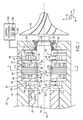
- FIG. 1 a partial cross-sectional side view of an embodiment of an electric machine system 10 (e.g., rotational electric machine) having an electromagnetic actuator 12 with a symmetrical structure is illustrated.
- an electric machine system 10 e.g., rotational electric machine
- the electromagnetic actuator 12 may be utilized as part of an AMB system to support a body 20 (e.g., rotor) of a rotational machine (e.g., electric machine system 10).
- the electromagnetic actuator 12 may be utilized in and/or with internal combustion engines (e.g., reciprocating combustion engines, gas turbines, etc.), steam turbines, pumps, turbochargers, compressors, electric motors, electrical generators, or any other type of rotational machine.
- the electric machine system 10 includes an electric motor 22 that drives an impeller 24 (e.g., liquid and/or gas impeller).
- the electric motor 22 may drive a turbine (e.g., turbine blades of a turbine stage).
- the electric machine system 12 includes the rotor 20, a stator 26, a shaft 28 (e.g., motor shaft) coupled to the rotor 20, and the impeller 24 mounted on and/or coupled to the shaft 28.
- a flow of fluid drives the impeller 24 (or turbine) causing the rotor 20 to spin circumferentially 18 about a rotational axis 30 via the shaft 28.
- the motor 22 converts mechanical energy into electrical energy and thus functions as a generator 22.
- the rotor 20 may be supported radially 16 and axially 14 without mechanical contact by one or more AMBs.
- a front AMB 32 provides both axial and radial suspension of a front end 34 of the rotor 20.
- the electric machine 10 includes one or more backup bearings 36 to support the rotor 20 when the AMB 32 is not being utilized.
- the rotor 20 rests on the backup bearing 36 when the AMB 32 is not utilized.
- the backup bearing 36 provides both axial and radial support to the rotor 20.
- a radial clearance between an inner diameter of the backup bearing 36 and an outer diameter of the rotor 20 portion interfacing with the bearing 36 enables the rotor 20 to be positioned radially 16 without touching the bearing 36 when the AMB 32 is activated.
- an axial clearance between the backup bearing 36 and the rotor 20 portion interfacing with the bearing 36 enables the rotor 20 to be positioned axially 14 without touching the bearing 36 when the AMB 32 is activated.
- the front AMB 32 includes the electromagnetic actuator 12.
- the electromagnetic actuator 12 is a combination radial and axial electromagnetic actuator that generates radial and axial electromagnetic forces to support the rotor 20 (e.g., with minimal contact or no contact) as it rotates about the rotational axis 30.
- the electromagnetic actuator 12 includes a mirrored or symmetrical structure (e.g., relative to a radial midplane of a radial pole assembly 42, the radial midplane being orthogonal to the rotational axis 30) that enables a balanced magnetic flux profile as described in greater detail below.
- the electromagnetic actuator 12 is homopolar (i.e., in the absence of radial loading, magnetic polarity remains the same circumferentially 18 around the rotor 20 at a specific axial position).
- the electromagnetic actuator 12 may be PM-biased as described in greater detail below.
- the electromagnetic actuator 12 may be EM-biased (e.g., using coils instead of permanent magnets).
- the electromagnetic actuator 12 includes a first axial pole assembly 38, a second axial pole assembly 40, and a radial pole assembly 42.
- the first axial pole assembly 38 includes a first axial pole 43, a second axial pole 44, an axial backiron 46, and an axial control coil 47 circumferentially 18 disposed about (but radially 16 offset from) the rotor 20.
- the axial poles 43, 44 and the axial backiron 46 may include an annular structure (e.g., annular plates).
- the axial backiron 46 is disposed (e.g., axially 14) between the axial poles 43, 44 coupling the axial poles 43, 44 magnetically.
- sides 48, 50 of the axial backiron 46 interface directly with side 52 of the first axial pole 43 and side 54 of the second axial pole 44, respectively.
- the axial control coil 47 is concentrically disposed within the axial backiron 46 and partially surrounded by or enclosed within the axial backiron 46 and the axial poles 43, 44.
- the axial poles 43, 44 and the axial backiron 46 may include or be composed of soft-magnetic materials (e.g., carbon steels and/or other soft magnetic material).
- the second axial pole assembly 40 is structurally identical to the first axial pole assembly 38.
- the second axial pole assembly 40 includes a first axial pole 56, a second axial pole 58, an axial backiron 60, and an axial control coil 62 circumferentially 18 disposed about (but radially 16 offset from) the rotor 20.
- the axial poles 56, 58 and the axial backiron 60 may include an annular structure (e.g., annular plates).
- the axial backiron 60 is disposed (e.g., axially 14) between the axial poles 56, 58 coupling the axial poles 56, 58.
- sides 64, 66 of the axial backiron 60 interface directly with side 68 of the first axial pole 56 and side 70 of the second axial pole 58, respectively.
- the axial control coil 62 is concentrically disposed within the axial backiron 60 and partially surrounded by or enclosed within the axial backiron 60 and the axial poles 56, 58.
- the axial coils 47, 62 include the same number of coils.
- the axial poles 56, 58 and the axial backiron 60 may include or be composed of soft-magnetic materials (e.g., carbon steels and/or other soft magnetic material).
- the radial pole assembly 42 is disposed (e.g., axially 14) between the axial pole assemblies 38, 40.
- the radial pole assembly 42 may include a plurality of radial control coils (see FIG. 3 ).
- the radial pole assembly 42 may include or be composed of soft-magnetic materials (e.g., carbon steels and/or other soft magnetic material).
- the radial pole assembly 42 may be assembled of magnetically permeable and electrically conductive laminations (e.g., steel and/or other magnetically permeable and electrically conductive laminations) stacked axially 14 and electrically isolated from each other. The electrical isolation may reduce eddy currents during energization of the radial pole assembly 42.
- the electromagnetic actuator 12 is PM-biased.
- the electromagnetic actuator 12 includes a first permanent magnet 72 disposed between the first axial pole assembly 38 and the radial pole assembly 42 and coupling the assemblies 38, 42.
- side 74 e.g., north pole side
- side 76 e.g., south pole side
- the electromagnetic actuator 12 also includes a second permanent magnet 82 disposed between the second axial pole assembly 40 and the radial pole assembly 42 and coupling the assemblies 40, 42.
- side 84 e.g., north pole side
- side 86 e.g., south pole side
- the permanent magnets 72, 82 each generate a magnetic bias flux that communicates with the first and second axial pole assemblies 38, 40, respectively, before combining in the radial pole assembly 42.
- the arrangement of the axial pole assemblies 38, 40, the radial pole assembly 42, and the permanent magnets 72, 82 provide the electromagnetic actuator 12 with a symmetrical or mirrored structure.
- the electromagnetic actuator 12 is structurally identical on both sides of the centerline. As discussed in greater detail below, the symmetrical structure of the electromagnetic actuator 12 enables a balanced magnetic flux profile.
- the electromagnetic actuator 12 is EM-biased.
- An EM-biased electromagnetic actuator utilizes coils instead of the permanent magnets 72, 82 to provide the bias flux.
- the electromagnetic actuator 12 when in operation, communicates a magnetic flux with actuator targets disposed on and/or integral to the rotor 20.
- a first axial actuator target 92 is disposed at a first axial position (e.g., adjacent the front end 34 of the rotor 20) along the rotor 20 and a second actuator target 94 is disposed at a second axial position (e.g., more proximal to the front end 34 of the rotor 20 relative to the axial position of the first axial actuator target 92) along the rotor 20.
- the first and second axial actuator targets 92, 94 may be integral to the rotor 20.
- the first axial actuator target is depicted as integrated with the rotor 20.
- the first and second actuator targets 92, 94 may be disposed on the rotor 20 (e.g., as depicted, the second actuator target 94 is disposed on the rotor 20).
- the first and second actuator targets 92, 94 may be fastened to the rotor 20 (e.g., via shrink-fitting or screwing the target 92, 94 on to the rotor 20).
- the first and second actuator targets 92, 94 may be annular in shape (e.g., annular collar). Both the first and second actuator targets 92, 94 extend circumferentially 18 about the rotor 20 and radially 16 away from a surface 100 of the rotor 20 (e.g., relative to the longitudinal axis 30).
- the actuator targets 92, 94 are solid pieces.
- the actuator targets 92, 94 may be assembled of magnetically permeable and electrically conductive laminations (e.g., steel and/or other magnetically permeable and electrically conductive laminations) stacked axially 14 and electrically isolated from each other (e.g., to reduce eddy currents).
- the first axial pole assembly 38 is disposed adjacent to the first axial actuator target 92.
- the axial pole assembly 38 partially surrounds or encloses the first axial actuator target 92.
- the first axial actuator target 92 includes end-facing surfaces 96, 98 that interface with side 52 of the first axial pole 43 and side 54 of the second axial pole 44 of the first axial pole assembly 38, respectively.
- the end-facing surface 96 of the target 92 and the side 52 of the axial pole 43 include an axial gap 102 (e.g., axial air gap) between them.
- the end-facing surface 98 of the target 92 and the side 54 of the axial pole 43 include an axial gap 104 (e.g., axial air gap) between them.
- the first axial pole assembly 38 communicates a magnetic flux across the gaps 102, 104 between the assembly 38 and the first axial actuator target 92.
- the first axial pole assembly 38 is magnetically coupled to and cooperates with the first axial actuator target 92 to define a first axial magnetic control circuit 106 (see FIG. 2 ) that generates an axial electromagnetic force to control axial movement of the rotor 20.
- the second axial pole assembly 40 is disposed adjacent to the second axial actuator target 94.
- the axial pole assembly 40 partially surrounds or encloses the second axial actuator target 94.
- the second axial actuator target 94 includes end-facing surfaces 108, 110 that interface with side 68 of the first axial pole 56 and side 70 of the second axial pole 58 of the second axial pole assembly 40, respectively.
- the end-facing surface 108 of the target 94 and the side 68 of the axial pole 56 include an axial gap 112 (e.g., axial air gap) between them.
- the end-facing surface 110 of the target 94 and the side 70 of the axial pole 58 include an axial gap 114 (e.g., axial air gap) between them.
- the second axial pole assembly 40 communicates a magnetic flux across the gaps 112, 114 between the assembly 40 and the second axial actuator target 94.
- the first axial pole assembly 40 is magnetically coupled to and cooperates with the first axial actuator target 94 to define a second axial magnetic control circuit 116 (see FIG. 2 ) that also generates an axial electromagnetic force to control axial movement of the rotor 20.
- a radial actuator target 118 is disposed at a third axial position along the rotor 20 between the first and second axial positions of the first and second axial actuator targets 92, 94, respectively.
- the radial actuator target 118 may include or be composed of soft-magnetic materials (e.g., carbon steels and/or other soft magnetic material).
- the radial actuator target 118 may be assembled of magnetically permeable and electrically conductive laminations (e.g., steel and/or other magnetically permeable and electrically conductive laminations) stacked axially 14 and electrically isolated from each other (e.g., to reduce eddy currents).
- the radial actuator target includes an annular cylindrical shape.
- the radial pole assembly 42 is disposed adjacent to a lateral surface 120 of the radial actuator target 118.
- the radial pole assembly 42 and the lateral surface of the radial actuator target 118 include a radial gap 122 (e.g., radial air gap) between them.
- the radial pole assembly 42 communicates a magnetic flux across the gap 122 between the assembly 42 and the radial actuator target 118.
- the radial pole assembly 42 also communicates a magnetic flux with the first and second axial pole assemblies 38, 40.
- the radial pole assembly 42 is magnetically coupled to and cooperates with the radial actuator target 118 to define a radial magnetic control circuit 123 that generates a radial electromagnetic force to control radial movement of the rotor 20.
- the first axial actuator target 92, the second axial actuator target 94, and the radial actuator target 118 are magnetically coupled to each other as well as the rotor 20 as described in greater detail below.
- the first and second actuator targets 92, 94, the first and second axial pole assemblies 38, 40, the radial actuator target 118, and the radial pole assembly 42 define a magnetic bias circuit 124 (see FIG. 2 ) as described in greater detail below.
- the first axial magnetic control circuit 106 is magnetically coupled to and cooperates with the radial pole assembly 42 to define a first coupled magnetic circuit 126 (see FIG. 2 ).
- the first coupled magnetic circuit 126 generates a first coupled flux (e.g., axial couple flux).
- the second axial magnetic control circuit 116 is magnetically coupled to and cooperates with the radial pole assembly 42 to define a second coupled magnetic circuit 128 (see FIG. 2 ).
- the second coupled magnetic circuit 128 generates a second coupled flux (e.g., axial couple flux).
- the axial pole assemblies 38, 40 are similar or identical (e.g., the axial control coils 47, 62 include the same number of turns).
- the coupled fluxes will have the same amplitude but opposite directions as described in greater detail below.
- the first coupled magnetic flux may be generated radially 16 in one direction between the radial pole assembly 42 and the radial actuator target 118, while the second coupled magnetic flux may be generated radially 16 in the opposite direction between the assembly 42 and the target 118.
- the coupled magnetic fluxes cancel each other out resulting in a balanced magnetic flux profile for the electromagnetic actuator 12 during operation.
- the cancelation of the coupled magnetic fluxes keeps the axial control forces and the radial control forces (as well as the control circuits 106, 116, 123) from cross-coupling.
- the balanced magnetic flux profile means the electromagnetic actuator 12 does not need compensating coils, thus, simplifying the calibration process and reducing the components needed for the electromagnetic actuator 12.
- the electromagnetic actuator 12 is more robust (e.g., minimizing performance degradation over time) and may increase axial force capability and load capacity.
- the electric machine 10 includes a controller or control electronics 130 that produces control currents that are provided to the corresponding control coils of the axial pole assemblies 38, 40 and the radial pole assembly 42.
- the control currents energize the control coils resulting in the generation of electromagnetic forces that will move the rotor 20.
- the controlled electromagnetic forces support the moving rotor 20 with minimal contact or no contact to provide frictionless or nearly frictionless movement of the rotor 20 in both axial 14 and radial 16 directions.
- the control coils correspond to different axes that will generate electromagnetic forces to move the rotor 20 along the respective axes upon being energized. For example, the axial control coils 47, 62 upon being energized will move the rotor 20 axially 14, while the radial control coils (see FIG.
- control electronics 130 may include one or more power amplifiers that convert control voltages generated by control electronics 130 into respective control currents provided to the control coils. Since the axial control coils 47, 62 are the same, in certain embodiments, a single power amplifier may be used for both coils 47, 62. In certain embodiments, different power amplifiers may be used for the coils 47, 62 (e.g., if the axial gaps with respect to the axial pole assemblies 38, 40 vary).
- the electric machine 10 also includes sensors in communication with the control electronics 130.
- non-contact position sensors such as radial position sensors 132 and axial position sensors 134, may be utilized to determine the radial and axial positions, respectively, of the rotor 20 (e.g., front end 34 of the rotor 20) in space.
- the sensors 132, 134 are depicted adjacent the front end 34 of the rotor 20, the sensors 132, 134 may be disposed at different positions (e.g., axial positions) relative to the rotor 20.
- the radial position sensors 132 may be disposed on either side 80, 90 of the radial pole assembly 42.
- the sensor 132, 134 provide sensor voltages representative of the position of the rotor 20 to the control electronics 130, which may be used by the control electronics 130 to adjust the electromagnetic forces applied by the electromagnetic actuator 12 to the rotor 20 to control the rotor's position.
- the control electronics 130 may include processing circuitry (e.g., processor 136) and/or memory circuitry (e.g., memory 138).
- the processor 136 may execute instructions to control the operation of the electromagnetic actuator 12 and the positioning of the rotor 20. These instructions may be encoded in programs or code stored in a tangible non-transitory computer-readable medium (e.g., an optical disc, solid state device, chip, firmware) such as the memory 138.
- the memory 138 may store reference voltages representative of a particular position (e.g., axially and radially) of the rotor 20.
- the processor 136 may compare the sensor voltage received from the sensors 132, 134 to the references voltages to adjust the control currents applied to the control coils and thus, the position of the rotor 20, if needed.
- the actuator coils e.g., axial and radial control coils
- FIG. 2 is a cross-sectional side view of the electromagnetic actuator 12 of FIG. 1 and a portion of the body 20 (e.g., rotor).
- the electromagnetic actuator 12 and its targets 92, 94, 118 are as described above.
- the first permanent magnet 72 generates magnetic bias flux 140 that splits into two portions 140A, 140B within the first axial pole assembly 38. Specifically, portion 140A is directed along the axial pole 44 to the axial pole 43, via the axial backiron 46, and then from the axial pole 43 across the axial gap 102 (e.g., axially 14) to the first axial actuator target 92.
- Portion 140B is directed along the axial pole 44 and then across axial gap 104 (e.g., axially 14) to the first axial actuator target 92.
- the two portions 140A, 140B of the magnetic bias flux 140 merge together again within the first axial actuator target 92 and are directed within the soft magnetic body 20 axially 14 towards the radial actuator target 118.
- the second permanent magnet 72 generates magnetic bias flux 142 that splits into two portions 142A, 142B within the second axial pole assembly 40.
- portion 142A is directed along the axial pole 56 to the axial pole 58, via the axial backiron 60, and then from the axial pole 58 across the axial gap 114 (e.g., axially 14) to the second axial actuator target 94.
- Portion 142B is directed along the axial pole 56 and then across axial gap 112 (e.g., axially 14) to the second axial actuator target 94.
- the two portions 142A, 142B of the magnetic bias flux 142 merge together again within the second axial actuator target 94 and are directed within the soft magnetic body 20 axially 14 towards the radial actuator target 118.
- the magnetic bias fluxes 140, 142 merge together within the radial actuator target 118 to form a combined magnetic bias flux 144 that is directed (e.g., radially 16) across the radial gap 122 to the radial pole assembly 42 to close the magnetic bias flux loop formed by the magnetic bias fluxes 140, 142 generated by the permanent magnets 72, 82.
- the magnetic bias flux loop defines the magnetic bias circuit 124.
- Axial force 145 (e.g., axial electromagnetic force), F AX , is generated by energizing the axial control coils 47, 62 with a respective axial control current 146, 148 that flows through the coils 47, 62 circumferentially 18 about the axis 30.
- the axial control current 146 produces magnetic axial control flux 150 (shown as dotted lines) that propagates through the axial poles 43, 44, the axial backiron 46, the axial gaps 102, 104, and the axial actuator target 92 to define the axial magnetic control circuit 106.
- the axial control current 148 produces magnetic axial control flux 152 (shown as dotted lines) that propagates through the axial poles 56, 58, the axial backiron 60, the axial gaps 112, 114, and the second axial actuator target 94 to define the axial magnetic control circuit 116.
- the magnitude and direction of the magnetic axial control fluxes 150, 152 can be changed by changing the currents 146, 148.
- the bias flux 140 in axial gaps 102, 104 may be equal or near equal
- the bias flux 142 in the axial gaps 112, 114 may be equal or near equal
- the net axial electromagnetic force acting on each of the axial actuator targets 92, 94 may be a zero or near zero net value.
- the magnetic axial control fluxes 150, 152 are not zero, the magnetic axial control fluxes 150, 152 respectively add to the bias fluxes 140A, 142B in the respective axial gaps 102, 112, but respectively subtract from the bias fluxes 140B, 142A in the respective axial gaps 104, 114.
- the differences in flux densities acting on the end-facing surfaces 96, 98 of the first axial actuator target 92 and the end-facing surfaces 108, 110 of the second axial actuator target 94 result in the axial force 145, F AX , along the axial axis 14 in the direction indicated (e.g., towards the axial poles 43, 56).
- the first axial pole assembly 38 (including the axial magnetic control circuit 106) and the radial pole assembly 42 are coupled via axial couple flux 154 (shown as hashed lines) that enters the axial control flux 150 (i.e., axial magnetic control circuit 106).
- the axial couple flux 154 is directed from the first axial actuator target 92 axially 14 towards the radial actuator target 118, across the radial gap 122 to the radial pole assembly 42 radially 16 (e.g., away from the axis 30), and then axially 14 across the permanent magnet 72 to the axial pole assembly 38 and the axial magnetic control circuit 106 to define the coupled magnetic circuit 126.
- the second axial pole assembly 40 (including the axial magnetic control circuit 116) and the radial pole assembly 42 are coupled via axial couple flux 156 (shown as hashed lines) that enters the axial control flux 152 (i.e., axial magnetic control circuit 116).
- the axial couple flux 156 is directed from the second axial pole assembly 40 via the permanent magnet 82 to the radial pole assembly 42, along the radial pole assembly 42 radially 16 (e.g., toward the axis 30), across the radial gap 122 to the radial actuator target 118, from the radial actuator target 118 axially 14 towards the second actuator target 94, and then into the axial magnetic control circuit 116 to define the coupled magnetic circuit 128.
- the axial couple fluxes 154, 156 flow in opposite radial directions (e.g., different phases) with equal amplitude (e.g., assuming the same number of turns in each axial control coil 47, 62) along the radial pole assembly 42, the axial couple fluxes cancel out and no cross-coupling occurs between axial and radial control forces.
- the balanced magnetic flux profile means the electromagnetic actuator 12 does not need compensating coils, thus, simplifying the calibration process and reducing the components needed for the electromagnetic actuator 12.
- the electromagnetic actuator 12 is more robust (e.g., minimizing performance degradation over time) and may increase axial force capability (e.g., given a maximum shaft diameter limitation) and load capacity.
- the radial pole assembly 42 includes a plurality of radial control coils.
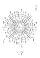
- FIG. 3 is an axial cross-sectional view of the electromagnetic actuator 12 of FIG. 1 and the body 20, taken along line 3-3 of FIG. 1 .
- the radial pole assembly 42 includes a plurality of radial control poles 158.
- the radial pole assembly 42 may include at least three radial control poles 158.
- the radial pole assembly 42 includes fours radial control poles 158A-158D.
- Radial force 159 (e.g., radial electromagnetic force), F R , is generated by energizing the radial control poles 158.
- Radial control windings or coils 160 wrap around the poles 158 in slots 162 disposed between the poles 158. As depicted, control windings 160A-D are respectively wrapped around poles 158A-D.
- the combined bias flux 144 generated by the permanent magnets 72, 82 flows radially 16 through the radial air gaps 122A-D and within the radial control poles 158A-D.
- the bias flux density for each pole 158A-D associated with respective windings 160A-D is the same or similar due to symmetry of the system.
- the net radial force 159, F R may be at or near zero.
- Energizing the radial control coils 160A-D alters the flux distribution resulting in the generation of a non-zero radial force 159.
- energizing control coils 160A, 160C with radial control currents 164A, 164C, respectively, produces radial control flux 166.
- the control flux 166 adds to the bias flux 144 in the air gap 122A under the pole 158A and subtracts from the bias flux 144 in the air gap 122C under the pole 158C.
- the radial force 159 acting on the target is directed upwards in direction 172.
- a radial force can be produced in direction 174. Reversing the direction of the radial control currents 164A, 164C in the coils 160A, 160C generate a radial force in direction 176. Also, reversing the direction of the radial control currents 164B, 164D in the coils 160B, 160D generates a radial force in direction 178.
- the radial control forces and the axial control forces are not cross-coupled.
- the axial couple fluxes 154, 156 may not contribute to any differences in flux densities acting on the lateral surface 120 on the radial actuator target 118 that generate a radial force to control movement of the body 20.
- embodiments include providing systems and methods for utilizing the electromagnetic actuator 12 having a balanced magnetic flux profile.
- embodiments include the electromagnetic actuator 12 having a symmetrical structure.
- the axial pole assemblies 38, 40 are symmetrical relative to the radial pole assembly 42.
- axial couple fluxes 154, 156 cancel each other out.
- cross-coupling does not occur between axial control forces and radial control forces.
- the balanced magnetic flux profile means the electromagnetic actuator 12 does not need compensating coils, thus, simplifying the calibration process and reducing the components needed for the electromagnetic actuator 12.
- the electromagnetic actuator 12 is more robust (e.g., minimizing performance degradation over time) and may increase axial capability and load capacity.
Landscapes
- Engineering & Computer Science (AREA)
- General Engineering & Computer Science (AREA)
- Mechanical Engineering (AREA)
- Physics & Mathematics (AREA)
- Electromagnetism (AREA)
- Magnetic Bearings And Hydrostatic Bearings (AREA)
- Reciprocating, Oscillating Or Vibrating Motors (AREA)
- Power Engineering (AREA)
- Connection Of Motors, Electrical Generators, Mechanical Devices, And The Like (AREA)
Applications Claiming Priority (1)
| Application Number | Priority Date | Filing Date | Title |
|---|---|---|---|
| US14/279,505 US20150330444A1 (en) | 2014-05-16 | 2014-05-16 | Symmetrical electromagnetic actuator |
Publications (2)
| Publication Number | Publication Date |
|---|---|
| EP2945173A2 true EP2945173A2 (de) | 2015-11-18 |
| EP2945173A3 EP2945173A3 (de) | 2015-12-09 |
Family
ID=53385455
Family Applications (1)
| Application Number | Title | Priority Date | Filing Date |
|---|---|---|---|
| EP15167732.5A Withdrawn EP2945173A3 (de) | 2014-05-16 | 2015-05-14 | Symmetrischer elektromagnetischer aktuator |
Country Status (4)
| Country | Link |
|---|---|
| US (1) | US20150330444A1 (de) |
| EP (1) | EP2945173A3 (de) |
| JP (1) | JP2015220982A (de) |
| KR (1) | KR20150132001A (de) |
Cited By (1)
| Publication number | Priority date | Publication date | Assignee | Title |
|---|---|---|---|---|
| US10767691B2 (en) | 2015-02-26 | 2020-09-08 | Carrier Corporation | Magnetic bearing |
Families Citing this family (9)
| Publication number | Priority date | Publication date | Assignee | Title |
|---|---|---|---|---|
| US10927892B2 (en) * | 2015-02-26 | 2021-02-23 | Carrier Corporation | Magnetic thrust bearing |
| JP6590070B2 (ja) * | 2016-08-12 | 2019-10-16 | 株式会社Soken | 電動モータシステム |
| EP3507514B1 (de) * | 2016-08-31 | 2020-12-23 | Carrier Corporation | Magnetisches axiallager |
| EP3607218B1 (de) | 2017-04-01 | 2021-10-20 | Carrier Corporation | Magnetisches radiallager mit flussverstärkung |
| CN110462234B (zh) | 2017-04-01 | 2022-05-31 | 开利公司 | 具有磁通升高的磁径向轴承、使用磁轴承的方法以及机器 |
| WO2018182891A1 (en) | 2017-04-01 | 2018-10-04 | Carrier Corporation | Magnetic radial bearing with flux boost |
| US10947986B2 (en) * | 2018-07-11 | 2021-03-16 | Ch Biomedical (Usa) Inc. | Compact centrifugal pump with magnetically suspended impeller |
| US11441485B2 (en) * | 2019-03-20 | 2022-09-13 | Raytheon Technologies Corporation | Electric motor control for demand fuel pumping system |
| CN115949672B (zh) * | 2022-12-07 | 2026-01-30 | 珠海格力电器股份有限公司 | 一种磁悬浮轴承和磁悬浮轴承系统 |
Citations (1)
| Publication number | Priority date | Publication date | Assignee | Title |
|---|---|---|---|---|
| WO2015074855A1 (en) * | 2013-11-22 | 2015-05-28 | Nuovo Pignone Srl | Motor-compressor with stage impellers integrated in the motor-rotors |
Family Cites Families (10)
| Publication number | Priority date | Publication date | Assignee | Title |
|---|---|---|---|---|
| US3937533A (en) * | 1974-02-08 | 1976-02-10 | The United States Of America As Represented By The United States National Aeronautics And Space Administration Office Of General Counsel-Code Gp | Axially and radially controllable magnetic bearing |
| US4077678A (en) * | 1976-07-30 | 1978-03-07 | The United States Of America As Represented By The Administrator Of The National Aeronautics And Space Administration | Energy storage apparatus |
| FR2756335B1 (fr) * | 1996-11-25 | 1999-02-12 | Aerospatiale | Palier magnetique actif longitudinalement et transversalement |
| JPH11101235A (ja) * | 1997-07-30 | 1999-04-13 | Nippon Seiko Kk | 磁気軸受 |
| US6359357B1 (en) * | 2000-08-18 | 2002-03-19 | The United States Of America As Represented By The Administrator Of The National Aeronautics And Space Administration | Combination radial and thrust magnetic bearing |
| JP2004293598A (ja) * | 2003-03-26 | 2004-10-21 | Koyo Seiko Co Ltd | 磁気軸受装置 |
| JP2009014084A (ja) * | 2007-07-03 | 2009-01-22 | Jtekt Corp | 軸受装置およびこれを備えた遠心圧縮機 |
| EP2209186B1 (de) * | 2007-10-18 | 2020-05-27 | Iwaki Co., Ltd. | Magnetisch aufgehängte(r) motor und pumpe |
| CN102305242B (zh) * | 2011-08-15 | 2013-03-13 | 江苏大学 | 一种径向-轴向三自由度交直流混合磁轴承 |
| CN203140787U (zh) * | 2012-11-21 | 2013-08-21 | 江苏大学 | 一种五自由度数控机床高速磁悬浮电主轴 |
-
2014
- 2014-05-16 US US14/279,505 patent/US20150330444A1/en not_active Abandoned
-
2015
- 2015-05-11 JP JP2015096137A patent/JP2015220982A/ja active Pending
- 2015-05-14 EP EP15167732.5A patent/EP2945173A3/de not_active Withdrawn
- 2015-05-14 KR KR1020150067344A patent/KR20150132001A/ko not_active Ceased
Patent Citations (1)
| Publication number | Priority date | Publication date | Assignee | Title |
|---|---|---|---|---|
| WO2015074855A1 (en) * | 2013-11-22 | 2015-05-28 | Nuovo Pignone Srl | Motor-compressor with stage impellers integrated in the motor-rotors |
Cited By (2)
| Publication number | Priority date | Publication date | Assignee | Title |
|---|---|---|---|---|
| US10767691B2 (en) | 2015-02-26 | 2020-09-08 | Carrier Corporation | Magnetic bearing |
| EP3262310B1 (de) * | 2015-02-26 | 2020-10-28 | Carrier Corporation | Magnetlager |
Also Published As
| Publication number | Publication date |
|---|---|
| EP2945173A3 (de) | 2015-12-09 |
| KR20150132001A (ko) | 2015-11-25 |
| US20150330444A1 (en) | 2015-11-19 |
| JP2015220982A (ja) | 2015-12-07 |
Similar Documents
| Publication | Publication Date | Title |
|---|---|---|
| US20150330444A1 (en) | Symmetrical electromagnetic actuator | |
| US8796894B2 (en) | Combination radial/axial electromagnetic actuator | |
| US8482174B2 (en) | Electromagnetic actuator | |
| EP3670946B1 (de) | Magnetschwebelager, magnetschweberotorträgeranordnung und verdichter | |
| US10177627B2 (en) | Homopolar, flux-biased hysteresis bearingless motor | |
| CA2894788C (en) | Permanent magnet machine with segmented sleeve for magnets | |
| US5767597A (en) | Electromagnetically biased homopolar magnetic bearing | |
| US8847451B2 (en) | Combination radial/axial electromagnetic actuator with an improved axial frequency response | |
| US11333196B2 (en) | Thrust active magnetic bearing for shaft slow roll control | |
| US20120306305A1 (en) | Arrangement of axial and radial electromagnetic actuators | |
| CN104201935A (zh) | 一种四自由度磁悬浮飞轮 | |
| WO2009093428A1 (ja) | ベアリングレスモータ | |
| CN104118579B (zh) | 一种四自由度单框架磁悬浮控制力矩陀螺 | |
| CN102303709B (zh) | 一种大力矩磁悬浮飞轮 | |
| CN102434587A (zh) | 具有被动阻尼作用的永磁被动式轴向磁悬浮轴承 | |
| JP2017106899A (ja) | 回転子シャフトの軸線方向位置を検出するためのデバイスならびに回転機械に対してのそれの応用 | |
| JP3850195B2 (ja) | 磁気浮上モータ | |
| Eryong et al. | A novel structure for low-loss radial hybrid magnetic bearing | |
| CN104145126B (zh) | 具有力补偿的磁性轴承 | |
| US20140265689A1 (en) | Generating radial electromagnetic forces | |
| Kurita et al. | Analysis and design of a bearingless axial-force/torque motor with flex-PCB windings | |
| EP3507514B1 (de) | Magnetisches axiallager | |
| Yang et al. | Design of a thrust actuator for magnetic bearings with low radial attraction force | |
| US10927892B2 (en) | Magnetic thrust bearing | |
| US8110955B2 (en) | Magnetic bearing device of a rotor shaft against a stator with rotor disc elements, which engage inside one another, and stator disc elements |
Legal Events
| Date | Code | Title | Description |
|---|---|---|---|
| PUAL | Search report despatched |
Free format text: ORIGINAL CODE: 0009013 |
|
| PUAI | Public reference made under article 153(3) epc to a published international application that has entered the european phase |
Free format text: ORIGINAL CODE: 0009012 |
|
| AK | Designated contracting states |
Kind code of ref document: A2 Designated state(s): AL AT BE BG CH CY CZ DE DK EE ES FI FR GB GR HR HU IE IS IT LI LT LU LV MC MK MT NL NO PL PT RO RS SE SI SK SM TR |
|
| AX | Request for extension of the european patent |
Extension state: BA ME |
|
| AK | Designated contracting states |
Kind code of ref document: A3 Designated state(s): AL AT BE BG CH CY CZ DE DK EE ES FI FR GB GR HR HU IE IS IT LI LT LU LV MC MK MT NL NO PL PT RO RS SE SI SK SM TR |
|
| AX | Request for extension of the european patent |
Extension state: BA ME |
|
| RIC1 | Information provided on ipc code assigned before grant |
Ipc: F04D 29/00 20060101AFI20151030BHEP Ipc: F16C 32/04 20060101ALI20151030BHEP |
|
| 17P | Request for examination filed |
Effective date: 20160609 |
|
| RBV | Designated contracting states (corrected) |
Designated state(s): AL AT BE BG CH CY CZ DE DK EE ES FI FR GB GR HR HU IE IS IT LI LT LU LV MC MK MT NL NO PL PT RO RS SE SI SK SM TR |
|
| RIN1 | Information on inventor provided before grant (corrected) |
Inventor name: WANG, ZHIYANG |
|
| 17Q | First examination report despatched |
Effective date: 20160718 |
|
| STAA | Information on the status of an ep patent application or granted ep patent |
Free format text: STATUS: THE APPLICATION IS DEEMED TO BE WITHDRAWN |
|
| 18D | Application deemed to be withdrawn |
Effective date: 20171201 |