EP2945199B1 - Supraleitender fehlerstrombegrenzer und kühlverfahren für ein supraleitendes element in dem supraleitenden fehlerstrombegrenzer - Google Patents
Supraleitender fehlerstrombegrenzer und kühlverfahren für ein supraleitendes element in dem supraleitenden fehlerstrombegrenzer Download PDFInfo
- Publication number
- EP2945199B1 EP2945199B1 EP14751627.2A EP14751627A EP2945199B1 EP 2945199 B1 EP2945199 B1 EP 2945199B1 EP 14751627 A EP14751627 A EP 14751627A EP 2945199 B1 EP2945199 B1 EP 2945199B1
- Authority
- EP
- European Patent Office
- Prior art keywords
- superconducting
- elements
- superconducting elements
- fault current
- disposed
- Prior art date
- Legal status (The legal status is an assumption and is not a legal conclusion. Google has not performed a legal analysis and makes no representation as to the accuracy of the status listed.)
- Not-in-force
Links
- 238000001816 cooling Methods 0.000 title claims description 110
- 239000002826 coolant Substances 0.000 claims description 123
- 239000007788 liquid Substances 0.000 claims description 80
- 238000009835 boiling Methods 0.000 claims description 38
- 230000008859 change Effects 0.000 claims description 17
- IJGRMHOSHXDMSA-UHFFFAOYSA-N Atomic nitrogen Chemical compound N#N IJGRMHOSHXDMSA-UHFFFAOYSA-N 0.000 description 63
- 239000010408 film Substances 0.000 description 33
- 229910001873 dinitrogen Inorganic materials 0.000 description 21
- 229910052757 nitrogen Inorganic materials 0.000 description 21
- 239000007789 gas Substances 0.000 description 19
- 230000000670 limiting effect Effects 0.000 description 19
- 238000011084 recovery Methods 0.000 description 19
- 239000002887 superconductor Substances 0.000 description 18
- 230000006872 improvement Effects 0.000 description 14
- 239000004065 semiconductor Substances 0.000 description 14
- 238000005192 partition Methods 0.000 description 10
- 230000002829 reductive effect Effects 0.000 description 10
- 230000001939 inductive effect Effects 0.000 description 9
- 239000000463 material Substances 0.000 description 9
- 238000009792 diffusion process Methods 0.000 description 7
- 230000000630 rising effect Effects 0.000 description 7
- 230000003247 decreasing effect Effects 0.000 description 6
- 239000004020 conductor Substances 0.000 description 5
- 230000000694 effects Effects 0.000 description 3
- 238000010438 heat treatment Methods 0.000 description 3
- 229910052751 metal Inorganic materials 0.000 description 3
- 239000002184 metal Substances 0.000 description 3
- 238000000034 method Methods 0.000 description 3
- 230000009467 reduction Effects 0.000 description 3
- 239000000126 substance Substances 0.000 description 3
- 229920002430 Fibre-reinforced plastic Polymers 0.000 description 2
- 230000000052 comparative effect Effects 0.000 description 2
- 230000007423 decrease Effects 0.000 description 2
- 230000006866 deterioration Effects 0.000 description 2
- 239000011151 fibre-reinforced plastic Substances 0.000 description 2
- 238000009413 insulation Methods 0.000 description 2
- 230000008569 process Effects 0.000 description 2
- 238000005057 refrigeration Methods 0.000 description 2
- 230000001172 regenerating effect Effects 0.000 description 2
- 230000000452 restraining effect Effects 0.000 description 2
- 238000004088 simulation Methods 0.000 description 2
- 239000000758 substrate Substances 0.000 description 2
- 239000010409 thin film Substances 0.000 description 2
- QVGXLLKOCUKJST-UHFFFAOYSA-N atomic oxygen Chemical compound [O] QVGXLLKOCUKJST-UHFFFAOYSA-N 0.000 description 1
- 229910052797 bismuth Inorganic materials 0.000 description 1
- JCXGWMGPZLAOME-UHFFFAOYSA-N bismuth atom Chemical compound [Bi] JCXGWMGPZLAOME-UHFFFAOYSA-N 0.000 description 1
- 230000010485 coping Effects 0.000 description 1
- 238000006073 displacement reaction Methods 0.000 description 1
- 230000002708 enhancing effect Effects 0.000 description 1
- -1 for example Substances 0.000 description 1
- 230000005484 gravity Effects 0.000 description 1
- 239000001307 helium Substances 0.000 description 1
- 229910052734 helium Inorganic materials 0.000 description 1
- SWQJXJOGLNCZEY-UHFFFAOYSA-N helium atom Chemical compound [He] SWQJXJOGLNCZEY-UHFFFAOYSA-N 0.000 description 1
- 239000012774 insulation material Substances 0.000 description 1
- 238000012423 maintenance Methods 0.000 description 1
- 239000011159 matrix material Substances 0.000 description 1
- 230000007246 mechanism Effects 0.000 description 1
- 239000001301 oxygen Substances 0.000 description 1
- 229910052760 oxygen Inorganic materials 0.000 description 1
- 230000037361 pathway Effects 0.000 description 1
- 229920006267 polyester film Polymers 0.000 description 1
- 230000005855 radiation Effects 0.000 description 1
- 229910052761 rare earth metal Inorganic materials 0.000 description 1
- 230000003252 repetitive effect Effects 0.000 description 1
- 230000002441 reversible effect Effects 0.000 description 1
- 229910001220 stainless steel Inorganic materials 0.000 description 1
- 239000010935 stainless steel Substances 0.000 description 1
- 238000004804 winding Methods 0.000 description 1
- 229910052727 yttrium Inorganic materials 0.000 description 1
- VWQVUPCCIRVNHF-UHFFFAOYSA-N yttrium atom Chemical compound [Y] VWQVUPCCIRVNHF-UHFFFAOYSA-N 0.000 description 1
- 229910021521 yttrium barium copper oxide Inorganic materials 0.000 description 1
Images










Classifications
-
- H—ELECTRICITY
- H05—ELECTRIC TECHNIQUES NOT OTHERWISE PROVIDED FOR
- H05K—PRINTED CIRCUITS; CASINGS OR CONSTRUCTIONAL DETAILS OF ELECTRIC APPARATUS; MANUFACTURE OF ASSEMBLAGES OF ELECTRICAL COMPONENTS
- H05K7/00—Constructional details common to different types of electric apparatus
- H05K7/20—Modifications to facilitate cooling, ventilating, or heating
- H05K7/20218—Modifications to facilitate cooling, ventilating, or heating using a liquid coolant without phase change in electronic enclosures
- H05K7/20236—Modifications to facilitate cooling, ventilating, or heating using a liquid coolant without phase change in electronic enclosures by immersion
-
- H—ELECTRICITY
- H02—GENERATION; CONVERSION OR DISTRIBUTION OF ELECTRIC POWER
- H02H—EMERGENCY PROTECTIVE CIRCUIT ARRANGEMENTS
- H02H7/00—Emergency protective circuit arrangements specially adapted for specific types of electric machines or apparatus or for sectionalised protection of cable or line systems, and effecting automatic switching in the event of an undesired change from normal working conditions
- H02H7/001—Emergency protective circuit arrangements specially adapted for specific types of electric machines or apparatus or for sectionalised protection of cable or line systems, and effecting automatic switching in the event of an undesired change from normal working conditions for superconducting apparatus, e.g. coils, lines, machines
-
- H—ELECTRICITY
- H02—GENERATION; CONVERSION OR DISTRIBUTION OF ELECTRIC POWER
- H02H—EMERGENCY PROTECTIVE CIRCUIT ARRANGEMENTS
- H02H9/00—Emergency protective circuit arrangements for limiting excess current or voltage without disconnection
- H02H9/02—Emergency protective circuit arrangements for limiting excess current or voltage without disconnection responsive to excess current
- H02H9/023—Current limitation using superconducting elements
-
- H—ELECTRICITY
- H10—SEMICONDUCTOR DEVICES; ELECTRIC SOLID-STATE DEVICES NOT OTHERWISE PROVIDED FOR
- H10N—ELECTRIC SOLID-STATE DEVICES NOT OTHERWISE PROVIDED FOR
- H10N60/00—Superconducting devices
- H10N60/30—Devices switchable between superconducting and normal states
-
- Y—GENERAL TAGGING OF NEW TECHNOLOGICAL DEVELOPMENTS; GENERAL TAGGING OF CROSS-SECTIONAL TECHNOLOGIES SPANNING OVER SEVERAL SECTIONS OF THE IPC; TECHNICAL SUBJECTS COVERED BY FORMER USPC CROSS-REFERENCE ART COLLECTIONS [XRACs] AND DIGESTS
- Y02—TECHNOLOGIES OR APPLICATIONS FOR MITIGATION OR ADAPTATION AGAINST CLIMATE CHANGE
- Y02E—REDUCTION OF GREENHOUSE GAS [GHG] EMISSIONS, RELATED TO ENERGY GENERATION, TRANSMISSION OR DISTRIBUTION
- Y02E40/00—Technologies for an efficient electrical power generation, transmission or distribution
- Y02E40/60—Superconducting electric elements or equipment; Power systems integrating superconducting elements or equipment
Definitions
- the present invention relates to a superconducting fault current limiter and a cooling method for a superconducting element within superconducting fault current limiter.
- a fault current limiter is a device that is installed in an electric power system or the like.
- An installed fault current limiter can reduce a fault current caused by a short circuit or the like so as to reduce damage on a device connected thereto.
- the superconducting element used in such fault current limiters is cooled by being immersed in a liquid coolant such as liquid helium and liquid nitrogen in order to maintain an ultralow temperature condition.
- a liquid coolant such as liquid helium and liquid nitrogen
- the superconducting element changes to a normal conducting state, and the element temperature is drastically increased.
- a fault current limiter is used generally along with a fault current breaker. In the event of a fault current, it is required to reduce the fault current until the breaker works (approximately 0.1 [s]). Unless the superconducting element is cooled immediately once the breaker cuts off the fault current, the element life is largely decreased, which eventually decrease the life of the fault current limiter.
- a superconducting element with the lowest critical current tends to generate a heat for the longest time and to have a shorter life than the other superconducting elements.
- the life of the overall device is decreased to a great extent.
- Patent Document 1 discloses a cooling structure that includes a coolant vessel that accommodates a semiconductor element as a heat source and a liquid coolant, a partition wall that divides the inner space of the coolant vessel into a coolant supplying area and an element disposed area, a coolant jetting port that is a nozzle extending from the partition wall toward the semiconductor element, and a disturbance forming member that disturbs the flow of the coolant near the outlet of the coolant jetting port.
- the liquid coolant is jetted from the coolant jetting port toward the semiconductor element by using supplying pressure of the coolant, and the disturbance forming member disturbs the flow of the coolant so that nucleate boiling occurs on the overall flat surface of the semiconductor element as uniformly as possible.
- Patent Document 2 discloses a cooling structure that includes a coolant vessel that accommodates a semiconductor element as a heat source and a liquid coolant, a cooling pipe disposed between the inner and outer walls of the coolant vessel, and a plurality of protrusions that extend from the inner wall of the coolant vessel toward the semiconductor element so as to trap bubbles.
- the protrusions capture bubbles of the coolant that are produced due to the increased temperature of the semiconductor element, so as to proactively cool down the bubbles. With this, high cooling efficiency is achieved.
- Patent Document 3 discloses a cooling device that includes a coolant vessel that houses a semiconductor element and liquid coolant, and a cooling fin disposed on the outer wall of the coolant vessel.
- the semiconductor element is disposed on the inner bottom of the coolant vessel, and a flow path heading right above from the semiconductor element and a flow path that returns the coolant to the bottom around the semiconductor element are formed.
- the liquid coolant heated by the semiconductor element rises along the center flow path and is then cooled by the cooling fin when it flows down along the outer flow path. With this circulation, improved cooling efficiency is achieved.
- Patent Document 4 discloses providing a coolant vessel that accommodates a liquid coolant and a superconducting device as a component to be cooled, a partition plate that surrounds the superconducting device in the coolant vessel, a heat exchanger that independently cools the inner area and the outer area of the partition plate.
- the coolant is cooled such that the inner area of the partition plate is cooler than the outer area, so that the coolant flows down in the inner side of the partition plate and flows up in the outer side of the partition plate.
- Patent Document 1 is intended to cool the semiconductor element that undergoes a rather moderate temperature rise. Accordingly, it is envisioned that only nucleate boiling occurs on the surface of the element.
- Patent Document 1 requires the specially structured cooling vessel provided with the partition wall disposed therein, the coolant jetting port formed in the partition wall and the like. This causes problems such as the complicated overall structure and an increased cost for the device.
- Patent Document 2 requires a specially structured cooling vessel provided with the cooling pipe disposed between the inner and outer walls, the protrusions on the inner wall and the like. This causes problems such as the complicated overall structure and an increased cost for the device.
- the component to be cooled is a semiconductor element, it is intended to cool it only to ambient temperature, and the cooling fin disposed on the outer side of the coolant vessel bears the cooling of the liquid coolant.
- a superconducting fault current limiter requires to cool its superconducting element to an ultralow temperature. Further, in the event of a fault current, the superconducting element causes severe film boiling in the liquid coolant. Therefore, it is difficult for the cooling device with such cooling efficiency to cool a superconducting element.
- the cooling device of Patent Document 4 is intended to cool a superconducting device but is not capable of coping with severe film boiling on a superconducting element. That is, this conventional cooling device creates the circulation that flows down in the inner area of the partition plate where the superconducting device is disposed and flows up in the outer area. Therefore, when the superconducting element causes boiling, rising bubbles creates a reverse flow. Therefore, it is difficult to achieve efficient cooling.
- Patent document 5 discloses a superconducting current limiting element has a parallel circuit including a first superconductor and a normal conductor connected in parallel, and a second superconductor connected in series to the parallel circuit and having a critical current value higher than that of the first superconductor. Further, at least one of the normal conductor and the first superconductor, and the second superconductor are disposed on the same insulating substrate.
- Patent document 6 discloses fault current limiting system, comprising a refrigeration system, first and second leads, and a fault current limiting component thermally connected to the refrigeration system so as to be maintained at a cryogenic temperature and having opposing terminals connected to ends of the first and second leads, respectively, the fault current limiting component being made of a superconductor material having an n-value of at least 15 at a temperature of at least 15K.
- a resistive superconducting fault current limiter capable of enhancing a current of a superconducting device thereof is disclosed, capable of preventing heat generated at a linear coil, capable of removing a magnetic field generated through the linear coil when a normal current is applied to a circuit of a power system, and capable of using not only a BISCCO based superconducting device but also a YBCO based superconducting device with using a magnet generating device separated from the circuit of the power system so that a current of the power system cannot flow to the linear coil of the resistive superconducting fault current limiter when a normal current flows to the power system.
- the resistive superconducting fault current limiter comprises: a superconducting fault current limiting module composed of at least one superconducting fault current limiting device; a magnetic field applying unit installed to surround a periphery of the superconducting fault current limiting module as a circular shape, for applying a magnetic field to the superconducting fault current limiting device; and a current transformer for inducing a current converted from the current flowing on the circuit of the power system by a non-contact and thereby supplying the induced current to the magnetic field applying unit.
- Patent document 8 discloses a superconducting device, which accommodates a superconducting coil constituted of plural layers connected in a nonconductive winding fashion within a container made of a conductive material, wherein the device is equipped with an electromagnetic shield body made of a well conductive material being arranged within a container in such a way as to surround the superconducting coil, and a balance adjuster made of a well conductive material which takes the balance of AC magnetic fields generated in each layer of the superconductive coil, being arranged inside the superconducting coil.
- the present invention is a superconducting fault current limiter according to the independent claims, aspects of such comprising superconducting elements which are in a superconducting state when an electric current flows within a certain range of electric current values and which change to a normal conducting state when a fault current flows exceeding the range, including: a coolant vessel which accommodates a liquid coolant and the plurality of superconducting elements; and a cooling means which cools the liquid coolant in the coolant vessel, wherein among the plurality of superconducting elements, a superconducting element with a lowest critical current is disposed over another superconducting element in the liquid coolant.
- the present invention is a cooling method for superconducting elements in a superconducting fault current limiter which comprises the superconducting elements which are in a superconducting state when an electric current flows within a certain range of electric current values and which change to a normal conducting state when a fault current flows exceeding the range, according to the independent claims, aspects of such including: disposing the plurality of superconducting elements such that a superconducting element with a lowest critical current is located over another superconducting element in a liquid coolant in a coolant vessel; and cooling the superconducting element with the lowest critical current by using bubbles which are produced on the another superconducting element disposed below the superconducting element with the lowest critical current.
- the superconducting element with the lowest critical current may be cooled when the liquid coolant is in a film boiling state on a surface of the superconducting element with the lowest critical current.
- the plurality of superconducting elements may be disposed in the liquid coolant such that a superconducting element with a lower critical current is at a higher location.
- the plurality of superconducting elements may be arranged in a plane parallel to a vertical direction and be disposed such that an upper superconducting element of each pair of vertically adjacent two superconducting elements has a lower critical current than a lower superconducting element.
- a plurality of sets each composed of the plurality of superconducting elements arranged in the plane parallel to the vertical direction, may be disposed so that the plurality of superconducting elements are disposed three-dimensionally as a whole.
- an element cover which has open upper and lower ends and which surrounds the plurality of superconducting elements may be disposed in the coolant vessel.
- a superconducting fault current limiter comprising superconducting elements which are in a superconducting state when an electric current flows within a certain range of electric current values and which change to a normal conducting state when a fault current flows exceeding the range, including: a coolant vessel which accommodates a liquid coolant and the plurality of superconducting elements; and a cooling means which cools the liquid coolant in the coolant vessel, wherein at least two of the plurality of superconducting elements are vertically arranged in the liquid coolant, and wherein the superconducting fault current limiter further comprises an element cover which has open upper and lower ends and which surrounds the at least two superconducting elements vertically arranged in the coolant vessel.
- a cooling method for superconducting elements in a superconducting fault current limiter which comprises the superconducting elements which are in a superconducting state when an electric current flows within a certain range of electric current values and which change to a normal conducting state when a fault current flows exceeding the range, including: disposing vertically at least two of the plurality of superconducting elements in an element cover which has open upper and lower ends and which is disposed in a liquid coolant in a coolant vessel; and leading bubbles produced on a lower superconducting element of the plurality of superconducting elements toward an upper superconducting element of the plurality of superconducting elements.
- the liquid coolant on a surface of the upper superconducting element of the plurality of superconducting elements may be in a film boiling state.
- the present invention is a cooling method for superconducting elements in a superconducting fault current limiter which comprises the superconducting elements which are in a superconducting state when an electric current flows within a certain range of electric current values and which change to a normal conducting state when a fault current flows exceeding the range, including: disposing vertically at least two of the plurality of superconducting elements in an element cover which has open upper and lower ends and which is disposed in a liquid coolant in a coolant vessel; and leading bubbles produced on a lower superconducting element of the plurality of superconducting elements toward an upper superconducting element of the plurality of superconducting elements.
- the liquid coolant on a surface of the upper superconducting element of the plurality of superconducting elements may be in a film boiling state.
- a lower superconducting element of the vertically arranged at least two superconducting elements surrounded by the element cover may be disposed such that a lower end of the lower superconducting element is located higher than a lower end of the element cover.
- the vertically arranged two superconducting elements may be disposed such that the following expression (I) is satisfied, tan ⁇ 1 L / R ⁇ 70 ° where R is a distance from centers of the vertically arranged two superconducting elements to an inner surface of the element cover in a longitudinal direction in a plan view of the two superconducting elements, and L is an inter-center distance between the vertically arranged two superconducting elements in the vertical direction of the two superconducting elements.
- the element cover may also surround a different superconducting element other then the vertically arranged two superconducting elements.
- the element covers may be provided individually for the respective sets.
- a superconducting element with the lowest critical current among the plurality of superconducting elements is disposed over another superconducting element in the liquid coolant in the coolant vessel.
- the superconducting elements undergo a drastic temperature rise and cause film boiling. Then, the liquid coolant is vaporized on the surface of the superconducting elements, and the vaporized gas is released upward.
- the superconducting element with the lowest critical current, which is disposed over another superconducting element, is exposed to the rising gas.
- the cooling efficiency is decreased because the vaporized gas is produced in the form of a film stuck on the surface the superconducting elements.
- the superconducting element in this condition is exposed to the rising vaporized gas bubbles and a liquid flow created by the bubbles, they assist the vaporized gas on the surface of the element to be released so as to bring the surface in contact with the liquid coolant. Therefore, the cooling efficiency of the superconducting element with the lowest critical current is improved.
- the plurality of superconducting elements may be disposed in the liquid coolant such that a superconducting element with a lower critical current is at a higher location. In this case, even when some of the plurality of superconducting elements has a low critical current, all of them can be cooled by vaporized gas from the other superconducting elements so that their life is extended. Therefore, it becomes possible to achieve the further extended life of the superconducting fault current limiter.
- the plurality of superconducting elements arranged in a plane are eventually disposed such that an superconducting element at a higher location has a lower critical current. Therefore, effective life extension of the superconducting fault current limiter can be achieved.
- each composed of the plurality of superconducting elements arranged in a plane are disposed so that the superconducting elements are arranged three-dimensionally as a whole, vaporized gas flow that are produced on a plurality of lower superconducting elements can be led together to upper superconducting elements. Therefore, the life of the superconducting element with a low critical current is extended, and it becomes thus possible to achieve life extension of the superconducting fault current limiter.
- the life of the superconducting element with a low critical current can be extended, and it becomes thus possible to achieve further life extension of the superconducting fault current limiter.
- two superconducting elements are disposed in the liquid coolant in the coolant vessel such that one superconducting element is disposed over the other superconducting element in the element cover.
- the superconducting element located over another superconducting element can be efficiently cooled by using the element cover, and the life of the superconducting element can be extended. Therefore, it becomes possible to achieve life extension of the superconducting fault current limiter.
- the element cover when the relative relationship between the distance R from the centers of the two superconducting elements in the longitudinal direction to the inner surface of the element cover and the distance L between the centers of the two superconducting elements in the vertical direction is defined by the numerical range of the expression (I), the element cover can reduce diffusion of the coolant gas. Therefore, it becomes possible to cool the upper superconducting element effectively.
- FIG. 1 is a cross sectional view of the superconducting fault current limiter 10 taken along a vertical plane.
- the superconducting fault current limiter 10 includes an inner vessel 21 and an outer vessel 22 that are vacuum-insulated, a coolant vessel 20 that accommodates liquid nitrogen 60 as liquid coolant and the two superconducting elements 71, 72 described below, a lid member 30 capable of closing the upper opening of the coolant vessel 20, and a freezer 40 as a cooling means to cool the liquid nitrogen 60 in the inner vessel 21.
- the superconducting fault current limiter 10 When the current flowing though the superconducting fault current limiter 10 is within the range not exceeding the critical current of both of the superconductive elements 71, 72, it remains in a super conductive state. In the event of a fault current that exceeds the critical current of at least either one of the superconductive elements 71, 72, the superconducting fault current limiter 10 changes to a normal conducting state to have an electric resistance so as to prevent the excessive current from flowing to a device under protection.
- the coolant vessel 20 is a double-walled bottomed vessel including the inner vessel 21 and the outer vessel 22 that are vacuum-insulated from each other.
- the inner vessel 21 has a vertical cylindrical shape with a closed lower end as the bottom and an open upper end.
- the outer vessel 22 has a vertically cylindrical shape with a closed lower end as the bottom and an open upper end.
- the outer vessel 22 is slightly larger than the inner vessel 21 and houses the inner case 21 therein.
- the inner vessel 21 and the outer vessel 22 are integrally joined to each other at the respective upper ends so that an interspace is formed between the outer circumferential side and outer bottom of the inner vessel 21 and the inner circumferential side and inner bottom of the outer vessel 22.
- the interspace between the inner vessel 21 and the outer vessel 22 is vacuumed to provide vacuum insulation.
- a super insulation material 23 which is constituted by a laminate of aluminum-deposited polyester films, is provided over the whole cylindrical part and the bottom part of the interspace between the inner vessel 21 and the outer vessel 22 in order to shield the inside from external radiation heat.
- the joining part between the inner vessel 21 and the outer vessel 22 (the upper end face of the coolant vessel 20) is formed in a flat shape, and a disk lid member 30 is mounted on this ring flat face (upper end face).
- the lid member 30 is mounted detachably from the coolant vessel 20 so that the inner space of the coolant vessel 20 is accessible for maintenance.
- the lid member 30 is fixed on the coolant vessel 20 in a well-known manner in the art, for example, by means of a fitting structure between a concave and a convex of the lid member 30 and the coolant vessel 20 or by means of bolts.
- the lid member 30 supports the refrigerator 40 that hangs down from the lid member 30, it is preferably made of a material that can impart sufficient strength.
- the lid member 30 may be made of FRP (fiber reinforced plastic), stainless steel, etc.
- the lid member 30 may also have a vacuum-insulated double-walled hollow structure in order to improve the heat insulation.
- the refrigerator 40 is a so-called GM refrigerator using a regenerating material.
- the refrigerator 40 includes a cylinder section 41 that allows vertical reciprocation of a displacer vessel containing the regenerating material, a drive section 42 that houses a crank mechanism driven by a motor to vertically reciprocate the displacer vessel, and a heat exchanger 44 that serves as a heat exchanging member and is provided in a cryo-transfer section 43 where the temperature is the lowest in the cylinder section 41.
- the refrigerator 40 is connected to a compressor and the like (not shown) so that coolant gas is pumped to and from the inner space of the refrigerator 40.
- the two superconducting elements 71, 72 which have the same dimension and the same structure, are a strip-shaped flat plate.
- the two superconducting elements 71, 72 are connected in series in the current flowing direction.
- the two ends of the serially-connected two superconducting elements 71, 72 are respectively connected to electric current leads 91, 92 that vertically penetrate the lid member 30 to be supported by the lid member 30. That is, a fault current flows from one of the electric current leads 91, 92 to the other of the electric current leas 92, 91 via the two superconducting elements 71, 72.
- the superconductor of the superconducting elements 71, 72 may be a RE-based superconductor (RE: rare earth element) that turns into a superconducting state at a temperature equal to or higher than the temperature of liquid nitrogen.
- RE-based superconductors include, for example, yttrium-based superconductors represented by the chemical formula: YBa 2 Cu 3 O 7-y (hereinafter referred to as Y-based superconductors).
- Y-based superconductors yttrium-based superconductors represented by the chemical formula: YBa 2 Cu 3 O 7-y
- a superconducting tape in which the RE-based superconductor is formed on a metal tape substrate via an intermediate layer may also be used instead of a strip-shaped flat plate.
- a superconducting tape in which the superconductor is formed in a metal matrix may also be used.
- the superconductor may be a bismuth-based superconductor, for example, superconductors represented by the chemical formula Bi 2 Sr 2 CaCu 2 O 8+ ⁇ (Bi2212) or Bi 2 Sr 2 Ca 2 Cu 3 O 10+ ⁇ (Bi2223).
- ⁇ is the non-stoichiometric compositional ratio of oxygen.
- the two superconducting elements 71, 72 are supported by a frame (not shown) such that they are located below a predetermined liquid level 61 of the liquid nitrogen 60 in the coolant vessel 20, their longitudinal direction is in the vertical direction, and their flat plate surfaces are parallel to the vertical direction.
- the two superconducting elements 71, 72 used have a different critical current from each other, under which they can maintain the superconducting state.
- the superconducting element 71 having a lower critical current is disposed over the superconducting element 72 having a higher critical current.
- one superconducting element 71 has a critical current of 100 [A], while the other superconducting element 72 has a critical current of 120 [A].
- These values of the critical current are merely an example, and the superconducting elements may have any critical current as long as they meet the condition that the upper superconducting element 71 has a lower critical current than the lower superconducting element 72.
- FIG. 2 illustrates the relationship between heating time and contact resistance with an electrode when a typical superconducting element is continuously heated at 100°C (100 degrees Celsius).
- the contact resistance with an electrode of a superconducting element is a characteristic value that indicates deterioration of the superconducting element.
- the increase ratio of the resistance of the superconducting element with respect to the original value is shown in percent.
- the contact resistance reaches 100%, the superconducting element is determined to reach its end of life.
- the contact resistance of superconducting elements tends to increase with an increase of the heating time.
- FIG. 3 illustrates the properties of a superconducting element with a higher critical current and a superconducting element with a lower critical current when they are disposed solely and an electric current of 200 [A] is applied for 0.1 [s] (hereinafter, this passage of the electric current is referred to as a "current limiting operation").
- Ic 120 [A]
- the passage of the electric current increased the element temperature to 60°C (60 degrees Celsius), and the recovery time to the normal temperature was 12 [s].
- the number of current limiting operations before the end of life was approximately 2700 times.
- a superconducting fault current limiter reaches the end of its life when at least one of its plurality of superconducting elements reaches the end of its life. Accordingly, when a superconducting element with a higher critical current and a superconducting element with a lower critical current are arranged horizontally at the same vertical location, the life of the superconducting fault current limiter becomes 700 times in the number of current limiting operations.
- the life of the upper superconducting element with a higher critical current is 3100 times in the number of current limiting operations, which is extended by approximately 400 times compared to a solely disposed element.
- the life of the lower superconducting element with a lower critical current remains 700 times in the number of current limiting operations. Therefore, the life of the superconducting fault current limiter is the same as conventional ones, i.e. 700 times.
- Example 1 the life of the lower superconducting element 72 with a higher critical current is 2700 times in the number of current limiting operations, which is the same as that of a solely disposed element.
- the life of the upper superconducting element 71 with a lower critical current is 800 times in the number of current limiting operations, which is extended by approximately 100 times compared to a solely disposed element. Therefore, the life of the superconducting fault current limiter 10 is also extended to 800 times in the number of current limiting operations, and the extended life cycle is achieved.
- Superconducting elements are cooled by surrounding ultralow-temperature liquid nitrogen.
- a current by far exceeding their critical current such as a fault current
- the superconducting elements are transited from a superconducting state to a normal conducting state and drastically generate a heat due to the increased electric resistance.
- the temperature of the superconducting elements becomes very high relative to the liquid nitrogen, and the liquid nitrogen thereby turns into the film boiling state beyond the nucleate boiling state.
- the extension of the life of the superconducting fault current limiter 10 itself is also achieved.
- a superconducting fault current limiter according to the second embodiment is different from the previously-described superconducting fault current limiter 10 according to the first embodiment in the number and the arrangement of superconducting elements, but is the same in the other components (coolant vessel 20, lid member 30, liquid nitrogen 60, refrigerator 40, electric current leads 91, 92, and the like). Accordingly, the superconducting elements will be mainly described here.
- nine superconducting elements 81 to 89 are used in the superconducting fault current limiter according to the second embodiment.
- Each of the superconducting elements 81 to 89 is a strip-shaped flat plate made of a superconducting material.
- the superconducting elements 81 to 89 are supported such that their longitudinal directions are in the vertical direction, and their flat plate surfaces are arranged in the same vertical plane.
- the superconducting elements 81 to 89 are connected by wiring so that a first element group composed of the parallely-connected three superconducting elements 81, 82, 83, a second element group composed of the parallely-connected three superconducting elements 84, 85, 86, a third element group composed of the parallely-connected three superconducting elements 87, 88, 89 are electrically connected in series in the current flowing direction.
- One end of the wiring is connected to the electric current lead 91, and the other end of the wiring is connected to the electric current lead 92 (the electric current leads 91, 92 are not shown in FIG. 6 ).
- the superconducting elements 81 to 89 are arranged in both line and column directions in a plane. That is, the three superconducting elements 81, 82, 83 (at the element positions A, B and C in FIG. 6 ) of the first element group are aligned in the horizontal direction, and the three superconducting elements 84, 85, 86 (at the element positions D, E and F in FIG. 6 ) of the second element group and the three superconducting elements 87, 88, 89 (at the element positions G, H and I in FIG. 6 ) of the third element group are aligned similarly.
- the superconducting elements 81, 84, 87 at the left of the respective element groups are aligned in the vertical direction, and the superconducting elements 82, 85, 88 at the center of the respective element groups, and the superconducting elements 83, 86, 89 at the right of the respective element groups are aligned similarly.
- the superconducting elements 81 to 89 have a critical current of different values.
- the superconducting elements 81 to 89 are disposed such that the upper superconducting element of each pair of two vertically adjacent superconducting elements has a lower critical current than the lower superconducting element.
- the superconducting elements 81, 82, 83 in the upper line have critical currents of 90, 95, 100 [A] respectively
- the superconducting elements 84, 85, 86 in the middle line have critical currents of 105, 110, 115 [A] respectively
- the superconducting elements 87, 88, 89 in the lower line have critical currents of 115, 120, 120 [A] respectively.
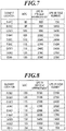
- FIG. 7 shows a change of the life of the superconducting elements 81 to 89 in the example (Example 2) of FIG. 6 in which the superconducting elements 81 to 89 are disposed sequentially at the element positions A to I in the written order.
- FIG. 8 shows a change of the life of the superconducting elements 89 to 81 in Comparison 2 in which the superconducting elements 89 to 81 are disposed sequentially at the element positions A to I in the written order.
- the superconducting elements 81 to 89 are disposed such that the upper superconducting element of each pair of two vertically adjacent superconducting elements has a higher critical current than the lower superconducting element.
- the superconducting elements in the middle and upper lines have an extended life than when they are disposed solely since they are exposed to nitrogen gas bubbles from other superconducting elements located below.
- Example 2 the life can be extended in all of the superconducting elements 81 to 86 that are likely to have a short life. Therefore, it is possible to achieve effective life extension of the superconducting fault current limiter.
- the superconducting fault current limiter according to the second embodiment is an example in which nine superconducting elements are arranged in a plane.
- the number of superconducting elements can be changed to any number as long as they can be disposed such that the upper superconducting element of each pair of two vertically adjacent superconducting elements has a lower critical current than the lower superconducting element.
- the superconducting fault current limiter according to the second embodiment is an example in which the element groups each composed of the parallely-connected plurality of superconducting elements are connected in series.
- the connection is not limited thereto.
- elements groups each composed of a serially-connected plurality of superconducting elements may be gathered by parallel connection.
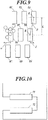
- the aligning direction of the vertically adjacent superconducting elements may be tilted to some extent from the vertical direction as illustrated in FIG. 9 .
- the intersection of the horizontal center line and the vertical center line of the flat plate of a superconducting element is defined as the center g
- the tilt angle ⁇ of the line connecting the centers g, g of two vertically adjacent superconducting elements e.g. the superconducting elements 83, 86
- the upper superconducting element 83 can be exposed to nitrogen gas bubbles produced on the lower superconducting element 86.
- the superconducting elements can be disposed so that each pair of two vertically adjacent superconducting elements satisfies the following expression (1) or (2): 0 ° ⁇ tan ⁇ 1 ⁇ / L ⁇ 70 ° 0 ⁇ ⁇ ⁇ L ⁇ tan 70 ° where ⁇ is the horizontal distance that bubbles from a superconducting element reach when the current exceeds the critical current, provided ⁇ ⁇ ⁇ .
- the superconducting elements 81 to 89 can be disposed such that the arrangement is tilted in the vertical direction within the above-described range.
- FIG. 9 illustrates an arrangement that is tilted only to the right, the arrangement may also be tilted to the left within the same numerical range.
- a plurality of sets each composed of a plurality of superconducting elements arranged in a plane may be used, in which the plurality of sets are disposed parallel to each other so that the superconducting elements are arranged three-dimensionally as a whole.
- a three-dimensional arrangement can be achieved by using two or more sets each composed of the nine superconducting elements 81 to 89 of FIG. 6 and disposing the sets such that they are parallel to each other at the same height and are aligned in a direction intersecting with their planes, e.g. in the horizontal direction.
- This arrangement allows bringing flows of vaporized gas from a plurality of lower superconducting elements together to the upper superconducting elements. Therefore, it is possible to achieve life extension of a superconducting element with a low critical current and thus of the superconducting fault current limiter.
- the superconducting elements 71, 72 are disposed such that their longitudinal direction is in the vertical direction in the above-described example, they may be disposed such that their longitudinal direction is in the horizontal direction as illustrated in FIG. 10 .
- the superconducting elements 81 to 89 are disposed such that their longitudinal direction is in the vertical direction in the above-described example, they may be disposed such that their longitudinal direction is in the horizontal direction as illustrated in FIG. 10 .
- the superconducting elements 81 to 89 are disposed such that their longitudinal direction is in the vertical direction in the above-described example, they may be disposed such that their longitudinal direction is in the horizontal direction as illustrated in FIG. 10 .
- the superconducting elements 81 to 89 are disposed such that their longitudinal direction is in the horizontal direction as illustrated in FIG. 10 .
- the superconducting elements 71, 72 When the superconducting elements 71, 72 are disposed such that their longitudinal direction is in the horizontal direction, they can be disposed such that their flat plate surfaces are parallel to the horizontal plane.
- FIG. 6 illustrates an example in which the superconducting elements 81 to 89 are disposed such that their longitudinal direction is in the vertical direction, they may be disposed such that their longitudinal direction is in the horizontal direction as illustrate in FIG. 11 .
- the superconducting elements 81 to 89 When the superconducting elements 81 to 89 are disposed such that their longitudinal direction is in the horizontal direction, they can be disposed such that their flat plate surfaces are parallel to the horizontal plane.
- the superconducting elements 81, 82, 83 are connected in parallel, and the superconducting elements 84, 85, 86 and the superconducting elements 87, 88, 89 are connected similarly, and these three groups of superconducting elements are connected in series.
- the superconducting elements 81 to 89 may be connected in any manner. For example, they may be connected in series as illustrated in FIG. 12 .
- FIG. 12 illustrates an example of an inductive arrangement in which the superconducting elements 81 to 89 are disposed such that an electric current flows in the same direction through them, they may be disposed in a non-inductive arrangement.
- the superconducting elements 81 to 89 are constituted by thin film elements using a thin film superconducting material, and the superconducting elements 81 to 89 are connected in series.
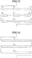
- the superconducting elements 81 to 89 may be disposed in an arrangement in which three superconducting elements 81, 82, 83 are aligned horizontally, it then turns back therebelow and the three superconducting elements 84, 85, 86 are aligned horizontally in the opposite direction, and it then turns back again therebelow and the three superconducting elements 87, 88, 89 are aligned horizontally in the opposite direction.
- the flow direction of an electric current alternates between the three groups of the superconducting elements, which provides a non-inductive arrangement.
- the non-inductive arrangement is not limited to the example of FIG. 13 .
- the superconducting elements 81, 82, 83 are constituted by an element of a superconducting wire (an element longer than the superconducting elements of FIG. 13 ), and the superconducting elements 81 to 83 are connected in series. Then, the superconducting elements 81 is disposed horizontally, the arrangement then turns back therebelow and the superconducting element 82 is disposed horizontally in the opposite direction, and the arrangement then turns back again therebelow and the superconducting element 83 is disposed horizontally in the opposite direction. In this case, the flow direction of an electric current alternates between the three superconducting elements, which provides a non-inductive arrangement.
- the element group By disposing the superconducting elements or the superconducting wires in a meander non-inductive arrangement as in the examples of FIG. 13 and FIG. 14 , the element group exhibits a reduced inductance compared to the configuration of FIG. 12 . Therefore, a voltage at a rated current in the superconducting fault current limiter 10 can be reduced.
- the superconducting elements When the superconducting elements have an easily deformable wire shape instead of a strip shape, they may be formed in any shape.
- two or more superconducting element units 100 each of which includes superconducting elements 101 to 106 formed in a swirly coil shape on the upper surface of a support plate 110 as illustrated in FIG. 15 , may be employed, and the units may be stacked in a vertical direction.
- a mesh or a number of slits or small holes is/are formed in an area 111 where the superconducting elements 101 to 106 are disposed in a coil shape so that bubbles can pass through it/them between the front side and the back sides.
- At least one or more superconducting element unit 100 is disposed below a superconducting element unit 100 that includes a superconducting element with the lowest critical current in all of the superconducting elements disposed in the vertically arranged plurality of superconducting element units 100. It is more desirable that the superconducting element unit 100 that includes the superconducting element with the lowest critical current is disposed on the top.
- the number of superconducting element units may be changed to any number of two or more, and the number of superconducting element in each superconducting element unit 100 may be changed to any number of one or more.
- the superconducting element of the superconducting element unit 100 may be formed in a non-inductive coil shape as illustrated in FIG. 16 . That is, a wire superconducting element 101 folded in two at the center is wound in a coil shape. When an electric current flows from one end to the other end, the electric current flows in the opposite direction between adjacent parts of the wire superconducting element across the folded center. With this configuration, the inductance of the element group is reduced. Therefore, a voltage generated at a rated current in the superconducting fault current limiter 10 can be reduced.
- a plurality of wire superconducting elements may be wound in the coil shape as illustrated in FIG. 15 .
- the above-described critical current values of the superconducting elements 71, 72, 81 to 89 are merely examples and may be changed to any value as long as the above-described conditions of the element arrangement and the critical current are met.
- some of the plurality of superconducting elements are arranged in a horizontal plane.
- the number and the arrangement of the superconducting elements on a plane are not limited to the above-described configuration.
- the superconducting element with the lowest critical current is disposed in an area where bubbles from the other superconducting elements reach as illustrated in FIG. 9 . It is desirable that the plurality of superconducting elements are disposed such that one with a lower critical current is disposed at a higher location.
- the life of the superconducting element with the lowest critical current can be extended, and it is thus possible to achieve life extension of the overall device.
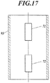
- FIG. 17 illustrates an example in which the superconducting elements 71, 72 are surrounded, and the superconducting elements 81 to 89 may also be fully surrounded by the element cover 93.
- the element cover 93 can restrain diffusion of nitrogen gas bubbles that is produced on the lower superconducting element in the event of a fault current so as to lead the bubbles upward to expose the upper superconducting element to the bubbles and the resultant liquid flow more efficiently. Therefore, it is possible to perform more efficient cooling.
- An element cover having a different shape other than cylindrical and frame shapes that has open upper and lower ends and is capable of restraining diffusion of nitrogen gas bubbles may be used to surround the superconducting elements 71, 72.
- the superconducting elements have a strip shape. However, they may have any shape such as a bar shape, a wire shape, a sheet shape and the like. Further, the superconductor of the superconducting elements is not limited to that of the above-described example, and the superconducting elements may be made of other superconducting materials. In this case, it is desirable to suitably select a refrigerator and a liquid coolant that are capable of cooling the selected superconducting material to a temperature at which the selected superconducting material can maintain the superconducting state.
- FIG. 18 is a cross sectional view of the superconducting fault current limiter 10A, taken along a vertical plane.
- the superconducting fault current limiter 10A includes a coolant vessel 20, a lid member 30, a refrigerator 40, and an element cover 93 that surrounds two superconducting elements 71, 72 in liquid nitrogen 60 in the coolant vessel 20.
- the superconducting fault current limiter 10A When the current flowing though the superconducting fault current limiter 10A is within the range not exceeding the critical current of both of the two superconducting elements 71, 72, it remains in the superconducting state. In the event a fault current that exceeds the critical current of at least either one of them, it changes to the normal conducting state to have an electric resistance so that the excessive current is prevented from flowing to a device under protection.
- the life of a superconducting element is likely to be decreased as the accumulated time exposed to a certain high temperature condition is increased. Therefore, the faster the cooling from a high temperature condition caused by a fault current is, the more the element life can be extended. Accordingly, by vertically arranging the superconducting elements 71, 72 as described above, the life of at least the superconducting element 71 is extended, and the life of the overall superconducting fault current limiter 10A is thereby extended.
- FIG. 20 is a cross sectional view of the element cover 93 taken along the center line
- FIG. 21 is a plan view thereof.
- the element cover 93 which has a circular shape in a plan view, is a cylinder that is disposed in the coolant vessel 20 such that the center line C is in the vertical direction.
- the element cover 93 has open upper and lower ends.
- the two superconducting elements 71, 72 are vertically arranged.
- the superconducting elements 71, 72 are disposed such that one superconducting element 71 is located over the other superconducting element 72.
- this arrangement allows nitrogen gas bubbles and a resultant liquid flow that are produced by film boiling on the lower superconducting element 72 to be utilized to improve the cooling efficiency of the upper superconducting element 71.
- diffusion of the bubbles decreases the performance of removing the film boiling nitrogen gas on the upper superconducting element 71. This makes it difficult to sufficiently improve the cooling efficiency.
- the superconducting elements 71, 72 are surrounded by the element cover 93 so that the bubbles from the lower superconducting element 72 are prevented from diffusion. This allows effectively leading the bubbles and liquid flow to the upper superconducting element 71.
- the centers g of the superconducting elements 71, 72 refer to the midpoints of the superconducting elements 71, 72 in the longitudinal direction in a plan view as well as in the transverse direction in a plan view and in the vertical direction.
- the centers g are coincide with the centers of gravity of the superconducting elements 71, 72 when they have a rectangular plate (cuboid) shape and a uniform density.
- the superconducting elements 71, 72 are disposed such that the centers g, g are both on the center line C of the element cover 93.
- the superconducting elements 71, 72 are disposed such that the following expression (3) is satisfied, where L is the inter-center distance between the centers g, g of the two superconducting elements 71, 72 in the vertical direction, R is the distance from the centers g of the superconducting elements 71, 72 to the inner surface of the element cover 93 in the longitudinal direction of the superconducting elements 71, 72, W is the length of the superconducting elements 71, 72 in the longitudinal direction in a plan view, r1 is the intersection of the line extending from the center g of one superconducting element 71 in the longitudinal direction of the superconducting element 71 with the inner surface of the element cover 93, r2 is the intersection of the line extending from the center g of the other superconducting element 72 in the longitudinal direction of the superconducting element 72 with the inner surface of the element cover 93, and ⁇ is the intersecting angle between the line connecting the center g of the other superconducting element 72 and the intersection r1
- R is set to R > W/2 so that the gaps are not completely closed.
- the distance ⁇ from the center g which the bubbles reach when the current flowing through the superconducting elements 71, 72 exceeds the critical current is generally within a certain range (see FIG. 19 ). Therefore, the distance R is desirably equal to or less than ⁇ (R ⁇ ⁇ ).
- the lower superconducting element 72 is disposed such that the lower end thereof is located higher than the lower end of the element cover 93. With this configuration, bubbles produced by film boiling are not leaked out of the element cover 93 and can be effectively led upward.
- the solid line represents the time required to cool the sole superconducting element 71 to a coolant temperature (77 [K]) when the superconducting element 71 at room temperature (303 [K]) is put into the liquid nitrogen in the coolant vessel 20, and the temperature change during the process.
- the dashed line represents the time required to cool the sole superconducting element 71 to a coolant temperature (77 [K]) when the superconducting element 71 at room temperature (303 [K]) and a metal frame at room temperature that serves as a source of film boiling bubbles are disposed in the coolant vessel 20, and the temperature change during the process.
- the frame was disposed obliquely below the superconducting element 71 on the line tilted by 70° with respect to the vertical line extending from the center g.
- the nitrogen gas bubbles and the liquid flow therefrom improve the cooling efficiency of a superconducting element in film boiling.
- the lower superconducting element 72 serves as a bubble source when a fault current exceeding the critical current flows. Therefore, even when film boiling occurs on the upper superconducting element 71, it is possible to perform faster cooling.
- FIG. 23 shows the result of comparison in recovery time to the coolant temperature after an electric current was applied to the superconducting elements 71, 72 to heat them between conditions with and without the element cover 93 provided in the coolant vessel 20.
- the comparison is made in the amount of heat generated and the recovery time when an electric current is applied to the superconducting elements 71, 72 to heat them.
- the superconducting elements 71, 72 were disposed in the coolant vessel 20 as illustrated in FIG. 20 in which the intersecting angle was set to 30°.
- the symbol “ ⁇ ” represents the condition with the element cover
- the symbol “ ⁇ ” represents the condition without the element cover.
- the recovery time is decreased in the condition with the element cover 93.
- the greater the amount of heat generated the larger the difference in recovery time.
- the recovery time was 3.7 [sec] in the condition without the element cover 93.
- the recovery time was 3.1 [sec] in the condition with the element cover 93, which was reduced by approximately 20%.
- FIG. 24 shows a list of the recovery time of the superconducting element 71 from a heated state in a condition without the element cover and in conditions of an intersecting angle ⁇ regarding the vertical arrangement of the superconducting elements 71, 72 with respect to the element cover 93 of 20°, 25°, 30°, 45°, 60°, 70°, 75° and 80°.
- the distance R from the centers of the superconducting elements to the element cover is set to a constant value while only the inter-center distance L between the two superconducting elements 71, 72 is changed to change the intersecting angle ⁇ .
- the other arrangement configurations are the same as the example of FIG. 20 .
- the amount of heat generated in each of the superconducting elements 71, 72 were set to 400 [J].
- FIG. 25 is a graph illustrating the relationship between the inter-element distance and the mutual inductance, which is calculated based on a simulation, where the solid line is the result when the flat plate surfaces of the superconducting elements 71, 72 are parallel to the vertical direction (the arrangement of FIG. 20 ), and the dashed line is the result when the flat plate surfaces of the superconducting elements 71, 72 are both parallel to the horizontal plane.
- the inter-element distance refers to the distance from the upper end surface of the lower superconducting element 72 to the lower end surface of the upper superconducting element 71.
- the superconducting elements 71, 72 had a size of 210x30x1 (width in the horizontal direction x width in the vertical direction x width in the thickness direction of paper in the arrangement of FIG. 20 , all in [mm]). As illustrated in the figure, when the inter-element distance between the superconducting element 71, 72 is less than approximately 20 [mm], the mutual inductance is drastically increased. Accordingly, it is desirable that inter-element distance between the superconducting elements 71, 72 is equal to or more than 20 [mm].
- the inter-center distance L between the two superconducting elements 71, 72 is equal to the sum of the above-described inter-element distance which is determined considering the mutual inductance (20 [mm]) + the width of the elements in the vertical direction (30 [mm]). Accordingly, it is desirably L ⁇ 50 [mm].
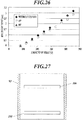
- FIG. 26 shows the result of comparison in recovery time when the amount of heat generated by applying an electric current to the superconducting element 71 is changed within the range of 0 to 480 [J] between a condition of an intersecting angle of 45°, which is within the suitable range determined by the comparison of FIG. 24 , a condition of an intersecting angle of 80°, which is out of the suitable range, and a condition without the element cover 93.
- the symbol “ ⁇ ” represents the condition without the element cover
- the symbol “ ⁇ ” represents the condition of an intersecting angle of 45° (with the element cover)
- the symbol “ ⁇ ” (patterned in FIG. 26 ) represents the condition of an intersecting angle of 80° (with the element cover).
- the superconducting fault current limiter 10A is configured such that one superconducting element 71 is disposed over the other superconducting element 72 in the liquid nitrogen 60 in the coolant vessel 20.
- this arrangement allows utilizing nitrogen gas bubbles and a resultant liquid flow that are produced by the lower superconducting element 72 in order to improve the cooling efficiency of the upper superconducting element 71 in film boiling.
- This improvement of the cooling efficiency by the vertical arrangement of the superconducting elements 71, 72 is also confirmed by the result of FIG. 22 in which the cooling efficiency was improved when a film boiling nitrogen gas source is provided.
- the superconducting fault current limiter 10A includes the element cover 93 that surrounds the two superconducting elements 71, 72. With this configuration, bubbles produced on the lower superconducting element 72 are efficiently led to the upper superconducting element 71. Therefore, the improvement of the cooling efficiency is achieved. This improvement of the cooling efficiency by the element cover 93 is also confirmed by the result of the comparative test of FIG. 23 in which the recovery time to the cooling temperature is compared between conditions with and without the element cover 93.
- the two superconducting elements 71, 72 are arranged in the element cover such that the distance R from the centers g, g to the inner surface of the element cover 93 and the inter-center distance L between the two superconducting elements 71, 72 satisfy tan -1 (L/R) ⁇ 70°.
- improvement of the cooling efficiency of the upper superconducting element 71 can be achieved.
- This improvement of the cooling efficiency by the arrangement of the superconducting elements is also confirmed by the result of the comparative test of FIG. 24 and FIG. 26 in which the intersecting angle ⁇ , which is determined by L and R, is changed.
- the inter-element distance of the superconducting elements 71, 72 is set to 20 [mm] or more. With this configuration, the influence of the mutual inductance of the superconducting elements 71, 72 can be reduced. To satisfy this condition and the like, it is desirable that the intersecting angle ⁇ , which is determined based on the arrangement of the superconducting elements 71, 72, is within the range of 25° or more.
- the lower superconducting element 72 in the element cover 93 is disposed such that the lower end thereof is located higher than the lower end of element cover 93.
- the element cover 93 is provided in the coolant vessel 20, and the superconducting elements 71, 72 are arranged relative to the element cover 93 such that the above-described arrangement conditions are satisfied.
- the upper superconducting element 71 can be effectively cooled so that the life thereof can be extended. Therefore, it becomes possible to achieve life extension of the superconducting fault current limiter 10A.
- a plurality of the above-described superconducting element units 100 may be provided, which may be vertically arranged in the element cover 93. In this case, it is desirable that the superconducting element units 100 are all parallel to a horizontal plane.
- the superconducting element unit 100 is disposed below a superconducting element unit 100 that includes a superconducting element with the lowest critical current. It is more desirable that the superconducting element unit 100 including the superconducting element with the lowest critical current is disposed on the top.
- the improvement of the cooling efficiency by the element cover 93 can be achieved as long as the plurality of superconducting elements are vertically arranged.
- the shape of the above-described element cover 93 is not limited to a cylindrical shape, and it may be a tube or frame with any shape in a plan view that has open upper and lower ends.
- an element cover 93A which is a frame with a rectangular shape in a plan view, may also be used.
- the element cover may also be formed in a polygonal, ellipse or oval shape. It is desirable that the element cover has a uniform cross section over the whole length in the vertical direction so that a through hole is formed over the whole length.
- the element cover 93A is a rectangular frame
- the superconducting elements 71, 72 are disposed such that the expression tan -1 (L/R) ⁇ 70° is satisfied in the longitudinal direction. Considering the influence of the mutual inductance, it is more preferred that the expression 25° ⁇ tan -1 (L/R) ⁇ 70° is satisfied.
- the superconducting elements 71, 72 may be surrounded by a cover with a different shape other than a tube or frame shape as long as it has open upper and lower ends and is capable of restraining diffusion of nitrogen gas bubbles.
- the superconducting elements have a strip shape.
- the shape is not limited thereto, and they may have any shape such as bar, wire and sheet shapes.
- Some shapes of the superconducting elements may have no specific longitudinal direction in a plan view (e.g. a circular shape in a plan view). In such cases, any certain direction may be set as the longitudinal direction to define the distance R from the centers of the superconducting elements to the inner surface of the element cover in the set longitudinal direction, and the superconducting elements may be disposed such that the expression (3) is satisfied.
- the superconducting elements 71, 72 are disposed such that their longitudinal direction is in the horizontal direction. However, they may be disposed such that their longitudinal direction is in the vertical direction.
- the superconducting elements 71, 72 are disposed such that their flat plate surfaces are parallel to the vertical direction. However, they may be disposed such that their flat plane surfaces are parallel to the horizontal direction.
- the number of superconducting elements is not limited to two, and a larger number of superconducting elements may be used.
- the superconducting elements may be all connected in series, or they may be connected by a combination of serial and parallel connections.
- they may be arranged in multiple tiers instead of the upper and lower two tiers. In this case, it is desirable that at least one pair of vertically adjacent two superconducting elements are disposed such that the expression (3) is satisfied. It is more desirable that all pairs of vertically adjacent two superconducting elements are disposed such that the expression (3) is satisfied.
- the element covers 93, 93 may be provided for the respective sets 73, 74 of the superconducting elements so that the sets are individually disposed therein.
- the superconducting fault current limiter includes a plurality of sets 73, 74 each composed of vertically arranged superconducting elements, they may be disposed in a single element cover.
- the superconducting element with a lower critical current is likely to have a shorter life. Therefore, it is desirable to dispose the superconducting element with a lower critical current at a higher location. By improving the cooling efficiency of the superconducting element with a shorter life and thereby extending its life, it becomes possible to achieve life extension of the superconducting fault current limiter more effectively.
- both longitudinal ends of the superconducting elements are located at the same distance from the inner surface of the element cover (the centers g are located on the center line C), it is desirable that the above-described expression (3) is satisfied in both ends in the longitudinal direction.
- the present invention which is a device or a method used in a power system and the like, is applicable to preventing a short-circuit and the like.
Landscapes
- Engineering & Computer Science (AREA)
- Microelectronics & Electronic Packaging (AREA)
- Power Engineering (AREA)
- Physics & Mathematics (AREA)
- Thermal Sciences (AREA)
- Emergency Protection Circuit Devices (AREA)
- Containers, Films, And Cooling For Superconductive Devices (AREA)
Claims (12)
- Supraleitender Fehlstrombegrenzer (10, 10A) mit supraleitenden Elementen (71, 72, 81 - 89), die in einem supraleitenden Zustand sind, wenn ein elektrischer Strom innerhalb eines bestimmten Bereichs von elektrischen Stromwerten fließt und die in einen normalleitenden Zustand übergehen, wenn ein den Bereich überschreitender Fehlstrom fließt, mit:einem Kühlgefäß (20), das ein flüssiges Kühlmittel (60) die mehreren supraleitenden Elemente (71, 72, 81 - 89) aufnimmt; undeine Kühleinrichtung (40), die das flüssige Kühlmittel (60) in dem Kühlgefäß (20) kühlt,wobei eines der mehreren supraleitenden Elemente (71, 72, 81 - 89) ein supraleitendes Element mit einem kleinsten kritischen Strom ist, das über einem weiteren supraleitenden Element in dem flüssigen Kühlmittel (60) angeordnet ist,gekennzeichnet durcheine Element-Abdeckung (93, 93A), die ein offenes oberes und unteres Ende aufweist und die in dem Kühlgefäß (20) die mehreren supraleitenden Elemente (71, 72, 81 - 89) einfassend angeordnet ist.
- Supraleitender Fehlstrombegrenzer gemäß Anspruch 1, wobei die mehreren supraleitenden Elemente (71, 72, 81 - 89) in dem flüssigen Kühlmittel (60) derart angeordnet sind, dass ein supraleitendes Element mit einem kleineren kritischen Strom an einer höheren Position angeordnet ist.
- Supraleitender Fehlstrombegrenzer gemäß Anspruch 1, wobei die mehreren supraleitenden Elemente (71, 72, 81 - 89) in einer Ebene parallel zu einer vertikalen Richtung angeordnet sind, und
wobei jedes Paar von vertikal nebeneinanderliegenden zwei supraleitenden Elementen derart angeordnet ist, dass ein oberes supraleitendes Element einen kleineren kritischen Strom aufweist als ein unteres supraleitendes Element. - Supraleitender Fehlstrombegrenzer gemäß Anspruch 3, wobei mehrere Gruppen, von denen jede aus den mehreren supraleitenden Elementen (81 - 89), die in der Ebene parallel zu der vertikalen Richtung angeordnet sind, zusammengesetzt ist, derart angeordnet sind, dass die mehreren supraleitenden Elemente insgesamt dreidimensional angeordnet sind.
- Verfahren zum Kühlen supraleitender Elemente (71, 72, 81 - 89) eines supraleitenden Fehlstrombegrenzers (10, 10A), der die supraleitenden Elemente (71, 72, 81 - 89) aufweist, die in einem supraleitenden Zustand sind wenn ein elektrischer Strom innerhalb eines bestimmten Bereichs von elektrischen Stromwerten fließt und die in einen normalleitenden Zustand übergehen, wenn den Bereich überschreitender ein Fehlstrom fließt, umfassend:Anordnen der mehreren supraleitenden Elemente (71, 72, 81 - 89) derart, dass ein supraleitendes Element mit dem kleinsten kritischen Strom über einem weiteren supraleitenden Element in einem flüssigen Kühlmittel (60) in einem Kühlgefäß (20) angeordnet ist; undKühlen des supraleitenden Elements mit dem kleinsten kritischen Strom durch Nutzung von Bläschen, die an dem weiteren supraleitenden Element entstehen, das unter dem supraleitenden Element mit dem kleinsten kritischen Strom angeordnet ist, wobei die mehreren supraleitenden Elemente (71, 72, 81 - 89) innerhalb einer Element-Abdeckung (93, 93A) angeordnet sind, die offene obere und untere Enden aufweist und die in dem Kühlgefäß (20) angeordnet ist.
- Verfahren zum Kühlen supraleitender Elemente (71, 72, 81 - 89) eines supraleitenden Fehlstrombegrenzers (10, 10A) gemäß Anspruch 5, wobei das supraleitende Element mit dem kleinsten kritischen Strom gekühlt wird, wenn das flüssige Kühlmittel auf einer Oberfläche des supraleitenden Elements mit dem kleinsten kritischen Strom in einem Filmverdampfungs-Zustand ist.
- Verfahren zum Kühlen supraleitender Elemente (71, 72, 81 - 89) eines supraleitenden Fehlstrombegrenzers (10, 10A) gemäß Anspruch 5 oder 6, wobei die mehreren supraleitenden Elemente (71, 72, 81 - 89) in dem flüssigen Kühlmittel (60) derart angeordnet werden, dass ein supraleitendes Element mit einem kleineren kritischen Strom an einer höheren Position angeordnet ist.
- Verfahren zum Kühlen supraleitender Elemente (71, 72, 81 - 89) eines supraleitenden Fehlstrombegrenzers (10, 10A) gemäß Anspruch 5 oder 6, wobei die mehreren supraleitenden Elemente (71, 72, 81 - 89) in einer Ebene parallel zu einer vertikalen Richtung angeordnet werden, und
wobei die mehreren supraleitenden Elemente (71, 72, 81 - 89) derart angeordnet werden, dass ein höher angeordnetes supraleitendes Element jedes Paars von vertikal nebeneinanderliegenden zwei supraleitenden Elementen einen kleineren kritischen Strom aufweist als ein darunter liegendes supraleitendes Element. - Verfahren zum Kühlen supraleitender Elemente (71, 72, 81 - 89) eines supraleitenden Fehlstrombegrenzers (10, 10A) gemäß Anspruch 8, wobei mehrere Gruppen, von denen jede aus den mehreren supraleitenden Elementen (81 -. 89), die in der Ebene parallel zu der vertikalen Richtung angeordnet werden, zusammengesetzt ist, derart angeordnet sind, dass die mehreren supraleitenden Elemente insgesamt dreidimensional angeordnet sind.
- Verfahren zum Kühlen supraleitender Elemente (71, 72, 81 - 89) eines supraleitenden Fehlstrombegrenzers (10, 10A), der die supraleitenden Elemente (71, 72, 81 - 89) aufweist, die in einem supraleitenden Zustand sind wenn ein elektrischer Strom innerhalb eines bestimmten Bereichs von elektrischen Stromwerten fließt und die in einen normalleitenden Zustand übergehen, wenn ein den Bereich überschreitender Fehlstrom fließt, umfassend:vertikales Anordnen von zumindest zwei der mehreren supraleitenden Elemente (71, 72, 81 - 89) innerhalb einer Element-Abdeckung (93, 93A), die offene obere und untere Enden aufweist und die in dem flüssigen Kühlmittel (60) in dem Kühlgefäß (20) angeordnet ist; undZuleiten von Bläschen, die auf einem unteren supraleitenden Element der mehreren supraleitenden Elemente (71, 72, 81 - 89) entstehen, zu einem oberen supraleitenden Element der mehreren supraleitenden Elemente (71, 72, 81 - 89);wobei das obere supraleitende Element mit dem kleinsten kritischen Strom der mehreren supraleitenden Elemente (71, 72, 81 - 89) gekühlt wird, wenn das flüssige Kühlmittel auf einer Oberfläche des oberen supraleitenden Elements in einem Filmverdampfungs-Zustand ist.
- Verfahren zum Kühlen der supraleitenden Elemente (71, 72, 81 - 89) des supraleitenden Fehlstrombegrenzers (10, 10A) gemäß Anspruch 10, wobei das untere supraleitende Element der zumindest zwei vertikal in der Element-Abdeckung (93, 93A) angeordneten supraleitenden Elemente derart angeordnet wird, dass ein unteres Ende des unteren supraleitenden Elements höher liegt als ein unteres Ende der Element-Abdeckung.
- Verfahren zum Kühlen der supraleitenden Elemente (71, 72, 81 - 89) des supraleitenden Fehlstrombegrenzers (10, 10A) gemäß Anspruch 10 oder 11, wobei die vertikal angeordneten zwei supraleitenden Elemente so angeordnet werden, dass der nachfolgende Ausdruck (I) erfüllt ist,

Applications Claiming Priority (3)
| Application Number | Priority Date | Filing Date | Title |
|---|---|---|---|
| JP2013025069 | 2013-02-13 | ||
| JP2013025068 | 2013-02-13 | ||
| PCT/JP2014/052855 WO2014126006A1 (ja) | 2013-02-13 | 2014-02-07 | 超電導限流器及び超電導限流器内の超電導素子の冷却方法 |
Publications (3)
| Publication Number | Publication Date |
|---|---|
| EP2945199A1 EP2945199A1 (de) | 2015-11-18 |
| EP2945199A4 EP2945199A4 (de) | 2016-10-12 |
| EP2945199B1 true EP2945199B1 (de) | 2018-06-27 |
Family
ID=51354010
Family Applications (1)
| Application Number | Title | Priority Date | Filing Date |
|---|---|---|---|
| EP14751627.2A Not-in-force EP2945199B1 (de) | 2013-02-13 | 2014-02-07 | Supraleitender fehlerstrombegrenzer und kühlverfahren für ein supraleitendes element in dem supraleitenden fehlerstrombegrenzer |
Country Status (3)
| Country | Link |
|---|---|
| US (1) | US10178799B2 (de) |
| EP (1) | EP2945199B1 (de) |
| WO (1) | WO2014126006A1 (de) |
Families Citing this family (5)
| Publication number | Priority date | Publication date | Assignee | Title |
|---|---|---|---|---|
| CN104410065B (zh) * | 2014-10-31 | 2015-10-21 | 广东电网有限责任公司电力调度控制中心 | 一种受端电网限制短路电流的多目标决策方法 |
| EP3121860B1 (de) * | 2015-07-21 | 2020-11-25 | Nexans | Anordnung zur strombegrenzung in einem der stromversorgung dienenden netzwerk |
| RU191803U1 (ru) * | 2019-05-13 | 2019-08-22 | Федеральное государственное казенное военное образовательное учреждение высшего образования "Военный учебно-научный центр Военно-Морского Флота "Военно-морская академия им. Адмирала Флота Советского Союза Н.Г. Кузнецова" | Сверхпроводящее защитное устройство радиоприемных устройств с автокомпенсатором |
| US10765033B1 (en) * | 2019-05-23 | 2020-09-01 | Microsoft Technology Licensing, Llc | Immersion cooling enclosures with insulating liners |
| CN110660549A (zh) * | 2019-10-09 | 2020-01-07 | 全球能源互联网研究院有限公司 | 避雷器及输电系统 |
Family Cites Families (14)
| Publication number | Priority date | Publication date | Assignee | Title |
|---|---|---|---|---|
| JPS6285449A (ja) | 1985-10-09 | 1987-04-18 | Fujitsu Ltd | 半導体装置の冷却構造 |
| JPS63299181A (ja) | 1987-05-29 | 1988-12-06 | Hitachi Ltd | 超電導装置 |
| JPH02269413A (ja) * | 1989-04-10 | 1990-11-02 | Toyota Motor Corp | 限流器 |
| JPH0423457A (ja) | 1990-05-18 | 1992-01-27 | Fujitsu Ltd | 浸漬冷却装置 |
| JPH06104358A (ja) | 1992-09-04 | 1994-04-15 | Hitachi Ltd | 液体により冷却される電子装置 |
| JP3442923B2 (ja) * | 1996-03-14 | 2003-09-02 | 東京電力株式会社 | 超電導装置 |
| JP3866422B2 (ja) * | 1998-08-19 | 2007-01-10 | 東京電力株式会社 | 超電導限流器 |
| KR100505054B1 (ko) * | 2003-09-30 | 2005-08-02 | 엘에스산전 주식회사 | 초전도 저항형 한류기 |
| JP4081021B2 (ja) * | 2004-01-09 | 2008-04-23 | 株式会社東芝 | 超電導限流素子 |
| JP2008518581A (ja) * | 2004-10-26 | 2008-05-29 | ノヴ テクノロジーズ インコーポレイテッド | 漏電制限システム |
| EP1830419B1 (de) * | 2006-03-02 | 2009-07-01 | Theva Dünnschichttechnik GmbH | Resistiver Strombegrenzer |
| JP5060064B2 (ja) * | 2006-05-25 | 2012-10-31 | 株式会社東芝 | 超電導限流器 |
| JP2012146821A (ja) * | 2011-01-12 | 2012-08-02 | Tokyo Denki Univ | 超電導コイル装置 |
| JP2013038333A (ja) * | 2011-08-10 | 2013-02-21 | Nissin Electric Co Ltd | 超電導限流器 |
-
2014
- 2014-02-07 EP EP14751627.2A patent/EP2945199B1/de not_active Not-in-force
- 2014-02-07 WO PCT/JP2014/052855 patent/WO2014126006A1/ja not_active Ceased
- 2014-02-07 US US14/767,878 patent/US10178799B2/en not_active Expired - Fee Related
Non-Patent Citations (1)
| Title |
|---|
| None * |
Also Published As
| Publication number | Publication date |
|---|---|
| EP2945199A1 (de) | 2015-11-18 |
| WO2014126006A1 (ja) | 2014-08-21 |
| US10178799B2 (en) | 2019-01-08 |
| US20150382505A1 (en) | 2015-12-31 |
| EP2945199A4 (de) | 2016-10-12 |
Similar Documents
| Publication | Publication Date | Title |
|---|---|---|
| US10178799B2 (en) | Superconducting fault current limiter and cooling method for superconducting element within superconducting fault current limiter | |
| KR102852874B1 (ko) | 나선형 홈, 스택된 플레이트, 비절연 초전도 자석을 위한 전도체 및 냉각제 스킴 | |
| US9508477B2 (en) | Superconducting magnet system | |
| CN101542649B (zh) | 超导线圈及用于该超导线圈的超导体 | |
| JP2005109511A (ja) | 超伝導抵抗型限流器 | |
| US20180315530A1 (en) | Method and apparatus for cooling a superconducting device immersed in liquid nitrogen | |
| JP7348410B1 (ja) | サイクロトロン用の超電導マグネットシステム及びそれを有するサイクロトロン | |
| EP2860781B1 (de) | Kühlbehälter | |
| US20160180996A1 (en) | Superconducting magnet system | |
| CA2150138C (en) | Gas-cooled bushing in cryotanks for superconducting applications | |
| JP6117126B2 (ja) | 超電導限流器及び超電導限流器内の超電導素子の冷却方法 | |
| CN111223631B (zh) | 超导磁体冷却设备及磁共振成像设备 | |
| US20050081538A1 (en) | Cryogenic compressor enclosure device and method | |
| Kiyoshi et al. | Generation of magnetic fields over 21 T in a 61 mm clear bore using low copper ratio (Nb, Ti)/sub 3/Sn conductors | |
| WO2013052354A1 (en) | Techniques for sub-cooling in a superconducting system | |
| JP5950951B2 (ja) | 超電導限流器及び超電導限流器内の超電導素子の冷却方法 | |
| KR102840080B1 (ko) | 액화수소와 연료전지를 이용한 초전도코일 시스템 | |
| US8264802B2 (en) | Current limiting device | |
| JP2515813B2 (ja) | 超電導機器用電流リ−ド | |
| Chang et al. | Performance of heat exchanger for subcooling liquid nitrogen with a GM cryocooler | |
| Kiyoshi et al. | Operation of a 20-T superconducting magnet with a large bore | |
| KR102819544B1 (ko) | 냉각 효율을 높인 열 전도체 구조를 갖는 냉각 유닛이 구비된 초전도 한류기 | |
| Inoue et al. | High-field facilities under development and construction at the National Research Institute for Metals, Japan | |
| JP2013143474A (ja) | 超電導マグネット装置及びその電流リード | |
| Satow et al. | Completion and trial operation of the superconducting magnets for the Large Helical Device |
Legal Events
| Date | Code | Title | Description |
|---|---|---|---|
| PUAI | Public reference made under article 153(3) epc to a published international application that has entered the european phase |
Free format text: ORIGINAL CODE: 0009012 |
|
| 17P | Request for examination filed |
Effective date: 20150812 |
|
| AK | Designated contracting states |
Kind code of ref document: A1 Designated state(s): AL AT BE BG CH CY CZ DE DK EE ES FI FR GB GR HR HU IE IS IT LI LT LU LV MC MK MT NL NO PL PT RO RS SE SI SK SM TR |
|
| AX | Request for extension of the european patent |
Extension state: BA ME |
|
| RIN1 | Information on inventor provided before grant (corrected) |
Inventor name: MATSUI, MASAKAZU Inventor name: NAKAYAMA, TOMOHIRO Inventor name: KASAHARA, HAJIME |
|
| DAX | Request for extension of the european patent (deleted) | ||
| A4 | Supplementary search report drawn up and despatched |
Effective date: 20160909 |
|
| RIC1 | Information provided on ipc code assigned before grant |
Ipc: H02H 9/02 20060101ALI20160905BHEP Ipc: H01L 39/16 20060101AFI20160905BHEP Ipc: H01L 39/04 20060101ALI20160905BHEP |
|
| GRAP | Despatch of communication of intention to grant a patent |
Free format text: ORIGINAL CODE: EPIDOSNIGR1 |
|
| STAA | Information on the status of an ep patent application or granted ep patent |
Free format text: STATUS: GRANT OF PATENT IS INTENDED |
|
| INTG | Intention to grant announced |
Effective date: 20180122 |
|
| GRAS | Grant fee paid |
Free format text: ORIGINAL CODE: EPIDOSNIGR3 |
|
| GRAA | (expected) grant |
Free format text: ORIGINAL CODE: 0009210 |
|
| STAA | Information on the status of an ep patent application or granted ep patent |
Free format text: STATUS: THE PATENT HAS BEEN GRANTED |
|
| AK | Designated contracting states |
Kind code of ref document: B1 Designated state(s): AL AT BE BG CH CY CZ DE DK EE ES FI FR GB GR HR HU IE IS IT LI LT LU LV MC MK MT NL NO PL PT RO RS SE SI SK SM TR |
|
| REG | Reference to a national code |
Ref country code: GB Ref legal event code: FG4D |
|
| REG | Reference to a national code |
Ref country code: AT Ref legal event code: REF Ref document number: 1013077 Country of ref document: AT Kind code of ref document: T Effective date: 20180715 |
|
| REG | Reference to a national code |
Ref country code: IE Ref legal event code: FG4D |
|
| REG | Reference to a national code |
Ref country code: DE Ref legal event code: R096 Ref document number: 602014027558 Country of ref document: DE |
|
| PG25 | Lapsed in a contracting state [announced via postgrant information from national office to epo] |
Ref country code: NO Free format text: LAPSE BECAUSE OF FAILURE TO SUBMIT A TRANSLATION OF THE DESCRIPTION OR TO PAY THE FEE WITHIN THE PRESCRIBED TIME-LIMIT Effective date: 20180927 Ref country code: BG Free format text: LAPSE BECAUSE OF FAILURE TO SUBMIT A TRANSLATION OF THE DESCRIPTION OR TO PAY THE FEE WITHIN THE PRESCRIBED TIME-LIMIT Effective date: 20180927 Ref country code: LT Free format text: LAPSE BECAUSE OF FAILURE TO SUBMIT A TRANSLATION OF THE DESCRIPTION OR TO PAY THE FEE WITHIN THE PRESCRIBED TIME-LIMIT Effective date: 20180627 Ref country code: SE Free format text: LAPSE BECAUSE OF FAILURE TO SUBMIT A TRANSLATION OF THE DESCRIPTION OR TO PAY THE FEE WITHIN THE PRESCRIBED TIME-LIMIT Effective date: 20180627 Ref country code: FI Free format text: LAPSE BECAUSE OF FAILURE TO SUBMIT A TRANSLATION OF THE DESCRIPTION OR TO PAY THE FEE WITHIN THE PRESCRIBED TIME-LIMIT Effective date: 20180627 |
|
| REG | Reference to a national code |
Ref country code: NL Ref legal event code: MP Effective date: 20180627 |
|
| REG | Reference to a national code |
Ref country code: LT Ref legal event code: MG4D |
|
| PG25 | Lapsed in a contracting state [announced via postgrant information from national office to epo] |
Ref country code: LV Free format text: LAPSE BECAUSE OF FAILURE TO SUBMIT A TRANSLATION OF THE DESCRIPTION OR TO PAY THE FEE WITHIN THE PRESCRIBED TIME-LIMIT Effective date: 20180627 Ref country code: RS Free format text: LAPSE BECAUSE OF FAILURE TO SUBMIT A TRANSLATION OF THE DESCRIPTION OR TO PAY THE FEE WITHIN THE PRESCRIBED TIME-LIMIT Effective date: 20180627 Ref country code: GR Free format text: LAPSE BECAUSE OF FAILURE TO SUBMIT A TRANSLATION OF THE DESCRIPTION OR TO PAY THE FEE WITHIN THE PRESCRIBED TIME-LIMIT Effective date: 20180928 Ref country code: HR Free format text: LAPSE BECAUSE OF FAILURE TO SUBMIT A TRANSLATION OF THE DESCRIPTION OR TO PAY THE FEE WITHIN THE PRESCRIBED TIME-LIMIT Effective date: 20180627 |
|
| REG | Reference to a national code |
Ref country code: AT Ref legal event code: MK05 Ref document number: 1013077 Country of ref document: AT Kind code of ref document: T Effective date: 20180627 |
|
| PG25 | Lapsed in a contracting state [announced via postgrant information from national office to epo] |
Ref country code: NL Free format text: LAPSE BECAUSE OF FAILURE TO SUBMIT A TRANSLATION OF THE DESCRIPTION OR TO PAY THE FEE WITHIN THE PRESCRIBED TIME-LIMIT Effective date: 20180627 |
|
| PG25 | Lapsed in a contracting state [announced via postgrant information from national office to epo] |
Ref country code: AT Free format text: LAPSE BECAUSE OF FAILURE TO SUBMIT A TRANSLATION OF THE DESCRIPTION OR TO PAY THE FEE WITHIN THE PRESCRIBED TIME-LIMIT Effective date: 20180627 Ref country code: IS Free format text: LAPSE BECAUSE OF FAILURE TO SUBMIT A TRANSLATION OF THE DESCRIPTION OR TO PAY THE FEE WITHIN THE PRESCRIBED TIME-LIMIT Effective date: 20181027 Ref country code: PL Free format text: LAPSE BECAUSE OF FAILURE TO SUBMIT A TRANSLATION OF THE DESCRIPTION OR TO PAY THE FEE WITHIN THE PRESCRIBED TIME-LIMIT Effective date: 20180627 Ref country code: SK Free format text: LAPSE BECAUSE OF FAILURE TO SUBMIT A TRANSLATION OF THE DESCRIPTION OR TO PAY THE FEE WITHIN THE PRESCRIBED TIME-LIMIT Effective date: 20180627 Ref country code: CZ Free format text: LAPSE BECAUSE OF FAILURE TO SUBMIT A TRANSLATION OF THE DESCRIPTION OR TO PAY THE FEE WITHIN THE PRESCRIBED TIME-LIMIT Effective date: 20180627 Ref country code: RO Free format text: LAPSE BECAUSE OF FAILURE TO SUBMIT A TRANSLATION OF THE DESCRIPTION OR TO PAY THE FEE WITHIN THE PRESCRIBED TIME-LIMIT Effective date: 20180627 Ref country code: EE Free format text: LAPSE BECAUSE OF FAILURE TO SUBMIT A TRANSLATION OF THE DESCRIPTION OR TO PAY THE FEE WITHIN THE PRESCRIBED TIME-LIMIT Effective date: 20180627 |
|
| PG25 | Lapsed in a contracting state [announced via postgrant information from national office to epo] |
Ref country code: ES Free format text: LAPSE BECAUSE OF FAILURE TO SUBMIT A TRANSLATION OF THE DESCRIPTION OR TO PAY THE FEE WITHIN THE PRESCRIBED TIME-LIMIT Effective date: 20180627 Ref country code: IT Free format text: LAPSE BECAUSE OF FAILURE TO SUBMIT A TRANSLATION OF THE DESCRIPTION OR TO PAY THE FEE WITHIN THE PRESCRIBED TIME-LIMIT Effective date: 20180627 Ref country code: SM Free format text: LAPSE BECAUSE OF FAILURE TO SUBMIT A TRANSLATION OF THE DESCRIPTION OR TO PAY THE FEE WITHIN THE PRESCRIBED TIME-LIMIT Effective date: 20180627 |
|
| REG | Reference to a national code |
Ref country code: DE Ref legal event code: R097 Ref document number: 602014027558 Country of ref document: DE |
|
| PLBE | No opposition filed within time limit |
Free format text: ORIGINAL CODE: 0009261 |
|
| STAA | Information on the status of an ep patent application or granted ep patent |
Free format text: STATUS: NO OPPOSITION FILED WITHIN TIME LIMIT |
|
| PG25 | Lapsed in a contracting state [announced via postgrant information from national office to epo] |
Ref country code: DK Free format text: LAPSE BECAUSE OF FAILURE TO SUBMIT A TRANSLATION OF THE DESCRIPTION OR TO PAY THE FEE WITHIN THE PRESCRIBED TIME-LIMIT Effective date: 20180627 |
|
| 26N | No opposition filed |
Effective date: 20190328 |
|
| PG25 | Lapsed in a contracting state [announced via postgrant information from national office to epo] |
Ref country code: SI Free format text: LAPSE BECAUSE OF FAILURE TO SUBMIT A TRANSLATION OF THE DESCRIPTION OR TO PAY THE FEE WITHIN THE PRESCRIBED TIME-LIMIT Effective date: 20180627 |
|
| REG | Reference to a national code |
Ref country code: CH Ref legal event code: PL |
|
| GBPC | Gb: european patent ceased through non-payment of renewal fee |
Effective date: 20190207 |
|
| PG25 | Lapsed in a contracting state [announced via postgrant information from national office to epo] |
Ref country code: LU Free format text: LAPSE BECAUSE OF NON-PAYMENT OF DUE FEES Effective date: 20190207 Ref country code: MC Free format text: LAPSE BECAUSE OF FAILURE TO SUBMIT A TRANSLATION OF THE DESCRIPTION OR TO PAY THE FEE WITHIN THE PRESCRIBED TIME-LIMIT Effective date: 20180627 |
|
| REG | Reference to a national code |
Ref country code: BE Ref legal event code: MM Effective date: 20190228 |
|
| REG | Reference to a national code |
Ref country code: IE Ref legal event code: MM4A |
|
| PG25 | Lapsed in a contracting state [announced via postgrant information from national office to epo] |
Ref country code: AL Free format text: LAPSE BECAUSE OF FAILURE TO SUBMIT A TRANSLATION OF THE DESCRIPTION OR TO PAY THE FEE WITHIN THE PRESCRIBED TIME-LIMIT Effective date: 20180627 |
|
| PG25 | Lapsed in a contracting state [announced via postgrant information from national office to epo] |
Ref country code: CH Free format text: LAPSE BECAUSE OF NON-PAYMENT OF DUE FEES Effective date: 20190228 Ref country code: LI Free format text: LAPSE BECAUSE OF NON-PAYMENT OF DUE FEES Effective date: 20190228 |
|
| PG25 | Lapsed in a contracting state [announced via postgrant information from national office to epo] |
Ref country code: GB Free format text: LAPSE BECAUSE OF NON-PAYMENT OF DUE FEES Effective date: 20190207 Ref country code: IE Free format text: LAPSE BECAUSE OF NON-PAYMENT OF DUE FEES Effective date: 20190207 |
|
| PG25 | Lapsed in a contracting state [announced via postgrant information from national office to epo] |
Ref country code: FR Free format text: LAPSE BECAUSE OF NON-PAYMENT OF DUE FEES Effective date: 20190228 Ref country code: BE Free format text: LAPSE BECAUSE OF NON-PAYMENT OF DUE FEES Effective date: 20190228 |
|
| PG25 | Lapsed in a contracting state [announced via postgrant information from national office to epo] |
Ref country code: TR Free format text: LAPSE BECAUSE OF FAILURE TO SUBMIT A TRANSLATION OF THE DESCRIPTION OR TO PAY THE FEE WITHIN THE PRESCRIBED TIME-LIMIT Effective date: 20180627 |
|
| PG25 | Lapsed in a contracting state [announced via postgrant information from national office to epo] |
Ref country code: MT Free format text: LAPSE BECAUSE OF NON-PAYMENT OF DUE FEES Effective date: 20190207 Ref country code: PT Free format text: LAPSE BECAUSE OF FAILURE TO SUBMIT A TRANSLATION OF THE DESCRIPTION OR TO PAY THE FEE WITHIN THE PRESCRIBED TIME-LIMIT Effective date: 20181029 |
|
| PG25 | Lapsed in a contracting state [announced via postgrant information from national office to epo] |
Ref country code: CY Free format text: LAPSE BECAUSE OF FAILURE TO SUBMIT A TRANSLATION OF THE DESCRIPTION OR TO PAY THE FEE WITHIN THE PRESCRIBED TIME-LIMIT Effective date: 20180627 |
|
| PGFP | Annual fee paid to national office [announced via postgrant information from national office to epo] |
Ref country code: DE Payment date: 20210126 Year of fee payment: 8 |
|
| PG25 | Lapsed in a contracting state [announced via postgrant information from national office to epo] |
Ref country code: HU Free format text: LAPSE BECAUSE OF FAILURE TO SUBMIT A TRANSLATION OF THE DESCRIPTION OR TO PAY THE FEE WITHIN THE PRESCRIBED TIME-LIMIT; INVALID AB INITIO Effective date: 20140207 |
|
| PG25 | Lapsed in a contracting state [announced via postgrant information from national office to epo] |
Ref country code: MK Free format text: LAPSE BECAUSE OF FAILURE TO SUBMIT A TRANSLATION OF THE DESCRIPTION OR TO PAY THE FEE WITHIN THE PRESCRIBED TIME-LIMIT Effective date: 20180627 |
|
| REG | Reference to a national code |
Ref country code: DE Ref legal event code: R119 Ref document number: 602014027558 Country of ref document: DE |
|
| PG25 | Lapsed in a contracting state [announced via postgrant information from national office to epo] |
Ref country code: DE Free format text: LAPSE BECAUSE OF NON-PAYMENT OF DUE FEES Effective date: 20220901 |